JP4186543B2 - Encoding apparatus, encoding method, program, and recording medium - Google Patents
Encoding apparatus, encoding method, program, and recording medium Download PDFInfo
- Publication number
- JP4186543B2 JP4186543B2 JP2002224465A JP2002224465A JP4186543B2 JP 4186543 B2 JP4186543 B2 JP 4186543B2 JP 2002224465 A JP2002224465 A JP 2002224465A JP 2002224465 A JP2002224465 A JP 2002224465A JP 4186543 B2 JP4186543 B2 JP 4186543B2
- Authority
- JP
- Japan
- Prior art keywords
- picture
- image
- encoding
- matrix
- quantization
- Prior art date
- Legal status (The legal status is an assumption and is not a legal conclusion. Google has not performed a legal analysis and makes no representation as to the accuracy of the status listed.)
- Expired - Fee Related
Links
Images


Description
【0001】
【発明の属する技術分野】
本発明は、符号化装置および符号化方法、プログラム、並びに記録媒体に関し、特に、ローディレイコーディングを行う場合に用いて好適な、符号化装置および符号化方法、プログラム、並びに記録媒体に関する。
【0002】
【従来の技術】
近年、映像データおよび音声データを圧縮して情報量を減らす方法として、種々の圧縮符号化方法が提案されており、その代表的なものにMPEG2(Moving Picture Experts Group Phase 2)がある。
【0003】
図1を参照して、このMPEG2方式によって映像データを圧縮符号化する場合、および圧縮符号化された画像データを復号する場合の処理について説明する。
【0004】
送信側のエンコーダ1は、ナンバ0乃至11のフレーム画像11を、フレーム内符号化画像(以下、Iピクチャと称する)、フレーム間順方向予測符号化画像(以下、Pピクチャと称する)、もしくは、双方向予測符号化画像(以下、Bピクチャと称する)の3つの画像タイプのうちのいずれの画像タイプとして処理するかを指定し、指定されたフレーム画像の画像タイプ(Iピクチャ、Pピクチャ、あるいは、Bピクチャ)に応じて、フレーム画像を符号化する順番に並び替えるリオーダリングを実行し、その順番で各フレーム画像に対して符号化処理を施して、符号化フレーム12を生成し、デコーダ2に伝送する。
【0005】
受信側のデコーダ2は、エンコーダ1によって符号化されたフレーム画像を復号した後、再度、リオーダリングして、画像フレームを元の順番に戻して、フレーム画像13を復元し、再生画像を表示する。
【0006】
エンコーダ1においては、リオーダリングした後に符号化処理を施すため、ナンバ0のフレーム画像を符号化処理するまでに、ナンバ2のフレーム画像が符号化処理されていなければならず、その分だけ遅延(以下、リオーダリングディレイと称する)が生じる。
【0007】
また、デコーダ2においても、復号した後にリオーダリングするため、ナンバ0のフレーム画像を復号して表示するまでに、ナンバ2のフレーム画像が復号されていなければならず、その分だけリオーダリングディレイが生じてしまう。
【0008】
このように、エンコーダ1およびデコーダ2においては双方でリオーダリングを行っているために、画像データを符号化してから再生画像を表示するまでの間に3フレーム分のリオーダリングディレイが生じてしまう。
【0009】
また、このMPEG2方式によって圧縮符号化された符号化データが伝送される場合、送信側の圧縮符号化装置から伝送された符号化データは、受信側のビデオSTD(System Target Decoder)バッファ(いわゆるVBV(Video Buffer Verifier)バッファ)に、ピクチャごとに格納されていく。
【0010】
図2に示されるように、VBVバッファは、そのバッファサイズ(容量)が決まっており、符号化データは、VBVバッファに、ピクチャごとに順次格納される。この場合、Iピクチャ、Pピクチャ、およびBピクチャの各符号化データは、一定の伝送レートによってVBVバッファにそれぞれ格納され、格納が終了した時点(1フレーム周期)のデコードタイミングで、デコーダに引き抜かれる。Iピクチャは、Bピクチャと比較して符号化データのデータ量が多いので、VBVバッファに格納されるまでにBピクチャよりも多くの時間を必要とする。
【0011】
このとき、データ送信側であるエンコーダ1は、デコーダ2のVBVバッファに符号化データを格納したとき、および、VBVバッファから符号化データを引き抜かれたときに、VBVバッファにおいてオーバーフロー、およびアンダーフローが生じないようにするため、VBVバッファのバッファ占有率に基づいて発生する符号化データの発生符号量を制御(レートコントロール)する必要がある。しかしながら、画面の更新に必要なIピクチャの発生符号量が多いので、Iピクチャの画像データの伝送時間が多く必要となるため、この時間が遅延となってしまう。
【0012】
テレビ電話やテレビ会議等の画像データなど、リアルタイム性を要求される実時間伝送を行う場合、上述したように、伝送時間に起因する遅延や、リオーダリングディレイが発生してしまうと、送信側から送られてきた符号化データを受信側で受信して再生画像を表示するまでに時間差が生じてしまう。これに対して、このような遅延を少なくするために、MPEG2方式では、遅延時間を150[ms]以下に短縮するローディレイコーディング(Low Delay Coding)と呼ばれる手法が規格によって用意されている。
【0013】
ローディレイコーディングにおいては、リオーダリングディレイの原因となるBピクチャ、および、発生符号量の多いIピクチャを使用せずに、Pピクチャのみを使用し、このPピクチャを、数スライスからなるイントラスライスと、残り全てのスライスからなるインタースライスとに区切ることにより、リオーダリングなしに符号化することができるようになされている。
【0014】
イントラスライスは、スライス部分の画像データがフレーム内符号化される画像部分であり、インタースライスは、スライス部分の画像データと前のフレーム画像における同じ領域の参照画像データとの差分データが符号化される画像部分である。
【0015】
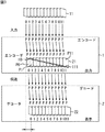
ローディレイコーディングでは、例えば、図3に示されるように、エンコーダ1は、ナンバ0乃至11のフレーム画像11を全てPピクチャとし、例えば、横45マクロブロック、縦24マクロブロの画枠サイズの中で、ナンバ0のフレーム画像の上段から縦2マクロブロック、および横45マクロブロック分の領域を、イントラスライスI0、その他の領域を全てインタースライスP0として設定する。
【0016】
そして、エンコーダ1は、次のナンバ1のフレーム画像においては、ナンバ0のフレーム画像のイントラスライスI0の下方向に続く位置に、同じ面積の領域でイントラスライスI1を設定し、その他は全てインタースライスP1に設定する。以下、同様にイントラスライスとインタースライスがフレーム画像ごとに設定され、最後のナンバ11のフレーム画像についてもイントラスライスI11とインタースライスP11が設定される。
【0017】
エンコーダ1は、各フレーム画像のイントラスライスI0乃至I11を、そのまま伝送データとして符号化し、他のインタースライスP0乃至P11を、前のフレーム画像の同じ領域の参照画像との差分データに基づいて符号化する(ただし、符号化の開始時においては、インタースライスP0の参照画像となる前のフレーム画像は存在しないので、符号化の開始時のみはこの限りでない)。そして、同様の符号化処理を、ナンバ0のフレーム画像からナンバ11のフレーム画像について繰り返し実行することにより、エンコーダ1は、1枚のPピクチャにおける画面全体の画像データを符号化して符号化フレーム21を生成することができる。
【0018】
この場合、各フレーム画像におけるイントラスライスI0乃至I11の画像データサイズは全て均一であり、当然、インタースライスP0乃至P11の画像データサイズも均一であることにより、フレーム画像毎の発生符号量は、ほぼ一定の固定レートになる。
【0019】
これにより、図4に示すように、Pピクチャの各フレーム画像は全て同じ発生符号量の符号化データとなり、VBVバッファに格納されるとき、および、引き抜かれるときの、VBVバッファにおける符号化データの推移は、全て同じになる。この結果、送信側のエンコーダ1は、デコーダ2のVBVバッファにアンダーフローおよびオーバーフローを生じさせることなく、符号化データの発生符号量を容易に制御することができ、発生符号量の多いIピクチャで生じるような遅延やリオーダリングディレイによる不具合を解消することができ、再生画像を遅延なく表示することができる。
【0020】
ところで、以上説明した構成の圧縮符号化装置においては、イントラスライスI0乃至I11に関してはそのまま伝送データとして符号化し、インタースライスP0乃至P11に関しては、前のフレーム画像における同じ領域の参照画像との差分データに基づいて符号化するため、イントラスライスI0乃至I11の画像データ部分を圧縮符号化したときの実際の発生符号量は多く、インタースライスP0乃至P11の画像データ部分を圧縮符号化したときの実際の発生符号量は少なくなる。
【0021】
ところが、ピクチャ全体としての発生符号量は規定されているが、イントラスライスI0乃至I11およびインタースライスP0乃至P11毎に割り当てる発生符号量は規定されていない。すなわち、イントラスライスI0乃至I11のように符号化したときの発生符号量が多くなる画像部分に対しても、またインタースライスP0乃至P11のように符号化したときの発生符号量があまり多くならない画像データ部分に対しても、均等に発生符号量が割り当てられている。
【0022】
従って、データ量の多いイントラスライスI0乃至I11に対して割り当てられる発生符号量が少なく、データ量の少ないインタースライスP0乃至P11に対して割り当てられる発生符号量が多くなることがあり、このような場合にピクチャ全体としての画像に歪みが生じてしまうという課題があった。
【0023】
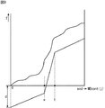
具体的には、図5に示されるように、画像の符号化難易度が低い画像31に続いて、画像の符号化難易度が高い画像32が存在した場合、符号化難易度が低い画像31は、エンコードに容易な画像であるため、Qスケールが小さくなるが、従来の方法では、それに続く、画像の符号化難易度が高い画像32に対して、小さなQスケールでエンコードを開始してしまうため、画面の途中までに、与えられたビット量を消費してしまい、画面下端に前のピクチャが残ってしまうという現象が発生する。この現象は、イントラスライスが、次に、画面下端の問題発生箇所に現れるまで、影響を及ぼしてしまう。
【0024】
この課題を解決するために、本出願人は、特開平11−205803において、ローディレイモードにおいても、復号器側において高画質な画像を再生できるような符号化データを生成し得る符号化装置および符号化方法を提案している。
【0025】
すなわち、通常のフィードバック型の量子化制御を行ってイントラスライスおよびインタースライスごとに最適な量子化ステップサイズを決定して量子化制御を行う場合において、次のピクチャが1つ前のピクチャと絵柄の大きく異なるシーンチェンジが起きた場合、1つ前のピクチャを基に算出された量子化インデックスデータQ(j+1)を用いるのではなく、これから符号化しようとするピクチャのME残差情報に基づいて、仮想バッファの初期バッファ容量d(0)を更新することにより、新たに量子化インデックスデータQ(j+1)が算出し直されるようにする。これにより、シーンチェンジが起きた場合でも、イントラスライスおよびインタースライスごとに最適な量子化ステップサイズが決定されて、量子化制御が行われる。
【0026】
ME残差とは、ピクチャ単位で算出されるものであり、1つ前のピクチャと次のピクチャにおける輝度の差分値の合計値である。従ってME残差情報が大きな値を示すときには、1つ前のピクチャの絵柄と次に符号化処理するピクチャの絵柄が大きく異なっていること(いわゆるシーンチェンジ)を表している。
【0027】
この符号化方法について、図6のフローチャートを参照して説明する。
【0028】
ステップS1において、例えば、動きベクトルを検出するときに得られるME残差情報が取得される。ここで取得されたME残差情報をME_infoとする。
【0029】
ステップS2において、取得されたME残差情報から、ME残差情報の平均値avgが減算されて、算出された値が、所定の閾値Dよりも大きいか否かが判断される。ME残差情報の平均値avgは、後述するステップS4において更新される値であり、次の式(1)で示される。
【0030】
avg=1/2(avg+ME_info)・・・(1)
【0031】
ステップS2において、算出された値は、所定の閾値Dより小さいと判断された場合、現在のピクチャにおける絵柄と、1つ前のピクチャにおける絵柄との差があまり無い、すなわちシーンチェンジがなかったと判断されるので、処理はステップS4に進む。
【0032】
ステップS2において、算出された値は、所定の閾値Dより大きいと判断された場合、現在のピクチャにおける絵柄と、1つ前のピクチャにおける絵柄との差が大きい、すなわち、シーンチェンジがあったと判断されるので、ステップS3において、式(2)、式(3)、式(4)および式(5)に基づいて、仮想バッファの初期バッファ容量d(0)が算出されて、仮想バッファが更新される。
【0033】
ピクチャ単位の画像の難しさGC(Global Complexity)を表すXは、次の式(2)で表される。
X=T×Q・・・(2)
ただし、Tは、ピクチャ単位の発生符号量であり、Qは、ピクチャ単位の量子化ステップサイズの平均値である。
【0034】
そして、ピクチャ単位の画像の難しさXを、ME残差情報ME_infoと等しいとした場合、すなわち、次の式(3)が満たされている場合、ピクチャ全体の量子化インデックスデータQは、式(4)で示される。
【0035】
X=ME_info・・・(3)
Q={d(0)×31}/{2×(br/pr)}・・・(4)
ただし、brは、ビットレートであり、prは、ピクチャレートである。
【0036】
そして、式(4)における仮想バッファの初期バッファ容量d(0)は、次の式(5)で示される。
d(0)=2×{(ME_info×br/pr)/31×T}・・・(5)
【0037】
この仮想バッファの初期バッファ容量d(0)を、再度、式(4)に代入することにより、ピクチャ全体の量子化インデックスデータQが算出される。
【0038】
ステップS2において、算出された値は、所定の閾値Dより小さいと判断された場合、もしくは、ステップS3の処理の終了後、ステップS4において、次に供給されるピクチャに備えて、ME残差情報の平均値avgが、上述した式(1)により計算されて更新され、処理は、ステップS1に戻り、それ以降の処理が繰り返される。
【0039】
図6のフローチャートを用いて説明した処理により、次のピクチャが1つ前のピクチャと絵柄の大きく異なるシーンチェンジが起きた場合には、これから符号化しようとするピクチャのME残差情報ME_infoに基づいて、仮想バッファの初期バッファ容量d(0)が更新され、この値を基に、新たに量子化インデックスデータQ(j+1)が算出されるので、シーンチェンジに対応して、イントラスライスおよびインタースライスごとに最適な量子化ステップサイズが決定される。
【0040】
【発明が解決しようとする課題】
しかしながら、特開平11−205803に記載の方法を用いた場合、符号化難易度が高い(難しい)画像から、符号化難易度が低い(易しい)画像にシーンが変わる場合などにおいても、同様のエンコード処理をしてしまうため、画質に悪影響を及ぼしてしまう。
【0041】
具体的には、易しい画像から難しい画像へシーンが変わる場合、および、難しい画像から易しい画像へシーンが変わる場合の双方に対して仮想バッファ調整を行ってしまうため、難しい画像から易しい画像へシーンが変わる場合では、エンコードに余裕があるはずの、符号化難易度が低い画像において、わざわざ画質を悪くしてしまう場合がある。
【0042】
また、シーンチェンジの影響で、イントラマクロブロックが多数発生してしまった場合、従来の仮想バッファの更新によるエンコード処理では、画像難易度が非常に高い画像をエンコードするとき、量子化スケールが最大値で張り付いた状態となり、画面上部で発生符号量を抑えることができなくなってしまうので、図5を用いて説明した画像32と同様に、画面下部の符号化に割り当てる符号量が足りなくなってしまう現象が発生する。
【0043】
これは、量子化をつかさどる量子化インデックスが略最大値で張り付いてしまうためである。
【0044】
本発明はこのような状況に鑑みてなされたものであり、様々なシーンチェンジに対応して、イントラスライスエンコードにおいて、シーンチェンジ時の画質を向上させることができるようにするものである。
【0045】
【課題を解決するための手段】
本発明の第1の符号化装置は、1つ前のピクチャである第1のピクチャと次に符号化処理するピクチャである第2のピクチャとの、絵柄の変化を検出する第1の検出手段と、第1の検出手段による検出結果を基に、第1のピクチャから第2のピクチャの間でシーンチェンジが発生したか否かを判断する判断手段と、仮想バッファの初期バッファ容量の値を用いて、量子化インデックスデータを決定する決定手段と、判断手段によりシーンチェンジが発生したと判断された場合、フレーム画像のビットレートが高いときよりも低いときのほうが、高周波成分を落とす値となるように、Qマトリクスを設定する設定手段と、決定手段により決定された量子化インデックスデータ、および設定手段により設定されたQマトリクスを基に、量子化を実行する量子化手段と、量子化手段により量子化された量子化係数データを符号化する符号化手段とを備えることを特徴とする。
【0047】
設定手段には、ビットレートが所定の閾値よりも小さい場合、高周波成分を落とす値となるように、Qマトリクスを設定させるようにすることができる。
【0048】
設定手段には、複数の閾値とビットレートとを比較させ、その比較結果に基づいて、ビットレートが低いほど高周波成分を落とす値となるように、Qマトリクスを設定させるようにすることができる。
【0049】
第1の検出手段には、第1のピクチャの絵柄と第2のピクチャの絵柄との差分を示す指標を算出させ、指標を基に、絵柄の変化を検出させるようにすることができる。
【0050】
第2のピクチャの画像難易度を検出する第2の検出手段を更に備えさせるようにすることができ、設定手段には、判断手段によりシーンチェンジが発生したと判断された場合、ビットレートが低いほど高周波成分を落とす値となるように、Qマトリクスを設定させることができるとともに、ビットレートが所定の閾値よりも低い値であるとき、第2の検出手段により検出された第2のピクチャの画像難易度が低いときよりも高いときのほうが高周波成分を落とす値となるように、Qマトリクスを設定させるようにすることができる。
【0051】
第2の検出手段には、フレーム画像の絵柄の難しさおよび圧縮後のデータ量と相関性を有する統計量であるフレーム画像の複雑さを、画像難易度を示す指標として算出させ、指標を基に、第2のピクチャの画像難易度を検出させるようにすることができる。
【0053】
設定手段には、画像難易度が所定の閾値よりも高い場合、画像難易度が所定の閾値よりも低いときよりも高周波成分を落とす値となるようにQマトリクスを設定させるようにすることができる。
【0054】
設定手段には、ビットレートが第1の閾値よりも小さく、かつ、画像難易度が第2の閾値よりも大きい場合、高周波成分を最も落とす第1のQマトリクスとなるようにQマトリクスを設定させることができ、ビットレートが第1の閾値よりも小さく、かつ、画像難易度が第2の閾値よりも小さい場合、第1のQマトリクスより細かく量子化を行う第2のQマトリクスとなるように、Qマトリクスを設定させることができ、ビットレートが第1の閾値と、第1の閾値よりも大きな第3の閾値との間の値であり、かつ、画像難易度が第2の閾値よりも大きな第4の閾値よりも大きい場合、第2のQマトリクスより細かく量子化を行う第3のQマトリクスとなるように、Qマトリクスを設定させることができ、ビットレートが第1の閾値と第3の閾値との間の値であり、かつ、画像難易度が第4の閾値よりも小さい場合、第3のQマトリクスより細かく量子化を行う第4のQマトリクスとなるように、Qマトリクスを設定させるようにすることができる。
【0055】
フレーム画像は、全て、フレーム間順方向予測符号化画像であるものとすることができる。
【0056】
本発明の第1の符号化方法は、1つ前のピクチャである第1のピクチャと次に符号化処理するピクチャである第2のピクチャとの、絵柄の変化を検出する検出ステップと、検出ステップの処理による検出結果を基に、第1のピクチャから第2のピクチャの間でシーンチェンジが発生したか否かを判断する判断ステップと、仮想バッファの初期バッファ容量の値を用いて、量子化インデックスデータを決定する決定ステップと、判断ステップの処理によりシーンチェンジが発生したと判断された場合、フレーム画像のビットレートが高いときよりも低いときのほうが、高周波成分を落とす値となるように、Qマトリクスを設定する設定ステップと、決定ステップの処理により決定された量子化インデックスデータ、および設定ステップの処理により設定されたQマトリクスを基に、量子化を実行する量子化ステップと、量子化ステップの処理により量子化された量子化係数データを符号化する符号化ステップとを含むことを特徴とする。
【0057】
本発明の第1の記録媒体に記録されているプログラムは、1つ前のピクチャである第1のピクチャと次に符号化処理するピクチャである第2のピクチャとの、絵柄の変化を検出する検出ステップと、検出ステップの処理による検出結果を基に、第1のピクチャから第2のピクチャの間でシーンチェンジが発生したか否かを判断する判断ステップと、仮想バッファの初期バッファ容量の値を用いて、量子化インデックスデータを決定する決定ステップと、判断ステップの処理によりシーンチェンジが発生したと判断された場合、フレーム画像のビットレートが高いときよりも低いときのほうが、高周波成分を落とす値となるように、Qマトリクスを設定する設定ステップと、決定ステップの処理により決定された量子化インデックスデータ、および設定ステップの処理により設定されたQマトリクスを基に、量子化を実行する量子化ステップと、量子化ステップの処理により量子化された量子化係数データを符号化する符号化ステップとを含むことを特徴とする処理をコンピュータに実行させる。
【0058】
本発明の第1のプログラムは、1つ前のピクチャである第1のピクチャと次に符号化処理するピクチャである第2のピクチャとの、絵柄の変化を検出する検出ステップと、検出ステップの処理による検出結果を基に、第1のピクチャから第2のピクチャの間でシーンチェンジが発生したか否かを判断する判断ステップと、仮想バッファの初期バッファ容量の値を用いて、量子化インデックスデータを決定する決定ステップと、判断ステップの処理によりシーンチェンジが発生したと判断された場合、フレーム画像のビットレートが高いときよりも低いときのほうが、高周波成分を落とす値となるように、Qマトリクスを設定する設定ステップと、決定ステップの処理により決定された量子化インデックスデータ、および設定ステップの処理により設定されたQマトリクスを基に、量子化を実行する量子化ステップと、量子化ステップの処理により量子化された量子化係数データを符号化する符号化ステップとを含むことを特徴とする処理をコンピュータに実行させる。
【0059】
本発明の第2の符号化装置は、次に符号化処理するピクチャである第1のピクチャの画像難易度を検出する第1の検出手段と、1つ前のピクチャである第2のピクチャと、第1のピクチャとの、絵柄の変化を検出する第2の検出手段と、第2の検出手段による検出結果を基に、第2のピクチャから第1のピクチャの間でシーンチェンジが発生したか否かを判断する判断手段と、仮想バッファの初期バッファ容量の値を用いて、量子化インデックスデータを決定する決定手段と、判断手段によりシーンチェンジが発生したと判断された場合、第1の検出手段により検出された画像難易度が低いときよりも高いときのほうが、高周波成分を落とす値となるように、Qマトリクスを設定する設定手段と、決定手段により決定された量子化インデックスデータ、および設定手段により設定されたQマトリクスを基に、量子化を実行する量子化手段と、量子化手段により量子化された量子化係数データを符号化する符号化手段とを備えることを特徴とする。
【0061】
設定手段には、画像難易度が所定の閾値よりも高い場合、高周波成分を落とす値となるようにQマトリクスを設定させるようにすることができる。
【0062】
設定手段には、複数の所定の閾値と画像難易度とを比較させ、その比較結果に基づいて、画像難易度が高いほど高周波成分を落とす値となるようにQマトリクスを設定させるようにすることができる。
【0063】
第2の検出手段には、第1のピクチャの絵柄と第2のピクチャの絵柄との差分を示す指標を算出させ、指標を基に、絵柄の変化を検出させるようにすることができる。
【0064】
第1の検出手段には、フレーム画像の絵柄の難しさおよび圧縮後のデータ量と相関性を有する統計量であるフレーム画像の複雑さを、画像難易度を示す指標として算出させ、指標を基に、第1のピクチャの画像難易度を検出させるようにすることができる。
【0065】
フレーム画像は、全て、フレーム間順方向予測符号化画像であるものとすることができる。
【0066】
本発明の第2の符号化方法は、次に符号化処理するピクチャである第1のピクチャの画像難易度を検出する第1の検出ステップと、1つ前のピクチャである第2のピクチャと、第1のピクチャとの、絵柄の変化を検出する第2の検出ステップと、第2の検出ステップの処理による検出結果を基に、第2のピクチャから第1のピクチャの間でシーンチェンジが発生したか否かを判断する判断ステップと、仮想バッファの初期バッファ容量の値を用いて、量子化インデックスデータを決定する決定ステップと、判断ステップの処理によりシーンチェンジが発生したと判断された場合、第1の検出ステップの処理により検出された画像難易度が低いときよりも高いときのほうが、高周波成分を落とす値となるように、Qマトリクスを設定する設定ステップと、決定ステップの処理により決定された量子化インデックスデータ、および設定ステップの処理により設定されたQマトリクスを基に、量子化を実行する量子化ステップと、量子化ステップの処理により量子化された量子化係数データを符号化する符号化ステップとを含むことを特徴とする。
【0067】
本発明の第2の記録媒体に記録されているプログラムは、次に符号化処理するピクチャである第1のピクチャの画像難易度を検出する第1の検出ステップと、1つ前のピクチャである第2のピクチャと、第1のピクチャとの、絵柄の変化を検出する第2の検出ステップと、第2の検出ステップの処理による検出結果を基に、第2のピクチャから第1のピクチャの間でシーンチェンジが発生したか否かを判断する判断ステップと、仮想バッファの初期バッファ容量の値を用いて、量子化インデックスデータを決定する決定ステップと、判断ステップの処理によりシーンチェンジが発生したと判断された場合、第1の検出ステップの処理により検出された画像難易度が低いときよりも高いときのほうが、高周波成分を落とす値となるように、Qマトリクスを設定する設定ステップと、決定ステップの処理により決定された量子化インデックスデータ、および設定ステップの処理により設定されたQマトリクスを基に、量子化を実行する量子化ステップと、量子化ステップの処理により量子化された量子化係数データを符号化する符号化ステップとを含むことを特徴とする処理をコンピュータに実行させる。
【0068】
本発明の第2のプログラムは、次に符号化処理するピクチャである第1のピクチャの画像難易度を検出する第1の検出ステップと、1つ前のピクチャである第2のピクチャと、第1のピクチャとの、絵柄の変化を検出する第2の検出ステップと、第2の検出ステップの処理による検出結果を基に、第2のピクチャから第1のピクチャの間でシーンチェンジが発生したか否かを判断する判断ステップと、仮想バッファの初期バッファ容量の値を用いて、量子化インデックスデータを決定する決定ステップと、判断ステップの処理によりシーンチェンジが発生したと判断された場合、第1の検出ステップの処理により検出された画像難易度が低いときよりも高いときのほうが、高周波成分を落とす値となるように、Qマトリクスを設定する設定ステップと、決定ステップの処理により決定された量子化インデックスデータ、および設定ステップの処理により設定されたQマトリクスを基に、量子化を実行する量子化ステップと、量子化ステップの処理により量子化された量子化係数データを符号化する符号化ステップとを含むことを特徴とする処理をコンピュータに実行させる。
【0069】
本発明の第1の符号化装置および符号化方法、並びにプログラムにおいては、1つ前のピクチャである第1のピクチャと次に符号化処理するピクチャである第2のピクチャとの絵柄の変化が検出され、第1のピクチャから第2のピクチャの間でシーンチェンジが発生したか否かが判断され、仮想バッファの初期バッファ容量の値を用いて、量子化インデックスデータが決定され、シーンチェンジが発生したと判断された場合、ビットレートが高いときよりも低いときのほうが、高周波成分を落とす値となるように、Qマトリクスが設定され、量子化インデックスデータ、およびQマトリクスを基に、量子化が実行され、量子化された量子化係数データが符号化される。
【0070】
本発明の第2の符号化装置および符号化方法、並びにプログラムにおいては、次に符号化処理するピクチャである第1のピクチャの難易度が検出され、1つ前のピクチャである第2のピクチャと、第1のピクチャとの、絵柄の変化が検出され、第2のピクチャから第1のピクチャの間でシーンチェンジが発生したか否かが判断され、仮想バッファの初期バッファ容量の値を用いて、量子化インデックスデータが決定され、シーンチェンジが発生したと判断された場合、画像難易度が低いときよりも高いときのほうが、高周波成分を落とす値となるように、Qマトリクスが設定され、量子化インデックスデータ、およびQマトリクスを基に、量子化が実行され、量子化された量子化係数データが符号化される。
【0071】
【発明の実施の形態】
以下、図を参照して、本発明の実施の形態について説明する。
【0072】
図7は、ビデオエンコーダ61の構成を示すブロック図である。
【0073】
ビデオエンコーダ61は、全てPピクチャを用いたローディレイコーディング方式によって、画像データを符号化するようになされている。ビデオエンコーダ61の前処理部71は、外部から供給される画像データの入力を受ける。
【0074】
前処理部71は、順次入力される画像データの各フレーム画像(この場合全てPピクチャ)を、16画素×16ラインの輝度信号、および輝度信号に対応する色差信号によって構成されるマクロブロックに分割し、これをマクロブロックデータとして、演算部72、動きベクトル検出部73、および、量子化制御部83のイントラAC算出部91に供給する。
【0075】
動きベクトル検出部73は、マクロブロックデータの入力を受け、各マクロブロックの動きベクトルを、マクロブロックデータ、および、フレームメモリ84に記憶されている参照画像データを基に算出し、動きベクトルデータとして、動き補償部81に送出する。
【0076】
演算部72は、前処理部71から供給されたマクロブロックデータについて、各マクロブロックの画像タイプに基づいて、イントラスライスI0乃至I11に対してはイントラモードで、インタースライスP0乃至P11に対しては順方向予測モードで、動き補償を行う。
【0077】
ここでイントラモードとは、符号化対象となるフレーム画像をそのまま伝送データとする方法であり、順方向予測モードとは、符号化対象となるフレーム画像と過去参照画像との予測残差を伝送データとする方法である。ビデオエンコーダ61においては、Pピクチャのみを使用して、イントラスライスI0乃至I11とインタースライスP0乃至P11に分けて符号化するようになされている。
【0078】
まず、マクロブロックデータが、イントラスライスI0乃至I11のうちの1つであった場合、マクロブロックデータはイントラモードで処理される。すなわち、演算部72は、入力されたマクロブロックデータのマクロブロックを、そのまま演算データとしてDCT(Discrete Cosine Transform :離散コサイン変換)部74に送出する。DCT部74は、入力された演算データに対しDCT変換処理を行うことによりDCT係数化し、これをDCT係数データとして、量子化部75に送出する。
【0079】
量子化部75は、発生符号量制御部92から供給される量子化インデックスデータQ(j+1)に、Qマトリクスの係数を乗算することにより、入力されたDCT係数データに対して量子化処理を行い、量子化DCT係数データとしてVLC(Variable Length Code;可変長符号化)部77および逆量子化部78に送出する。ここで、量子化部75は、発生符号量制御部92から供給される量子化インデックスデータQ(j+1)に応じて、量子化処理における量子化ステップサイズを調整することにより、発生する符号量を制御するようになされている。
【0080】
また、量子化インデックスデータQ(j+1)に乗算するQマトリクスの値は、シーンチェンジがあった場合には、発生符号量制御部92が実行する、図11乃至図14のフローチャートを用いて後述する、Qマトリクス設定処理1乃至Qマトリクス設定処理4のうちのいずれかの処理により、必要に応じて制御される値である。
【0081】
逆量子化部78に送出された量子化DCT係数データは、量子化部75と同じ量子化ステップサイズによる逆量子化処理を受け、DCT係数データとして、逆DCT部79に送出される。逆DCT部79は、供給されたDCT係数データに逆DCT処理を施し、生成された演算データは、演算部80に送出され、参照画像データとしてフレームメモリ84に記憶される。
【0082】
そして、マクロブロックデータがインタースライスP0乃至P11のうちの1つであった場合、演算部72はマクロブロックデータについて、順方向予測モードによる動き補償処理を行う。
【0083】
動き補償部81は、フレームメモリ84に記憶されている参照画像データを、動きベクトルデータに応じて動き補償し、順方向予測画像データを算出する。演算部72は、マクロブロックデータについて、動き補償部81より供給される順方向予測画像データを用いて減算処理を実行する。
【0084】
すなわち、動き補償部81は、順方向予測モードにおいて、フレームメモリ84の読み出しアドレスを、動きベクトルデータに応じてずらすことによって、参照画像データを読み出し、これを順方向予測画像データとして演算部72および演算部80に供給する。演算部72は、供給されたマクロブロックデータから、順方向予測画像データを減算して、予測残差としての差分データを得る。そして、演算部72は、差分データをDCT部74に送出する。
【0085】
また、演算部80には、動き補償部81より順方向予測画像データが供給されており、演算部80は、逆DCT部から供給された演算データに、順方向予測画像データを加算することにより、参照画像データを局部再生し、フレームメモリ84に出力して記憶させる。
【0086】
かくして、ビデオエンコーダ61に入力された画像データは、動き補償予測処理、DCT処理および量子化処理を受け、量子化DCT係数データとして、VLC部77に供給される。VLC部77は、量子化DCT係数データに対し、所定の変換テーブルに基づく可変長符号化処理を行い、その結果得られる可変長符号化データをバッファ82に送出するとともに、マクロブロックごとの符号化発生ビット数を表す発生符号量データB(j)を、量子化制御部83の発生符号量制御部92、およびGC(Global Complexity)算出部93にそれぞれ送出する。
【0087】
GC算出部93は、発生符号量データB(j)を、マクロブロックごとに順次蓄積し、1ピクチャ分の発生符号量データB(j)が全て蓄積された時点で、全マクロブロック分の発生符号量データB(j)を累積加算することにより、1ピクチャ分の発生符号量を算出する。
【0088】
そしてGC算出部93は、次の式(6)を用いて、1ピクチャのうちの、イントラスライス部分の発生符号量と、イントラスライス部分における量子化ステップサイズの平均値との積を算出することにより、イントラスライス部分の画像の難しさ(以下、これをGCと称する)を表すGCデータXiを求め、これを目標符号量算出部94に供給する。
【0089】
Xi=(Ti/Ni)×Qi・・・(6)
ここで、Tiは、イントラスライスの発生符号量、Niは、イントラスライス数、そして、Qiは、イントラスライスの量子化ステップサイズの平均値である。
【0090】
GC算出部93は、これと同時に、次に示す式(7)を用いて、1ピクチャのうちの、インタースライス部分の発生符号量と、このインタースライス部分における量子化ステップサイズの平均値との積を算出することにより、インタースライス部分におけるGCデータXpを求め、これを目標符号量算出部94に供給する。
【0091】
Xp=(Tp/Np)×Qp・・・(7)
ここで、Tpは、インタースライスの発生符号量、Npは、インタースライス数、Qpは、インタースライスの量子化ステップサイズの平均値である。
【0092】
目標符号量算出部94は、GC算出部93から供給されるGCデータXiを基に、次の式(8)を用いて、次のピクチャにおけるイントラスライス部分の目標発生符号量データTpiを算出するとともに、GC算出部93から供給されるGCデータXpを基に、次の式(9)を基に、次のピクチャにおけるインタースライス部分の目標発生符号量データTppを算出し、算出した目標発生符号量データTpiおよびTppを発生符号量制御部92にそれぞれ送出する。
【0093】
Tpi={(Ni×Xi)/(Np×Xp)+(Np×Xi)}×Xp・・・(8)
【0094】
Tpp={(Np×Xp)/(Np×Xp)+(Ni×Xi)}×Xp・・・(9)
【0095】
また、目標符号量算出部94は、操作入力部85を用いて、ユーザが入力したビットレートの値の入力を受け、符号量発生部92に供給する。
【0096】
ME残差算出部95は、入力されるマクロブロックデータを基に、ME残差情報ME_infoを算出して、発生符号量制御部92に出力する。ここで、ME残差情報ME_infoとは、ピクチャ単位で算出されるものであり、1つ前のピクチャと次のピクチャにおける輝度の差分値の合計値である。従って、ME残差情報ME_infoが大きな値を示すときには、1つ前のピクチャの絵柄と、次に符号化処理するピクチャの絵柄とが大きく異なっていること(いわゆるシーンチェンジ)を表している。
【0097】
1つ前のピクチャの絵柄と次に符号化処理するピクチャの絵柄が異なっている場合、1つ前のピクチャの画像データを用いて算出した目標発生符号量データTpiおよびTppを基に生成した量子化インデックスデータQ(j+1)によって、量子化部75の量子化ステップサイズを決定することは適切ではない。従って、シーンチェンジが起こった場合は、目標発生符号量データTpiおよびTppは、新たに算出されなおされるようにしても良い。
【0098】
イントラAC算出部91は、イントラAC(intra AC)を算出し、現在のイントラACの値を示すmad_infoと、一つ前のイントラACの値を示すprev_mad_infoとを、発生符号量制御部92に出力する。
【0099】
イントラACは、MPEG方式におけるDCT処理単位のDCTブロックごとの映像データとの分散値の総和として定義されるパラメータであって、映像の複雑さを指標し、映像の絵柄の難しさおよび圧縮後のデータ量と相関性を有する。すなわち、イントラACとは、DCTブロック単位で、それぞれの画素の画素値から、ブロック毎の画素値の平均値を引いたものの絶対値和の、画面内における総和である。イントラAC(IntraAC)は、次の式(10)で示される。
【0100】
【数1】

また、式(10)において、式(11)が成り立つ。
【数2】
画像の符号化難易度が易しいものから難しいものへのシーンチェンジ、および、難しいものから易しいものへのシーンチェンジの、双方に対して仮想バッファ調整を行ってしまった場合、難しいものから易しいものへのシーンチェンジでは、エンコードに余裕があるはずの易画像においてわざわざ画質を悪くしてしまう結果となる場合がある。また、難しいものから易しいものへのシーンチェンジであっても、その変化の大きさ、あるいは、シーンチェンジ後の画像の難易度によっては、仮想バッファの調整を行うほうがよい場合がある。しかしながら、ME残差情報のみでは、シーンチェンジの有無を判定することはできるが、シーンチェンジの内容が、易しいものから難しいものへのシーンチェンジであるか、あるいは、難しいものから易しいものへのシーンチェンジであるかを判定することができない。
【0103】
そこで、イントラAC算出部91が、イントラACを算出し、現在のイントラACの値を示すmad_infoと、一つ前のイントラACの値を示すprev_mad_infoとを、発生符号量制御部92に出力することにより、発生符号量制御部92は、シーンチェンジの状態を判定して、仮想バッファ調整を行うか否かを判断することができる。
【0104】
発生符号量制御部92は、バッファ82に格納される可変長符号化データの蓄積状態を常時監視しており、蓄積状態を表す占有量情報を基に量子化ステップサイズを決定するようになされている。
【0105】
また、発生符号量制御部92は、イントラスライス部分の目標発生符号量データTpiよりも実際に発生したマクロブロックの発生符号量データB(j)が多い場合、発生符号量を減らすために量子化ステップサイズを大きくし、また、目標発生符号量データTpiよりも実際の発生符号量データB(j)が少ない場合、発生符号量を増やすために量子化ステップサイズを小さくするようになされている。
【0106】
更に、発生符号量制御部92は、インタースライス部分の場合も同様に、目標発生符号量データTppよりも実際に発生したマクロブロックの発生符号量データB(j)が多い場合、発生符号量を減らすために量子化ステップサイズを大きくし、また、目標発生符号量データTppよりも実際の発生符号量データB(j)が少ない場合、発生符号量を増やすために量子化ステップサイズを小さくするようになされている。
【0107】
すなわち、発生符号量制御部92は、デコーダ側に設けられたVBVバッファに格納された可変長符号化データの蓄積状態の推移を想定することにより、図8に示されるように、j番目のマクロブロックにおける仮想バッファのバッファ占有量d(j)を次の式(12)によって表し、また、j+1番目のマクロブロックにおける仮想バッファのバッファ占有量d(j+1)を次の式(13)によって表し、(12)式から(13)式を減算することにより、j+1番目のマクロブロックにおける仮想バッファのバッファ占有量d(j+1)を次の式(14)として変形することができる。
【0108】
d(j)=d(0)+B(j−1)−{T×(j−1)/MBcnt}・・・(12)
【0109】
ここで、d(0)は初期バッファ容量、B(j)は、j番目のマクロブロックにおける符号化発生ビット数、MBcntは、ピクチャ内のマクロブロック数、そして、Tは、ピクチャ単位の目標発生符号量である。
【0110】
d(j+1)=d(0)+B(i)−(T×j)/MBcnt・・・(13)
【0111】
d(j+1)=d(j)+{B(j)−B(j−1)}−T/MBcnt・・・(14)
【0112】
続いて、発生符号量制御部92は、ピクチャ内のマクロブロックがイントラスライス部分とインタースライス部分とに分かれているため、図9に示されるように、イントラスライス部分のマクロブロックとインタースライス部分の各マクロブロックに割り当てる目標発生符号量TpiおよびTppをそれぞれ個別に設定する。
【0113】
グラフにおいて、マクロブロックのカウント数が0乃至s、および、t乃至endの間にあるとき、次の式(15)に、インタースライスの目標発生符号量Tppを代入することにより、インタースライス部分におけるバッファ占有量d(j+1)を得ることができる。
【0114】
また、マクロブロックのカウント数がs乃至tの間にあるときに、次の式(16)に、イントラスライスの目標発生符号量Tpiを代入することにより、イントラスライス部分におけるバッファ占有量d(j+1)を得ることができる。
【0116】
d(j+1)=d(j)+{B(j)−B(j−1)}−Tpi/(t−s)・・・(16)
【0117】
従って、発生符号量制御部92は、イントラスライス部分およびインタースライス部分におけるバッファ占有量d(j+1)、および、式(17)に示される定数rを、式(18)に代入することにより、マクロブロック(j+1)の量子化インデックスデータQ(j+1)を算出し、これを量子化部75に供給する。
【0118】
r=(2×br)/pr ・・・(17)
Q(j+1)=d(j+1)×(31/r) ・・・(18)
ここで、brは、ビットレートであり、prは、ピクチャレートである。
【0119】
更に、発生符号量制御部92は、シーンチェンジがあった場合、図11乃至図14のフローチャートを用いて後述する、Qマトリクス設定処理1乃至Qマトリクス設定処理4のうちのいずれかの処理により、必要に応じて、量子化部75が量子化に用いるQマトリクスの値を制御する。
【0120】
量子化部75は、量子化インデックスデータQ(j+1)、および、発生符号量制御部92の処理により制御される値であるQマトリクスに基づいて、次のマクロブロックにおけるイントラスライスまたはインタースライスに応じた量子化ステップサイズを決定し、量子化ステップサイズによってDCT係数データを量子化する。
【0121】
これにより、量子化部75は、1つ前のピクチャのイントラスライス部分およびインタースライス部分における実際の発生符号量データB(j)に基づいて算出された、次のピクチャのイントラスライス部分およびインタースライス部分における目標発生符号量TppおよびTpiにとって最適な量子化ステップサイズによって、DCT係数データを量子化することができる。
【0122】
かくして、量子化部75では、バッファ82のデータ占有量に応じて、バッファ82がオーバーフローまたはアンダーフローしないように量子化し得るとともに、デコーダ側のVBVバッファがオーバーフロー、またはアンダーフローしないように量子化した量子化DCT係数データを生成することができる。
【0123】
例えば、従来の技術として上述した、特願平11−205803では、通常のフィードバック型の量子化制御を行いながら、次に符号化処理するピクチャの絵柄が大きく変化する場合には、フィードバック型の量子化制御を止め、ME残差算出部95から供給されるME残差情報に基づいて、仮想バッファの初期バッファ容量d(0)を初期化し、新たな初期バッファ容量d(0)を基に、イントラスライスおよびインタースライスごとに量子化インデックスデータQ(j+1)を新たに算出するようになされている。
【0124】
しかしながら、従来における場合のように、ME残差のみで仮想バッファ調整を行うか否かを判定してしまうと、画像難易度が易しいものから難しいものに変わった場合、および難しいものから簡単なものに変わった場合の双方に対して、仮想バッファ調整を行ってしまう。すなわち、画像難易度が難しいものから簡単なものに変わった場合では、エンコードに余裕があるはずの簡単な画像において、わざわざ画質を悪くしてしまう結果となる。
【0125】
そこで、図7のビデオエンコーダ61においては、例えば、イントラAC算出部91によって算出されるイントラACなどの情報を用いて、画像難易度が易しいものから難しいものに変わるシーンチェンジの時にのみ、仮想バッファ調整を行うようにすることにより、簡単な画像での画質の劣化を防ぐようにすることができる。
【0126】
すなわち、発生符号量制御部92は、通常のフィードバック型の量子化制御を行いながら、次に符号化処理するピクチャの絵柄が大きく変化する場合には、フィードバック型の量子化制御を止め、ME残差算出部95から供給されるME残差情報ME_info、並びに、イントラAC算出部91から供給される、prev_mad_infoおよびmad_infoを基に、仮想バッファの初期バッファ容量d(0)を初期化するか否かを判断し、仮想バッファの初期バッファ容量d(0)を初期化する場合は、ME残差算出部95から供給されるME残差情報ME_infoに基づいて、仮想バッファの初期バッファ容量d(0)を初期化する。仮想バッファの初期バッファ容量d(0)の初期化については、式(2)乃至式(5)を用いて説明した従来における場合と同様である。
【0127】
そして、発生符号量制御部92は、新たな初期バッファ容量d(0)を基に、イントラスライスおよびインタースライスごとに、式(12)乃至式(18)を用いて、量子化インデックスデータQ(j+1)を新たに算出し、量子化部75に供給する。
【0128】
更に、発生符号量制御部92は、次に符号化処理するピクチャの絵柄が大きく変化する場合には、ビットレート、あるいは、画像難易度、もしくはビットレートおよび画像難易度を基に、量子化部75を制御して、Qマトリクスの値を設定する。具体的には、発生符号量制御部92は、符号化が困難な、低ビットレートや難易度の高い画像においては、粗く量子化を行うように、Qマトリクスの値を設定し、符号化がある程度容易な、高ビットレートや難易度の低い画像においては、レート制御に余裕があるにもかかわらず、画質を劣化させてしまうようなことがないように、Qマトリクスの値を設定する。
【0129】
図10のフローチャートを参照して、イントラACなどの画像難易度情報を用いて、シーンチェンジは、簡単な画像から難しい画像への変化であるか否かの判定を導入して仮想バッファの調整を行う、仮想バッファ更新処理について説明する。
【0130】
ステップS21において、発生符号量制御部92は、ME残差算出部95から、ME残差情報ME_info を取得する。
【0131】
ステップS22において、発生符号量制御部92は、取得されたME残差情報から、ME残差情報の平均値avgを減算し、ME_info−avg > Dであるか否か、すなわち、算出された値が、所定の閾値Dよりも大きいか否かが判断される。ME残差情報の平均値avgは、後述するステップS26において更新される値であり、上述した式(1)で示される。なお、所定の閾値Dは、画質を検討しながらチューニングされる性質の値である。
【0132】
ステップS22において、算出された値は、所定の閾値Dより小さいと判断された場合、現在のピクチャにおける絵柄と、1つ前のピクチャにおける絵柄との差があまり無い、すなわちシーンチェンジがなかったと判断されるので、処理はステップS26に進む。
【0133】
ステップS22において、算出された値は、所定の閾値Dより大きいと判断された場合、現在のピクチャにおける絵柄と、1つ前のピクチャにおける絵柄との差が大きい、すなわち、シーンチェンジがあったと判断されるので、ステップS23において、発生符号量制御部92は、図11乃至図14を用いて説明するQマトリクス設定処理1乃至4のうちのいずれかの処理を実行する。ここで、Qマトリクスの設定は、ビットレートやシーンチェンジ後の画像の難易度に基づいて設定される。
【0134】
ステップS24において、発生符号量制御部92は、イントラAC算出部91から取得される、このシーンチェンジの後のイントラACの値であるmad_infoと、このシーンチェンジの前のイントラACの値であるprev_mad_infoとを比較し、mad_info > prev_mad_infoであるか否かを判断する。
【0135】
ステップS24において、mad_info > prev_mad_infoではないと判断された場合、このシーンチェンジは、難しい画像から、簡単な画像へのシーンチェンジであるので、処理は、ステップS26に進む。
【0136】
ステップS24において、mad_info > prev_mad_infoであると判断された場合、このシーンチェンジは、簡単な画像から、難しい画像へのシーンチェンジであるので、ステップS25において、発生符号量制御部92は、図1を用いて説明した従来における場合と同様の処理により、仮想バッファの初期バッファ容量d(0)の更新を行う。
【0137】
すなわち、発生符号量制御部92は、上述した式(2)、式(3)、式(4)および式(5)に基づいて、仮想バッファの初期バッファ容量d(0)を算出し、仮想バッファを更新する。
【0138】
ステップS22において、算出された値は、所定の閾値Dより小さいと判断された場合、ステップS24において、mad_info > prev_mad_infoではないと判断された場合、もしくは、ステップS25の処理の終了後、ステップS26において、発生符号量制御部92は、次に供給されるピクチャに備えて、ME残差情報の平均値avgを、上述した式(1)により更新し、処理は、ステップS21に戻り、それ以降の処理が繰り返される。
【0139】
図10のフローチャートを用いて説明した処理により、イントラACを用いて、画像難易度が易しいものから難しいものに変更されるシーンチェンジの時にのみ仮想バッファ調整を行うようにしたので、エンコードに余裕があるはずの簡単な画像において、更に画質を悪くしてしまうことを防ぐことができる。
【0140】
また、シーンチェンジが発生した場合、図11乃至図14のフローチャートを用いて後述するQマトリクス設定処理1乃至Qマトリクス設定処理4のうちのいずれかの処理が実行されて、画像のビットレートや難易度に適したQマトリクスが設定される。
【0141】
次に、図11のフローチャートを参照して、図10のステップS23において実行される、Qマトリクス設定処理1について説明する。Qマトリクス設定処理1においては、ビットレートを基にQマトリクスを変更するか否かが判断される。
【0142】
ステップS41において、発生符号量制御部92は、目標符号量算出部94から供給されるビットレートの値は、所定の閾値Aより小さな値であるか否かを判断する。
【0143】
ステップS41において、ビットレートの値は、所定の閾値Aより小さな値であると判断された場合、ステップS42において、発生符号量制御部92は、Qマトリクスの値を、高周波成分を落とすことができる値に変更させるための制御信号を生成し、量子化部75に出力する。量子化部75は、発生符号量制御部92から供給された制御信号に基づいて、量子化処理を実行する場合のQマトリクスの値を、高周波成分を落とすことができる値に変更し、処理は、図10のステップS24に戻る。
【0144】
ステップS41において、ビットレートの値は、所定の閾値Aより小さな値ではないと判断された場合、ステップS43において、発生符号量制御部92は、Qマトリクスの値を変更させないので、制御信号を量子化部75に出力しない。従って、量子化部75は、量子化処理を実行するときに、通常のQマトリクスの値を用いることとなる。ステップS43の処理の終了後、処理は、図10のステップS24に戻る。
【0145】
すなわち、低いビットレートでは、符号化に余裕がなくなるため、Qマトリクスの値を、高周波成分を落とすことができる値に変更することにより、イントラスライスエンコードのシーンチェンジ時の画質を向上させることができるが、高いビットレートで同様の処理を行ってしまうと、符号化に余裕があるのにもかかわらず、粗く量子化することになってしまうため、画質を劣化してしまうことになってしまう。従って、ビットレートが所定の閾値よりも低い場合のみ、Qマトリクスを変更させるようにする。
【0146】
図11のフローチャートを用いて説明した処理により、シーンチェンジが発生した場合、ビットレートに基づいて、Qマトリクスを変更するか否かを決定するようにしたので、イントラスライスエンコードのシーンチェンジ時の画質を向上させることができる。
【0147】
ここでは、ただ1つの閾値を用いて、ビットレートの高低を判断するようにしているが、複数の閾値を用いて、ビットレートの高低を判断するようにしても良いことは言うまでもない。この場合、ビットレートが低いと判断されるほど、粗い量子化が実行されるようなQマトリクスが設定される。
【0148】
Qマトリクス設定処理1においては、ビットレートを基にQマトリクスを変更するか否かが判断されたが、シーンチェンジ後の画像難易度を基に、Qマトリクスの設定値を変更するようにしてもよい。図12のフローチャートを参照して、シーンチェンジ後の画像難易度を基に、Qマトリクスの設定値を変更するQマトリクス設定処理2について説明する。
【0149】
ステップS51において、発生符号量制御部92は、イントラAC算出部91から供給されたmad_infoの値と、所定の閾値Bを比較して、mad_info>閾値Bが成り立っているか否かを判断する。
【0150】
ステップS51において、mad_info>閾値Bが成り立っていると判断された場合、シーンチェンジ後の画像は、画像難易度が高いため符号化が困難な画像であるので、ステップS52において、発生符号量制御部92は、Qマトリクスの値を、高周波成分を落とすことができ、粗い量子化を実行する第1の値に変更させるための制御信号を生成し、量子化部75に出力する。量子化部75は、発生符号量制御部92から供給された制御信号に基づいて、量子化処理を実行する場合のQマトリクスの値を、高周波成分を落とすことができる第1の値に変更し、処理は、図10のステップS24に戻る。
【0151】
ステップS51において、mad_info>閾値Bが成り立っていないと判断された場合、シーンチェンジ後の画像は、画像難易度が低く、ある程度符号化が易しい画像であるので、ステップS53において、発生符号量制御部92は、Qマトリクスの値を、通常処理よりは高周波成分を落とすことができるが、第1の値と比較して細かく量子化することができる第2の値に変更させるための制御信号を生成し、量子化部75に出力する。量子化部75は、発生符号量制御部92から供給された制御信号に基づいて、Qマトリクスの値を、高周波成分を落とすことができる第2の値に変更し、処理は、図10のステップS24に戻る。
【0152】
図12のフローチャートを用いて説明した処理により、シーンチェンジが発生した場合、シーンチェンジ後の画像難易度に基づいて、Qマトリクスの値を設定するようにしたので、イントラスライスエンコードのシーンチェンジ時の画質を向上させることができる。
【0153】
なお、図12においては、mad_info>閾値Bが成り立っているか否かを基に、Qマトリクスの値を、第1の値にするか第2の値にするかを決定するようにしたが、例えば、mad_info>閾値Bが成り立っているか否かを基に、Qマトリクスの値を変更するか否かを決定するようにしても良い。
【0154】
ここでは、ただ1つの閾値を用いて、シーンチェンジ後の画像難易度の高低を判断するようにしているが、複数の閾値を用いて、画像難易度の高低を判断するようにしても良いことは言うまでもない。この場合、画像難易度が高いと判断されるほど、粗い量子化が実行されるようなQマトリクスが設定される。
【0155】
Qマトリクス設定処理1においては、ビットレートを基にQマトリクスを変更するか否かが判断され、Qマトリクス設定処理2においては、シーンチェンジ後の画像難易度を基に、Qマトリクスの設定値を変更するようになされていたが、ビットレートおよびシーンチェンジ後の画像難易度の両方の値に基づいて、Qマトリクスの設定値を設定するようにしてもよい。図13のフローチャートを参照して、シーンチェンジ後のビットレートおよび画像難易度を基に、Qマトリクスの設定値を変更するQマトリクス設定処理3について説明する。
【0156】
ステップS61において、発生符号量制御部92は、目標符号量算出部94から供給されるビットレートの値は、所定の閾値Aより小さな値であるか(すなわち、符号化に余裕のない低いビットレートであるか)否かを判断する。
【0157】
ステップS61において、ビットレートの値は、所定の閾値Aより小さな値であると判断された場合、ステップS62において、発生符号量制御部92は、イントラAC算出部91から供給されたmad_infoの値と、所定の閾値Bを比較して、mad_info>閾値Bが成り立っているか否かを判断する。
【0158】
ステップS62において、mad_info>閾値Bが成り立っていると判断された場合、シーンチェンジ後の画像は、画像難易度が高いため符号化が困難な画像であるので、ステップS63において、発生符号量制御部92は、Qマトリクスの値を、高周波成分を落とすことができ、粗い量子化を実行する第1の値に変更させるための制御信号を生成し、量子化部75に出力する。量子化部75は、発生符号量制御部92から供給された制御信号に基づいて、量子化処理を実行するときのQマトリクスの値を、高周波成分を落とすことができる第1の値に変更し、処理は、図10のステップS24に戻る。
【0159】
ステップS62において、mad_info>閾値Bが成り立っていないと判断された場合、シーンチェンジ後の画像は、画像難易度が低く、ある程度符号化が易しい画像であるので、ステップS64において、発生符号量制御部92は、Qマトリクスの値を、通常処理よりは高周波成分を落とすことができるが、第1の値と比較して細かく量子化することができる第2の値に変更させるための制御信号を生成し、量子化部75に出力する。量子化部75は、発生符号量制御部92から供給された制御信号に基づいて、量子化処理を実行するときのQマトリクスの値を、高周波成分を落とすことができる第2の値に変更し、処理は、図10のステップS24に戻る。
【0160】
ステップS61において、ビットレートの値は、所定の閾値Aより小さな値ではないと判断された場合、ステップS65において、発生符号量制御部92は、符号化に余裕があるのにもかかわらず、粗く量子化して、画像を劣化してしまうことを避けるため、Qマトリクスの値を変更させないので、制御信号を量子化部75に出力しない。従って、量子化部75は、通常のQマトリクスの値を用いて量子化処理を実行するようになされる。ステップS65の処理の終了後、処理は、図10のステップS24に戻る。
【0161】
図13のフローチャートを用いて説明した処理により、ビットレートおよびシーンチェンジ後の画像難易度の両方の値に基づいて、Qマトリクスの設定値が設定されるので、必要以上に画像を劣化させてしまうことなく、シーンチェンジ後の画像の下部において、符号化に割り当てる符号量が足りなくなってしまう現象の発生を抑制することが可能となる。
【0162】
また、ビットレートおよび画像難易度の閾値を、それぞれ複数設けることにより、更に詳細に場合分けを行い、必要以上に画像を劣化させてしまうことなく、シーンチェンジ後の画像の下部において、符号化に割り当てる符号量が足りなくなってしまう現象の発生を効果的に抑制するようにすることができる。次に、図14のフローチャートを参照して、ビットレートおよび画像難易度の閾値を複数設けるようにした、Qマトリクス設定処理4について説明する。
【0163】
ステップS71において、発生符号量制御部92は、目標符号量算出部94から供給されるビットレートの値は、所定の閾値Eより小さな値であるか否かを判断する。ここで、閾値Eは、符号化が困難である小さなビットレートにおいて、更に詳細に符号化の余裕度を判断するために、図10、または図13のフローチャートを用いて説明した処理における閾値Aより小さい値とするほうが好適である。
【0164】
ステップS71において、ビットレートの値は、所定の閾値Eより小さな値であると判断された場合、ステップS72において、発生符号量制御部92は、イントラAC算出部91から供給されたmad_infoの値と、所定の閾値Gを比較して、mad_info>閾値Gが成り立っているか否かを判断する。ここで、閾値Gは、符号化が困難である高ビットレートの画像において、比較的広い範囲で画像難易度の高い画像を選択することができる値に設定することが好ましく、基本的に、図11、または図13のフローチャートを用いて説明した処理における閾値Bと略同等、または、閾値Bよりも小さな値とすると好適である。
【0165】
ステップS72において、mad_info>閾値Gが成り立っていると判断された場合、シーンチェンジ後の画像は、画像難易度が非常に高いため符号化が困難な画像であるので、ステップS73において、発生符号量制御部92は、Qマトリクスの値を、高周波成分を落とすことができ、Qマトリクス設定処理4のうち、最も粗い量子化を実行する第3の値に変更させるための制御信号を生成し、量子化部75に出力する。量子化部75は、発生符号量制御部92から供給された制御信号に基づいて、量子化処理を実行するときのQマトリクスの値を、第3の値に変更し、処理は、図10のステップS24に戻る。
【0166】
ステップS72において、mad_info>閾値Gが成り立っていないと判断された場合、シーンチェンジ後の画像は、画像難易度が低く、ある程度符号化が易しい画像であるので、ステップS74において、発生符号量制御部92は、Qマトリクスの値を、高周波成分を落とすことができ、Qマトリクス設定処理4のうち、2番目に粗い量子化を実行する第4の値に変更させるための制御信号を生成し、量子化部75に出力する。量子化部75は、発生符号量制御部92から供給された制御信号に基づいて、量子化処理を実行するときのQマトリクスの値を、第4の値に変更し、処理は、図10のステップS24に戻る。
【0167】
ステップS71において、ビットレートの値は、所定の閾値Eより小さな値ではないと判断された場合、ステップS75において、発生符号量制御部92は、目標符号量算出部94から供給されるビットレートの値は、所定の閾値Fより小さな値であるか否かを判断する。ここで、符号化の余裕度を判断するための閾値である閾値Fは、閾値Eよりも大きな値であり、基本的に、図10、または図13のフローチャートを用いて説明した処理における閾値Aと略同等の値とすると好適である。
【0168】
ステップS75において、ビットレートの値は、所定の閾値Fより小さな値であると判断された場合、ステップS76において、発生符号量制御部92は、イントラAC算出部91から供給されたmad_infoの値と、所定の閾値Hを比較して、mad_info>閾値Hが成り立っているか否かを判断する。
【0169】
ここで、閾値Hは、閾値Gより大きな値である。すなわち、ビットレートが閾値Eよりも小さな、低ビットレートの画像においては、画面下部まで正しく符号化させるために、難易度の高い画像を充分広い範囲で選択して、選択された画像におけるQマトリクスの値を、粗い量子化を実行させる第3の値に設定させる必要がある。これに対して、ビットレートが、閾値Eよりは大きく、閾値Fより小さな画像においては、ビットレートが高い分だけ、レート制御に余裕が生じるので、ビットレートが閾値Eよりも小さな場合よりも高い難易度の画像のみ、画面下部で符号量が不足する。従って、閾値Hを閾値Gよりも大きな値にしなければ、レート制御に余裕がある画像において、必要以上に量子化を粗くして、画質を低下させてしまう。
【0170】
ステップS76において、mad_info>閾値Hが成り立っていると判断された場合、シーンチェンジ後の画像は、画像難易度が非常に高いため符号化が困難な画像であるので、ステップS77において、発生符号量制御部92は、Qマトリクスの値を、Qマトリクス設定処理4のうち、3番目に粗い量子化を実行する第5の値に変更させるための制御信号を生成し、量子化部75に出力する。量子化部75は、発生符号量制御部92から供給された制御信号に基づいて、量子化処理を実行するときのQマトリクスの値を、第5の値に変更し、処理は、図10のステップS24に戻る。
【0171】
ステップS76において、mad_info>閾値Hが成り立っていないと判断された場合、シーンチェンジ後の画像は、画像難易度が低く、ある程度符号化が易しい画像であるので、ステップS78において、発生符号量制御部92は、Qマトリクスの値を、変更なしの場合の量子化よりは粗い量子化を実行するが、Qマトリクス設定処理4によって変更されて設定されるうちでは、もっとも細かい量子化を実行する第6の値に変更させるための制御信号を生成し、量子化部75に出力する。量子化部75は、発生符号量制御部92から供給された制御信号に基づいて、量子化処理を実行するときのQマトリクスの値を、第6の値に変更し、処理は、図10のステップS24に戻る。
【0172】
ステップS75において、ビットレートの値は、所定の閾値Fより小さな値ではないと判断された場合、ステップS79において、発生符号量制御部92は、符号化に余裕があるのにもかかわらず、粗く量子化して、画像を劣化してしまうことを避けるため、Qマトリクスの値を変更させないので、制御信号を量子化部75に出力しない。従って、量子化部75は、量子化処理を実行するとき、通常のQマトリクスの値を用いる。ステップS79の終了後、処理は、図10のステップS24に戻る。
【0173】
図14のフローチャートを用いて説明した処理により、ビットレートおよび画像難易度の閾値を複数設けて、更に詳細に場合分けを行うようにすることで、必要以上に画像を劣化させてしまうことなく、シーンチェンジ後の画像の下部において、符号化に割り当てる符号量が足りなくなってしまう現象の発生を効果的に抑制するようにすることができる。
【0174】
なお、図14のフローチャートを用いて説明した処理においては、ビットレートおよび画像難易度の閾値をそれぞれ2つ設けた場合について説明したが、ビットレートおよび画像難易度の閾値を、それぞれ、2つ以上設けるようにしても良いことは言うまでもない。ビットレートおよび画像難易度の閾値を、画像符号化が困難な部分においてより細かく設定する(多くの閾値を設定する)ことにより、画像を劣化させることなく、シーンチェンジ後の画像の下部において、符号化に割り当てる符号量が足りなくなってしまう現象の発生を、更に効果的に抑制するようにすることができる。
【0175】
また、上述の実施の形態においては、ローディレイコーディングとしてナンバ0乃至11の各フレーム画像を全てPピクチャとし、例えば、横45マクロブロック、縦24マクロブロックの画枠サイズの中でフレーム画像の上段から縦2マクロブロックおよび横45マクロブロック分の領域を1つのイントラスライス部分、他を全てインタースライス部分として設定するようにした場合について述べたが、本発明はこれに限らず、例えば、イントラスライス部分を縦1マクロブロック、横45マクロブロック分の領域とするなど、他の種々の大きさの領域で形成するようにしても良い。
【0176】
また、ここでは、ローディレイエンコードを行う場合を例として説明したが、本発明は、例えば、15フレームを、フレーム内符号化画像(以下、Iピクチャと称する)、フレーム間順方向予測符号化画像(以下、Pピクチャと称する)、もしくは、双方向予測符号化画像(以下、Bピクチャと称する)の3つの画像タイプのうちのいずれの画像タイプとして処理するかを指定し、指定されたフレーム画像の画像タイプ(Iピクチャ、Pピクチャ、あるいは、Bピクチャ)に応じて、フレーム画像を符号化するような場合にも適用可能である。
【0177】
更に、上述の実施の形態においては、本発明をMPEG方式によって圧縮符号化する符号化装置としてのビデオエンコーダ61に適用するようにした場合について述べたが、本発明はこれに限らず、他の種々の画像圧縮方式による符号化装置に適用するようにしても良い。
【0178】
上述した一連の処理は、ハードウエアにより実行させることもできるが、ソフトウエアにより実行させることもできる。この場合、例えば、ビデオエンコーダ61は、図15に示されるようなパーソナルコンピュータ101により構成される。
【0179】
図15において、CPU111は、ROM112に記憶されているプログラム、または記憶部118からRAM113にロードされたプログラムに従って、各種の処理を実行する。RAM113にはまた、CPU111が各種の処理を実行する上において必要なデータなども適宜記憶される。
【0180】
CPU111、ROM112、およびRAM113は、バス114を介して相互に接続されている。このバス114にはまた、入出力インタフェース115も接続されている。
【0181】
入出力インタフェース115には、キーボード、マウスなどよりなる入力部116、ディスプレイやスピーカなどよりなる出力部117、ハードディスクなどより構成される記憶部118、モデム、ターミナルアダプタなどより構成される通信部119が接続されている。通信部119は、インターネットを含むネットワークを介しての通信処理を行う。
【0182】
入出力インタフェース115にはまた、必要に応じてドライブ120が接続され、磁気ディスク131、光ディスク132、光磁気ディスク133、あるいは、半導体メモリ134などが適宜装着され、それらから読み出されたコンピュータプログラムが、必要に応じて記憶部118にインストールされる。
【0183】
一連の処理をソフトウエアにより実行させる場合には、そのソフトウエアを構成するプログラムが、専用のハードウエアに組み込まれているコンピュータ、または、各種のプログラムをインストールすることで、各種の機能を実行することが可能な、例えば汎用のパーソナルコンピュータなどに、ネットワークや記録媒体からインストールされる。
【0184】
この記録媒体は、図15に示されるように、装置本体とは別に、ユーザにプログラムを供給するために配布される、プログラムが記憶されている磁気ディスク131(フロッピディスクを含む)、光ディスク132(CD-ROM(Compact Disk-Read Only Memory),DVD(Digital Versatile Disk)を含む)、光磁気ディスク133(MD(Mini-Disk)(商標)を含む)、もしくは半導体メモリ134などよりなるパッケージメディアにより構成されるだけでなく、装置本体に予め組み込まれた状態でユーザに供給される、プログラムが記憶されているROM112や、記憶部118に含まれるハードディスクなどで構成される。
【0185】
なお、本明細書において、記録媒体に記憶されるプログラムを記述するステップは、含む順序に沿って時系列的に行われる処理はもちろん、必ずしも時系列的に処理されなくとも、並列的あるいは個別に実行される処理をも含むものである。
【0186】
【発明の効果】
本発明によれば、画像データをエンコードすることができる。
また、本発明によれば、量子化に用いられる係数(Qマトリクス)の設定を、シーンチェンジが発生したと判断された場合、ビットレートが高いときよりも低いときのほうが、高周波成分を落とす値となるように変更するようにしたので、シーンチェンジ時に必要以上に画像を劣化させることなく、シーンチェンジ後の画像の下部において、符号化に割り当てる符号量が足りなくなってしまう現象の発生を、効果的に抑制するようにすることができる。
また、他の本発明によれば、画像データをエンコードすることができる他に、量子化に用いられる係数(Qマトリクス)の設定を、シーンチェンジが発生したと判断された場合、画像難易度が低いときよりも高いときのほうが、高周波成分を落とす値となるように変更するようにしたので、シーンチェンジ時に必要以上に画像を劣化させることなく、シーンチェンジ後の画像の下部において、符号化に割り当てる符号量が足りなくなってしまう現象の発生を、効果的に抑制するようにすることができる。
【図面の簡単な説明】
【図1】MPEG2方式によって映像データを圧縮符号化する場合、および圧縮符号化された画像データを復号する場合の処理について説明する図である。
【図2】VBVバッファについて説明する図である。
【図3】ローディレイコーディングについて説明する図である。
【図4】VBVバッファについて説明する図である。
【図5】シーンチェンジについて説明する図である。
【図6】従来の仮想バッファ更新処理について説明するフローチャートである。
【図7】本発明を適用したビデオエンコーダの構成を示すブロック図である。
【図8】仮想バッファのバッファ占有量について説明する図である。
【図9】イントラスライスおよびインタースライス毎の、仮想バッファのバッファ占有量について説明する図である。
【図10】本発明を適用した仮想バッファ更新処理について説明するフローチャートである。
【図11】Qマトリクス設定処理1について説明するフローチャートである。
【図12】Qマトリクス設定処理2について説明するフローチャートである。
【図13】Qマトリクス設定処理3について説明するフローチャートである。
【図14】Qマトリクス設定処理4について説明するフローチャートである。
【図15】パーソナルコンピュータの構成を示すブロック図である。
【符号の説明】
61 ビデオエンコーダ, 71 前処理部, 72 演算部, 73 動きベクトル検出部, 74 DCT部, 75 量子化部, 77 VLC部, 78 逆量子化部, 79 逆DCT部, 80 演算部, 81 動き補償部, 82 バッファ, 83 量子化制御部, 84 フレームメモリ, 91イントラAC算出部, 92 発生符号量制御部, 93 GC算出部, 94 目標符号量算出部, 95 ME残差算出部[0001]
BACKGROUND OF THE INVENTION
The present invention relates to an encoding device, an encoding method, a program, and a recording medium, and more particularly, to an encoding device, an encoding method, a program, and a recording medium that are suitable for performing low delay coding.
[0002]
[Prior art]
In recent years, various compression encoding methods have been proposed as methods for reducing the amount of information by compressing video data and audio data, and a representative one is MPEG2 (Moving Picture Experts Group Phase 2).
[0003]
With reference to FIG. 1, a description will be given of processing when video data is compression-encoded according to the MPEG2 system and when image data that has been compression-encoded is decoded.
[0004]
The
[0005]
The
[0006]
In the
[0007]
Since the
[0008]
As described above, since both the
[0009]
In addition, when encoded data compressed and encoded by the MPEG2 system is transmitted, the encoded data transmitted from the compression encoding device on the transmission side is converted into a video STD (System Target Decoder) buffer (so-called VBV) on the reception side. (Video Buffer Verifier) is stored for each picture.
[0010]
As shown in FIG. 2, the buffer size (capacity) of the VBV buffer is determined, and the encoded data is sequentially stored for each picture in the VBV buffer. In this case, the encoded data of I picture, P picture, and B picture are respectively stored in the VBV buffer at a constant transmission rate, and are extracted by the decoder at the decoding timing at the end of storage (one frame period). . Since the I picture has a larger amount of encoded data than the B picture, it takes more time than the B picture to be stored in the VBV buffer.
[0011]
At this time, when the encoded data is stored in the VBV buffer of the
[0012]
When performing real-time transmission that requires real-time performance, such as video data for videophones and video conferences, as described above, if a delay due to transmission time or a reordering delay occurs, the transmission side There is a time difference between receiving the encoded data sent on the receiving side and displaying the reproduced image. On the other hand, in order to reduce such a delay, in the MPEG2 system, a method called low delay coding (Low Delay Coding) that shortens the delay time to 150 [ms] or less is prepared by the standard.
[0013]
In low delay coding, a B picture that causes reordering delay and an I picture with a large amount of generated code are not used, but only a P picture is used, and this P picture is converted into an intra slice consisting of several slices. By dividing into an inter slice consisting of all remaining slices, encoding can be performed without reordering.
[0014]
The intra slice is an image portion in which the image data of the slice portion is encoded in the frame, and the inter slice is the difference data between the image data of the slice portion and the reference image data of the same region in the previous frame image. This is the image part.
[0015]
In the low delay coding, for example, as shown in FIG. 3, the
[0016]
Then, in the frame image of the
[0017]
The
[0018]
In this case, the image data sizes of the intra slices I0 to I11 in each frame image are all uniform. Of course, the image data size of the inter slices P0 to P11 is also uniform. A constant fixed rate.
[0019]
As a result, as shown in FIG. 4, all frame images of the P picture become encoded data having the same generated code amount, and the encoded data in the VBV buffer when stored in the VBV buffer and when extracted are extracted. All transitions are the same. As a result, the
[0020]
By the way, in the compression coding apparatus having the configuration described above, the intra slices I0 to I11 are encoded as transmission data as they are, and the inter slices P0 to P11 are difference data from the reference image in the same region in the previous frame image. Therefore, the actual generated code amount when the image data portions of the intra slices I0 to I11 are compression-encoded is large, and the actual data amount when the image data portions of the inter-slices P0 to P11 are compression-encoded is encoded. The amount of generated code is reduced.
[0021]
However, although the amount of generated code for the entire picture is specified, the amount of generated code assigned to each of the intra slices I0 to I11 and the inter slices P0 to P11 is not specified. In other words, an image in which the amount of generated code when encoding is performed as in inter slices P0 through P11 is not so large even for an image portion in which the amount of generated code when encoding is performed as in intra slices I0 through I11. The generated code amount is equally allocated to the data portion.
[0022]
Therefore, the generated code amount allocated to the intra slices I0 to I11 having a large amount of data is small, and the generated code amount allocated to the inter slices P0 to P11 having a small data amount may be increased. In addition, there is a problem that the image as a whole picture is distorted.
[0023]
Specifically, as shown in FIG. 5, when there is an
[0024]
In order to solve this problem, the applicant of the present invention disclosed in Japanese Patent Laid-Open No. 11-205803, an encoding device capable of generating encoded data capable of reproducing a high-quality image on the decoder side even in the low delay mode, and An encoding method is proposed.
[0025]
That is, when performing normal feedback type quantization control to determine the optimal quantization step size for each intra slice and inter slice and performing quantization control, the next picture is the same as the previous picture and the picture. When a significantly different scene change occurs, instead of using the quantization index data Q (j + 1) calculated based on the previous picture, based on the ME residual information of the picture to be encoded, By updating the initial buffer capacity d (0) of the virtual buffer, the quantization index data Q (j + 1) is newly calculated again. Thereby, even when a scene change occurs, an optimal quantization step size is determined for each intra slice and inter slice, and quantization control is performed.
[0026]
The ME residual is calculated on a picture-by-picture basis, and is a total value of luminance difference values between the previous picture and the next picture. Therefore, when the ME residual information shows a large value, it means that the picture of the previous picture is greatly different from the picture of the next picture to be encoded (so-called scene change).
[0027]
This encoding method will be described with reference to the flowchart of FIG.
[0028]
In step S1, for example, ME residual information obtained when detecting a motion vector is acquired. The ME residual information acquired here is referred to as ME_info.
[0029]
In step S2, the average value avg of the ME residual information is subtracted from the acquired ME residual information, and it is determined whether or not the calculated value is larger than a predetermined threshold value D. The average value avg of the ME residual information is a value updated in step S4 to be described later, and is represented by the following formula (1).
[0030]
avg = 1/2 (avg + ME_info) (1)
[0031]
If it is determined in step S2 that the calculated value is smaller than the predetermined threshold D, it is determined that there is not much difference between the pattern in the current picture and the pattern in the previous picture, that is, there has been no scene change. Thus, the process proceeds to step S4.
[0032]
If it is determined in step S2 that the calculated value is greater than the predetermined threshold value D, it is determined that the difference between the pattern in the current picture and the pattern in the previous picture is large, that is, there has been a scene change. Therefore, in step S3, the initial buffer capacity d (0) of the virtual buffer is calculated based on the equations (2), (3), (4), and (5), and the virtual buffer is updated. Is done.
[0033]
X representing the difficulty GC (Global Complexity) of the picture unit picture is represented by the following equation (2).
X = T × Q (2)
Here, T is a generated code amount in units of pictures, and Q is an average value of quantization step sizes in units of pictures.
[0034]
When the difficulty X of the picture unit picture is equal to the ME residual information ME_info, that is, when the following equation (3) is satisfied, the quantization index data Q of the entire picture is represented by the equation ( 4).
[0035]
X = ME_info (3)
Q = {d (0) × 31} / {2 × (br / pr)} (4)
However, br is a bit rate and pr is a picture rate.
[0036]
The initial buffer capacity d (0) of the virtual buffer in equation (4) is expressed by the following equation (5).
d (0) = 2 × {(ME_info × br / pr) / 31 × T} (5)
[0037]
By substituting the initial buffer capacity d (0) of the virtual buffer into the equation (4) again, the quantization index data Q of the entire picture is calculated.
[0038]
If it is determined in step S2 that the calculated value is smaller than the predetermined threshold value D, or after the processing in step S3 is completed, in step S4, the ME residual information is prepared for the next picture to be supplied. The average value avg is calculated and updated by the above-described equation (1), the process returns to step S1, and the subsequent processes are repeated.
[0039]
When the scene described in the flowchart of FIG. 6 causes a scene change in which the next picture is significantly different from the previous picture, based on the ME residual information ME_info of the picture to be encoded. Thus, the initial buffer capacity d (0) of the virtual buffer is updated, and the quantized index data Q (j + 1) is newly calculated based on this value, so that the intra slice and inter slice are corresponding to the scene change. An optimal quantization step size is determined for each.
[0040]
[Problems to be solved by the invention]
However, when the method described in Japanese Patent Application Laid-Open No. 11-205803 is used, the same encoding is performed even when the scene changes from an image with a high (difficult) encoding difficulty to an image with a low (easy) encoding difficulty. Since this process is performed, the image quality is adversely affected.
[0041]
Specifically, since the virtual buffer adjustment is performed both when the scene changes from an easy image to a difficult image and when the scene changes from a difficult image to an easy image, the scene changes from a difficult image to an easy image. In the case of changing, there is a case where the image quality is bothered in an image with a low encoding difficulty level that should have a margin for encoding.
[0042]
Also, if many intra macroblocks are generated due to the scene change, the encoding process by updating the conventional virtual buffer will have the maximum quantization scale when encoding images with very high image difficulty. Since the generated code amount cannot be suppressed at the upper part of the screen, the code amount assigned to the encoding at the lower part of the screen becomes insufficient as in the case of the
[0043]
This is because the quantization index that controls quantization is stuck at a substantially maximum value.
[0044]
The present invention has been made in view of such circumstances, and is intended to improve image quality at the time of a scene change in intra slice encoding in response to various scene changes.
[0045]
[Means for Solving the Problems]
The first encoding device of the present invention is , Detecting a change in the pattern between the first picture that is the previous picture and the second picture that is the next picture to be encoded First detection means When, First detection means Quantization index data using determination means for determining whether or not a scene change has occurred between the first picture and the second picture based on the detection result of the first picture and the initial buffer capacity value of the virtual buffer A determination means for determining When it is determined by the determination means that a scene change has occurred, the value when the bit rate of the frame image is lower than when the bit rate is high is a value that drops the high frequency component. Based on the setting means for setting the Q matrix, the quantization index data determined by the determination means, and the Q matrix set by the setting means, the quantization means for performing quantization, and the quantization means Encoding means for encoding the quantized coefficient data Prepare It is characterized by that.
[0047]
Setting means , If the bit rate is less than the predetermined threshold, To be a value that drops high-frequency components, A Q matrix can be set.
[0048]
The setting means compares a plurality of threshold values with the bit rate, and based on the comparison result, the lower the bit rate, To be a value that drops high-frequency components, A Q matrix can be set.
[0049]
First detection means In this case, an index indicating a difference between the pattern of the first picture and the pattern of the second picture can be calculated, and a change in the pattern can be detected based on the index.
[0050]
Of the second picture image Detect difficulty Second detection means In the setting means, when it is determined by the determining means that a scene change has occurred, The Q matrix can be set so that the higher the bit rate is, the lower the high frequency component is. When the bit rate is lower than a predetermined threshold, the second detection means Of the second picture detected by image difficulty When the value is higher than when the value is low , Q matrix can be set.
[0051]
Second detection means Is The difficulty of the pattern of the frame image and the complexity of the frame image, which is a statistic that correlates with the amount of data after compression, is used as an indicator of the difficulty of the image. And calculate the second picture based on the index image The degree of difficulty can be detected.
[0053]
Setting means ,image If the difficulty level is higher than a predetermined threshold, It is a value that drops high frequency components than when the image difficulty is lower than a predetermined threshold In this way, the Q matrix can be set.
[0054]
The setting means includes a bit rate smaller than the first threshold value. If the image difficulty level is larger than the second threshold value, the Q matrix can be set so as to be the first Q matrix that reduces the highest frequency component, and the bit rate is smaller than the first threshold value. When the image difficulty level is smaller than the second threshold value, the Q matrix can be set to be a second Q matrix that performs quantization more finely than the first Q matrix, Bit rate is the first threshold When, A third threshold value greater than the first threshold value If the image difficulty level is larger than a fourth threshold value that is larger than the second threshold value, the third Q matrix is quantized more finely than the second Q matrix. , The Q matrix can be set, the bit rate is a value between the first threshold value and the third threshold value, and the image difficulty level is smaller than the fourth threshold value, the third Q matrix To become the fourth Q matrix that performs quantization more finely , Q matrix can be set.
[0055]
All the frame images can be inter-frame forward prediction encoded images.
[0056]
The first encoding method of the present invention is , Detecting a change in the pattern between the first picture that is the previous picture and the second picture that is the next picture to be encoded Detection step When, Detection step Based on the detection result of the above process, a quantization step is performed using a determination step for determining whether or not a scene change has occurred between the first picture and the second picture, and the value of the initial buffer capacity of the virtual buffer. A determination step for determining index data; When it is determined that a scene change has occurred as a result of the processing in the determination step, when the bit rate of the frame image is lower than when the bit rate is high, the high frequency component is reduced. A setting step for setting a Q matrix, a quantization step for performing quantization based on the quantization index data determined by the processing of the determination step, and the Q matrix set by the processing of the setting step, and a quantization step An encoding step for encoding the quantized coefficient data quantized by the processing of Include It is characterized by that.
[0057]
The program recorded on the first recording medium of the present invention is , Detecting a change in the pattern between the first picture that is the previous picture and the second picture that is the next picture to be encoded Detection step When, Detection step Based on the detection result of the above process, a quantization step is performed using a determination step for determining whether or not a scene change has occurred between the first picture and the second picture, and the value of the initial buffer capacity of the virtual buffer. A determination step for determining index data; When it is determined that a scene change has occurred as a result of the processing in the determination step, when the bit rate of the frame image is lower than when the bit rate is high, the high frequency component is reduced. A setting step for setting a Q matrix, a quantization step for performing quantization based on the quantization index data determined by the processing of the determination step, and the Q matrix set by the processing of the setting step, and a quantization step An encoding step for encoding the quantized coefficient data quantized by the processing of Include It is characterized by Let the computer execute the process .
[0058]
The first program of the present invention is , Detecting a change in the pattern between the first picture that is the previous picture and the second picture that is the next picture to be encoded Detection step When, Detection step Based on the detection result of the above process, a quantization step is performed using a determination step for determining whether or not a scene change has occurred between the first picture and the second picture, and the value of the initial buffer capacity of the virtual buffer. A determination step for determining index data; When it is determined that a scene change has occurred as a result of the processing in the determination step, when the bit rate of the frame image is lower than when the bit rate is high, the high frequency component is reduced. A setting step for setting a Q matrix, a quantization step for performing quantization based on the quantization index data determined by the processing of the determination step, and the Q matrix set by the processing of the setting step, and a quantization step An encoding step for encoding the quantized coefficient data quantized by the processing of Include It is characterized by Let the computer execute the process .
[0059]
The second encoding apparatus according to the present invention is configured to output a first picture that is a picture to be encoded next. image First detection means for detecting the difficulty level, second detection means for detecting a change in the pattern of the second picture, which is the previous picture, and the first picture, and second detection means Quantization index data using a determination means for determining whether or not a scene change has occurred between the second picture and the first picture based on the detection result of the first picture, and the initial buffer capacity value of the virtual buffer A determination means for determining When it is determined by the determining means that a scene change has occurred, the higher the image difficulty level detected by the first detecting means, the lower the high frequency component. Based on the setting means for setting the Q matrix, the quantization index data determined by the determination means, and the Q matrix set by the setting means, the quantization means for performing quantization, and the quantization means Encoding means for encoding the quantized coefficient data Prepare It is characterized by that.
[0061]
Setting means ,image If the difficulty level is higher than a predetermined threshold, A value that drops high-frequency components. In this way, the Q matrix can be set.
[0062]
The setting means includes a plurality of predetermined threshold values and image Compare the difficulty and based on the comparison result, image The higher the difficulty level A value that drops high-frequency components. In this way, the Q matrix can be set.
[0063]
The second detection means can calculate an index indicating a difference between the pattern of the first picture and the pattern of the second picture, and can detect a change in the pattern based on the index.
[0064]
The first detection means includes The difficulty of the pattern of the frame image and the complexity of the frame image, which is a statistic that correlates with the amount of data after compression, is used as an indicator of the difficulty of the image. And calculate the first picture based on the index image The degree of difficulty can be detected.
[0065]
All the frame images can be inter-frame forward prediction encoded images.
[0066]
In the second encoding method of the present invention, the first picture which is a picture to be encoded next is processed. image A first detection step for detecting a difficulty level, a second detection step for detecting a change in the pattern of the second picture, which is the previous picture, and the first picture, and a second detection step Based on the detection result of the above process, a determination step for determining whether or not a scene change has occurred between the second picture and the first picture, and a quantization using the initial buffer capacity value of the virtual buffer A determination step for determining index data; When it is determined that a scene change has occurred due to the processing of the determination step, the value at which the high frequency component is dropped is higher when the image difficulty level detected by the processing of the first detection step is higher than when the image difficulty level is low. A setting step for setting a Q matrix, a quantization step for performing quantization based on the quantization index data determined by the processing of the determination step, and the Q matrix set by the processing of the setting step, and a quantization step An encoding step for encoding the quantized coefficient data quantized by the processing of Include It is characterized by that.
[0067]
The program recorded on the second recording medium of the present invention is the first picture that is the picture to be encoded next. image A first detection step for detecting a difficulty level, a second detection step for detecting a change in the pattern of the second picture, which is the previous picture, and the first picture, and a second detection step Based on the detection result of the above process, a determination step for determining whether or not a scene change has occurred between the second picture and the first picture, and a quantization using the initial buffer capacity value of the virtual buffer A determination step for determining index data; When it is determined that a scene change has occurred due to the processing of the determination step, the value at which the high frequency component is dropped is higher when the image difficulty level detected by the processing of the first detection step is higher than when the image difficulty level is low. A setting step for setting a Q matrix, a quantization step for performing quantization based on the quantization index data determined by the processing of the determination step, and the Q matrix set by the processing of the setting step, and a quantization step An encoding step for encoding the quantized coefficient data quantized by the processing of Include It is characterized by Let the computer execute the process .
[0068]
The second program of the present invention stores the first picture that is the picture to be encoded next. image A first detection step for detecting a difficulty level, a second detection step for detecting a change in the pattern of the second picture, which is the previous picture, and the first picture, and a second detection step Based on the detection result of the above process, a determination step for determining whether or not a scene change has occurred between the second picture and the first picture, and a quantization using the initial buffer capacity value of the virtual buffer A determination step for determining index data; When it is determined that a scene change has occurred due to the processing in the determination step, the value at which the high-frequency component is dropped is higher when the image difficulty level detected by the processing in the first detection step is higher than when the image difficulty level is low. A setting step for setting a Q matrix, a quantization step for performing quantization based on the quantization index data determined by the processing of the determination step, and the Q matrix set by the processing of the setting step, and a quantization step An encoding step for encoding the quantized coefficient data quantized by the processing of Include It is characterized by Let the computer execute the process .
[0069]
In the first encoding device, encoding method, and program of the present invention, , A change in pattern between the first picture that is the previous picture and the second picture that is the next picture to be encoded is detected, and a scene change occurs between the first picture and the second picture The quantization index data is determined using the value of the initial buffer capacity of the virtual buffer, When it is determined that a scene change has occurred, when the bit rate is lower than when the bit rate is high, the high frequency component is reduced. Q matrix is set, quantization is performed based on quantization index data and Q matrix, and quantized quantized coefficient data is encoded Be done .
[0070]
In the second encoding device, encoding method, and program of the present invention, the difficulty level of the first picture that is the next picture to be encoded is detected, and the second picture that is the previous picture is detected. And a change in the pattern with the first picture is detected, it is determined whether or not a scene change has occurred between the second picture and the first picture, and the value of the initial buffer capacity of the virtual buffer is used. The quantization index data is determined, When it is determined that a scene change has occurred, when the image difficulty level is higher than when the image difficulty level is low, the high frequency component is reduced. Q matrix is set, quantization is performed based on quantization index data and Q matrix, and quantized quantized coefficient data is encoded Be done .
[0071]
DETAILED DESCRIPTION OF THE INVENTION
Hereinafter, embodiments of the present invention will be described with reference to the drawings.
[0072]
FIG. 7 is a block diagram showing the configuration of the
[0073]
The
[0074]
The
[0075]
The motion
[0076]
The
[0077]
Here, the intra mode is a method in which a frame image to be encoded is used as transmission data as it is, and the forward prediction mode is a prediction residual between a frame image to be encoded and a past reference image as transmission data. It is a method. In the
[0078]
First, when the macroblock data is one of the intra slices I0 to I11, the macroblock data is processed in the intra mode. In other words, the
[0079]
The
[0080]
Further, the value of the Q matrix to be multiplied with the quantization index data Q (j + 1) will be described later with reference to the flowcharts of FIGS. 11 to 14 executed by the generated code
[0081]
The quantized DCT coefficient data sent to the inverse quantization unit 78 undergoes an inverse quantization process with the same quantization step size as that of the
[0082]
When the macroblock data is one of the inter slices P0 to P11, the
[0083]
The
[0084]
That is, in the forward prediction mode, the
[0085]
Further, forward prediction image data is supplied from the
[0086]
Thus, the image data input to the
[0087]
The
[0088]
Then, the
[0089]
Xi = (Ti / Ni) × Qi (6)
Here, Ti is the generated code amount of the intra slice, Ni is the number of intra slices, and Qi is the average value of the quantization step size of the intra slice.
[0090]
At the same time, the
[0091]
Xp = (Tp / Np) × Qp (7)
Here, Tp is the generated code amount of the inter slice, Np is the number of inter slices, and Qp is the average value of the quantization step size of the inter slice.
[0092]
Based on the GC data Xi supplied from the
[0093]
Tpi = {(Ni × Xi) / (Np × Xp) + (Np × Xi)} × Xp (8)
[0094]
Tpp = {(Np × Xp) / (Np × Xp) + (Ni × Xi)} × Xp (9)
[0095]
The target code amount calculation unit 94 receives an input of the bit rate value input by the user using the
[0096]
The ME residual calculation unit 95 calculates ME residual information ME_info based on the input macroblock data and outputs the ME residual information to the generated code
[0097]
When the picture of the previous picture is different from the picture of the picture to be encoded next, the quantum generated based on the target generated code amount data Tpi and Tpp calculated using the image data of the previous picture It is not appropriate to determine the quantization step size of the
[0098]
The intra
[0099]
Intra AC is a parameter defined as the sum of variance values of video data for each DCT block in the DCT processing unit in the MPEG system, and indicates the complexity of the video. Correlate with data volume. That is, the intra AC is the sum in the screen of the absolute value sum obtained by subtracting the average value of the pixel values for each block from the pixel value of each pixel for each DCT block. IntraAC is represented by the following equation (10).
[0100]
[Expression 1]
In addition, in Expression (10), Expression (11) is established.
[Expression 2]
If the virtual buffer adjustment is performed for both scene changes from easy to difficult encoding of images and scene changes from difficult to easy, from difficult to easy In the case of the scene change, there is a case where the image quality of the easy image that should have a margin for encoding is bothered. Even if the scene changes from a difficult one to an easy one, it may be better to adjust the virtual buffer depending on the magnitude of the change or the difficulty of the image after the scene change. However, it is possible to determine the presence or absence of a scene change using only the ME residual information. Cannot determine whether it is a change.
[0103]
Therefore, the intra
[0104]
The generated code
[0105]
Also, the generated code
[0106]
Furthermore, similarly in the case of the inter slice part, the generated code
[0107]
That is, the generated code
[0108]
d (j) = d (0) + B (j−1) − {T × (j−1) / MBcnt} (12)
[0109]
Here, d (0) is the initial buffer capacity, B (j) is the number of encoding generation bits in the j-th macroblock, MBcnt is the number of macroblocks in the picture, and T is the target generation in units of pictures. Code amount.
[0110]
d (j + 1) = d (0) + B (i) − (T × j) / MBcnt (13)
[0111]
d (j + 1) = d (j) + {B (j) -B (j-1)}-T / MBcnt (14)
[0112]
Subsequently, since the generated code
[0113]
In the graph, when the number of macroblock counts is between 0 and s and between t and end, by substituting the target generated code amount Tpp of the inter slice into the following equation (15), A buffer occupancy d (j + 1) can be obtained.
[0114]
Further, when the macroblock count is between s and t, the buffer occupancy d (j + 1) in the intra slice portion is substituted by substituting the target generated code amount Tpi of the intra slice into the following equation (16). ) Can be obtained.
[0116]
d (j + 1) = d (j) + {B (j) -B (j-1)}-Tpi / (ts) (16)
[0117]
Therefore, the generated code
[0118]
r = (2 × br) / pr (17)
Q (j + 1) = d (j + 1) × (31 / r) (18)
Here, br is a bit rate and pr is a picture rate.
[0119]
Further, when there is a scene change, the generated code
[0120]
Based on the quantization index data Q (j + 1) and the Q matrix that is a value controlled by the processing of the generated code
[0121]
Thereby, the
[0122]
Thus, the
[0123]
For example, in Japanese Patent Application No. 11-205803 described above as the prior art, when the picture of a picture to be encoded next changes greatly while performing normal feedback quantization control, the feedback quantum Control is initialized, the initial buffer capacity d (0) of the virtual buffer is initialized based on the ME residual information supplied from the ME residual calculation unit 95, and based on the new initial buffer capacity d (0), The quantization index data Q (j + 1) is newly calculated for each intra slice and inter slice.
[0124]
However, as in the conventional case, if it is determined whether or not the virtual buffer adjustment is performed only with the ME residual, the image difficulty level changes from easy to difficult, and difficult to simple In both cases, the virtual buffer adjustment is performed. That is, when the image difficulty level is changed from a difficult one to a simple one, the result is that the image quality is bothered in a simple image that should have a margin for encoding.
[0125]
Therefore, in the
[0126]
That is, the generated code
[0127]
Then, the generated code
[0128]
Further, the generated code
[0129]
Referring to the flowchart of FIG. 10, using image difficulty level information such as Intra AC, a scene change is introduced to determine whether or not a change from a simple image to a difficult image is performed, and the virtual buffer is adjusted. The virtual buffer update process to be performed will be described.
[0130]
In step S <b> 21, the generated code
[0131]
In step S22, the generated code
[0132]
If it is determined in step S22 that the calculated value is smaller than the predetermined threshold value D, it is determined that there is not much difference between the pattern in the current picture and the pattern in the previous picture, that is, there has been no scene change. Thus, the process proceeds to step S26.
[0133]
If it is determined in step S22 that the calculated value is greater than the predetermined threshold D, it is determined that there is a large difference between the pattern in the current picture and the pattern in the previous picture, that is, there has been a scene change. Therefore, in step S23, the generated code
[0134]
In step S24, the generated code
[0135]
If it is determined in step S24 that mad_info> prev_mad_info is not satisfied, this scene change is a scene change from a difficult image to a simple image, so the process proceeds to step S26.
[0136]
If it is determined in step S24 that mad_info> prev_mad_info, this scene change is a scene change from a simple image to a difficult image. Therefore, in step S25, the generated code
[0137]
That is, the generated code
[0138]
If it is determined in step S22 that the calculated value is smaller than the predetermined threshold D, if it is determined in step S24 that mad_info> prev_mad_info is not satisfied, or after the processing of step S25 is completed, in step S26 The generated code
[0139]
With the processing described with reference to the flowchart of FIG. 10, the virtual buffer adjustment is performed only at the time of a scene change in which the image difficulty level is changed from the easy one to the difficult one using the intra AC. In a simple image that should be, it is possible to prevent the image quality from further deteriorating.
[0140]
When a scene change occurs, any one of Q
[0141]
Next, the Q
[0142]
In step S41, the generated code
[0143]
If it is determined in step S41 that the bit rate value is smaller than the predetermined threshold A, in step S42, the generated code
[0144]
If it is determined in step S41 that the bit rate value is not smaller than the predetermined threshold A, in step S43, the generated code
[0145]
That is, since there is no room for encoding at a low bit rate, the image quality at the time of intra-slice encoding scene change can be improved by changing the value of the Q matrix to a value that can reduce high-frequency components. However, if the same processing is performed at a high bit rate, the image quality is deteriorated because the quantization is coarsely performed although there is a margin for encoding. Therefore, the Q matrix is changed only when the bit rate is lower than the predetermined threshold.
[0146]
When a scene change occurs by the process described with reference to the flowchart of FIG. 11, it is determined whether to change the Q matrix based on the bit rate. Therefore, the image quality at the time of the intra-slice encoding scene change is determined. Can be improved.
[0147]
Here, only one threshold value is used to determine the bit rate level, but it goes without saying that the bit rate level may be determined using a plurality of threshold values. In this case, a Q matrix is set such that coarser quantization is performed as the bit rate is determined to be lower.
[0148]
In the Q
[0149]
In step S51, the generated code
[0150]
When it is determined in step S51 that mad_info> threshold value B is satisfied, the image after the scene change is an image that is difficult to encode because of high image difficulty. In step S52, the generated code
[0151]
If it is determined in step S51 that mad_info> threshold value B does not hold, the image after the scene change is an image that has a low image difficulty level and is easily encoded to some extent. In step S53, the generated code
[0152]
When a scene change occurs by the processing described with reference to the flowchart of FIG. 12, the Q matrix value is set based on the image difficulty level after the scene change. Image quality can be improved.
[0153]
In FIG. 12, whether the value of the Q matrix is set to the first value or the second value is determined based on whether or not mad_info> threshold value B is satisfied. Based on whether or not mad_info> threshold B holds, it may be determined whether or not to change the value of the Q matrix.
[0154]
Here, only one threshold value is used to determine the level of image difficulty after a scene change. However, a plurality of threshold values may be used to determine the level of image difficulty level. Needless to say. In this case, a Q matrix is set such that coarser quantization is performed as the image difficulty level is determined to be higher.
[0155]
In the Q
[0156]
In step S61, the generated code
[0157]
When it is determined in step S61 that the bit rate value is smaller than the predetermined threshold A, in step S62, the generated code
[0158]
If it is determined in step S62 that mad_info> threshold value B is satisfied, the image after the scene change is an image that is difficult to encode because the image difficulty level is high. In step S63, the generated code
[0159]
If it is determined in step S62 that mad_info> threshold value B does not hold, the image after the scene change is an image that has a low image difficulty level and is easily encoded to some extent. In step S64, the generated code
[0160]
If it is determined in step S61 that the value of the bit rate is not smaller than the predetermined threshold A, the generated code
[0161]
The processing described with reference to the flowchart of FIG. 13 sets the Q matrix setting values based on both the bit rate and the image difficulty level after the scene change, and thus deteriorates the image more than necessary. Therefore, it is possible to suppress the occurrence of a phenomenon that the amount of code allocated to encoding is insufficient in the lower part of the image after the scene change.
[0162]
Also, by providing multiple thresholds for bit rate and image difficulty level, more detailed classification is performed, and encoding is performed at the bottom of the image after the scene change without degrading the image more than necessary. It is possible to effectively suppress the occurrence of a phenomenon that the code amount to be allocated becomes insufficient. Next, the Q
[0163]
In step S <b> 71, the generated code
[0164]
When it is determined in step S71 that the bit rate value is smaller than the predetermined threshold value E, the generated code
[0165]
If it is determined in step S72 that mad_info> threshold G holds, the image after the scene change is an image that is difficult to encode because the image difficulty level is very high. The
[0166]
If it is determined in step S72 that mad_info> threshold G does not hold, the image after the scene change is an image having a low image difficulty level and is easy to encode to some extent. In step S74, the generated code
[0167]
When it is determined in step S71 that the bit rate value is not smaller than the predetermined threshold value E, the generated code
[0168]
When it is determined in step S75 that the bit rate value is smaller than the predetermined threshold value F, in step S76, the generated code
[0169]
Here, the threshold value H is larger than the threshold value G. That is, in a low bit rate image whose bit rate is smaller than the threshold value E, an image having a high degree of difficulty is selected in a sufficiently wide range in order to correctly encode to the bottom of the screen, and the Q matrix in the selected image is selected. Must be set to a third value that causes coarse quantization to be performed. On the other hand, in an image whose bit rate is larger than the threshold value E and smaller than the threshold value F, there is a margin in rate control by the amount of the higher bit rate, so that the bit rate is higher than when the bit rate is smaller than the threshold value E. Only for difficulty images, the code amount is insufficient at the bottom of the screen. Accordingly, unless the threshold value H is set to a value larger than the threshold value G, the image quality is deteriorated by coarsening the quantization more than necessary in an image having a margin for rate control.
[0170]
If it is determined in step S76 that mad_info> threshold value H holds, the image after the scene change is an image that is difficult to encode because the image difficulty level is very high. In step S77, the generated code amount The
[0171]
If it is determined in step S76 that mad_info> threshold value H does not hold, the image after the scene change is an image that has a low image difficulty level and is easily encoded to some extent. In step S78, the generated code amount control unit No. 92 executes a coarser quantization of the value of the Q matrix than the quantization in the case where there is no change, but the sixth quantization which executes the finest quantization among the values changed and set by the Q matrix setting process 4 A control signal for changing to the value is generated and output to the
[0172]
When it is determined in step S75 that the bit rate value is not smaller than the predetermined threshold value F, in step S79, the generated code
[0173]
By providing a plurality of thresholds for the bit rate and the image difficulty level by the processing described with reference to the flowchart of FIG. 14 and performing more detailed classification, the image is not deteriorated more than necessary. It is possible to effectively suppress the occurrence of a phenomenon that the amount of code allocated to encoding becomes insufficient at the lower part of the image after the scene change.
[0174]
In the process described with reference to the flowchart of FIG. 14, the case where two threshold values for the bit rate and the image difficulty level are provided has been described. However, two or more threshold values for the bit rate and the image difficulty level are provided. Needless to say, it may be provided. By setting the bit rate and image difficulty threshold values more finely in areas where image encoding is difficult (by setting many threshold values), the code is reduced in the lower part of the image after the scene change without degrading the image. It is possible to more effectively suppress the occurrence of a phenomenon that the amount of codes allocated to the conversion becomes insufficient.
[0175]
Further, in the above-described embodiment, all the frame images of
[0176]
Further, here, the case where low delay encoding is performed has been described as an example. However, in the present invention, for example, 15 frames are encoded into an intra-frame encoded image (hereinafter referred to as an I picture), an inter-frame forward prediction encoded image. (Hereinafter referred to as a P picture), or a bi-predictive encoded image (hereinafter referred to as a B picture). The present invention can also be applied to a case where a frame image is encoded according to the image type (I picture, P picture, or B picture).
[0177]
Furthermore, in the above-described embodiment, the case where the present invention is applied to the
[0178]
The series of processes described above can be executed by hardware, but can also be executed by software. In this case, for example, the
[0179]
In FIG. 15, the
[0180]
The
[0181]
The input /
[0182]
A
[0183]
When a series of processing is executed by software, a program constituting the software executes various functions by installing a computer incorporated in dedicated hardware or various programs. For example, a general-purpose personal computer is installed from a network or a recording medium.
[0184]
As shown in FIG. 15, this recording medium is distributed to supply a program to a user separately from the apparatus main body, and includes a magnetic disk 131 (including a floppy disk) and an optical disk 132 (including a floppy disk). Package media including CD-ROM (compact disk-read only memory), DVD (including digital versatile disk), magneto-optical disk 133 (including MD (mini-disk) (trademark)), or
[0185]
In the present specification, the step of describing the program stored in the recording medium is not limited to the processing performed in chronological order in the order in which it is included, but is not necessarily processed in chronological order, either in parallel or individually. The process to be executed is also included.
[0186]
【The invention's effect】
According to the present invention, image data can be encoded.
Moreover, according to the present invention, To quantize Setting of coefficient (Q matrix) to be used When it is determined that a scene change has occurred, the value at which the high frequency component is dropped is lower when the bit rate is lower than when the bit rate is high. Since the change is made, it is possible to effectively suppress the occurrence of a phenomenon in which the amount of code allocated to encoding is insufficient at the bottom of the image after the scene change without degrading the image more than necessary at the time of the scene change. Can be.
According to another aspect of the present invention, in addition to encoding image data, To quantize Set the coefficient (Q matrix) used When it is determined that a scene change has occurred, the high frequency component is reduced when the image difficulty level is higher than when the image difficulty level is low. Since the change is made, it is possible to effectively suppress the occurrence of a phenomenon in which the amount of code allocated to encoding is insufficient at the bottom of the image after the scene change without degrading the image more than necessary at the time of the scene change. Can be.
[Brief description of the drawings]
FIG. 1 is a diagram illustrating processing when video data is compression-encoded according to the MPEG2 system and when image data that has been compression-encoded is decoded.
FIG. 2 is a diagram illustrating a VBV buffer.
FIG. 3 is a diagram illustrating low delay coding.
FIG. 4 is a diagram illustrating a VBV buffer.
FIG. 5 is a diagram illustrating a scene change.
FIG. 6 is a flowchart illustrating a conventional virtual buffer update process.
FIG. 7 is a block diagram showing a configuration of a video encoder to which the present invention is applied.
FIG. 8 is a diagram for explaining a buffer occupation amount of a virtual buffer;
FIG. 9 is a diagram illustrating the buffer occupancy of a virtual buffer for each intra slice and inter slice.
FIG. 10 is a flowchart illustrating a virtual buffer update process to which the present invention is applied.
FIG. 11 is a flowchart for describing Q
FIG. 12 is a flowchart illustrating Q
FIG. 13 is a flowchart illustrating Q
FIG. 14 is a flowchart illustrating Q
FIG. 15 is a block diagram illustrating a configuration of a personal computer.
[Explanation of symbols]
61 video encoder, 71 preprocessing unit, 72 calculation unit, 73 motion vector detection unit, 74 DCT unit, 75 quantization unit, 77 VLC unit, 78 inverse quantization unit, 79 inverse DCT unit, 80 calculation unit, 81 motion compensation Unit, 82 buffer, 83 quantization control unit, 84 frame memory, 91 intra AC calculation unit, 92 generated code amount control unit, 93 GC calculation unit, 94 target code amount calculation unit, 95 ME residual calculation unit
Claims (21)
1つ前のピクチャである第1のピクチャと次に符号化処理するピクチャである第2のピクチャとの、絵柄の変化を検出する第1の検出手段と、
前記第1の検出手段による検出結果を基に、前記第1のピクチャから前記第2のピクチャの間でシーンチェンジが発生したか否かを判断する判断手段と、
仮想バッファの初期バッファ容量の値を用いて、量子化インデックスデータを決定する決定手段と、
前記判断手段により前記シーンチェンジが発生したと判断された場合、前記フレーム画像のビットレートが高いときよりも低いときのほうが、高周波成分を落とす値となるように、Qマトリクスを設定する設定手段と、
前記決定手段により決定された前記量子化インデックスデータ、および前記設定手段により設定された前記Qマトリクスを基に、量子化を実行する量子化手段と、
前記量子化手段により量子化された量子化係数データを符号化する符号化手段と
を備えることを特徴とする符号化装置。In an encoding device for encoding a frame image
First detection means for detecting a change in pattern between a first picture that is the previous picture and a second picture that is the next picture to be encoded;
Determining means for determining whether or not a scene change has occurred between the first picture and the second picture based on a detection result by the first detecting means ;
Determining means for determining quantization index data using the value of the initial buffer capacity of the virtual buffer;
Setting means for setting a Q matrix so that when the determination means determines that the scene change has occurred, the frame image has a value for dropping high-frequency components when the bit rate of the frame image is lower than when the frame image is high ; ,
Quantization means for performing quantization based on the quantization index data determined by the determination means and the Q matrix set by the setting means;
Encoding means for encoding the quantized coefficient data quantized by the quantizing means;
Encoding device, characterized in that it comprises a.
ことを特徴とする請求項1に記載の符号化装置。The setting means, if the bit rate is less than the predetermined threshold value, so that the value of dropping the high frequency component, the encoding device according to claim 1, characterized in that to set the Q matrix.
ことを特徴とする請求項1に記載の符号化装置。The setting means compares a plurality of threshold values with the bit rate, and sets the Q matrix based on the comparison result so that the lower the bit rate, the lower the high frequency component. The encoding device according to claim 1 .
ことを特徴とする請求項1に記載の符号化装置。 The first detection means calculates an index indicating a difference between the pattern of the first picture and the pattern of the second picture, and detects a change in the pattern based on the index. The encoding device according to claim 1.
前記設定手段は、前記判断手段により前記シーンチェンジが発生したと判断された場合、前記ビットレートが低いほど高周波成分を落とす値となるように、前記Qマトリクスを設定するとともに、前記ビットレートが所定の閾値よりも低い値であるとき、前記第2の検出手段により検出された前記第2のピクチャの画像難易度が低いときよりも高いときのほうが高周波成分を落とす値となるように、前記Qマトリクスを設定する
ことを特徴とする請求項1に記載の符号化装置。A second detection means for detecting an image difficulty level of the second picture;
The setting unit sets the Q matrix so that the lower the bit rate is, the lower the high frequency component is when the determination unit determines that the scene change has occurred, and the bit rate is predetermined. When the value is lower than the threshold value, the Q is such that the high frequency component is dropped when the image difficulty level of the second picture detected by the second detection means is higher than when the image difficulty level is low. The encoding apparatus according to claim 1, wherein a matrix is set.
ことを特徴とする請求項5に記載の符号化装置。 The second detection means calculates the complexity of the frame image, which is a statistic having a correlation with the difficulty of the pattern of the frame image and the data amount after compression, as an index indicating the image difficulty level , 6. The encoding apparatus according to claim 5 , wherein an image difficulty level of the second picture is detected based on an index.
ことを特徴とする請求項5に記載の符号化装置。The setting means, when the image difficulty is higher than the predetermined threshold, that the image difficulty to set the Q matrix such that the value of dropping the high frequency component than is lower than the predetermined threshold The encoding device according to claim 5 .
前記ビットレートが第1の閾値よりも小さく、かつ、前記画像難易度が第2の閾値よりも大きい場合、高周波成分を最も落とす第1のQマトリクスとなるように前記Qマトリクスを設定し、
前記ビットレートが第1の閾値よりも小さく、かつ、前記画像難易度が前記第2の閾値よりも小さい場合、前記第1のQマトリクスより細かく量子化を行う第2のQマトリクスとなるように、前記Qマトリクスを設定し、
前記ビットレートが前記第1の閾値と前記第1の閾値よりも大きな第3の閾値との間の値であり、かつ、前記画像難易度が前記第2の閾値よりも大きな第4の閾値よりも大き い場合、前記第2のQマトリクスより細かく量子化を行う第3のQマトリクスとなるように、前記Qマトリクスを設定し、
前記ビットレートが前記第1の閾値と前記第3の閾値との間の値であり、かつ、前記画像難易度が前記第4の閾値よりも小さい場合、前記第3のQマトリクスより細かく量子化を行う第4のQマトリクスとなるように、前記Qマトリクスを設定する
ことを特徴とする請求項5に記載の符号化装置。The setting means includes
When the bit rate is smaller than the first threshold and the image difficulty level is larger than the second threshold, the Q matrix is set to be the first Q matrix that reduces the highest frequency component,
When the bit rate is smaller than the first threshold and the image difficulty level is smaller than the second threshold, the second Q matrix is quantized more finely than the first Q matrix. Set the Q matrix,
The bit rate is a value between the first threshold value and a third threshold value greater than the first threshold value, and the image difficulty level is greater than a fourth threshold value greater than the second threshold value. may have a size, such that the third Q matrix performing finer quantization than said second Q matrix, and set the Q matrix,
When the bit rate is a value between the first threshold and the third threshold, and the image difficulty level is smaller than the fourth threshold, the bit rate is quantized more finely than the third Q matrix. The encoding apparatus according to claim 5 , wherein the Q matrix is set so as to be a fourth Q matrix that performs .
ことを特徴とする請求項1に記載の符号化装置。The encoding apparatus according to claim 1, wherein all the frame images are inter-frame forward prediction encoded images.
1つ前のピクチャである第1のピクチャと次に符号化処理するピクチャである第2のピクチャとの、絵柄の変化を検出する検出ステップと、
前記検出ステップの処理による検出結果を基に、前記第1のピクチャから前記第2のピクチャの間でシーンチェンジが発生したか否かを判断する判断ステップと、
仮想バッファの初期バッファ容量の値を用いて、量子化インデックスデータを決定する決定ステップと、
前記判断ステップの処理により前記シーンチェンジが発生したと判断された場合、前記フレーム画像のビットレートが高いときよりも低いときのほうが、高周波成分を落とす値となるように、Qマトリクスを設定する設定ステップと、
前記決定ステップの処理により決定された前記量子化インデックスデータ、および前記設定ステップの処理により設定された前記Qマトリクスを基に、量子化を実行する量子化ステップと、
前記量子化ステップの処理により量子化された量子化係数データを符号化する符号化ステップと
を含むことを特徴とする符号化方法。In an encoding method of an encoding device for encoding a frame image,
A detection step of detecting a change in pattern between a first picture that is a previous picture and a second picture that is a picture to be encoded next;
Based on the detection result by the processing of said detecting step, a determining step of the scene change between the first and the second picture from the picture, it is determined whether or not occurred,
A determination step of determining quantization index data using a value of an initial buffer capacity of the virtual buffer;
Setting that sets the Q matrix so that when it is determined that the scene change has occurred by the processing of the determination step, the value of dropping the high-frequency component is lower when the bit rate of the frame image is lower than when the frame image is high Steps,
A quantization step for performing quantization based on the quantization index data determined by the determination step processing and the Q matrix set by the setting step processing;
An encoding step for encoding the quantized coefficient data quantized by the quantization step;
The encoding method characterized by including .
1つ前のピクチャである第1のピクチャと次に符号化処理するピクチャである第2のピクチャとの、絵柄の変化を検出する検出ステップと、
前記検出ステップの処理による検出結果を基に、前記第1のピクチャから前記第2のピクチャの間でシーンチェンジが発生したか否かを判断する判断ステップと、
仮想バッファの初期バッファ容量の値を用いて、量子化インデックスデータを決定する決定ステップと、
前記判断ステップの処理により前記シーンチェンジが発生したと判断された場合、前記フレーム画像のビットレートが高いときよりも低いときのほうが、高周波成分を落とす値となるように、Qマトリクスを設定する設定ステップと、
前記決定ステップの処理により決定された前記量子化インデックスデータ、および前記設定ステップの処理により設定された前記Qマトリクスを基に、量子化を実行する量子化ステップと、
前記量子化ステップの処理により量子化された量子化係数データを符号化する符号化ステップと
を含むことを特徴とする処理をコンピュータに実行させるプログラムが記録されている記録媒体。A program for an encoding device for encoding a frame image,
A detection step of detecting a change in pattern between a first picture that is a previous picture and a second picture that is a picture to be encoded next;
Based on the detection result by the processing of said detecting step, a determining step of the scene change between the first and the second picture from the picture, it is determined whether or not occurred,
A determination step of determining quantization index data using a value of an initial buffer capacity of the virtual buffer;
Setting that sets the Q matrix so that when it is determined that the scene change has occurred by the processing of the determination step, the value of dropping the high-frequency component is lower when the bit rate of the frame image is lower than when the frame image is high Steps,
A quantization step for performing quantization based on the quantization index data determined by the determination step processing and the Q matrix set by the setting step processing;
An encoding step for encoding the quantized coefficient data quantized by the quantization step;
A recording medium on which is recorded a program that causes a computer to execute processing characterized by including:
1つ前のピクチャである第1のピクチャと次に符号化処理するピクチャである第2のピクチャとの、絵柄の変化を検出する検出ステップと、
前記検出ステップの処理による検出結果を基に、前記第1のピクチャから前記第2のピクチャの間でシーンチェンジが発生したか否かを判断する判断ステップと、
仮想バッファの初期バッファ容量の値を用いて、量子化インデックスデータを決定する決定ステップと、
前記判断ステップの処理により前記シーンチェンジが発生したと判断された場合、前記 フレーム画像のビットレートが高いときよりも低いときのほうが、高周波成分を落とす値となるように、Qマトリクスを設定する設定ステップと、
前記決定ステップの処理により決定された前記量子化インデックスデータ、および前記設定ステップの処理により設定された前記Qマトリクスを基に、量子化を実行する量子化ステップと、
前記量子化ステップの処理により量子化された量子化係数データを符号化する符号化ステップと
を含むことを特徴とする処理をコンピュータに実行させるプログラム。A computer-executable program for controlling an encoding device for encoding a frame image,
A detection step of detecting a change in pattern between a first picture that is a previous picture and a second picture that is a picture to be encoded next;
Based on the detection result by the processing of said detecting step, a determining step of the scene change between the first and the second picture from the picture, it is determined whether or not occurred,
A determination step of determining quantization index data using a value of an initial buffer capacity of the virtual buffer;
Setting to set the Q matrix so that when it is determined that the scene change has occurred by the processing of the determination step, the value of dropping the high-frequency component is lower when the bit rate of the frame image is lower than when the frame image is high Steps,
A quantization step for performing quantization based on the quantization index data determined by the determination step processing and the Q matrix set by the setting step processing;
An encoding step for encoding the quantized coefficient data quantized by the quantization step;
A program for causing a computer to execute a process characterized by including:
次に符号化処理するピクチャである第1のピクチャの画像難易度を検出する第1の検出手段と、
1つ前のピクチャである第2のピクチャと、前記第1のピクチャとの、絵柄の変化を検出する第2の検出手段と、
前記第2の検出手段による検出結果を基に、前記第2のピクチャから前記第1のピクチャの間でシーンチェンジが発生したか否かを判断する判断手段と、
仮想バッファの初期バッファ容量の値を用いて、量子化インデックスデータを決定する決定手段と、
前記判断手段により前記シーンチェンジが発生したと判断された場合、前記第1の検出手段により検出された前記画像難易度が低いときよりも高いときのほうが、高周波成分を落とす値となるように、Qマトリクスを設定する設定手段と、
前記決定手段により決定された前記量子化インデックスデータ、および前記設定手段により設定された前記Qマトリクスを基に、量子化を実行する量子化手段と、
前記量子化手段により量子化された量子化係数データを符号化する符号化手段と
を備えることを特徴とする符号化装置。In an encoding device for encoding a frame image,
A first detecting means for detecting an image difficulty level of a first picture that is a picture to be encoded next;
Second detection means for detecting a change in pattern between a second picture that is a previous picture and the first picture;
Determining means for determining whether or not a scene change has occurred between the second picture and the first picture based on a detection result by the second detecting means;
Determining means for determining quantization index data using the value of the initial buffer capacity of the virtual buffer;
When it is determined by the determining means that the scene change has occurred, the higher the image difficulty level detected by the first detecting means than when the image difficulty level is lower, the lower the high-frequency component value. Setting means for setting a Q matrix;
Quantization means for performing quantization based on the quantization index data determined by the determination means and the Q matrix set by the setting means;
Encoding means for encoding the quantized coefficient data quantized by the quantizing means;
Encoding device, characterized in that it comprises a.
ことを特徴とする請求項13に記載の符号化装置。The setting means, when the image difficulty is higher than the predetermined threshold value, the encoding apparatus according to claim 13, characterized in that to set the Q matrix such that the value of dropping the high frequency components.
ことを特徴とする請求項13に記載の符号化装置。The setting means compares a plurality of the predetermined threshold values with the image difficulty level, and sets the Q matrix so that the higher the image difficulty level, the lower the high frequency component based on the comparison result. The encoding apparatus according to claim 13 .
ことを特徴とする請求項13に記載の符号化装置。The second detection means calculates an index indicating a difference between the pattern of the first picture and the pattern of the second picture, and detects a change in the pattern based on the index. The encoding device according to claim 13 .
ことを特徴とする請求項13に記載の符号化装置。The first detection means calculates the complexity of the frame image, which is a statistical quantity having a correlation with the difficulty of the pattern of the frame image and the amount of data after compression, as an index indicating the degree of difficulty of the image , The encoding device according to claim 13 , wherein an image difficulty level of the first picture is detected based on an index.
ことを特徴とする請求項13に記載の符号化装置。The encoding apparatus according to claim 13 , wherein all the frame images are inter-frame forward prediction encoded images.
次に符号化処理するピクチャである第1のピクチャの画像難易度を検出する第1の検出ステップと、
1つ前のピクチャである第2のピクチャと、前記第1のピクチャとの、絵柄の変化を検出する第2の検出ステップと、
前記第2の検出ステップの処理による検出結果を基に、前記第2のピクチャから前記第1のピクチャの間でシーンチェンジが発生したか否かを判断する判断ステップと、
仮想バッファの初期バッファ容量の値を用いて、量子化インデックスデータを決定する決定ステップと、
前記判断ステップの処理により前記シーンチェンジが発生したと判断された場合、前記第1の検出ステップの処理により検出された前記画像難易度が低いときよりも高いときのほうが、高周波成分を落とす値となるように、Qマトリクスを設定する設定ステップと、
前記決定ステップの処理により決定された前記量子化インデックスデータ、および前記設定ステップの処理により設定された前記Qマトリクスを基に、量子化を実行する量子化ステップと、
前記量子化ステップの処理により量子化された量子化係数データを符号化する符号化ステップと
を含むことを特徴とする符号化方法。In an encoding method of an encoding device for encoding a frame image,
A first detection step of detecting an image difficulty level of a first picture that is a picture to be encoded next;
A second detection step of detecting a change in pattern between a second picture that is a previous picture and the first picture;
A determination step of determining whether a scene change has occurred between the second picture and the first picture based on a detection result obtained by the processing of the second detection step;
A determination step of determining quantization index data using a value of an initial buffer capacity of the virtual buffer;
When it is determined that the scene change has occurred by the process of the determination step, a value for dropping the high frequency component is higher when the image difficulty level detected by the process of the first detection step is higher than when the image difficulty level is low. so that, a setting step of setting a Q matrix,
A quantization step for performing quantization based on the quantization index data determined by the determination step processing and the Q matrix set by the setting step processing;
An encoding step for encoding the quantized coefficient data quantized by the quantization step;
The encoding method characterized by including .
次に符号化処理するピクチャである第1のピクチャの画像難易度を検出する第1の検出ステップと、
1つ前のピクチャである第2のピクチャと、前記第1のピクチャとの、絵柄の変化を検出する第2の検出ステップと、
前記第2の検出ステップの処理による検出結果を基に、前記第2のピクチャから前記第1のピクチャの間でシーンチェンジが発生したか否かを判断する判断ステップと、
仮想バッファの初期バッファ容量の値を用いて、量子化インデックスデータを決定する決定ステップと、
前記判断ステップの処理により前記シーンチェンジが発生したと判断された場合、前記第1の検出ステップの処理により検出された前記画像難易度が低いときよりも高いときのほうが、高周波成分を落とす値となるように、Qマトリクスを設定する設定ステップと、
前記決定ステップの処理により決定された前記量子化インデックスデータ、および前記設定ステップの処理により設定された前記Qマトリクスを基に、量子化を実行する量子化ステップと、
前記量子化ステップの処理により量子化された量子化係数データを符号化する符号化ステップと
を含むことを特徴とする処理をコンピュータに実行させるプログラムが記録されている記録媒体。A program for an encoding device for encoding a frame image,
A first detection step of detecting an image difficulty level of a first picture that is a picture to be encoded next;
A second detection step of detecting a change in pattern between a second picture that is a previous picture and the first picture;
A determination step of determining whether a scene change has occurred between the second picture and the first picture based on a detection result obtained by the processing of the second detection step;
A determination step of determining quantization index data using a value of an initial buffer capacity of the virtual buffer;
When it is determined that the scene change has occurred by the process of the determination step, a value for dropping the high frequency component is higher when the image difficulty level detected by the process of the first detection step is higher than when the image difficulty level is low. so that, a setting step of setting a Q matrix,
A quantization step for performing quantization based on the quantization index data determined by the determination step processing and the Q matrix set by the setting step processing;
An encoding step for encoding the quantized coefficient data quantized by the quantization step;
A recording medium on which is recorded a program that causes a computer to execute processing characterized by including:
次に符号化処理するピクチャである第1のピクチャの画像難易度を検出する第1の検出ステップと、
1つ前のピクチャである第2のピクチャと、前記第1のピクチャとの、絵柄の変化を検出する第2の検出ステップと、
前記第2の検出ステップの処理による検出結果を基に、前記第2のピクチャから前記第1のピクチャの間でシーンチェンジが発生したか否かを判断する判断ステップと、
仮想バッファの初期バッファ容量の値を用いて、量子化インデックスデータを決定する決定ステップと、
前記判断ステップの処理により前記シーンチェンジが発生したと判断された場合、前記第1の検出ステップの処理により検出された前記画像難易度が低いときよりも高いときのほうが、高周波成分を落とす値となるように、Qマトリクスを設定する設定ステップと、
前記決定ステップの処理により決定された前記量子化インデックスデータ、および前記設定ステップの処理により設定された前記Qマトリクスを基に、量子化を実行する量子化ステップと、
前記量子化ステップの処理により量子化された量子化係数データを符号化する符号化ステップと
を含むことを特徴とする処理をコンピュータに実行させるプログラム。A computer-executable program for controlling an encoding device for encoding a frame image,
A first detection step of detecting an image difficulty level of a first picture that is a picture to be encoded next;
A second detection step of detecting a change in pattern between a second picture that is a previous picture and the first picture;
A determination step of determining whether a scene change has occurred between the second picture and the first picture based on a detection result obtained by the processing of the second detection step;
A determination step of determining quantization index data using a value of an initial buffer capacity of the virtual buffer;
When it is determined that the scene change has occurred by the process of the determination step, a value for dropping the high frequency component is higher when the image difficulty level detected by the process of the first detection step is higher than when the image difficulty level is low. so that, a setting step of setting a Q matrix,
A quantization step for performing quantization based on the quantization index data determined by the determination step processing and the Q matrix set by the setting step processing;
An encoding step for encoding the quantized coefficient data quantized by the quantization step;
A program for causing a computer to execute a process characterized by including:
Priority Applications (1)
| Application Number | Priority Date | Filing Date | Title |
|---|---|---|---|
| JP2002224465A JP4186543B2 (en) | 2002-08-01 | 2002-08-01 | Encoding apparatus, encoding method, program, and recording medium |
Applications Claiming Priority (1)
| Application Number | Priority Date | Filing Date | Title |
|---|---|---|---|
| JP2002224465A JP4186543B2 (en) | 2002-08-01 | 2002-08-01 | Encoding apparatus, encoding method, program, and recording medium |
Publications (2)
| Publication Number | Publication Date |
|---|---|
| JP2004072143A JP2004072143A (en) | 2004-03-04 |
| JP4186543B2 true JP4186543B2 (en) | 2008-11-26 |
Family
ID=32012416
Family Applications (1)
| Application Number | Title | Priority Date | Filing Date |
|---|---|---|---|
| JP2002224465A Expired - Fee Related JP4186543B2 (en) | 2002-08-01 | 2002-08-01 | Encoding apparatus, encoding method, program, and recording medium |
Country Status (1)
| Country | Link |
|---|---|
| JP (1) | JP4186543B2 (en) |
Families Citing this family (5)
| Publication number | Priority date | Publication date | Assignee | Title |
|---|---|---|---|---|
| JP4590306B2 (en) * | 2005-05-17 | 2010-12-01 | キヤノン株式会社 | Image processing device |
| US8363717B2 (en) | 2005-05-17 | 2013-01-29 | Canon Kabushiki Kaisha | Image processing apparatus |
| KR100790149B1 (en) | 2006-07-27 | 2008-01-02 | 삼성전자주식회사 | Rate control of scene-changed video encoder |
| JP2010288166A (en) * | 2009-06-15 | 2010-12-24 | Panasonic Corp | Moving picture encoder, broadcast wave recorder, and program |
| CN113569870B (en) * | 2021-07-31 | 2022-06-07 | 西北工业大学 | Cross-modal problem Q matrix automatic construction method based on heterogeneous graph neural network |
-
2002
- 2002-08-01 JP JP2002224465A patent/JP4186543B2/en not_active Expired - Fee Related
Also Published As
| Publication number | Publication date |
|---|---|
| JP2004072143A (en) | 2004-03-04 |
Similar Documents
| Publication | Publication Date | Title |
|---|---|---|
| Wang et al. | Rate-distortion optimization of rate control for H. 264 with adaptive initial quantization parameter determination | |
| EP1372113B1 (en) | Variable bit rate video encoding method and device | |
| KR100850706B1 (en) | Method for adaptive encoding and decoding motion image and apparatus thereof | |
| JP4391809B2 (en) | System and method for adaptively encoding a sequence of images | |
| US20100166060A1 (en) | Video transcoder rate control | |
| US20060171457A1 (en) | Rate control for digital video compression processing | |
| JP2010530673A (en) | Buffer-based rate control that utilizes frame complexity, buffer level, and intra-frame location in video encoding | |
| JP2001510311A (en) | Object-based rate control apparatus and method in coding scheme | |
| JP4221655B2 (en) | Encoding apparatus, encoding method, program, and recording medium | |
| JP4391810B2 (en) | System and method for adaptively encoding a sequence of images | |
| JP3907875B2 (en) | Coding rate control device and information coding device | |
| US20120002724A1 (en) | Encoding device and method and multimedia apparatus including the encoding device | |
| JP2000102004A (en) | Image processing unit, its method and serving medium | |
| JP2009135902A (en) | Encoding device, control method of the encoding device, and computer program | |
| JP4736619B2 (en) | Image processing apparatus and image processing method | |
| JP4186543B2 (en) | Encoding apparatus, encoding method, program, and recording medium | |
| US9185420B2 (en) | Moving image coding apparatus and moving image coding method | |
| JP4228739B2 (en) | Encoding apparatus, encoding method, program, and recording medium | |
| JP4586340B2 (en) | Encoding apparatus, encoding method, and program | |
| JP4186544B2 (en) | Encoding apparatus, encoding method, program, and recording medium | |
| JP4718736B2 (en) | Video encoding device | |
| JP2005005862A (en) | Picture coding device | |
| JPH10108197A (en) | Image coder, image coding control method, and medium storing image coding control program | |
| JP2005303555A (en) | Moving image encoding apparatus and its method | |
| JP4325536B2 (en) | Video encoding apparatus and method |
Legal Events
| Date | Code | Title | Description |
|---|---|---|---|
| A621 | Written request for application examination |
Free format text: JAPANESE INTERMEDIATE CODE: A621 Effective date: 20050714 |
|
| A977 | Report on retrieval |
Free format text: JAPANESE INTERMEDIATE CODE: A971007 Effective date: 20070821 |
|
| A131 | Notification of reasons for refusal |
Free format text: JAPANESE INTERMEDIATE CODE: A131 Effective date: 20070823 |
|
| A521 | Written amendment |
Free format text: JAPANESE INTERMEDIATE CODE: A523 Effective date: 20070927 |
|
| TRDD | Decision of grant or rejection written | ||
| A01 | Written decision to grant a patent or to grant a registration (utility model) |
Free format text: JAPANESE INTERMEDIATE CODE: A01 Effective date: 20080819 |
|
| A01 | Written decision to grant a patent or to grant a registration (utility model) |
Free format text: JAPANESE INTERMEDIATE CODE: A01 |
|
| A61 | First payment of annual fees (during grant procedure) |
Free format text: JAPANESE INTERMEDIATE CODE: A61 Effective date: 20080901 |
|
| FPAY | Renewal fee payment (event date is renewal date of database) |
Free format text: PAYMENT UNTIL: 20110919 Year of fee payment: 3 |
|
| LAPS | Cancellation because of no payment of annual fees |