JP5065409B2 - Pressure compensation element for a housing, and automotive electrical component comprising such a pressure compensation element - Google Patents
Pressure compensation element for a housing, and automotive electrical component comprising such a pressure compensation element Download PDFInfo
- Publication number
- JP5065409B2 JP5065409B2 JP2009541933A JP2009541933A JP5065409B2 JP 5065409 B2 JP5065409 B2 JP 5065409B2 JP 2009541933 A JP2009541933 A JP 2009541933A JP 2009541933 A JP2009541933 A JP 2009541933A JP 5065409 B2 JP5065409 B2 JP 5065409B2
- Authority
- JP
- Japan
- Prior art keywords
- adapter
- cover element
- wall
- pressure compensation
- housing
- Prior art date
- Legal status (The legal status is an assumption and is not a legal conclusion. Google has not performed a legal analysis and makes no representation as to the accuracy of the status listed.)
- Expired - Fee Related
Links
Images


Classifications
-
- H—ELECTRICITY
- H02—GENERATION; CONVERSION OR DISTRIBUTION OF ELECTRIC POWER
- H02K—DYNAMO-ELECTRIC MACHINES
- H02K5/00—Casings; Enclosures; Supports
- H02K5/02—Casings or enclosures characterised by the material thereof
-
- F—MECHANICAL ENGINEERING; LIGHTING; HEATING; WEAPONS; BLASTING
- F21—LIGHTING
- F21V—FUNCTIONAL FEATURES OR DETAILS OF LIGHTING DEVICES OR SYSTEMS THEREOF; STRUCTURAL COMBINATIONS OF LIGHTING DEVICES WITH OTHER ARTICLES, NOT OTHERWISE PROVIDED FOR
- F21V31/00—Gas-tight or water-tight arrangements
- F21V31/03—Gas-tight or water-tight arrangements with provision for venting
-
- F—MECHANICAL ENGINEERING; LIGHTING; HEATING; WEAPONS; BLASTING
- F16—ENGINEERING ELEMENTS AND UNITS; GENERAL MEASURES FOR PRODUCING AND MAINTAINING EFFECTIVE FUNCTIONING OF MACHINES OR INSTALLATIONS; THERMAL INSULATION IN GENERAL
- F16H—GEARING
- F16H57/00—General details of gearing
- F16H57/02—Gearboxes; Mounting gearing therein
- F16H57/027—Gearboxes; Mounting gearing therein characterised by means for venting gearboxes, e.g. air breathers
-
- F—MECHANICAL ENGINEERING; LIGHTING; HEATING; WEAPONS; BLASTING
- F16—ENGINEERING ELEMENTS AND UNITS; GENERAL MEASURES FOR PRODUCING AND MAINTAINING EFFECTIVE FUNCTIONING OF MACHINES OR INSTALLATIONS; THERMAL INSULATION IN GENERAL
- F16K—VALVES; TAPS; COCKS; ACTUATING-FLOATS; DEVICES FOR VENTING OR AERATING
- F16K24/00—Devices, e.g. valves, for venting or aerating enclosures
- F16K24/04—Devices, e.g. valves, for venting or aerating enclosures for venting only
-
- F—MECHANICAL ENGINEERING; LIGHTING; HEATING; WEAPONS; BLASTING
- F21—LIGHTING
- F21S—NON-PORTABLE LIGHTING DEVICES; SYSTEMS THEREOF; VEHICLE LIGHTING DEVICES SPECIALLY ADAPTED FOR VEHICLE EXTERIORS
- F21S45/00—Arrangements within vehicle lighting devices specially adapted for vehicle exteriors, for purposes other than emission or distribution of light
- F21S45/30—Ventilation or drainage of lighting devices
- F21S45/33—Ventilation or drainage of lighting devices specially adapted for headlamps
-
- H—ELECTRICITY
- H02—GENERATION; CONVERSION OR DISTRIBUTION OF ELECTRIC POWER
- H02K—DYNAMO-ELECTRIC MACHINES
- H02K5/00—Casings; Enclosures; Supports
- H02K5/04—Casings or enclosures characterised by the shape, form or construction thereof
- H02K5/06—Cast metal casings
-
- H—ELECTRICITY
- H02—GENERATION; CONVERSION OR DISTRIBUTION OF ELECTRIC POWER
- H02K—DYNAMO-ELECTRIC MACHINES
- H02K5/00—Casings; Enclosures; Supports
- H02K5/04—Casings or enclosures characterised by the shape, form or construction thereof
- H02K5/10—Casings or enclosures characterised by the shape, form or construction thereof with arrangements for protection from ingress, e.g. water or fingers
-
- H—ELECTRICITY
- H05—ELECTRIC TECHNIQUES NOT OTHERWISE PROVIDED FOR
- H05K—PRINTED CIRCUITS; CASINGS OR CONSTRUCTIONAL DETAILS OF ELECTRIC APPARATUS; MANUFACTURE OF ASSEMBLAGES OF ELECTRICAL COMPONENTS
- H05K5/00—Casings, cabinets or drawers for electric apparatus
- H05K5/02—Details
- H05K5/0213—Venting apertures; Constructional details thereof
- H05K5/0216—Venting plugs comprising semi-permeable membranes
-
- H—ELECTRICITY
- H02—GENERATION; CONVERSION OR DISTRIBUTION OF ELECTRIC POWER
- H02K—DYNAMO-ELECTRIC MACHINES
- H02K2205/00—Specific aspects not provided for in the other groups of this subclass relating to casings, enclosures, supports
- H02K2205/09—Machines characterised by drain passages or by venting, breathing or pressure compensating means
Landscapes
- Engineering & Computer Science (AREA)
- General Engineering & Computer Science (AREA)
- Power Engineering (AREA)
- Mechanical Engineering (AREA)
- Microelectronics & Electronic Packaging (AREA)
- General Details Of Gearings (AREA)
- Pressure Vessels And Lids Thereof (AREA)
- Motor Or Generator Frames (AREA)
- Measuring Fluid Pressure (AREA)
- Arrangement Of Elements, Cooling, Sealing, Or The Like Of Lighting Devices (AREA)
- Mechanical Operated Clutches (AREA)
- Thermistors And Varistors (AREA)
- Electrotherapy Devices (AREA)
- Arrangement Or Mounting Of Propulsion Units For Vehicles (AREA)
Abstract
Description
本発明は、ハウジングの取付け開口、特に空気抜きドームに結合可能な圧力補償エレメントに関する。本発明はさらに、自動車用電気コンポーネント、特にワイパモータの伝動装置ハウジングであって、このような圧力補償エレメントを有している形式のものに関する。 The present invention relates to a pressure compensation element that can be coupled to a mounting opening in a housing, in particular to an air vent dome. The invention further relates to a motor vehicle electrical component, in particular a wiper motor transmission housing, of the type having such a pressure compensation element.
周囲の影響に対する分離のために、閉鎖されたハウジング、例えばワイパモータの伝動装置ハウジングを有している多くの電気コンポーネントでは、ハウジングに、温度差の発生時に内部と外部との間における圧力補償を可能にする開口を設けることが必要である。この空気抜き機構、典型的には、ハウジング壁に組み込まれた小さな開放した円筒体、いわゆる空気抜きドームは、しばしば、別のコンポーネント、特にラビリンス、ダイヤフラム及び、ハウジングから突出するドーム端部に装着可能な保護キャップによって、補われる。圧力補償装置のこのような付加コンポーネントは、ハウジング開口を通してハウジングの内室に水や塵埃などが、空気交換と共に侵入することを、阻止するために働く。 Many electrical components that have a closed housing, for example a wiper motor gearing housing, to isolate against ambient influences, the housing allows pressure compensation between the inside and outside in the event of temperature differences It is necessary to provide an opening. This venting mechanism, typically a small open cylinder built into the housing wall, the so-called venting dome, is often a protective component that can be attached to another component, in particular the labyrinth, the diaphragm and the dome end protruding from the housing. It is supplemented by a cap. Such additional components of the pressure compensator serve to prevent water , dust, etc. from entering the housing interior through the housing opening with air exchange.
ハウジング用の圧力補償装置は数多くの実施形態において公知である。例えばDE60026755T2には、フィルタエレメントを組み込まれた空気透過性のキャップが開示されており、このキャップは、自動車の電気コンポーネントの開口に取り付けられている。この公知のキャップは、ほぼ円筒形に形成されたカバーエレメントを有しており、このカバーエレメントには、軸方向孔を有する円筒形のアダプタが挿入されている。空気通路は、ハウジングの内部から例えば流出する空気がアダプタの軸方向孔を通って流れ、空気透過性のフィルタエレメントを貫通し、カバーエレメントの閉鎖された端部(底面)において変向され、アダプタの外壁とカバーエレメントの内壁との間を、カバーエレメントの壁の自由端部までさらに流れ、そこで流出するように、形成されている。円筒形のカバーエレメント内に円筒形のアダプタを挿入し、位置決めし、固定し、かつ同時に前記空気通路をキャップの周囲において実現できるようにするためには、アダプタの周囲に沿って均一に分配配置された多数の突出部が設けられており、そしてこれらの突出部の間に空気通路が形成される。このような構成は、空気透過性のキャップのコンパクトな形状及び安価な構造を保証するために望ましい。 Pressure compensation devices for housings are known in many embodiments. For example, DE 60026755T2 discloses an air permeable cap incorporating a filter element, which cap is attached to the opening of an electrical component of an automobile. This known cap has a cover element formed in a substantially cylindrical shape, into which a cylindrical adapter having an axial hole is inserted. The air passage, for example, outflowing air from the inside of the housing flows through the axial hole of the adapter, passes through the air permeable filter element and is redirected at the closed end (bottom) of the cover element. Between the outer wall and the inner wall of the cover element so as to flow further to the free end of the cover element wall and out there. In order to insert, position and secure the cylindrical adapter in the cylindrical cover element and at the same time allow the air passage to be realized around the cap, it is evenly distributed along the circumference of the adapter A number of protrusions are provided, and an air passage is formed between the protrusions. Such a configuration is desirable to ensure the compact shape and inexpensive construction of the air permeable cap.
しかしながらこのような公知の空気透過性のキャップは、特にすべての取付け状況において、このキャップに対して課せられるすべての要求を満たすことができない。例えば伝動装置ハウジングの特定の個所における取付けポジション、もしくは取付け状態は、実際には多くの場合に所定されているので、キャップは一方では、所定の、しばしば極めて狭められた空間状況に対して適合可能であることが望まれている。さらに、下に向かってつまり引力の方向に突出する空気抜きドームを備えた公知のキャップの取付け状態では、例えば雨傘を回転させた場合におけるような飛沫水が、カバーエレメントの底部領域に溜まり、これによってフィルタエレメントからその空気透過性を奪ってしまう。 However, such known air permeable caps cannot meet all the requirements imposed on this cap, especially in all installation situations. The cap, on the other hand, can be adapted to a given, often very narrow space situation, for example, since the mounting position or mounting state at a specific location of the transmission housing is in fact often determined. It is hoped that . Et al, in the mounted state of the known cap having a vent dome protruding toward the That attraction to bottom, for example, splash water as in the case of rotating the umbrella is accumulated in the bottom region of the cover element is, This deprives the filter element of its air permeability.
発明の開示
請求項1記載の本発明の構成では、ハウジングの取付け開口、特に空気抜きドームに結合可能な圧力補償エレメントにおいて、底面と壁とを備えたポット形のカバーエレメントと、該カバーエレメントに挿入された弾性材料製のアダプタとが設けられていて、該アダプタが、連続した孔を有していて、該孔の、カバーエレメントの底面に向けられた開口が、フィルタエレメントによって覆われており、カバーエレメントの内壁とアダプタの外壁との間及びカバーエレメントの底面とアダプタの孔との間に、空気通路が形成されており、アダプタが、その周囲に沿ってただ1つの突出部によって中断された非対称的な外輪郭を備えて、形成されており、突出部がカバーエレメントの内壁と接触していて、突出部の両側に空気通路が形成されているようにした。
DISCLOSURE OF THE INVENTION According to the configuration of the present invention as set forth in
請求項2記載の本発明の構成では、ハウジングの取付け開口、特に空気抜きドームに結合可能な圧力補償エレメントにおいて、底面と壁とを備えたポット形のカバーエレメントと、該カバーエレメントに挿入された弾性材料製のアダプタとが設けられていて、該アダプタが、連続した孔を有していて、該孔の、カバーエレメントの底面に向けられた開口が、フィルタエレメントによって覆われており、カバーエレメントの内壁とアダプタの外壁との間及びカバーエレメントの底面とアダプタの孔との間に、空気通路が形成されており、アダプタが、該アダプタの周囲に沿って、間に歯が形成された2つの軸方向の溝によって中断された非対称的な外輪郭を備えて、形成されており、この外輪郭が2つの溝の領域において、カバーエレメントの内壁と接触しておらず、両方の溝において空気通路が形成されているようにした。 According to a second aspect of the present invention, there is provided a pressure-compensating element that can be coupled to a mounting opening of a housing, particularly an air vent dome, a pot-shaped cover element having a bottom surface and a wall, and an elastic member inserted into the cover element. An adapter made of a material, the adapter having a continuous hole, the opening of the hole facing the bottom surface of the cover element being covered by the filter element, An air passage is formed between the inner wall and the outer wall of the adapter and between the bottom surface of the cover element and the hole of the adapter, and the adapter extends along the periphery of the adapter and includes two teeth formed therebetween. It is formed with an asymmetric outer contour interrupted by an axial groove, this outer contour being in the region of the two grooves in the cover element Not in contact with the wall, in both of the groove and so the air passage is formed.
また請求項4記載の本発明の構成では、ハウジングの取付け開口、特に空気抜きドームに結合可能な圧力補償エレメントにおいて、底面と壁とを備えたポット形のカバーエレメントと、該カバーエレメントに挿入された弾性材料製のアダプタとが設けられていて、該アダプタが、連続した孔を有していて、該孔の、カバーエレメントの底面に向けられた開口が、フィルタエレメントによって覆われており、カバーエレメントの内壁とアダプタの外壁との間及びカバーエレメントの底面とアダプタの孔との間に、空気通路が形成されており、カバーエレメントの壁への底面の移行領域に、少なくとも1つの切欠きが設けられており、該切欠きが、カバーエレメントの内壁とアダプタの外壁との間における空気通路のために働かない、カバーエレメントの周囲のセグメントに配置されているようにした。 According to a fourth aspect of the present invention, in a pressure compensation element that can be coupled to a housing mounting opening, particularly an air vent dome, a pot-shaped cover element having a bottom surface and a wall is inserted into the cover element. An adapter made of an elastic material, the adapter having a continuous hole, the opening of the hole facing the bottom surface of the cover element being covered by the filter element, An air passage is formed between the inner wall of the cover and the outer wall of the adapter and between the bottom surface of the cover element and the hole of the adapter, and at least one notch is provided in the transition region of the bottom surface to the wall of the cover element. The cover element does not work due to the air passage between the inner wall of the cover element and the outer wall of the adapter. And as being disposed around the cement segment.
さらに請求項8記載の本発明の構成では、自動車用電気コンポーネント、特にワイパモータの伝動装置ハウジングであって、この自動車用電気コンポーネントが上記圧力補償エレメントを有しているようにした。
Further, according to the structure of the present invention as set forth in
本発明の別の有利な構成は、従属請求項に記載されている。 Further advantageous configurations of the invention are described in the dependent claims.
上記3つの本発明による圧力補償エレメントにおいて、底面と壁とを備えたポット形のカバーエレメントと、該カバーエレメントに挿入された弾性材料製のアダプタとが設けられていて、該アダプタが、連続した孔を有していて、該孔の、カバーエレメントの底面に向けられた開口が、フィルタエレメントによって覆われており、カバーエレメントの内壁とアダプタの外壁との間及びカバーエレメントの底面とアダプタの孔との間に、空気通路が形成されていることは、共通である。 In the three pressure compensation elements according to the present invention, a pot-shaped cover element having a bottom surface and a wall and an adapter made of an elastic material inserted into the cover element are provided, and the adapter is continuous. An opening of the hole that is directed to the bottom surface of the cover element is covered by the filter element, between the inner wall of the cover element and the outer wall of the adapter, and between the bottom surface of the cover element and the hole of the adapter. It is common that an air passage is formed between the two.
そして請求項1の構成では、アダプタが、その周囲に沿ってただ1つの突出部によって中断された非対称的な外輪郭を備えて、形成されており、突出部がカバーエレメントの内壁と接触していて、突出部の両側に空気通路が形成されている。
And in the configuration of
択一的な請求項2の構成では、アダプタが、該アダプタの周囲に沿って、間に歯が形成された2つの軸方向の溝によって中断された非対称的な外輪郭を備えて、形成されており、この外輪郭が2つの溝の領域において、カバーエレメントの内壁と接触しておらず、両方の溝において空気通路が形成されている。
In an alternative configuration of
それぞれ特殊な非対称的な外輪郭によって、両発明による圧力補償エレメントはもはや、従来技術に基づいて公知のスペースを要する同軸的な構造を有しておらず、また、圧力補償エレメントの減じられた所要構造空間にもかかわらず、カバーエレメント内壁とアダプタ外壁との間に、十分な空気通路が保証されている。 Due to their special asymmetric outer contours, the pressure compensation elements according to both inventions no longer have a coaxial structure requiring a known space according to the prior art, and the reduced requirements of the pressure compensation elements Despite the structural space, a sufficient air passage is ensured between the cover element inner wall and the adapter outer wall.
請求項2記載の解決策の有利な実施形態では、アダプタが又はアダプタ及びカバーエレメントが、アダプタにおける溝を除いて、円筒形周囲の形又は規則的な多角形の形をした外輪郭を有している。このように構成されていると、特にカバーエレメントの形状がアダプタの形状に追従している場合に、所与の空間状況へのさらなる適合が達成される。
In an advantageous embodiment of the solution according to
請求項4に記載の構成では、前記共通の特徴に加えて、カバーエレメントの壁への底面の移行領域に、少なくとも1つの切欠きが設けられており、該切欠きが、カバーエレメントの内壁とアダプタの外壁との間における空気通路のために働かない、カバーエレメントの周囲のセグメントに配置されている。このように構成されていると、圧力補償エレメントが逆様に取り付けられた場合に溜まる水を、圧力補償エレメントの制限されることなく存在する空気透過性と共に、流出させることができる。 In the configuration according to claim 4, in addition to the common feature, at least one notch is provided in a transition region of the bottom surface to the wall of the cover element, and the notch is formed with the inner wall of the cover element. It is arranged in a segment around the cover element that does not work for the air passage between the outer wall of the adapter. When configured in this way, water that accumulates when the pressure compensation element is installed in the opposite direction can flow out together with the air permeability that is present without restriction of the pressure compensation element.
この解決策における有利の構成では、カバーエレメントの底面とフィルタエレメントとの間に形成された中間室に、ラビリンス系が設けられており、該ラビリンス系が、各切欠きに向けられて配置された、切欠きから中間室の中心へのダイレクトな接近を阻止する各1つの壁エレメントを有している。このような壁エレメントは、流出開口もしくは空気交換を妨げることなしに、圧力補償エレメントの内部への保護された間接的な接近を可能にし、しかもこの場合特に、鋭角的な対象物や塵埃もしくは汚れに対する保護を保証することができる。 In an advantageous configuration of this solution, a labyrinth system is provided in an intermediate chamber formed between the bottom surface of the cover element and the filter element, and the labyrinth system is arranged facing each notch. Each having a wall element that prevents direct access from the notch to the center of the intermediate chamber. Such a wall element allows a protected indirect access to the interior of the pressure compensation element without interfering with the outflow opening or air exchange, and in this case especially sharp objects, dust or dirt. Protection against.
本発明の別の有利な構成では、装着された圧力補償エレメントがハウジングに緊密に接触している場合でも、水の流出もしくは空気交換を改善するために、カバーエレメントの壁の自由端部に少なくとも1つの切欠きが設けられていて、該切欠きが、所属の前記切欠きと同じセグメントに配置されている。 In another advantageous configuration of the invention, at least at the free end of the wall of the cover element, in order to improve water outflow or air exchange, even when the mounted pressure compensation element is in intimate contact with the housing. One notch is provided, and the notch is arranged in the same segment as the notch to which it belongs.
請求項4記載の発明は、請求項1又は2に記載の非対称的なアダプタと容易に組み合わせることができる。
The invention according to claim 4 can be easily combined with the asymmetric adapter according to
本発明による圧力補償エレメントのすべての実施形態において、フィルタエレメントが、空気透過性でかつ防水性の多孔性のダイヤフラムから形成されており、該ダイヤフラムが、アダプタの孔内に十字形に設けられたウェブによって支持されていると、有利であり、このように構成されていると、水分が侵入した場合でも、機能を損なうダイヤフラムのビード形成が生じない。 In all embodiments of the pressure compensation element according to the invention, the filter element is formed from an air permeable and waterproof porous diaphragm, which is provided in a cruciform shape in the bore of the adapter. It is advantageous if it is supported by a web, and if configured in this way, even if moisture enters, diaphragm bead formation that impairs the function does not occur.
本発明による自動車用電気コンポーネントは、上記のような圧力補償エレメントを有している。この場合有利な実施形態では、圧力補償エレメントが空気抜きドームに取り付けられていて、該空気抜きドームが、水の侵入を困難にするために、電気コンポーネント側に設けられた円形の内側横断面を有する区分と、圧力補償エレメント側に設けられた角張った内側横断面を有する区分とを有している。本発明による圧力補償エレメントはつまり、圧力補償エレメントによってまだ閉鎖されていない状態においても空気抜きドームが特に防水性であるように構成された、電気コンポーネントの空気抜きドームと組合せ可能である。自動車コンポーネントがワイパモータの伝動装置ハウジングである場合には、本発明の別の構成では、ワイパモータの伝動装置ハウジングから突出している被駆動軸が、ワイパモータの圧力補償のために働く中空軸として形成されており、該中空軸の、伝動装置ハウジングから進出している端部に、圧力補償エレメントが設けられている。 The automotive electrical component according to the invention has a pressure compensation element as described above. In an advantageous embodiment in this case, the pressure compensation element is attached to the venting dome, the venting dome having a circular inner cross section provided on the electrical component side in order to make water ingress difficult. And a section having an angular inner cross section provided on the pressure compensation element side. The pressure compensation element according to the invention can thus be combined with a venting dome of an electrical component, which is configured such that the venting dome is particularly waterproof even when not yet closed by the pressure compensation element. When the motor vehicle component is a wiper motor transmission housing, in another configuration of the invention, the driven shaft protruding from the wiper motor transmission housing is formed as a hollow shaft that serves to compensate for the wiper motor pressure. A pressure compensation element is provided at the end of the hollow shaft that extends from the transmission housing.
実施例の記載
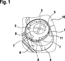
図1には、本発明による圧力補償エレメントの1実施形態が示されており、この実施形態では、底面3と円筒形の壁4とを備えたポット形のカバーエレメント1が設けられている。このカバーエレメント1は、挿入されるアダプタ2を認識できるようにするために、透明に示されている。アダプタ2は弾性的な材料から成っていて、連続した孔5を有しており、この孔5の、カバーエレメント1の底面3に向けられた開口は、十字形のウェブ9を有している。図3との関連においてさらに詳しく述べるこれらのウェブ9は、開口を覆うフィルタエレメント(ここでは図示せず)を支持するために働く。
DESCRIPTION OF THE EMBODIMENTS FIG. 1 shows an embodiment of a pressure compensation element according to the invention, in which a pot-
アダプタ2は、その軸方向の孔5の下端部で、空気抜きされる伝動装置ハウジング10に、特に孔5内に進入する空気抜きドーム(図3参照)に載せられている。さらにアダプタ2はカバーエレメント1内に位置決めされていて、半径方向で固定されている。アダプタ2は、ほぼ円筒形の外輪郭を有する中央部分を有しており、しかしながらこの中央部分からは、1つの突出部6が突出しており、その結果アダプタ2の外壁は、全体として非対称的な外輪郭を有している。カバーエレメント1内におけるアダプタ2の固定時に、突出部6の外側面8は、カバーエレメント1の(壁4の)内壁に押し付けられる。さらに特に、アダプタ2の中央部分の、外側面8とは反対側に位置する背側の面もまた、カバーエレメント1の(壁4の)内壁に押し付けられる。アダプタ外壁とカバーエレメント内壁との間における間隔が横方向において突出部6から離れる方向において徐々に狭くなっている場合でも、いずれにせよ突出部6の左右には、十分に大きな空気通路7が残されており、これによって空気抜きドームと孔5と、該孔5の上端部とカバーエレメント1の閉鎖された端部(底面3)との間の中間室と、圧力補償エレメントの閉鎖されていない下側(伝動装置ハウジング側)の周囲との間における空気通路における空気交換を保証することができる。挿入された状態において、カバーエレメント1の底領域に設けられた支台は、アダプタ2の底側の端面と接触し、これにより前記中間室を形成することができる。(中間室は、後で図4との関連において述べるラビリンス系によっても形成することができる。)
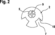
非対称的なアダプタ2の所要構造スペース、ひいては圧力補償エレメントの所要構造スペースは、例えば図3に示されているような、全周にわたって分配配置された4つの突出部12を備えた対称的なアダプタに比べて、明らかに小さい。機械的な安定性に関して、図2に示された非対称的なアダプタ2の同様に小型の別の実施形態は、さらに有利である。図2に示されたこのアダプタ2では、アダプタ外壁とカバーエレメント内壁との間における空気通路7は、ただ1つの突出部の側方又は複数の突出部の間に設けられているのではなく、この場合空気通路7は、2つの溝7の形で、内方にアダプタ2の中央部分に向かって設けられている。さらにこの非対称的な別の実施形態では、アダプタ2はカバーエレメント1内において特に正確に位置決め可能であり、かつ図1に示されているような、水が進入するおそれのある間隙11が形成されることはない。
The
The required structure space of the
図1及び図2から分かるように、カバーエレメント1内に挿入されたアダプタ2の孔5は、非対称的なアダプタ2もしくはカバーエレメント1に対して偏心的に配置されており、その結果、周囲に対する空気抜きドーム13もしくは圧力補償エレメントの相対ポジションにおいて別の間隙が有利に生ぜしめられる。
As can be seen from FIGS. 1 and 2, the
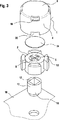
図3に示された本発明による圧力補償エレメントの別の実施形態では、例えば4つの突出部12がアダプタ2の中央部分の周囲に均一に分配配置されて設けられており、その結果外輪郭に関して全体として対称的なアダプタ2が得られる。空気抜きドーム13は、図面を見易くする理由から選択された図示とは異なり、図3にのみ略示された伝動装置ハウジング10と一体に構成された典型的な構成を有している。
In another embodiment of the pressure compensation element according to the invention shown in FIG. 3, for example, four
対称的なアダプタ2と、通気性のフィルタエレメントであるダイヤフラム14と、カバーエレメント1とから成る圧力補償エレメントは、空気抜きドーム13に装着される。空気抜きドーム13は、丸い内側横断面を有していて伝動装置ハウジング10に向けられた区分16と、方形の内側横断面を有していて圧力補償エレメントに向けられた区分17とを有している。このような形状付与もしくはこのような形状付与の配置形式は、不均一な表面張力による水のブリッジを回避するために適しており、その結果(特に圧力補償エレメントによって空気抜きドーム13がなお閉鎖されていない場合に)生じるおそれのある水の進入が阻止される。
A pressure compensation element comprising a
アダプタ2は弾性材料から成っており、その結果アダプタ2はその孔5を用いて、容易にドーム13に押し嵌めるもしくは被せ嵌めることができる。アダプタ2の上端面にはフィルタエレメントとして、水は通さないつまり防水性であるが空気透過性の多孔性のダイヤフラム14が固定されており、このダイヤフラム14は、アダプタ2の孔5内に十字形に設けられたウェブ9によって支持されている。これによってダイヤフラム14が折れることは阻止される。十字形のウェブ9は図3に示されているように、容易に湾曲することができるので、ビードが形成されることはなく、水は流出することができる。
The
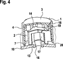
カバーエレメント1の底面3とカバーエレメント1の壁との間の移行領域には、少なくとも1つの切欠き18が設けられており、この切欠き18は、カバーエレメント1の内壁とアダプタ2の外壁との間における空気通路7のために働かない、カバーエレメント1のセグメントに配置されている。逆様に取り付けられた圧力補償エレメント内に溜まった水は、切欠き18を通って流出することができる。
At least one
典型的には圧力補償エレメントは、空気抜きを可能にするため及び水が毛管現象によって上昇しないようにするために、完全にはハウジング10に載置もしくは接触していない。このような場合でも、空気抜き及び水の流出は、カバーエレメント1の壁4の自由端部に少なくとも1つの切欠き20が設けられていることによって保証することができ、この切欠き20もしくはこれらの切欠き20はそれぞれ、所属の切欠き18と同じセグメントに配置されている。
Typically, the pressure compensation element is not completely mounted or in contact with the
ダイヤフラム14及び空気通路全体は、カバーエレメント1によって保護される。このカバーエレメント1は、図4に示されているようなラビリンス系を有しており、このラビリンス系は、常に空気の供給及び排出、鋭い対象物の侵入防止、塵埃もしくは汚れの侵入防止及び水の流出防止を、取付け状態とは無関係に保証する。さらにカバーエレメント1がアダプタ2にプレス嵌めされ、これによって伝動装置ハウジング10からの解離が阻止される。詳しく述べると、カバーエレメント1の底面3とフィルタエレメント14との間の中間室にラビリンス系が設けられており、このラビリンス系はそれぞれ、各切欠き18に対向して配置された壁エレメント19を有しており、これらの壁エレメント19は、外部から中間室の中心へのダイレクトな接近をブロックしている。この壁エレメント19は中実な部材であり、コラムもしくは柱体としてダイヤフラム14を押圧し、かつ同時にアダプタ2と底面3との間における端面側の中間室を支持している。切欠き18もしくはラビリンス系を備えたこのような構成は、図1に示された非対称的な実施形態との関連においても有利に使用することができる。
The
コスト的にリーズナブルな空気抜きバリエーションでは、ワイパモータの伝動装置ハウジング10から進出する被駆動軸(ハウジング10における相応な開口Aだけを示す図5参照)が、ワイパモータの圧力補償のために働く中空軸として形成されており、この中空軸の、伝動装置ハウジング10から進出している端部に、圧力補償エレメントが取り付けられている。
In a reasonable air vent variation, the driven shaft (see FIG. 5 showing only the corresponding opening A in the housing 10) that extends from the
図6には、取付け開口(ここでは見えない)又は空気抜きドームを備えた伝動装置ハウジング10と、この伝動装置ハウジング10に装着された圧力補償エレメントとから成る別の配置形式が示されており、この場合圧力補償エレメントは例えば、カバーエレメント1に6つの切欠き18(及び相応にアダプタ2における6つの突出部12)を備えている。これまでの実施形態とは異なり、伝動装置ハウジング10からの圧力補償エレメントの解離は、摩擦力結合(プレス嵌め)によって阻止されるのみならず、付加的にカバーエレメント1における係止フック21及び伝動装置ハウジング10における係止突起22を介した形状結合によっても、阻止される。
FIG. 6 shows another arrangement of a
Claims (11)
底面(3)と壁(4)とを備えたポット形のカバーエレメント(1)と、
該カバーエレメント(1)に挿入された弾性材料製のアダプタ(2)とが設けられていて、該アダプタ(2)が、連続した孔(5)を有していて、該孔(5)の、カバーエレメント(1)の底面(3)に向けられた開口が、フィルタエレメント(14)によって覆われており、
カバーエレメント(1)の内壁とアダプタ(2)の外壁との間及びカバーエレメントの底面(3)とアダプタ(2)の孔(5)との間に、空気通路(7)が形成されており、
アダプタ(2)が、その周面にただ1つの突出部(6)を備えて形成された外輪郭を有していて、アダプタ(2)の周面の中心が、前記孔(5)の中心に対して偏心しており、突出部(6)がカバーエレメント(1)の内壁と接触していて、突出部(6)の両側に空気通路(7)が形成されていることを特徴とする、ハウジング用の圧力補償エレメント。A pressure compensation element connectable to an air vent dome provided in a mounting opening of the housing,
A pot-shaped cover element (1) with a bottom surface (3) and a wall (4);
An adapter (2) made of an elastic material inserted into the cover element (1), the adapter (2) has a continuous hole (5), and the adapter of the hole (5) The opening directed to the bottom surface (3) of the cover element (1) is covered by the filter element (14),
Air passages (7) are formed between the inner wall of the cover element (1) and the outer wall of the adapter (2) and between the bottom surface (3) of the cover element and the hole (5) of the adapter (2). ,
Adapter (2), its one projection but the other on the peripheral surface (6) have an outer contour which is formed with a center of the peripheral surface of the adapter (2) comprises holes (5) It is eccentric with respect to the center , the protrusion (6) is in contact with the inner wall of the cover element (1), and air passages (7) are formed on both sides of the protrusion (6). The pressure compensation element for the housing.
底面(3)と壁(4)とを備えたポット形のカバーエレメント(1)と、
該カバーエレメント(1)に挿入された弾性材料製のアダプタ(2)とが設けられていて、該アダプタ(2)が、連続した孔(5)を有していて、該孔(5)の、カバーエレメント(1)の底面(3)に向けられた開口が、フィルタエレメント(14)によって覆われており、
カバーエレメント(1)の内壁とアダプタ(2)の外壁との間及びカバーエレメントの底面(3)とアダプタ(2)の孔(5)との間に、空気通路(7)が形成されており、
アダプタ(2)が、該アダプタの周面に互いに間隔をおいて位置する2つの軸方向の溝(15)を有する外輪郭を有していて、アダプタ(2)の周面の中心が、前記孔(5)の中心に対して偏心しており、この外輪郭が2つの溝(15)の領域において、カバーエレメント(1)の内壁と接触しておらず、両方の溝(15)において空気通路(7)が形成されていることを特徴とする、ハウジング用の圧力補償エレメント。A pressure compensation element connectable to an air vent dome provided in a mounting opening of the housing,
A pot-shaped cover element (1) with a bottom surface (3) and a wall (4);
An adapter (2) made of an elastic material inserted into the cover element (1), the adapter (2) has a continuous hole (5), and the adapter of the hole (5) The opening directed to the bottom surface (3) of the cover element (1) is covered by the filter element (14),
Air passages (7) are formed between the inner wall of the cover element (1) and the outer wall of the adapter (2) and between the bottom surface (3) of the cover element and the hole (5) of the adapter (2). ,
The adapter (2) has an outer contour with two axial grooves (15) spaced from each other on the peripheral surface of the adapter, the center of the peripheral surface of the adapter (2) being Eccentric with respect to the center of the hole (5) , this outer contour is not in contact with the inner wall of the cover element (1) in the region of the two grooves (15) and air in both grooves (15) A pressure compensation element for a housing, characterized in that a passage (7) is formed.
底面(3)と壁(4)とを備えたポット形のカバーエレメント(1)と、
該カバーエレメント(1)に挿入された弾性材料製のアダプタ(2)とが設けられていて、該アダプタ(2)が、連続した孔(5)を有していて、該孔(5)の、カバーエレメント(1)の底面(3)に向けられた開口が、フィルタエレメント(14)によって覆われており、
カバーエレメント(1)の内壁とアダプタ(2)の外壁との間及びカバーエレメントの底面(3)とアダプタ(2)の孔(5)との間に、空気通路(7)が形成されており、
カバーエレメント(1)の壁(4)への底面(3)の移行領域に、少なくとも1つの切欠き(18)が設けられており、該切欠き(18)が、カバーエレメント(1)の内壁とアダプタ(2)の外壁との間における空気通路(7)に対して周方向でずらされて、カバーエレメント(1)の周囲の円弧区分に配置されていることを特徴とする、ハウジング用の圧力補償エレメント。A pressure compensation element connectable to an air vent dome provided in a mounting opening of the housing,
A pot-shaped cover element (1) with a bottom surface (3) and a wall (4);
An adapter (2) made of an elastic material inserted into the cover element (1), the adapter (2) has a continuous hole (5), and the adapter of the hole (5) The opening directed to the bottom surface (3) of the cover element (1) is covered by the filter element (14),
Air passages (7) are formed between the inner wall of the cover element (1) and the outer wall of the adapter (2) and between the bottom surface (3) of the cover element and the hole (5) of the adapter (2). ,
At least one notch (18) is provided in the transition region of the bottom surface (3) to the wall (4) of the cover element (1), the notch (18) being the inner wall of the cover element (1). For the housing, characterized in that it is circumferentially displaced with respect to the air passage (7) between the cover and the outer wall of the adapter (2) and arranged in an arc segment around the cover element (1) Pressure compensation element.
Applications Claiming Priority (5)
| Application Number | Priority Date | Filing Date | Title |
|---|---|---|---|
| DE102006061280 | 2006-12-22 | ||
| DE102006061280.9 | 2006-12-22 | ||
| DE102007012703A DE102007012703A1 (en) | 2006-12-22 | 2007-03-16 | Pressure compensation element for a housing and motor vehicle electrical component with such a pressure compensation element |
| DE102007012703.2 | 2007-03-16 | ||
| PCT/EP2007/061507 WO2008077667A2 (en) | 2006-12-22 | 2007-10-26 | Pressure compensation element for a housing and electrical automotive component comprising said pressure compensation element |
Publications (3)
| Publication Number | Publication Date |
|---|---|
| JP2010513813A JP2010513813A (en) | 2010-04-30 |
| JP2010513813A5 JP2010513813A5 (en) | 2012-07-05 |
| JP5065409B2 true JP5065409B2 (en) | 2012-10-31 |
Family
ID=39431921
Family Applications (1)
| Application Number | Title | Priority Date | Filing Date |
|---|---|---|---|
| JP2009541933A Expired - Fee Related JP5065409B2 (en) | 2006-12-22 | 2007-10-26 | Pressure compensation element for a housing, and automotive electrical component comprising such a pressure compensation element |
Country Status (10)
| Country | Link |
|---|---|
| EP (2) | EP2127509B1 (en) |
| JP (1) | JP5065409B2 (en) |
| KR (1) | KR101381129B1 (en) |
| CN (1) | CN101584260B (en) |
| AT (1) | ATE502513T1 (en) |
| BR (1) | BRPI0720432A2 (en) |
| DE (2) | DE102007012703A1 (en) |
| PL (1) | PL2127509T3 (en) |
| RU (1) | RU2440903C2 (en) |
| WO (1) | WO2008077667A2 (en) |
Families Citing this family (34)
| Publication number | Priority date | Publication date | Assignee | Title |
|---|---|---|---|---|
| DE102008001591A1 (en) * | 2008-05-06 | 2009-11-12 | Robert Bosch Gmbh | Housing for a drive device, drive device and method for checking the tightness of a pressure compensation membrane |
| US8430114B2 (en) * | 2009-09-08 | 2013-04-30 | GM Global Technology Operations LLC | Hydrophobic vent assembly |
| DE102009054038A1 (en) * | 2009-11-20 | 2011-05-26 | Neoperl Gmbh | Water-bearing pipe section with a ventilation duct |
| DE102010015610B4 (en) | 2010-04-19 | 2022-08-25 | Axel R. Hidde | Sealing ring with diaphragm valve |
| DE202010013887U1 (en) * | 2010-10-02 | 2012-01-10 | Hella Kgaa Hueck & Co. | Housing unit for mechanical, electromechanical and electrotechnical components |
| DE102011010640A1 (en) * | 2011-02-09 | 2012-08-09 | Emitec France S.A.S | Feed unit for conveying reducing agent |
| DE102011012630B4 (en) * | 2011-02-28 | 2015-03-19 | Sew-Eurodrive Gmbh & Co Kg | Compensation element, drive and method for producing a compensation element |
| CN102723801A (en) * | 2011-03-30 | 2012-10-10 | 比亚迪股份有限公司 | Internal and external pressure balance structure and motor comprising the same |
| EP2702844B1 (en) * | 2011-04-27 | 2018-03-21 | Pierburg Pump Technology GmbH | Housing unit for electrical components for use in the automobile sector |
| DE102011112576A1 (en) | 2011-09-08 | 2013-03-14 | GM Global Technology Operations LLC (n. d. Gesetzen des Staates Delaware) | Pressure compensation element connected to vent pipe of device housing of motor vehicle component, gas reservoir chamber that is fluidly connected to environment by one-way valve whose forward direction is directed to environment |
| DE102012220368A1 (en) | 2012-11-08 | 2014-05-08 | Magna Powertrain Ag & Co. Kg | Drive unit for use in hybrid drive system for hybrid car, has oil-filled units arranged at front ends of rotor, and labyrinth seal arranged for air exchange and facilitating air exchange of oil-filled units opened in space |
| JP2014154408A (en) * | 2013-02-12 | 2014-08-25 | Stanley Electric Co Ltd | Vehicular lighting fixture |
| DE202013006741U1 (en) | 2013-07-26 | 2014-10-27 | GM Global Technology Operations, LLC (n.d. Ges. d. Staates Delaware) | Gearbox with hollow shaft |
| DE102013109260A1 (en) * | 2013-08-27 | 2015-03-05 | R.Stahl Schaltgeräte GmbH | Housing part for an explosion-proof housing with a porous body |
| DE102013111992B3 (en) * | 2013-10-30 | 2015-01-22 | Günther Spelsberg GmbH & Co. KG | Housing with ventilation element |
| DE102014206735A1 (en) * | 2014-04-08 | 2015-10-08 | Continental Automotive Gmbh | Pressure compensation element for a housing |
| WO2016076351A1 (en) | 2014-11-14 | 2016-05-19 | 三菱電機株式会社 | Waterproof ventilator and electronic device apparatus |
| KR102401681B1 (en) * | 2015-02-18 | 2022-05-24 | 지브이에스 에스.피.에이. | Elements for improved ventilation of housings housing electrical, electronic, mechanical or similar devices |
| DE102015209468A1 (en) * | 2015-05-22 | 2016-11-24 | Continental Teves Ag & Co. Ohg | Arrangement for the protection of electronics against interference radiation |
| DE102015218064B4 (en) * | 2015-09-21 | 2017-09-14 | Conti Temic Microelectronic Gmbh | transmission assembly |
| JP6542109B2 (en) * | 2015-11-20 | 2019-07-10 | 住友重機械工業株式会社 | Air breather |
| DE102016202965B3 (en) * | 2016-02-25 | 2017-08-31 | Audi Ag | Pressure equalization device for a housing, in particular a motor vehicle, and component for a motor vehicle |
| DE102016208276A1 (en) | 2016-05-13 | 2017-11-16 | Mahle International Gmbh | setting device |
| CN107041082A (en) * | 2016-11-18 | 2017-08-11 | 江门崇达电路技术有限公司 | The PCB process for pressing of dissymmetrical structure |
| JP6683170B2 (en) * | 2017-04-27 | 2020-04-15 | 株式会社アドヴィックス | Motor device |
| DE102018107678A1 (en) * | 2018-03-29 | 2019-10-02 | Automotive Lighting Reutlingen Gmbh | Micro-mirror having light module for a motor vehicle headlight |
| DE102018009382A1 (en) * | 2018-11-30 | 2020-06-04 | Dräger Safety AG & Co. KGaA | Fastening device for a sensor housing |
| DE102019103431B3 (en) * | 2019-02-12 | 2020-04-09 | Hugo Benzing Gmbh & Co. Kg | Pressure relief valve for relieving pressure generated in a cell-like cavity, such as a battery cell |
| DE102019114055A1 (en) * | 2019-05-27 | 2020-12-03 | Schaeffler Technologies AG & Co. KG | Pressure compensation element |
| DE202020005406U1 (en) | 2020-11-12 | 2022-02-21 | Konzelmann Gmbh | pressure equalization device |
| DE102020131994A1 (en) | 2020-11-17 | 2022-05-19 | Stego-Holding Gmbh | pressure compensation element |
| DE102021116815A1 (en) * | 2021-06-30 | 2023-01-05 | Marelli Automotive Lighting Reutlingen (Germany) GmbH | Ventilation module for a motor vehicle lighting device |
| WO2024002469A1 (en) * | 2022-06-28 | 2024-01-04 | Pierburg Gmbh | Blower |
| DE102022003912A1 (en) | 2022-10-21 | 2024-05-02 | BRUSS Sealing Systems GmbH | Ventilation module for a transmission of a particularly electrically powered motor vehicle |
Family Cites Families (8)
| Publication number | Priority date | Publication date | Assignee | Title |
|---|---|---|---|---|
| JPS59169472U (en) * | 1983-04-28 | 1984-11-13 | 日産自動車株式会社 | Breather structure of electrical components |
| DE3707050C2 (en) * | 1987-03-05 | 1995-09-28 | Bosch Gmbh Robert | Electrical switching device, in particular for motor vehicles |
| FR2631736B1 (en) * | 1988-05-20 | 1993-10-29 | Bosch Gmbh Robert | PRESSURE COMPENSATION ELEMENT FOR AN ELECTRICAL DISTRIBUTION APPARATUS |
| EP0377067A1 (en) * | 1989-01-05 | 1990-07-11 | W.L. Gore & Associates GmbH | Shut off device for a sealed housing |
| JP4043674B2 (en) * | 1999-11-18 | 2008-02-06 | 日東電工株式会社 | Ventilation cap and outdoor lamp, automobile lamp and automobile electrical parts using the same |
| JP2003008247A (en) * | 2001-06-19 | 2003-01-10 | Tdk Corp | Mounting structure for seal cap |
| US20060113236A1 (en) * | 2004-09-13 | 2006-06-01 | Andrew Dahlgren | Breather filter |
| DE102006053113A1 (en) * | 2006-11-10 | 2008-05-15 | Robert Bosch Gmbh | Pressure compensation element for a housing |
-
2007
- 2007-03-16 DE DE102007012703A patent/DE102007012703A1/en not_active Withdrawn
- 2007-10-26 PL PL07821870T patent/PL2127509T3/en unknown
- 2007-10-26 DE DE502007006749T patent/DE502007006749D1/en active Active
- 2007-10-26 EP EP07821870A patent/EP2127509B1/en not_active Not-in-force
- 2007-10-26 JP JP2009541933A patent/JP5065409B2/en not_active Expired - Fee Related
- 2007-10-26 AT AT07821870T patent/ATE502513T1/en active
- 2007-10-26 EP EP10186637A patent/EP2273860B1/en not_active Not-in-force
- 2007-10-26 KR KR1020097012946A patent/KR101381129B1/en not_active IP Right Cessation
- 2007-10-26 CN CN2007800477589A patent/CN101584260B/en not_active Expired - Fee Related
- 2007-10-26 RU RU2009127859/11A patent/RU2440903C2/en not_active IP Right Cessation
- 2007-10-26 WO PCT/EP2007/061507 patent/WO2008077667A2/en active Application Filing
- 2007-10-26 BR BRPI0720432-9A patent/BRPI0720432A2/en not_active IP Right Cessation
Also Published As
| Publication number | Publication date |
|---|---|
| ATE502513T1 (en) | 2011-04-15 |
| EP2273860A1 (en) | 2011-01-12 |
| JP2010513813A (en) | 2010-04-30 |
| WO2008077667A2 (en) | 2008-07-03 |
| RU2440903C2 (en) | 2012-01-27 |
| EP2127509A2 (en) | 2009-12-02 |
| BRPI0720432A2 (en) | 2014-01-07 |
| PL2127509T3 (en) | 2011-08-31 |
| KR20090094100A (en) | 2009-09-03 |
| WO2008077667A3 (en) | 2009-04-16 |
| DE502007006749D1 (en) | 2011-04-28 |
| EP2127509B1 (en) | 2011-03-16 |
| RU2009127859A (en) | 2011-01-27 |
| KR101381129B1 (en) | 2014-04-04 |
| EP2273860B1 (en) | 2012-09-19 |
| CN101584260B (en) | 2012-01-25 |
| CN101584260A (en) | 2009-11-18 |
| DE102007012703A1 (en) | 2008-06-26 |
Similar Documents
| Publication | Publication Date | Title |
|---|---|---|
| JP5065409B2 (en) | Pressure compensation element for a housing, and automotive electrical component comprising such a pressure compensation element | |
| KR101270331B1 (en) | Ventilation member | |
| US5558244A (en) | Oil reservoir having a cap with cylindrical baffles defining labyrinth passage | |
| JP4295230B2 (en) | Thermostat valve that forms a unit with a lid-like housing part | |
| EP3288354B1 (en) | Waterproof enclosure | |
| US20180263126A1 (en) | Pressure-equalizing element and housing containing same | |
| JP2005121230A (en) | System for fixing rolling bearing in axial direction | |
| JP6474284B2 (en) | Breather, motor with reduction gear, and wiper motor | |
| JP6542109B2 (en) | Air breather | |
| JP2007336729A (en) | Electrical connection box | |
| JP2019044887A (en) | Supporting structure of parking pole | |
| CN111164329B (en) | Thrust sliding bearing | |
| JP2006007140A (en) | Filtering device | |
| JP2005325937A (en) | Piston for automatic transmission | |
| JP5792035B2 (en) | pressure switch | |
| KR101701473B1 (en) | ventilation cap for car | |
| JP3806587B2 (en) | Steering device mounting structure | |
| JP2019100366A (en) | Breather plug of vehicle | |
| KR100320534B1 (en) | Multi function switch of vehicle | |
| JP2007064397A (en) | Constant velocity universal joint | |
| KR200203478Y1 (en) | Roll stopper structure for engine mounting | |
| US6505540B2 (en) | Control valve retaining element | |
| WO2016076208A1 (en) | Neutral start switch | |
| US20040222623A1 (en) | Sealing assembly for a steering column assembly | |
| KR930004851Y1 (en) | Start motor |
Legal Events
| Date | Code | Title | Description |
|---|---|---|---|
| RD04 | Notification of resignation of power of attorney |
Free format text: JAPANESE INTERMEDIATE CODE: A7424 Effective date: 20101228 |
|
| A131 | Notification of reasons for refusal |
Free format text: JAPANESE INTERMEDIATE CODE: A131 Effective date: 20111118 |
|
| A601 | Written request for extension of time |
Free format text: JAPANESE INTERMEDIATE CODE: A601 Effective date: 20120220 |
|
| A602 | Written permission of extension of time |
Free format text: JAPANESE INTERMEDIATE CODE: A602 Effective date: 20120227 |
|
| A521 | Request for written amendment filed |
Free format text: JAPANESE INTERMEDIATE CODE: A523 Effective date: 20120517 |
|
| A524 | Written submission of copy of amendment under article 19 pct |
Free format text: JAPANESE INTERMEDIATE CODE: A524 Effective date: 20120517 |
|
| TRDD | Decision of grant or rejection written | ||
| A01 | Written decision to grant a patent or to grant a registration (utility model) |
Free format text: JAPANESE INTERMEDIATE CODE: A01 Effective date: 20120711 |
|
| A01 | Written decision to grant a patent or to grant a registration (utility model) |
Free format text: JAPANESE INTERMEDIATE CODE: A01 |
|
| A61 | First payment of annual fees (during grant procedure) |
Free format text: JAPANESE INTERMEDIATE CODE: A61 Effective date: 20120809 |
|
| R150 | Certificate of patent or registration of utility model |
Ref document number: 5065409 Country of ref document: JP Free format text: JAPANESE INTERMEDIATE CODE: R150 Free format text: JAPANESE INTERMEDIATE CODE: R150 |
|
| FPAY | Renewal fee payment (event date is renewal date of database) |
Free format text: PAYMENT UNTIL: 20150817 Year of fee payment: 3 |
|
| R250 | Receipt of annual fees |
Free format text: JAPANESE INTERMEDIATE CODE: R250 |
|
| R250 | Receipt of annual fees |
Free format text: JAPANESE INTERMEDIATE CODE: R250 |
|
| R250 | Receipt of annual fees |
Free format text: JAPANESE INTERMEDIATE CODE: R250 |
|
| R250 | Receipt of annual fees |
Free format text: JAPANESE INTERMEDIATE CODE: R250 |
|
| LAPS | Cancellation because of no payment of annual fees |