EP2273860B1 - Pressure compensation element for a housing and electrical automotive component comprising said pressure compensation element - Google Patents
Pressure compensation element for a housing and electrical automotive component comprising said pressure compensation element Download PDFInfo
- Publication number
- EP2273860B1 EP2273860B1 EP10186637A EP10186637A EP2273860B1 EP 2273860 B1 EP2273860 B1 EP 2273860B1 EP 10186637 A EP10186637 A EP 10186637A EP 10186637 A EP10186637 A EP 10186637A EP 2273860 B1 EP2273860 B1 EP 2273860B1
- Authority
- EP
- European Patent Office
- Prior art keywords
- pressure compensation
- adapter
- wall
- compensation element
- cover element
- Prior art date
- Legal status (The legal status is an assumption and is not a legal conclusion. Google has not performed a legal analysis and makes no representation as to the accuracy of the status listed.)
- Not-in-force
Links
Images

Classifications
-
- H—ELECTRICITY
- H02—GENERATION; CONVERSION OR DISTRIBUTION OF ELECTRIC POWER
- H02K—DYNAMO-ELECTRIC MACHINES
- H02K5/00—Casings; Enclosures; Supports
- H02K5/02—Casings or enclosures characterised by the material thereof
-
- F—MECHANICAL ENGINEERING; LIGHTING; HEATING; WEAPONS; BLASTING
- F21—LIGHTING
- F21V—FUNCTIONAL FEATURES OR DETAILS OF LIGHTING DEVICES OR SYSTEMS THEREOF; STRUCTURAL COMBINATIONS OF LIGHTING DEVICES WITH OTHER ARTICLES, NOT OTHERWISE PROVIDED FOR
- F21V31/00—Gas-tight or water-tight arrangements
- F21V31/03—Gas-tight or water-tight arrangements with provision for venting
-
- F—MECHANICAL ENGINEERING; LIGHTING; HEATING; WEAPONS; BLASTING
- F16—ENGINEERING ELEMENTS AND UNITS; GENERAL MEASURES FOR PRODUCING AND MAINTAINING EFFECTIVE FUNCTIONING OF MACHINES OR INSTALLATIONS; THERMAL INSULATION IN GENERAL
- F16H—GEARING
- F16H57/00—General details of gearing
- F16H57/02—Gearboxes; Mounting gearing therein
- F16H57/027—Gearboxes; Mounting gearing therein characterised by means for venting gearboxes, e.g. air breathers
-
- F—MECHANICAL ENGINEERING; LIGHTING; HEATING; WEAPONS; BLASTING
- F16—ENGINEERING ELEMENTS AND UNITS; GENERAL MEASURES FOR PRODUCING AND MAINTAINING EFFECTIVE FUNCTIONING OF MACHINES OR INSTALLATIONS; THERMAL INSULATION IN GENERAL
- F16K—VALVES; TAPS; COCKS; ACTUATING-FLOATS; DEVICES FOR VENTING OR AERATING
- F16K24/00—Devices, e.g. valves, for venting or aerating enclosures
- F16K24/04—Devices, e.g. valves, for venting or aerating enclosures for venting only
-
- F—MECHANICAL ENGINEERING; LIGHTING; HEATING; WEAPONS; BLASTING
- F21—LIGHTING
- F21S—NON-PORTABLE LIGHTING DEVICES; SYSTEMS THEREOF; VEHICLE LIGHTING DEVICES SPECIALLY ADAPTED FOR VEHICLE EXTERIORS
- F21S45/00—Arrangements within vehicle lighting devices specially adapted for vehicle exteriors, for purposes other than emission or distribution of light
- F21S45/30—Ventilation or drainage of lighting devices
- F21S45/33—Ventilation or drainage of lighting devices specially adapted for headlamps
-
- H—ELECTRICITY
- H02—GENERATION; CONVERSION OR DISTRIBUTION OF ELECTRIC POWER
- H02K—DYNAMO-ELECTRIC MACHINES
- H02K5/00—Casings; Enclosures; Supports
- H02K5/04—Casings or enclosures characterised by the shape, form or construction thereof
- H02K5/06—Cast metal casings
-
- H—ELECTRICITY
- H02—GENERATION; CONVERSION OR DISTRIBUTION OF ELECTRIC POWER
- H02K—DYNAMO-ELECTRIC MACHINES
- H02K5/00—Casings; Enclosures; Supports
- H02K5/04—Casings or enclosures characterised by the shape, form or construction thereof
- H02K5/10—Casings or enclosures characterised by the shape, form or construction thereof with arrangements for protection from ingress, e.g. water or fingers
-
- H—ELECTRICITY
- H05—ELECTRIC TECHNIQUES NOT OTHERWISE PROVIDED FOR
- H05K—PRINTED CIRCUITS; CASINGS OR CONSTRUCTIONAL DETAILS OF ELECTRIC APPARATUS; MANUFACTURE OF ASSEMBLAGES OF ELECTRICAL COMPONENTS
- H05K5/00—Casings, cabinets or drawers for electric apparatus
- H05K5/02—Details
- H05K5/0213—Venting apertures; Constructional details thereof
- H05K5/0216—Venting plugs comprising semi-permeable membranes
-
- H—ELECTRICITY
- H02—GENERATION; CONVERSION OR DISTRIBUTION OF ELECTRIC POWER
- H02K—DYNAMO-ELECTRIC MACHINES
- H02K2205/00—Specific aspects not provided for in the other groups of this subclass relating to casings, enclosures, supports
- H02K2205/09—Machines characterised by drain passages or by venting, breathing or pressure compensating means
Definitions
- At least one recess is provided at the free end of the wall of the cover element to improve the water drainage or the air exchange, even when the pressure compensation element is fitted tightly against a housing, and each arranged in the same segment of the circumference as the associated recess is.
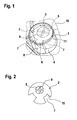
- FIG. 1 an embodiment of a pressure compensation element is shown, in the first a cup-shaped cover member 1 with a bottom surface 3 and a cylindrical wall 4 can be seen.
- the cover element 1 is in FIG. 1 shown transparent to recognize the inserted adapter 2 can.
- the adapter 2 is made of elastic material and has a through hole 5, the opening directed to the bottom surface 3 of the cover element 1 has cross-shaped webs 9.
- the webs 9 serve, as related to FIG. 3 will be described in more detail, to support a filter covering the opening, not shown here.
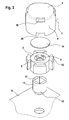
- FIG. 3 With regard to the mechanical stability is even more advantageous in FIG. 2 shown schematically, also small-sized embodiment of an asymmetric adapter 2, wherein the air passage 7 between the adapter outer wall and the cover element inner wall is not made laterally from a single projection or between a plurality of projections, but in which the air passage 7 - in the form of two Grooves 15 - is moved almost to the inside in the central part of the adapter 2.
- the adapter 2 can be positioned particularly accurately in the cover element 1 and that no gaps 11, cf. FIG. 1 , are formed, in which could hold water.
- the bore 5 of the inserted into the cover member 1 adapter 2 can be arranged eccentrically to the asymmetrical adapter 2 and the cover element 1, so that advantageously results in a further margin in the relative position of the venting dome 13 and pressure compensation element to the environment.
- the adapter 2 is made of elastic material, so that it can be relatively easily slipped or pressed with its bore 5 on the dome 13.
- a porous, air-permeable and water-impermeable membrane 14 is fastened as a filter element, wherein the membrane is supported by cross-shaped webs 9 mounted in the bore 5 of the adapter 2.
- the cross-shaped webs 9 can, as in FIG. 3 indicated, be slightly curved, so that no beading occurs, but the water can flow.
- This wall element 19 is a relatively solid part, which presses like a column on the membrane 14 and at the same time supports the frontal space between the adapter 2 and the bottom surface 3.
- the embodiment described with the recesses 18 and the labyrinth system is also in connection with the in FIG. 1 described asymmetrical embodiments can be used advantageously.
Abstract
Description
Die Erfindung betrifft ein Druckausgleichselement, welches an einer Anbringöffnung, insbesondere Entlüftungsdom, eines Gehäuses anbringbar ist. Die Erfindung betrifft außerdem eine Kraftfahrzeug-Elektrokomponente, insbesondere ein Getriebegehäuse eines Wischermotors, die ein derartiges Druckausgleichselement umfasst.The invention relates to a pressure compensation element which can be attached to an attachment opening, in particular ventilation dome, of a housing. The invention also relates to a motor vehicle electrical component, in particular a transmission housing of a wiper motor, which comprises such a pressure compensation element.
Bei vielen Elektrokomponenten, die zur Abschottung gegen Umwelteinflüsse ein geschlossenes Gehäuse, z. B. das Getriebegehäuse eines Wischermotors, aufweisen, ist es erforderlich, im Gehäuse eine Öffnung vorzusehen, die beim Auftreten einer Temperaturdifferenz einen Druckausgleich zwischen Innen und Außen ermöglicht. Dieses Entlüftungsorgan, typischerweise ein kleiner, in die Gehäusewand integrierter, offener Zylinder, ein so genannter Entlüftungsdom, wird häufig mit weiteren Komponenten, insbesondere einem Labyrinth, einer Membran und einer auf das aus dem Gehäuse herausragende Ende des Doms aufsetzbaren Schutzkappe, ergänzt. Diese Zusatzkomponenten der Druckausgleichsanordnung sollen den mit dem Luftaustausch grundsätzlich auch möglich gewordenen Eintritt von Wasser, Staub usw. durch die Gehäuseöffnung in den Innenraum des Gehäuses weitestgehend verhindern.For many electrical components, the foreclosure against environmental influences a closed housing, eg. As the gear housing of a wiper motor, have, it is necessary to provide an opening in the housing, which allows for the occurrence of a temperature difference pressure equalization between inside and outside. This venting device, typically a small, in the housing wall integrated, open cylinder, a so-called vent dome, is often supplemented with other components, in particular a labyrinth, a membrane and an attachable to the protruding from the housing end of the dome cap. These additional components of the pressure compensation arrangement should largely prevent the entry of water, dust, etc. through the housing opening into the interior of the housing that has become possible in principle with the air exchange.
Druckausgleichsanordnungen für Gehäuse sind in zahlreichen Ausführungsformen bekannt. Aus der
Die bekannte luftdurchlässige Kappe kann aber nicht, insbesondere nicht in allen Einbausituationen, alle an sie zu stellenden Anforderungen erfüllen. Da die Einbauposition, beispielsweise an einer bestimmten Stelle des Getriebegehäuses, bzw. auch die Einbaulage in der Praxis meist vorgegeben sind, sollte die Kappe einerseits größenmäßig an die gegebenen, oft sehr beengten Raumverhältnisse anpassbar sein. Die bekannte Kappe mit koaxialer Struktur scheint vom Bauprinzip her jedoch wenig Spielraum für eine weitere Verkleinerung zu bieten. Außerdem besteht bei einer Einbaulage der bekannten Kappe mit nach 'unten', das heißt in Richtung der Erdanziehung, abragenden Entlüftungsdom die Gefahr, dass sich Spritzwasser - wie bei einem umgedrehten Regenschirm - im Bodenbereich des Abdeckungselementes staut und dadurch dem Filterelement seine Luftdurchlässigkeit nimmt.However, the known air-permeable cap can not, especially not in all installation situations, meet all requirements to be imposed on them. Since the installation position, for example, at a certain point of the transmission housing, or the installation position are usually given in practice, the cap should be on the one hand in terms of size to the given, often very cramped space conditions adaptable. However, the well-known cap with coaxial structure seems to offer little leeway for further reduction in terms of construction. In addition, in an installed position of the known cap with 'down', ie in the direction of gravity, projecting vent dome the risk that splashing - as in an inverted umbrella - accumulates in the bottom region of the cover element and thereby decreases the filter element its air permeability.
Ein erfindungsgemäßes Druckausgleichselement ist in den Merkmalen des unabhängigen Anspruchs 1 angegeben. Außerdem ist eine erfindungsgemäße, ein derartiges Druckausgleichselement umfassende Kraftfahrzeug-Elektrokomponente in Anspruch 5 angegeben. Weiterbildungen und bevorzugte Maßnahmen ergeben sich aus den Unteransprüchen.An inventive pressure compensation element is specified in the features of the
Allen drei in den Figuren gezeigten Varianten des Druckausgleichselementes gemeinsam ist ein topfförmiges Abdeckungselement mit einer Bodenfläche und einer Wandung, ein in das Abdeckungselement eingesetzter Adapter aus elastischem Werkstoff, der eine durchgehende Bohrung aufweist, deren zur Bodenfläche des Abdeckungselementes gerichtete Öffnung von einem Filterelement abgedeckt ist, sowie ein Luftdurchlass, der zwischen der Innenwand des Abdeckungselementes und der Außenwand des Adapters sowie zwischen der Bodenfläche des Abdeckungselementes und der Bohrung des Adapters ausgebildet ist.Common to all three variants of the pressure compensation element shown in the figures is a cup-shaped cover element having a bottom surface and a wall, an adapter made of elastic material inserted into the cover element, which has a through hole whose opening directed towards the bottom surface of the cover element is covered by a filter element, and an air passage formed between the inner wall of the cover member and the outer wall of the adapter and between the bottom surface of the cover member and the bore of the adapter.
Bei der im Anspruch 1 beanspruchten unabhängigen erfindungsgemäßen Variante ist über die oben genannten, gemeinsamen Merkmale hinaus vorgesehen, dass der Übergangsbereich der Bodenfläche zur Wandung des Abdeckungselementes mindestens eine Ausnehmung aufweist, die in einem nicht dem Luftdurchlass zwischen der Innenwand des Abdeckungselementes und der Außenwand des Adapters dienenden Segment des Umfangs des Abdeckungselementes angeordnet ist. Dadurch kann bei einem 'kopfüber' eingebauten Druckausgleichselement gestautes Wasser bei gleichzeitig uneingeschränkt vorhandener Luftdurchlässigkeit des Druckausgleichselementes abfließen.In the independent variant according to the invention claimed in
Gemäß einer Ausführungsform dieser letztgenannten Lösung ist es von besonderem Vorteil, dass im zwischen der Bodenfläche des Abdeckungselementes und dem Filterelement gebildeten Zwischenraum ein Labyrinthsystem vorgesehen ist, das jeweils ein der jeweiligen Ausnehmung zugewandtes, den direkten Zugang von der Ausnehmung zum Zentrum des Zwischenraumes blockierendes, Wandelement umfasst. Diese Wandelemente schaffen, ohne die Abflussöffnung bzw. einen Luftaustausch zu behindern, einen geschützten, indirekten Zugang ins Innere des Druckausgleichselementes, der insbesondere Schutz vor spitzen Gegenständen und vor Staub beziehungsweise Verschmutzung gewährleistet.According to one embodiment of this last-mentioned solution, it is of particular advantage that a labyrinth system is provided in the intermediate space formed between the bottom surface of the cover element and the filter element, each wall element facing the respective recess and blocking direct access from the recess to the center of the intermediate space includes. These wall elements create, without obstructing the discharge opening or an air exchange, a protected, indirect access to the interior of the pressure compensation element, the particular protection against sharp objects and against dust or pollution guaranteed.
Bei einer vorteilhaften Variation ist - zur Verbesserung des Wasserabflusses bzw. des Luftaustausches, auch bei aufgesetztem, eng an einem Gehäuse anliegenden Druckausgleichselement - am freien Ende der Wandung des Abdeckungselementes mindestens eine Aussparung vorgesehen, die jeweils im gleichen Segment des Umfangs wie die zugehörige Ausnehmung angeordnet ist.In an advantageous variation, at least one recess is provided at the free end of the wall of the cover element to improve the water drainage or the air exchange, even when the pressure compensation element is fitted tightly against a housing, and each arranged in the same segment of the circumference as the associated recess is.
Die unabhängige Lösung gemäß Anspruch 1 kann ohne weiteres mit einem asymmetrischen Adapter gemäß
Bei allen Varianten des erfindungsgemäßen Druckausgleichselementes ist es vorteilhaft, dass das Filterelement durch eine poröse, luftdurchlässige und wasserabweisende Membran gebildet ist, und dass die Membran durch in der Bohrung des Adapters kreuzförmig angebrachte Stege gestützt ist, so dass es bei Eindringen von Feuchtigkeit nicht zu einer die Funktion beeinträchtigenden Sickenbildung der Membran kommt.In all variants of the pressure compensation element according to the invention, it is advantageous that the filter element is formed by a porous, air-permeable and water-repellent membrane, and that the membrane is supported by cross-shaped in the bore of the adapter webs so that it does not penetrate to moisture the function impairing beading of the membrane comes.
Die erfindungsgemäße Kraftfahrzeug-Elektrokomponente umfasst ein Druckausgleichselement der oben beschriebenen Art. Gemäß einer Ausführungsform ist es dabei vorteilhaft, das Druckausgleichselement an einen Entlüftungsdom anzubringen, wobei der Entlüftungsdom zur Erschwerung des Eindringens von Wasser einen zur Elektrokomponente hin gelegenen Abschnitt mit rundem Innenquerschnitt und zum Druckausgleichselement hin einen Abschnitt mit eckigem Innenquerschnitt aufweist. Das erfindungsgemäße Druckausgleichselement ist also mit einem Entlüftungsdom einer Elektrokomponente kombinierbar, der so ausgestaltet ist, dass der Entlüftungsdom auch im noch nicht durch das Druckausgleichselement verschlossenen Zustand besonders wassergeschützt ist. Wenn es sich bei der Kfz-Komponente um ein Getriebegehäuse eines Wischermotors handelt, eröffnet sich gemäß einer weiteren Ausführungsform auch die Möglichkeit, die aus dem Getriebegehäuse des Wischermotors austretende Abtriebswelle als zum Druckausgleich des Wischermotors dienende Hohlwelle auszubilden, an deren aus dem Getriebegehäuse herausragenden Ende das Druckausgleichselement angebracht ist.The motor vehicle electrical component according to the invention comprises a pressure compensation element of the type described above. According to one embodiment, it is advantageous to attach the pressure compensation element to a ventilation dome, wherein the ventilation dome to hinder the penetration of water to a section toward the electrical component with a circular inner cross section and the pressure compensation element out has a section with an angular inner cross section. Thus, the pressure compensation element according to the invention can be combined with a vent dome of an electrical component, which is designed so that the vent dome is particularly protected against water even in the not yet closed by the pressure compensation element state. If it concerns the motor vehicle component is a transmission housing of a wiper motor, opened according to a further embodiment, the possibility of forming the outgoing from the gear housing of the wiper motor output shaft serving as a pressure equalization of the wiper motor hollow shaft, at its end protruding from the transmission housing, the pressure compensation element.
-
Figur 1 zeigt eine perspektivische Ansicht eines Druckausgleichselementes mit transparent dargestellten Abdeckungselement ohne Ausnehmung(en) und darin eingesetzten asymmetrischen Adapter,FIG. 1 shows a perspective view of a pressure compensation element with transparent cover element without recess (s) and inserted therein asymmetrical adapter, -
Figur 2 zeigt eine Draufsicht auf einen schematisch dargestellten weiteren asymmetrischen Adapter für ein Druckausgleichselement gemäß der Erfindung,FIG. 2 shows a plan view of a schematically illustrated further asymmetric adapter for a pressure compensation element according to the invention, -
Figur 3 zeigt eine Explosionsdarstellung eines erfindungsgemäßen Druckausgleichselementes mit symmetrischem Adapter und mit Entlüftungsdom,FIG. 3 shows an exploded view of a pressure compensation element according to the invention with a symmetrical adapter and with ventilation dome, -
Figur 4 zeigt das Druckausgleichselement gemäßFigur 3 in einer teilweise geschnittenen Darstellung,FIG. 4 shows the pressure compensation element according toFIG. 3 in a partially sectioned illustration, -
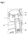
Figur 5 zeigt die Ansicht einer erfindungsgemäßen Anordnung mit einem an einem Getriebegehäuse eines Wischermotors angebrachten Druckausgleichselement,FIG. 5 shows the view of an arrangement according to the invention with a mounted on a gear housing of a wiper motor pressure compensation element, -
Figur 6 zeigt eine weitere Anordnung aus Getriebegehäuse und Druckausgleichselement.FIG. 6 shows a further arrangement of gear housing and pressure compensation element.
In
Der Adapter 2 ist mit dem unteren Ende seiner axialen Bohrung 5 auf das zu entlüftende Getriebegehäuse 10, insbesondere auf einen in die Bohrung 5 hineinragenden Entlüftungsdom (vgl.
Der Bauraumbedarf des asymmetrischen Adapters 2 - und damit auch der des Druckausgleichselementes - ist ersichtlich kleiner als bei einem symmetrischen Adapter mit beispielsweise vier am Umfang verteilten Vorsprüngen 12, vgl.
Wie in den
Bei der in
Das aus dem symmetrischen Adapter 2, einem luftdurchlässigen Filterelement - der Membran 14 - und dem Abdeckungselement 1 zusammengesetzte Druckausgleichselement wird auf den Entlüftungsdom 13 aufgesetzt. Der Entlüftungsdom 13 weist einen zum Getriebegehäuse 10 hin gelegenen Abschnitt 16 mit rundem Innenquerschnitt und zum Druckausgleichselement hin einen Abschnitt mit (recht)eckigem Innenquerschnitt 17 auf. Diese Formgebung bzw. deren Hintereinanderanordnung ist zur Vermeidung von Wasserbrücken durch inhomogene Oberflächenspannungen geeignet, so dass ein mögliches Eindringen von Wasser (insbesondere bei einem noch nicht durch ein Druckausgleichselement verschlossenen Entlüftungsdom 13) verhindert wird.The pressure compensation element composed of the
Der Adapter 2 besteht aus elastischem Werkstoff, so dass er mit seiner Bohrung 5 relativ leicht über den Dom 13 gestülpt bzw. aufgepresst werden kann. Auf der oberen Stirnseite des Adapters 2 ist als Filterelement eine poröse, luftdurchlässige und wasserundurchlässige Membrane 14 befestigt, wobei die Membrane durch in der Bohrung 5 des Adapters 2 kreuzförmig angebrachte Stege 9 gestützt ist. Dadurch wird eine Faltung der Membrane 14 verhindert. Die kreuzförmigen Stege 9 können, wie in
Im Übergangsbereich zwischen der Bodenfläche 3 des Abdeckungselementes 1 zu seiner Wandung ist mindestens eine Ausnehmung 18 vorgesehen, die in einem nicht dem Luftdurchlass 7 zwischen der Innenwand des Abdeckungselementes 1 und der Außenwand des Adapters 2 dienenden Segment des Abdeckungselementes 1 angeordnet ist. Gestautes Wasser in einem 'umgedrehten' Druckausgleichselement kann durch die Ausnehmung 18 abfließen.In the transition region between the
Typischerweise liegt das Druckausgleichselement - um die Entlüftung zu ermöglichen und um kein Wasser durch Kapillarwirkung anzuziehen - nicht völlig auf dem Gehäuse 10 auf. Selbst dann kann die Entlüftung und der Wasserabfluss dadurch gewährleistet werden, dass am freien Ende der Wandung 4 des Abdeckungselementes 1 mindestens eine Aussparung 20 vorgesehen ist, die jeweils im gleichen Segment wie die zugehörige Ausnehmung 18 angeordnet ist.Typically, the venting element is not fully supported on the
Die Membrane 14 - und der Luftkanal insgesamt - wird über das Abdeckungselement 1 geschützt. Dieses hat ein Labyrinthsystem, vgl.
Bei einer kostengünstigen Entlüftungsvariante ist die aus dem Getriebegehäuse 10 des Wischermotors austretende Abtriebswelle (vgl.
Claims (8)
- Pressure compensation element, which can be attached to a mounting orifice, in particular ventilation dome, of a housing, comprising:- a pot-shaped cover element (1) with a bottom face (3) and with a wall (4),- an adapter (2) which is inserted into the cover element (1) and is made from elastic material which has a continuous bore (5), of which the orifice directed towards the bottom face of the cover element is covered by a filter element (14),- an air passage (7) which is formed between the inner wall of the cover element (1) and the outer wall of the adapter (2) and also between the bottom face (3) of the cover element and the bore (5) of the adapter (2),- there being provided in the transitional region of the bottom face (3) to the wall (4) of the cover element (1) at least one recess (18) which is arranged in a segment of the circumference of the cover element (1), the said segment not serving for the passage of air (7) between the inner wall of the cover element (1) and the outer wall of the adapter (2).
- Pressure compensation element according to Claim 1, characterized in that a labyrinth system is provided in the interspace between the bottom face (3) of the cover element (1) and the filter element (14) and comprises in each case a wall element (19) facing the respective recess (18) and blocking direct access from the recess (18) to the centre of the interspace.
- Pressure compensation element according to Claim 2, characterized in that, at the free end of the wall (4) of the cover element (1), at least one clearance (20) is provided, which is arranged in each case in the same segment as the associated recess (18).
- Pressure compensation element according to one of Claims 1 to 3, characterized in that the filter element (14) is formed by a porous, air-permeable and water-repelling membrane (14), and in that the membrane (14) is supported by webs (9) mounted in the form of a cross in the bore (5) of the adapter (2).
- Motor vehicle electrical component, in particular gear housing (10) of a wiper motor, which comprises a pressure compensation element according to Claim 1, 2 or 4.
- Motor vehicle electrical component according to Claim 5, characterized in that the pressure compensation element is attached to a ventilation dome (13), the ventilation dome (13) having, towards the electrical component, a portion (16) with a round inner cross section and, towards the pressure compensation element, a portion with an angular inner cross section (17).
- Motor vehicle electrical component according to Claim 6, characterized in that the output shaft emerging from the gear housing (10) of the wiper motor is designed as a hollow shaft which serves for the pressure compensation of the wiper motor and to whose end projecting out of the gear housing (10) the pressure compensation element is attached.
- Motor vehicle electrical component according to Claim 7, characterized in that the pressure compensation element is attached to the mounting orifice by means of a press fit in the adapter bore (5), and in that the pressure compensation element is additionally designed with a latching hook (21) as a counterpiece to a latching nose (22) provided on the housing (10), the latching hook (21) bearing positively against the latching nose (22).
Applications Claiming Priority (3)
| Application Number | Priority Date | Filing Date | Title |
|---|---|---|---|
| DE102006061280 | 2006-12-22 | ||
| DE102007012703A DE102007012703A1 (en) | 2006-12-22 | 2007-03-16 | Pressure compensation element for a housing and motor vehicle electrical component with such a pressure compensation element |
| EP07821870A EP2127509B1 (en) | 2006-12-22 | 2007-10-26 | Pressure compensation element for a housing and electrical automotive component comprising said pressure compensation element |
Related Parent Applications (2)
| Application Number | Title | Priority Date | Filing Date |
|---|---|---|---|
| EP07821870A Division EP2127509B1 (en) | 2006-12-22 | 2007-10-26 | Pressure compensation element for a housing and electrical automotive component comprising said pressure compensation element |
| EP07821870.8 Division | 2007-10-26 |
Publications (2)
| Publication Number | Publication Date |
|---|---|
| EP2273860A1 EP2273860A1 (en) | 2011-01-12 |
| EP2273860B1 true EP2273860B1 (en) | 2012-09-19 |
Family
ID=39431921
Family Applications (2)
| Application Number | Title | Priority Date | Filing Date |
|---|---|---|---|
| EP07821870A Not-in-force EP2127509B1 (en) | 2006-12-22 | 2007-10-26 | Pressure compensation element for a housing and electrical automotive component comprising said pressure compensation element |
| EP10186637A Not-in-force EP2273860B1 (en) | 2006-12-22 | 2007-10-26 | Pressure compensation element for a housing and electrical automotive component comprising said pressure compensation element |
Family Applications Before (1)
| Application Number | Title | Priority Date | Filing Date |
|---|---|---|---|
| EP07821870A Not-in-force EP2127509B1 (en) | 2006-12-22 | 2007-10-26 | Pressure compensation element for a housing and electrical automotive component comprising said pressure compensation element |
Country Status (10)
| Country | Link |
|---|---|
| EP (2) | EP2127509B1 (en) |
| JP (1) | JP5065409B2 (en) |
| KR (1) | KR101381129B1 (en) |
| CN (1) | CN101584260B (en) |
| AT (1) | ATE502513T1 (en) |
| BR (1) | BRPI0720432A2 (en) |
| DE (2) | DE102007012703A1 (en) |
| PL (1) | PL2127509T3 (en) |
| RU (1) | RU2440903C2 (en) |
| WO (1) | WO2008077667A2 (en) |
Cited By (2)
| Publication number | Priority date | Publication date | Assignee | Title |
|---|---|---|---|---|
| US20120223446A1 (en) * | 2009-11-20 | 2012-09-06 | Neoperl Gmbh | Water-carrying line section having an aerating duct |
| EP3244714A1 (en) | 2016-05-13 | 2017-11-15 | Mahle International GmbH | Housing and regulating unit with housing |
Families Citing this family (31)
| Publication number | Priority date | Publication date | Assignee | Title |
|---|---|---|---|---|
| DE102008001591A1 (en) | 2008-05-06 | 2009-11-12 | Robert Bosch Gmbh | Housing for a drive device, drive device and method for checking the tightness of a pressure compensation membrane |
| US8430114B2 (en) * | 2009-09-08 | 2013-04-30 | GM Global Technology Operations LLC | Hydrophobic vent assembly |
| DE102010015610B4 (en) | 2010-04-19 | 2022-08-25 | Axel R. Hidde | Sealing ring with diaphragm valve |
| DE202010013887U1 (en) * | 2010-10-02 | 2012-01-10 | Hella Kgaa Hueck & Co. | Housing unit for mechanical, electromechanical and electrotechnical components |
| DE102011010640A1 (en) * | 2011-02-09 | 2012-08-09 | Emitec France S.A.S | Feed unit for conveying reducing agent |
| DE102011012630B4 (en) * | 2011-02-28 | 2015-03-19 | Sew-Eurodrive Gmbh & Co Kg | Compensation element, drive and method for producing a compensation element |
| CN102723801A (en) * | 2011-03-30 | 2012-10-10 | 比亚迪股份有限公司 | Internal and external pressure balance structure and motor comprising the same |
| CN103493611B (en) * | 2011-04-27 | 2016-03-16 | 皮尔伯格泵技术有限责任公司 | The housing unit for electric component used in a motor vehicle |
| DE102011112576A1 (en) | 2011-09-08 | 2013-03-14 | GM Global Technology Operations LLC (n. d. Gesetzen des Staates Delaware) | Pressure compensation element connected to vent pipe of device housing of motor vehicle component, gas reservoir chamber that is fluidly connected to environment by one-way valve whose forward direction is directed to environment |
| DE102012220368A1 (en) | 2012-11-08 | 2014-05-08 | Magna Powertrain Ag & Co. Kg | Drive unit for use in hybrid drive system for hybrid car, has oil-filled units arranged at front ends of rotor, and labyrinth seal arranged for air exchange and facilitating air exchange of oil-filled units opened in space |
| JP2014154408A (en) * | 2013-02-12 | 2014-08-25 | Stanley Electric Co Ltd | Vehicular lighting fixture |
| DE202013006741U1 (en) | 2013-07-26 | 2014-10-27 | GM Global Technology Operations, LLC (n.d. Ges. d. Staates Delaware) | Gearbox with hollow shaft |
| DE102013109260A1 (en) * | 2013-08-27 | 2015-03-05 | R.Stahl Schaltgeräte GmbH | Housing part for an explosion-proof housing with a porous body |
| DE102013111992B3 (en) * | 2013-10-30 | 2015-01-22 | Günther Spelsberg GmbH & Co. KG | Housing with ventilation element |
| DE102014206735A1 (en) | 2014-04-08 | 2015-10-08 | Continental Automotive Gmbh | Pressure compensation element for a housing |
| CN107148810B (en) | 2014-11-14 | 2019-11-01 | 三菱电机株式会社 | Waterproof ventilation part and electronic apparatus |
| US10687431B2 (en) * | 2015-02-18 | 2020-06-16 | Gvs S.P.A. | Element for improved ventilation of a housing containing an electrical, electronic, mechanical or similar device |
| DE102015209468A1 (en) * | 2015-05-22 | 2016-11-24 | Continental Teves Ag & Co. Ohg | Arrangement for the protection of electronics against interference radiation |
| DE102015218064B4 (en) * | 2015-09-21 | 2017-09-14 | Conti Temic Microelectronic Gmbh | transmission assembly |
| JP6542109B2 (en) * | 2015-11-20 | 2019-07-10 | 住友重機械工業株式会社 | Air breather |
| DE102016202965B3 (en) * | 2016-02-25 | 2017-08-31 | Audi Ag | Pressure equalization device for a housing, in particular a motor vehicle, and component for a motor vehicle |
| CN107041082A (en) * | 2016-11-18 | 2017-08-11 | 江门崇达电路技术有限公司 | The PCB process for pressing of dissymmetrical structure |
| JP6683170B2 (en) * | 2017-04-27 | 2020-04-15 | 株式会社アドヴィックス | Motor device |
| DE102018107678A1 (en) * | 2018-03-29 | 2019-10-02 | Automotive Lighting Reutlingen Gmbh | Micro-mirror having light module for a motor vehicle headlight |
| DE102018009382A1 (en) * | 2018-11-30 | 2020-06-04 | Dräger Safety AG & Co. KGaA | Fastening device for a sensor housing |
| DE102019103431B3 (en) * | 2019-02-12 | 2020-04-09 | Hugo Benzing Gmbh & Co. Kg | Pressure relief valve for relieving pressure generated in a cell-like cavity, such as a battery cell |
| DE102019114055A1 (en) * | 2019-05-27 | 2020-12-03 | Schaeffler Technologies AG & Co. KG | Pressure compensation element |
| DE202020005406U1 (en) | 2020-11-12 | 2022-02-21 | Konzelmann Gmbh | pressure equalization device |
| DE102020131994A1 (en) | 2020-11-17 | 2022-05-19 | Stego-Holding Gmbh | pressure compensation element |
| DE102021116815A1 (en) * | 2021-06-30 | 2023-01-05 | Marelli Automotive Lighting Reutlingen (Germany) GmbH | Ventilation module for a motor vehicle lighting device |
| WO2024002469A1 (en) * | 2022-06-28 | 2024-01-04 | Pierburg Gmbh | Blower |
Family Cites Families (8)
| Publication number | Priority date | Publication date | Assignee | Title |
|---|---|---|---|---|
| JPS59169472U (en) * | 1983-04-28 | 1984-11-13 | 日産自動車株式会社 | Breather structure of electrical components |
| DE3707050C2 (en) * | 1987-03-05 | 1995-09-28 | Bosch Gmbh Robert | Electrical switching device, in particular for motor vehicles |
| FR2631736B1 (en) * | 1988-05-20 | 1993-10-29 | Bosch Gmbh Robert | PRESSURE COMPENSATION ELEMENT FOR AN ELECTRICAL DISTRIBUTION APPARATUS |
| EP0377067A1 (en) * | 1989-01-05 | 1990-07-11 | W.L. Gore & Associates GmbH | Shut off device for a sealed housing |
| JP4043674B2 (en) * | 1999-11-18 | 2008-02-06 | 日東電工株式会社 | Ventilation cap and outdoor lamp, automobile lamp and automobile electrical parts using the same |
| JP2003008247A (en) * | 2001-06-19 | 2003-01-10 | Tdk Corp | Mounting structure for seal cap |
| WO2006031735A2 (en) * | 2004-09-13 | 2006-03-23 | Donaldson Company, Inc. | Breather filter |
| DE102006053113A1 (en) * | 2006-11-10 | 2008-05-15 | Robert Bosch Gmbh | Pressure compensation element for a housing |
-
2007
- 2007-03-16 DE DE102007012703A patent/DE102007012703A1/en not_active Withdrawn
- 2007-10-26 RU RU2009127859/11A patent/RU2440903C2/en not_active IP Right Cessation
- 2007-10-26 DE DE502007006749T patent/DE502007006749D1/en active Active
- 2007-10-26 EP EP07821870A patent/EP2127509B1/en not_active Not-in-force
- 2007-10-26 AT AT07821870T patent/ATE502513T1/en active
- 2007-10-26 EP EP10186637A patent/EP2273860B1/en not_active Not-in-force
- 2007-10-26 JP JP2009541933A patent/JP5065409B2/en not_active Expired - Fee Related
- 2007-10-26 PL PL07821870T patent/PL2127509T3/en unknown
- 2007-10-26 BR BRPI0720432-9A patent/BRPI0720432A2/en not_active IP Right Cessation
- 2007-10-26 WO PCT/EP2007/061507 patent/WO2008077667A2/en active Application Filing
- 2007-10-26 CN CN2007800477589A patent/CN101584260B/en not_active Expired - Fee Related
- 2007-10-26 KR KR1020097012946A patent/KR101381129B1/en not_active IP Right Cessation
Cited By (4)
| Publication number | Priority date | Publication date | Assignee | Title |
|---|---|---|---|---|
| US20120223446A1 (en) * | 2009-11-20 | 2012-09-06 | Neoperl Gmbh | Water-carrying line section having an aerating duct |
| US9238906B2 (en) * | 2009-11-20 | 2016-01-19 | Neoperl Gmbh | Water-carrying line section having an aerating duct |
| EP3244714A1 (en) | 2016-05-13 | 2017-11-15 | Mahle International GmbH | Housing and regulating unit with housing |
| DE102016208276A1 (en) * | 2016-05-13 | 2017-11-16 | Mahle International Gmbh | setting device |
Also Published As
| Publication number | Publication date |
|---|---|
| BRPI0720432A2 (en) | 2014-01-07 |
| DE102007012703A1 (en) | 2008-06-26 |
| KR20090094100A (en) | 2009-09-03 |
| KR101381129B1 (en) | 2014-04-04 |
| RU2440903C2 (en) | 2012-01-27 |
| EP2127509A2 (en) | 2009-12-02 |
| JP2010513813A (en) | 2010-04-30 |
| JP5065409B2 (en) | 2012-10-31 |
| ATE502513T1 (en) | 2011-04-15 |
| PL2127509T3 (en) | 2011-08-31 |
| DE502007006749D1 (en) | 2011-04-28 |
| WO2008077667A2 (en) | 2008-07-03 |
| EP2273860A1 (en) | 2011-01-12 |
| RU2009127859A (en) | 2011-01-27 |
| CN101584260A (en) | 2009-11-18 |
| EP2127509B1 (en) | 2011-03-16 |
| CN101584260B (en) | 2012-01-25 |
| WO2008077667A3 (en) | 2009-04-16 |
Similar Documents
| Publication | Publication Date | Title |
|---|---|---|
| EP2273860B1 (en) | Pressure compensation element for a housing and electrical automotive component comprising said pressure compensation element | |
| DE4426028C1 (en) | Butterfly valve for I.C. engine exhaust line | |
| DE4421403C2 (en) | Ball joint | |
| WO2000071978A1 (en) | Sensor module with a housing that can be mounted on a wall | |
| WO2005108835A1 (en) | Valve arrangement mounted in a crankcase ventilator | |
| DE3105302A1 (en) | Venting device | |
| WO2006029614A1 (en) | Sealing bush, hydraulic unit, and check valve | |
| DE102009024317A1 (en) | Valve arrangement for an internal combustion engine | |
| DE102008001594B4 (en) | Carrier with a pressure-equalizing membrane and drive device, in particular for motor vehicle applications | |
| DE102006046488B4 (en) | Sealed electrical connection of a housing of an electrical control unit and hydraulic machine with a housing having such a connection | |
| DE19846084A1 (en) | Ball valve | |
| DE102006038740A1 (en) | Shifting dome for manual gearbox in motor vehicle, has rear section formed by separate component and attached to dome in area of breather hole, where separate component is formed as ring | |
| DE4304775C2 (en) | Spherical bearings | |
| DE202004012604U1 (en) | ball joint | |
| EP1718504A1 (en) | Arrangement for fixing a gas generator of an air bag unit | |
| DE102011085377B3 (en) | Vent cap for use in switching dome, has vent channel that is located in casing, which is extended through vent opening to exterior of base | |
| EP2800117B1 (en) | Actuating unit | |
| DE102005048396A1 (en) | sensor assembly | |
| DE102012107023B3 (en) | Protective cover for a steering spindle | |
| DE19948422A1 (en) | Selector unit especially for gearbox in motor vehicle has cover fabricated in one piece from sheet metal in forming process and with stop contour which interacts with stop element on transmission shaft | |
| DE19606002C2 (en) | Tensioning or sliding rail for chain drives of internal combustion engines | |
| EP2125453B1 (en) | Housing arrangement of a windshield wiper assembly of a motor vehicle | |
| DE102004012229A1 (en) | Electronic device, has partition wall that is sectionally moved such that pressure compensation occurs between space section and pressure compensation space section, and electronic components arranged in internal space of casing | |
| DE102007023121B4 (en) | Valve for insertion into a housing, in particular an internal combustion engine | |
| DE102006014477B4 (en) | Connection system with drainage groove |
Legal Events
| Date | Code | Title | Description |
|---|---|---|---|
| PUAI | Public reference made under article 153(3) epc to a published international application that has entered the european phase |
Free format text: ORIGINAL CODE: 0009012 |
|
| AC | Divisional application: reference to earlier application |
Ref document number: 2127509 Country of ref document: EP Kind code of ref document: P |
|
| AK | Designated contracting states |
Kind code of ref document: A1 Designated state(s): AT BE BG CH CY CZ DE DK EE ES FI FR GB GR HU IE IS IT LI LT LU LV MC MT NL PL PT RO SE SI SK TR |
|
| 17P | Request for examination filed |
Effective date: 20110712 |
|
| GRAP | Despatch of communication of intention to grant a patent |
Free format text: ORIGINAL CODE: EPIDOSNIGR1 |
|
| RIC1 | Information provided on ipc code assigned before grant |
Ipc: H02K 5/10 20060101ALI20120523BHEP Ipc: H05K 5/02 20060101ALI20120523BHEP Ipc: F16H 57/027 20120101ALI20120523BHEP Ipc: H05K 5/06 20060101AFI20120523BHEP Ipc: F16K 24/04 20060101ALI20120523BHEP Ipc: F21V 31/03 20060101ALI20120523BHEP |
|
| GRAS | Grant fee paid |
Free format text: ORIGINAL CODE: EPIDOSNIGR3 |
|
| GRAA | (expected) grant |
Free format text: ORIGINAL CODE: 0009210 |
|
| AC | Divisional application: reference to earlier application |
Ref document number: 2127509 Country of ref document: EP Kind code of ref document: P |
|
| AK | Designated contracting states |
Kind code of ref document: B1 Designated state(s): AT BE BG CH CY CZ DE DK EE ES FI FR GB GR HU IE IS IT LI LT LU LV MC MT NL PL PT RO SE SI SK TR |
|
| REG | Reference to a national code |
Ref country code: GB Ref legal event code: FG4D Free format text: NOT ENGLISH |
|
| REG | Reference to a national code |
Ref country code: CH Ref legal event code: EP |
|
| REG | Reference to a national code |
Ref country code: IE Ref legal event code: FG4D Free format text: LANGUAGE OF EP DOCUMENT: GERMAN |
|
| REG | Reference to a national code |
Ref country code: AT Ref legal event code: REF Ref document number: 576554 Country of ref document: AT Kind code of ref document: T Effective date: 20121015 |
|
| REG | Reference to a national code |
Ref country code: DE Ref legal event code: R096 Ref document number: 502007010582 Country of ref document: DE Effective date: 20121108 |
|
| PG25 | Lapsed in a contracting state [announced via postgrant information from national office to epo] |
Ref country code: FI Free format text: LAPSE BECAUSE OF FAILURE TO SUBMIT A TRANSLATION OF THE DESCRIPTION OR TO PAY THE FEE WITHIN THE PRESCRIBED TIME-LIMIT Effective date: 20120919 Ref country code: LT Free format text: LAPSE BECAUSE OF FAILURE TO SUBMIT A TRANSLATION OF THE DESCRIPTION OR TO PAY THE FEE WITHIN THE PRESCRIBED TIME-LIMIT Effective date: 20120919 |
|
| REG | Reference to a national code |
Ref country code: NL Ref legal event code: VDEP Effective date: 20120919 |
|
| REG | Reference to a national code |
Ref country code: LT Ref legal event code: MG4D Effective date: 20120905 |
|
| PG25 | Lapsed in a contracting state [announced via postgrant information from national office to epo] |
Ref country code: LV Free format text: LAPSE BECAUSE OF FAILURE TO SUBMIT A TRANSLATION OF THE DESCRIPTION OR TO PAY THE FEE WITHIN THE PRESCRIBED TIME-LIMIT Effective date: 20120919 Ref country code: SI Free format text: LAPSE BECAUSE OF FAILURE TO SUBMIT A TRANSLATION OF THE DESCRIPTION OR TO PAY THE FEE WITHIN THE PRESCRIBED TIME-LIMIT Effective date: 20120919 Ref country code: SE Free format text: LAPSE BECAUSE OF FAILURE TO SUBMIT A TRANSLATION OF THE DESCRIPTION OR TO PAY THE FEE WITHIN THE PRESCRIBED TIME-LIMIT Effective date: 20120919 Ref country code: GR Free format text: LAPSE BECAUSE OF FAILURE TO SUBMIT A TRANSLATION OF THE DESCRIPTION OR TO PAY THE FEE WITHIN THE PRESCRIBED TIME-LIMIT Effective date: 20121220 |
|
| BERE | Be: lapsed |
Owner name: ROBERT BOSCH G.M.B.H. Effective date: 20121031 |
|
| PG25 | Lapsed in a contracting state [announced via postgrant information from national office to epo] |
Ref country code: EE Free format text: LAPSE BECAUSE OF FAILURE TO SUBMIT A TRANSLATION OF THE DESCRIPTION OR TO PAY THE FEE WITHIN THE PRESCRIBED TIME-LIMIT Effective date: 20120919 Ref country code: NL Free format text: LAPSE BECAUSE OF FAILURE TO SUBMIT A TRANSLATION OF THE DESCRIPTION OR TO PAY THE FEE WITHIN THE PRESCRIBED TIME-LIMIT Effective date: 20120919 Ref country code: IS Free format text: LAPSE BECAUSE OF FAILURE TO SUBMIT A TRANSLATION OF THE DESCRIPTION OR TO PAY THE FEE WITHIN THE PRESCRIBED TIME-LIMIT Effective date: 20130119 Ref country code: RO Free format text: LAPSE BECAUSE OF FAILURE TO SUBMIT A TRANSLATION OF THE DESCRIPTION OR TO PAY THE FEE WITHIN THE PRESCRIBED TIME-LIMIT Effective date: 20120919 Ref country code: ES Free format text: LAPSE BECAUSE OF FAILURE TO SUBMIT A TRANSLATION OF THE DESCRIPTION OR TO PAY THE FEE WITHIN THE PRESCRIBED TIME-LIMIT Effective date: 20121230 Ref country code: CZ Free format text: LAPSE BECAUSE OF FAILURE TO SUBMIT A TRANSLATION OF THE DESCRIPTION OR TO PAY THE FEE WITHIN THE PRESCRIBED TIME-LIMIT Effective date: 20120919 |
|
| PG25 | Lapsed in a contracting state [announced via postgrant information from national office to epo] |
Ref country code: PT Free format text: LAPSE BECAUSE OF FAILURE TO SUBMIT A TRANSLATION OF THE DESCRIPTION OR TO PAY THE FEE WITHIN THE PRESCRIBED TIME-LIMIT Effective date: 20130121 Ref country code: PL Free format text: LAPSE BECAUSE OF FAILURE TO SUBMIT A TRANSLATION OF THE DESCRIPTION OR TO PAY THE FEE WITHIN THE PRESCRIBED TIME-LIMIT Effective date: 20120919 Ref country code: SK Free format text: LAPSE BECAUSE OF FAILURE TO SUBMIT A TRANSLATION OF THE DESCRIPTION OR TO PAY THE FEE WITHIN THE PRESCRIBED TIME-LIMIT Effective date: 20120919 Ref country code: MC Free format text: LAPSE BECAUSE OF NON-PAYMENT OF DUE FEES Effective date: 20121031 |
|
| REG | Reference to a national code |
Ref country code: CH Ref legal event code: PL |
|
| REG | Reference to a national code |
Ref country code: IE Ref legal event code: MM4A |
|
| PLBE | No opposition filed within time limit |
Free format text: ORIGINAL CODE: 0009261 |
|
| REG | Reference to a national code |
Ref country code: FR Ref legal event code: ST Effective date: 20130628 |
|
| STAA | Information on the status of an ep patent application or granted ep patent |
Free format text: STATUS: NO OPPOSITION FILED WITHIN TIME LIMIT |
|
| PG25 | Lapsed in a contracting state [announced via postgrant information from national office to epo] |
Ref country code: BE Free format text: LAPSE BECAUSE OF NON-PAYMENT OF DUE FEES Effective date: 20121031 Ref country code: BG Free format text: LAPSE BECAUSE OF FAILURE TO SUBMIT A TRANSLATION OF THE DESCRIPTION OR TO PAY THE FEE WITHIN THE PRESCRIBED TIME-LIMIT Effective date: 20121219 Ref country code: IE Free format text: LAPSE BECAUSE OF NON-PAYMENT OF DUE FEES Effective date: 20121026 Ref country code: DK Free format text: LAPSE BECAUSE OF FAILURE TO SUBMIT A TRANSLATION OF THE DESCRIPTION OR TO PAY THE FEE WITHIN THE PRESCRIBED TIME-LIMIT Effective date: 20120919 Ref country code: CH Free format text: LAPSE BECAUSE OF NON-PAYMENT OF DUE FEES Effective date: 20121031 Ref country code: LI Free format text: LAPSE BECAUSE OF NON-PAYMENT OF DUE FEES Effective date: 20121031 |
|
| 26N | No opposition filed |
Effective date: 20130620 |
|
| GBPC | Gb: european patent ceased through non-payment of renewal fee |
Effective date: 20121219 |
|
| PG25 | Lapsed in a contracting state [announced via postgrant information from national office to epo] |
Ref country code: FR Free format text: LAPSE BECAUSE OF NON-PAYMENT OF DUE FEES Effective date: 20121119 Ref country code: IT Free format text: LAPSE BECAUSE OF FAILURE TO SUBMIT A TRANSLATION OF THE DESCRIPTION OR TO PAY THE FEE WITHIN THE PRESCRIBED TIME-LIMIT Effective date: 20120919 |
|
| REG | Reference to a national code |
Ref country code: DE Ref legal event code: R097 Ref document number: 502007010582 Country of ref document: DE Effective date: 20130620 |
|
| PG25 | Lapsed in a contracting state [announced via postgrant information from national office to epo] |
Ref country code: MT Free format text: LAPSE BECAUSE OF FAILURE TO SUBMIT A TRANSLATION OF THE DESCRIPTION OR TO PAY THE FEE WITHIN THE PRESCRIBED TIME-LIMIT Effective date: 20120919 Ref country code: CY Free format text: LAPSE BECAUSE OF FAILURE TO SUBMIT A TRANSLATION OF THE DESCRIPTION OR TO PAY THE FEE WITHIN THE PRESCRIBED TIME-LIMIT Effective date: 20120919 Ref country code: GB Free format text: LAPSE BECAUSE OF NON-PAYMENT OF DUE FEES Effective date: 20121219 |
|
| REG | Reference to a national code |
Ref country code: AT Ref legal event code: MM01 Ref document number: 576554 Country of ref document: AT Kind code of ref document: T Effective date: 20121031 |
|
| PG25 | Lapsed in a contracting state [announced via postgrant information from national office to epo] |
Ref country code: AT Free format text: LAPSE BECAUSE OF NON-PAYMENT OF DUE FEES Effective date: 20121031 |
|
| PG25 | Lapsed in a contracting state [announced via postgrant information from national office to epo] |
Ref country code: TR Free format text: LAPSE BECAUSE OF FAILURE TO SUBMIT A TRANSLATION OF THE DESCRIPTION OR TO PAY THE FEE WITHIN THE PRESCRIBED TIME-LIMIT Effective date: 20120919 |
|
| PG25 | Lapsed in a contracting state [announced via postgrant information from national office to epo] |
Ref country code: LU Free format text: LAPSE BECAUSE OF NON-PAYMENT OF DUE FEES Effective date: 20121026 |
|
| PG25 | Lapsed in a contracting state [announced via postgrant information from national office to epo] |
Ref country code: HU Free format text: LAPSE BECAUSE OF FAILURE TO SUBMIT A TRANSLATION OF THE DESCRIPTION OR TO PAY THE FEE WITHIN THE PRESCRIBED TIME-LIMIT Effective date: 20071026 |
|
| PGFP | Annual fee paid to national office [announced via postgrant information from national office to epo] |
Ref country code: DE Payment date: 20171206 Year of fee payment: 11 |
|
| REG | Reference to a national code |
Ref country code: DE Ref legal event code: R119 Ref document number: 502007010582 Country of ref document: DE |
|
| PG25 | Lapsed in a contracting state [announced via postgrant information from national office to epo] |
Ref country code: DE Free format text: LAPSE BECAUSE OF NON-PAYMENT OF DUE FEES Effective date: 20190501 |