JP5064509B2 - Ladle flow control system and assembly method thereof - Google Patents
Ladle flow control system and assembly method thereof Download PDFInfo
- Publication number
- JP5064509B2 JP5064509B2 JP2009533641A JP2009533641A JP5064509B2 JP 5064509 B2 JP5064509 B2 JP 5064509B2 JP 2009533641 A JP2009533641 A JP 2009533641A JP 2009533641 A JP2009533641 A JP 2009533641A JP 5064509 B2 JP5064509 B2 JP 5064509B2
- Authority
- JP
- Japan
- Prior art keywords
- carrier frame
- housing
- control system
- slider
- ladle
- Prior art date
- Legal status (The legal status is an assumption and is not a legal conclusion. Google has not performed a legal analysis and makes no representation as to the accuracy of the status listed.)
- Expired - Fee Related
Links
Images


Classifications
-
- B—PERFORMING OPERATIONS; TRANSPORTING
- B22—CASTING; POWDER METALLURGY
- B22D—CASTING OF METALS; CASTING OF OTHER SUBSTANCES BY THE SAME PROCESSES OR DEVICES
- B22D41/00—Casting melt-holding vessels, e.g. ladles, tundishes, cups or the like
- B22D41/14—Closures
- B22D41/22—Closures sliding-gate type, i.e. having a fixed plate and a movable plate in sliding contact with each other for selective registry of their openings
- B22D41/28—Plates therefor
- B22D41/34—Supporting, fixing or centering means therefor
-
- B—PERFORMING OPERATIONS; TRANSPORTING
- B22—CASTING; POWDER METALLURGY
- B22D—CASTING OF METALS; CASTING OF OTHER SUBSTANCES BY THE SAME PROCESSES OR DEVICES
- B22D41/00—Casting melt-holding vessels, e.g. ladles, tundishes, cups or the like
- B22D41/14—Closures
- B22D41/22—Closures sliding-gate type, i.e. having a fixed plate and a movable plate in sliding contact with each other for selective registry of their openings
- B22D41/24—Closures sliding-gate type, i.e. having a fixed plate and a movable plate in sliding contact with each other for selective registry of their openings characterised by a rectilinearly movable plate
-
- B—PERFORMING OPERATIONS; TRANSPORTING
- B22—CASTING; POWDER METALLURGY
- B22D—CASTING OF METALS; CASTING OF OTHER SUBSTANCES BY THE SAME PROCESSES OR DEVICES
- B22D41/00—Casting melt-holding vessels, e.g. ladles, tundishes, cups or the like
- B22D41/14—Closures
- B22D41/22—Closures sliding-gate type, i.e. having a fixed plate and a movable plate in sliding contact with each other for selective registry of their openings
- B22D41/38—Means for operating the sliding gate
Description
本発明は、取鍋(ladle)の溶鋼出口においてベース板の外面上に設置された取鍋流量制御システム及びその組み立て方法に関し、機械製造分野に属する。 The present invention relates to a ladle flow rate control system installed on the outer surface of a base plate at a molten steel outlet of a ladle and a method for assembling the ladle flow rate control system, and belongs to the machine manufacturing field.
スライダーとキャリア枠との間の動き方と、スライド板界面圧を生成する方法とに関して、従来の取鍋流量制御システムには、主に2種類の装置がある。一つ目の装置の動き方としては、取鍋スライディングノズルの開閉を実現するのに使用される、レール間の相対的な動きがあり、スライド板界面圧を生成する方法は、手動による押し付けである。二つ目の装置の動き方としては、取鍋スライディングノズルの開閉を実現するのに使用される、レール車輪とレールとの相対的な動きがあり、スライド板界面圧を生成する方法は、自動的押し付けである。一つ目の装置の動作においては、レール間の面接触は高い安全性を有しているが、自動的にスライド板界面圧を生成することはなく、複雑な操作と高い労働集約度を必要とする場合がある。二つ目の装置のスライド板界面圧を生成する方法では、当該装置がレール上でレール車輪を引っ張る。この時、機構のスライド板上の界面圧は、自動的に生成される。しかし、その動作において、レール車輪とレールは相対的な動きをする必要があり、その結果、レール車輪とレールとの間の接触は線接触となる。機構全体の圧力は、その接触線を介して伝達され、ローラーとレールとに重大な摩耗を引き起こす。このような動作は、レール車輪とレールとに対して相対的に高い要求であり、機構全体の安全な動作に影響する。同時に、弾性体を押し下げる力が、スライダーのレール車輪がキャリア枠上のレールに接触した後、生成される。全体の動作において、スライド板界面圧の伝達箇所は、スライダーの移動とともに変化する。従って、スライド板界面圧は安定していない。また、上記2種類の装置の底板とスライド板との固定機構の構造が合理的でないために、これらの固定機構の耐用年数は短く、複雑な操作と高い労働集約度を必要とする。 There are mainly two types of conventional ladle flow rate control systems with respect to the way of movement between the slider and the carrier frame and the method of generating the slide plate interface pressure. One way to move the device is the relative movement between the rails used to open and close the ladle sliding nozzle. is there. The second method of movement is the relative movement between the rail wheel and the rail used to open and close the ladle sliding nozzle, and the method of generating the sliding plate interface pressure is automatic. It is a manual push. In the operation of the first device, the surface contact between the rails is highly safe, but it does not automatically generate the slide plate interface pressure, requiring complicated operation and high labor intensity. It may be. In the method of generating the slide plate interface pressure of the second device, the device pulls the rail wheel on the rail. At this time, the interfacial pressure on the slide plate of the mechanism is automatically generated. However, in that operation, the rail wheel and the rail need to move relative to each other, so that the contact between the rail wheel and the rail is a line contact. The pressure of the entire mechanism is transmitted through its contact lines, causing significant wear on the rollers and rails. Such an operation is a relatively high demand for the rail wheel and the rail, and affects the safe operation of the entire mechanism. At the same time, a force that pushes down the elastic body is generated after the rail wheel of the slider contacts the rail on the carrier frame. In the entire operation, the transmission position of the slide plate interface pressure changes as the slider moves. Therefore, the slide plate interface pressure is not stable. In addition, since the structure of the fixing mechanism between the bottom plate and the slide plate of the above two types of devices is not rational, the service life of these fixing mechanisms is short, requiring complicated operation and high labor intensity.
本発明の第1の技術的目的は、従来の前記欠点を克服する取鍋流量制御システムを提供することである。この装置は、レール間の相対的な動きを採用し、面接触により取鍋スライディングノズルの開閉を制御し、キャリア枠上のローリング機構とハウジング上の案内レールとを用いて自動押し付けを実現する。スライダーとキャリア枠の間の相対的な移動において、スライド板界面圧の変動は明らかに削減され、システムの全体的な安定性が向上する。
The first technical object of the present invention is to provide a ladle flow control system that overcomes the above-mentioned drawbacks of the prior art. This device adopts relative movement between rails, controls the opening and closing of the ladle sliding nozzle by surface contact, and realizes automatic pressing using a rolling mechanism on the carrier frame and a guide rail on the housing. In the relative movement between the slider and the carrier frame, the variation of the slide plate interface pressure is obviously reduced and the overall stability of the system is improved.
本発明の第2の技術的目的は、従来の前記欠点を克服する取鍋流量制御システムを提供することである。底板とスライド板とに対して、合理的な構造と簡単な操作と高い安全性と信頼性とを特徴とする押し出し器を設ける。 The second technical object of the present invention is to provide a ladle flow control system that overcomes the above-mentioned drawbacks of the prior art. The bottom plate and the slide plate are provided with an extruder characterized by a reasonable structure, simple operation, high safety and reliability.
本発明の第3の技術的目的は、従来の前記欠点を克服する取鍋流量制御システムの組み立て方法を提供することである。この装置の設置及び分解において、本方法は弾性体の圧縮と解放とを実現し、スライド板界面圧の生成と解除の動的なプロセスを形成する。キャリア枠上のレール車輪をハウジングのレールに対してスライドさせることにより、弾性体を押し下げる力が生成される。圧力が生成された後、スライダーの移動に伴う圧力変動がないため、圧力の安定性が明らかに向上する。また、底板とスライド板のための固定機構は、合理的な構造と簡便で実用的な操作と高い安全性と信頼性とを特徴とする。 The third technical object of the present invention is to provide a method for assembling a ladle flow control system that overcomes the above-mentioned drawbacks of the prior art. In the installation and disassembly of this device, the method realizes compression and release of the elastic body and forms a dynamic process of generating and releasing the slide plate interface pressure. By sliding the rail wheel on the carrier frame with respect to the rail of the housing, a force for pushing down the elastic body is generated. After the pressure is generated, there is no pressure fluctuation associated with the movement of the slider, so the pressure stability is clearly improved. Also, the fixing mechanism for the bottom plate and the slide plate is characterized by a reasonable structure, simple and practical operation, high safety and reliability.
本発明の上記技術的目的は、次の解決手段によって達成される。 The above technical object of the present invention is achieved by the following means.
取鍋に固定されたベース板と、該ベース板に固定されたハウジングであって、その上部にスライディングノズルの駆動機構が接続される該ハウジングと、該ハウジング上に設けられたキャリア枠であって、圧力を生成するための弾性体が該キャリア枠上に設けられた該キャリア枠と、該キャリア枠上に設けられたスライダーと、該ハウジングの表面と、該スライダーの表面とにそれぞれ設けられたノッチと、対応する該ノッチにそれぞれ受容される底板とスライド板とを備える取鍋流量制御システムである。長い溝が該ハウジングに設けられ、該長い溝の一端には、内壁に沿って、ブロッキング部が該キャリア枠側に設けられ、該キャリア枠上に、ローリング機構が、該長い溝に対応して設けられ、該ローリング機構は、該長い溝に受容され、該ブロッキング部の内面に案内レールが設けられ、該キャリア枠上の該ローリング機構が、該長い溝の内側に向かって該案内レールに沿って移動し、該ブロッキング部において方向決めされる。 A base plate fixed to the ladle, a housing fixed to the base plate, the housing to which a sliding nozzle driving mechanism is connected, and a carrier frame provided on the housing An elastic body for generating pressure is provided on each of the carrier frame provided on the carrier frame, a slider provided on the carrier frame, a surface of the housing, and a surface of the slider. A ladle flow control system comprising a notch, a bottom plate and a slide plate respectively received in the corresponding notch. A long groove is provided in the housing, and at one end of the long groove, a blocking portion is provided on the carrier frame side along the inner wall, and a rolling mechanism is provided on the carrier frame corresponding to the long groove. The rolling mechanism is received in the long groove, and a guide rail is provided on the inner surface of the blocking portion, and the rolling mechanism on the carrier frame extends along the guide rail toward the inside of the long groove. And the direction is determined in the blocking portion.
相互に結合されるレールが前記キャリア枠と前記スライダーとに対応して設けられる。さらに、該キャリア枠と該スライダーは、それぞれ設けられた該レール間の面接触を介して相対移動する。該ローリング機構が該長い溝に入るのを容易にするために、前記案内レールが、前記ローリング機構の移動の方向に沿って傾斜した面を形成し、前記傾斜した面と水平面との間の角度の範囲は、15度〜45度である。前記ブロッキング部は、前記長い溝の一端における、前記内壁に沿って設けられた、前記キャリア枠に向かって延出する側壁でもよく、延出した該側壁の上部を相対的な曲折させることによって形成されてもよい。前記ローリング機構は、前記キャリア枠上に対称に設けられたローラーから構成されてもよい。空間構造に対する異なる要求に対応して、前記ローラーは、完全軸ローラー(holoaxial rollers)又は半軸ローラー(half-axle rollers)であってよい。スライド板を該スライダーのノッチに、底板を該ハウジングのノッチに固定する時の便宜上、押し出し器が、前記スライダーの前記ノッチの一端と、前記ハウジングの前記ノッチの一端にそれぞれ設けられる。前記押し出し器は、支持枠を備え、該支持枠は上部キャリア枠と下部台枠とから成る。上部カバー板と下部カバー板とが、該上部キャリア枠の両面にそれぞれ固定されて、遠心輪を該キャリア枠内に心棒を介して固定する。該下部台枠の両端にそれぞれ押し出しポールが結合され、該押し出しポールの形状と位置は、前記底板と前記スライド板との縁の形状に対応している。 Rails coupled to each other are provided corresponding to the carrier frame and the slider. Further, the carrier frame and the slider move relative to each other through surface contact between the rails provided. In order to facilitate the rolling mechanism entering the long groove, the guide rail forms an inclined surface along the direction of movement of the rolling mechanism, and an angle between the inclined surface and a horizontal plane. The range of 15 degrees to 45 degrees. The blocking part may be a side wall provided along the inner wall at one end of the long groove and extending toward the carrier frame, and is formed by relatively bending the upper part of the extended side wall. May be. The rolling mechanism may be composed of rollers provided symmetrically on the carrier frame. Corresponding to the different demands on the spatial structure, the roller may be a full-axis roller or a half-axle roller. For convenience when the slide plate is fixed to the notch of the slider and the bottom plate is fixed to the notch of the housing, pushers are respectively provided at one end of the notch of the slider and one end of the notch of the housing. The extruder includes a support frame, and the support frame includes an upper carrier frame and a lower base frame. An upper cover plate and a lower cover plate are respectively fixed to both surfaces of the upper carrier frame, and the centrifugal wheel is fixed in the carrier frame via a mandrel. Extrusion poles are coupled to both ends of the lower underframe, respectively, and the shape and position of the extrusion poles correspond to the shape of the edge between the bottom plate and the slide plate.
取鍋流量制御システムの組み立て方法であって、
ステップ1:ハウジングを取鍋ベース板に固定し、キャリア枠の片側を該ハウジングの片側にピボットを介して結合し、スライダーをキャリア枠上に設置し、ウェルブロックとノズルを固定し、スライディングノズルの駆動機構を該ハウジングの上面に接続し、底板とスライド板とを該ハウジングと該スライダーとにそれぞれ固定し、該ハウジングに冠着するように該キャリア枠を回転させて、該キャリア枠のローリング機構を該ハウジングの長い溝に受容させるステップと、
ステップ2:該スライディングノズルの該駆動機構が、該キャリア枠と該スライダーとを一緒に駆動し、それにより該キャリア枠の該ローリング機構が、該長い溝内を案内レールに沿って移動し、ブロッキング部において方向決めされ、この時、該キャリア枠上に設けられ、該ローリング機構に接続された弾性体が、圧力により変形し締止力(pretightening force)を発生させ、該キャリア枠が該ハウジング上で方向決めされ、これにより該駆動機構が該スライダーを単独に駆動して該キャリア枠上で往復運動させ、該取鍋スライディングノズルの開閉を制御することを可能にするステップとを備える組み立て方法である。
A ladle flow control system assembly method,
Step 1: The housing is fixed to the pan base plate, one side of the carrier frame is connected to one side of the housing via a pivot, a slider is installed on the carrier frame, the well block and the nozzle are fixed, and the sliding nozzle A driving mechanism is connected to the upper surface of the housing, a bottom plate and a slide plate are fixed to the housing and the slider, respectively, and the carrier frame is rotated so as to be crowned on the housing. Receiving in a long groove in the housing;
Step 2: The drive mechanism of the sliding nozzle drives the carrier frame and the slider together so that the rolling mechanism of the carrier frame moves along the guide rail in the long groove and blocks At this time, an elastic body provided on the carrier frame and connected to the rolling mechanism is deformed by pressure to generate a pretightening force, and the carrier frame is mounted on the housing. An assembly method comprising the steps of: allowing the drive mechanism to independently drive the slider to reciprocate on the carrier frame to control the opening and closing of the ladle sliding nozzle. is there.
まとめると、本発明の取鍋流量制御システムは、レール間の相対的な動きを採用して、面接触により取鍋スライディングノズルの開閉を制御し、キャリア枠上のローリング機構とハウジング上の案内レールとによって自動的押し付けを実現する。スライダーとキャリア枠の間の相対的な移動において、スライド板界面圧の変動は明らかに削減され、システムの全体的な安定性が向上する。この取鍋流量制御システムは、底板とスライド板とのための押し出し器が設けられ、合理的な構造と簡便で実用的な操作と高い安全性と信頼性とを特徴とする。 In summary, the ladle flow control system of the present invention adopts relative movement between the rails to control the opening and closing of the ladle sliding nozzle by surface contact, and the rolling mechanism on the carrier frame and the guide rail on the housing. With this, automatic pressing is realized. In the relative movement between the slider and the carrier frame, the variation of the slide plate interface pressure is obviously reduced and the overall stability of the system is improved. This ladle flow rate control system is provided with an extruder for the bottom plate and slide plate, and is characterized by a reasonable structure, simple and practical operation, and high safety and reliability.
この装置の設置及び分解において、本発明の取鍋流量制御システムの組み立て方法は、弾性体の圧縮と解放とを実現し、スライド板界面圧の生成と解除の動的なプロセスを形成する。弾性体を押し下げる力が、キャリア枠のレール車輪をハウジングのレールに対してスライドさせることにより、生成される。圧力が生成された後、スライダーの移動に伴う圧力変動がなく、スライド板界面圧の安定性が明らかに向上する。また、底板とスライド板とのための固定機構は、合理的な構造と簡便で実用的な操作と高い安全性と信頼性とを特徴とする。 In the installation and disassembly of this apparatus, the ladle flow control system assembly method of the present invention realizes compression and release of the elastic body and forms a dynamic process of generating and releasing the slide plate interface pressure. A force for pushing down the elastic body is generated by sliding the rail wheel of the carrier frame with respect to the rail of the housing. After the pressure is generated, there is no pressure fluctuation accompanying the movement of the slider, and the stability of the slide plate interface pressure is clearly improved. Also, the fixing mechanism for the bottom plate and the slide plate is characterized by a reasonable structure, simple and practical operation, high safety and reliability.
本発明の技術的提案を添付図と実施形態とを用いて下記に詳細に説明する。 The technical proposal of the present invention will be described in detail below with reference to the accompanying drawings and embodiments.
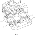
図1は本発明の全体構造図である。図1から分かるように、本発明は、取鍋流量制御システムを提供するものであり、該システムは、取鍋に固定されたベース板100と、該ベース板100に固定されたハウジング1であって、その上部にスライディングノズルの駆動機構2が接続される該ハウジング1と、該ハウジング1上に設けられたキャリア枠3であって、圧力を生成するための弾性体4が該キャリア枠3上に設けられた該キャリア枠3と、該キャリア枠3上に設けられたスライダー5と、該ハウジング1の表面と、該スライダー5の表面とにそれぞれ設けられたノッチ11及び51(当該図においては不図示)と、対応する該ノッチ11及び51にそれぞれ受容される底板111とスライド板511とを備える。図2は本発明のハウジングの構造図である。図1と図2を組み合わせて分かるように、長い溝12がハウジング1に設けられ、ブロッキング部13が長い溝12の一端に設けられ、内壁に沿ってキャリア枠3に向かって延びている。図3は本発明のキャリア枠の構造図である。図1〜図3から分かるように、キャリア枠3上に、ローリング機構31が、長い溝12に対応して設けられている。ローリング機構31は、長い溝12に受容される。ブロッキング部13の内面に案内レール14が設けられ、キャリア枠3のローリング機構31が長い溝12の内側に向かって案内レール14に沿って移動し、ブロッキング部13において方向決めされる。ローリング機構31がブロッキング部13内に移動するのを容易にするために、案内レール14には、ローリング機構31の動きの方向に沿った傾斜した面141が形成されている。この傾斜面と水平面との角度の範囲は、15度〜45度である。ブロッキング部13の具体的な構造は、多数の形状が可能である。図2に示すように、この構造は、長い溝12の一端においてキャリア枠3に向かって内壁に沿って延びる側壁でもよい。この延長された側壁の上部は相対的に曲折されブロッキング部13を形成する。或いは、この構造は、内壁に沿って上方へ相対的に延長された長い溝12の一端によって形成される(不図示)。ローリング機構31は、キャリア枠3上に対称に設けられたローラーから成る。これらのローラーは完全軸ローラーである。
FIG. 1 is an overall structural view of the present invention. As can be seen from FIG. 1, the present invention provides a ladle flow rate control system comprising a
図3、図4に示すように、レール33がキャリア枠3上に設けられ、これに対応してレール52がスライダー5に設けられている。また、スライダー5がキャリア枠3上に設置された後、レール33とレール52は手動で係合され、キャリア枠3とスライダー5は、それぞれ設けられたレールの面接触を介して相対移動する。
As shown in FIGS. 3 and 4, a
図4は、本発明のスライダーのノッチに近接して設けられた押し出し器の構造図である。図2と図4を組み合わせて分かるように、押し出し器6が、スライダー5に設けられたノッチ51の一端の近くに設けられている。押し出し器6は、スライダー5のノッチ51にスライド板511を固定するのに使用される。別の押し出し器6がハウジング1に設けられたノッチ11の一端の近くに設けられている。この押し出し器6はハウジング1のノッチ11に底板111を固定するのに使用される。底板111とスライド板511の構造と位置は、図1に示されている。図5は本発明の押し出し器の全体構造を示し、図6は本発明の押し出し器の様々な部品を示す分解図である。図5、図6から分かるように、押し出し器6は、主に上部キャリア枠611と下部台枠612から成る支持枠61を備える。上部カバー板62と下部カバー板63は上部キャリア枠611の両面にそれぞれ固定され、遠心輪65を上部キャリア枠611内に心棒64を介して固定する。押し出しポール66が下部台枠612の両端に結合される。押し出しポール66の形状と位置は、底板111とスライド板511の縁の形状に対応し、底板111とスライド板511の押出し方向を効果的に決めることができる。
FIG. 4 is a structural diagram of an extruder provided close to the notch of the slider of the present invention. As can be seen by combining FIGS. 2 and 4, the
図7〜図9は、本発明の取鍋流量制御システムの組み立て方法を示す。これらの図から分かるように、本発明は、次のステップを含む取鍋流量制御システムの組み立て方法を提供する。 7-9 shows the assembly method of the ladle flow control system of this invention. As can be seen from these figures, the present invention provides a method for assembling a ladle flow control system including the following steps.
図7に示すように、組み立てプロセスのステップ1は、ハウジング1を取鍋ベース板100に固定し、キャリア枠3の片側をハウジング1の片側にピボットを介して結合し、スライダー5をキャリア枠3上に設置し、スライディングノズルの駆動機構2をハウジング1の上面と接続し、底板111とスライド板511とをハウジング1とスライダー5とにそれぞれ固定し、キャリア枠3を回転させて、ハウジング1に冠着し、キャリア枠3上のローリング機構31をハウジング1の長い溝12に受容させる。
As shown in FIG. 7, in
ステップ1は具体的にはステップ11を含む。ステップ11では、底板111とスライド板511を、押し出し器6によってハウジング1とスライダー5とにそれぞれ固定する。図5、図6に示すように、この固定する工程では、先ず、心棒64を外側に設けられた回転バックル641を介して回転させる。心棒64は上部キャリア枠611内の遠心輪65を駆動し回転させ、遠心輪65の輪状の縁は、下部台枠612を押し出し、下部台枠612は押し出しポール66を駆動し、押し出しポール66は底板111の縁とスライド板511の縁を押して固定する。
図1に示すように、設置プロセスでは、異なる要求に対応して、スライダーをキャリア枠に設置した後、スライディングノズルの駆動機構をハウジングの上面に接続する前に、ウェルブロックとノズルをハウジング上に固定する必要がある。また、ウェルブロックとノズルとをハウジング上に固定し、全機構が取鍋に設置された後、取鍋内張りプロセスにおいて、交換可能なコレクタノズルケースを使用して交換可能なコレクタノズルをスライダーに固定する必要がある。前記取鍋内張りとは、取鍋の内壁に耐熱性の材料を設けるプロセスを指す。 As shown in FIG. 1, in the installation process, in response to different requirements, after installing the slider on the carrier frame, before connecting the sliding nozzle drive mechanism to the top surface of the housing, the well block and nozzle are placed on the housing. Need to be fixed. In addition, after the well block and nozzle are fixed on the housing and the entire mechanism is installed in the ladle, the replaceable collector nozzle case is fixed to the slider using the replaceable collector nozzle case in the ladle lining process. There is a need to. The ladle lining refers to a process of providing a heat-resistant material on the inner wall of the ladle.
図8に示すように、組み立てプロセスのステップ2は、スライディングノズルの駆動機構2が、キャリア枠3とスライダー5(図8には示されていない)とを一緒に駆動し、それによりキャリア枠3上のローリング機構31が、長い溝12内を案内レール14(図8には示されていない)に沿って移動し、ブロッキング部13において方向決めされる。この時、キャリア枠3上に設けられた弾性体4(図8には示されていない)は、圧力により変形し、それにより締めつける力を発生させて、キャリア枠3がハウジング1上で、方向決めされる。そして、駆動機構2がスライダー5を単独に駆動しキャリア枠3上で往復運動させることによって、取鍋スライディングノズルの開閉を制御することができる。
As shown in FIG. 8, in
ステップ2は具体的にはステップ22を含む。方向決め具はキャリア枠3とハウジング1の対応する位置に設けられ、ハウジング1上でキャリア枠3の方向決めに使用される。具体的には、図8、図9に示すように、この方向決め具は、キャリア枠3の上部に設けられた突出部にある方向決め孔32と、これに対応してハウジング1の上部に設けられた方向決め掛けくぎ15によって構成されてもよい。構造に対する異なる要求に対応して、この方向決め具は、キャリア枠3の端に設けられた方向決め掛けくぎと、これに対応してハウジング1の端に設けられた方向決め孔とによって構成されてもよい。
上記取鍋流量制御システムにおいて、圧力を生成するためにキャリア枠3に設けられた弾性体4は通常、ばねネスト41である。図1に示すように、ばねネスト41を収容する空間は、キャリア枠3の両側の縁に設けられる。この空間はばねネスト用溝32であってもよく、ばねネスト用溝32内にばねネスト41が配置される。図10は本発明の弾性体の圧力を生成するプロセスを示す構造図である。図3と図10を組み合わせて分かるように、弾性体4とローリング機構31は、キャリア枠3の両側にそれぞれ設けられている。図1に示すように、ローリング機構31は完全軸ローラーを採用しており、これらのローラーは完全軸311の両側に配置されている。支持棒411は完全軸311の中央に設けられている。この支持棒411と完全軸311は、T字形状を形成し、カバー板42と、キャリア枠3のばねネスト用溝32内のばねネスト41とを、カバー板42とナット43によって固定する。
In the ladle flow control system, the
取鍋流量制御システムを組み立てるプロセスにおいて、先ず、ローリング機構31が長い溝12に入り、スライディングノズルの駆動機構2がキャリア枠3を駆動すると、ローリング機構31が長い溝12に沿ってブロッキング部に向って移動し、ローリング機構31がブロッキング部13の下に設けられた案内レール14に沿ってブロッキング部13に入る。案内レール14の端に設けられた傾斜面は、この動きにおいて案内役をする。案内レール14はある厚みを有しているので、ローリング機構31がブロッキング部13に入る前と後で、縦方向高さの違いが生じる。図10に、ブロッキング部13に入る前と後のローリング機構31の位置が、それぞれ破線と実線で示されている。完全軸311は支持棒411を駆動し下方に移動させ、ナット43はカバー板42を駆動し下方に移動させ、これによりばねネスト41が弾性変形し、締止力が発生する。この締止力が、流れ制御システムの動作圧となる。この状態で、この流れ制御システムは、取鍋スライディングノズルの駆動機構2の駆動力により取鍋スライディングノズルの正常な開閉を実現する。
In the process of assembling the ladle flow control system, first, when the rolling
底板111とスライド板511は、取鍋スライディングノズルの開閉時に互いに擦れ合うので、定期的な交換が必要である。修理における、システムの分解プロセス及びばねネスト41の復元のプロセスは、組み立てプロセスの逆であり、不要な詳細説明は省略する。
Since the bottom plate 111 and the
最後に、上記実施形態は本発明を説明するためのもので、本発明を限定することを意図したものではない。本発明について、好適な実施形態を用いて詳細に説明したが、当業者は、請求項によって定義された本発明の思想及び範囲を逸脱することなく本発明に対して変更又は公正な置換えを行うことが可能であることを理解するであろう。 Finally, the above embodiment is for explaining the present invention, and is not intended to limit the present invention. Although the present invention has been described in detail using preferred embodiments, those skilled in the art will make modifications or fair substitutions to the present invention without departing from the spirit and scope of the invention as defined by the claims. You will understand that it is possible.
Claims (15)
該ベース板に固定されたハウジングであって、その上部にスライディングノズルの駆動機構が接続される該ハウジングと、
該ハウジング上に設けられたキャリア枠であって、圧力を生成するための弾性体が該キャリア枠上に設けられた該キャリア枠と、
該キャリア枠上に設けられたスライダーと、
該ハウジングの表面と、該スライダーの表面とにそれぞれ設けられたノッチと、
対応する該ノッチにそれぞれ受容される底板とスライド板と
を備える取鍋流量制御システムであって、
溝が該ハウジングに設けられ、
該溝の一端には、内壁に沿って、ブロッキング部が該キャリア枠側に設けられ、
該キャリア枠上に、ローリング機構が該溝に対応して設けられ、
該ローリング機構は、該溝に受容され、
該ブロッキング部の内面に案内レールが設けられ、
該キャリア枠上の該ローリング機構が、該溝の内側に向かって該案内レールに沿って移動し、該ブロッキング部において方向決めされることを特徴とする取鍋流量制御システム。A base plate fixed to the ladle;
A housing fixed to the base plate, the housing having a sliding nozzle driving mechanism connected to an upper portion thereof;
A carrier frame provided on the housing, wherein an elastic body for generating pressure is provided on the carrier frame;
A slider provided on the carrier frame;
Notches provided respectively on the surface of the housing and the surface of the slider;
A ladle flow control system comprising a bottom plate and a slide plate respectively received in the corresponding notches,
A groove is provided in the housing;
At one end of the groove , a blocking portion is provided on the carrier frame side along the inner wall,
On the carrier frame, a rolling mechanism is provided corresponding to the groove ,
The rolling mechanism is received in the groove ;
A guide rail is provided on the inner surface of the blocking portion,
The ladle flow rate control system, wherein the rolling mechanism on the carrier frame moves along the guide rail toward the inside of the groove and is directed at the blocking portion.
該支持枠は上部キャリア枠と下部台枠とから成り、
上部カバー板と下部カバー板とが、該上部キャリア枠の両面にそれぞれ固定されて、遠心輪を該キャリア枠内に心棒を介して固定し、
該下部台枠の両端にそれぞれ押し出しポールが結合され、
該押し出しポールの形状と位置は、前記底板と前記スライド板の縁の形状に対応していることを特徴とする請求項9又は10に記載の取鍋流量制御システム。The extruder mainly comprises a support frame,
The support frame comprises an upper carrier frame and a lower frame,
An upper cover plate and a lower cover plate are respectively fixed to both surfaces of the upper carrier frame, and the centrifugal wheel is fixed in the carrier frame via a mandrel,
Extrusion poles are coupled to both ends of the lower underframe,
The ladle flow rate control system according to claim 9 or 10, wherein a shape and a position of the pushing pole correspond to a shape of an edge of the bottom plate and the slide plate.
ステップ1:ハウジングを取鍋ベース板に固定し、キャリア枠の片側を該ハウジングの片側にピボットを介して結合し、スライダーをキャリア枠上に設置し、スライディングノズルの駆動機構を該ハウジングの上端に接続し、底板とスライド板とを該ハウジングと該スライダーとにそれぞれ固定し、該ハウジングに冠着するように該キャリア枠を回転させ、該キャリア枠のローリング機構を該ハウジングの溝に受容させるステップと、
ステップ2:該スライディングノズルの該駆動機構が、該キャリア枠と該スライダーとを一緒に駆動し、それにより該キャリア枠の該ローリング機構が、該溝内を案内レールに沿って移動し、ブロッキング部において方向決めされ、この時、該キャリア枠上に設けられ該ローリング機構に接続された弾性体が、圧力により変形し、それにより締止力を発生させて、該キャリア枠が該ハウジング上で方向決めされ、これにより該駆動機構が該スライダーを単独に駆動して該キャリア枠上で往復運動させ、該スライディングノズルの開閉を制御することを可能にするステップと
を備えることを特徴とする組み立て方法。A ladle flow control system assembly method,
Step 1: The housing is fixed to the pan base plate, one side of the carrier frame is coupled to one side of the housing via a pivot, a slider is installed on the carrier frame, and the sliding nozzle drive mechanism is attached to the upper end of the housing. Connecting, fixing the bottom plate and the slide plate to the housing and the slider, rotating the carrier frame so as to be crowned on the housing, and receiving the rolling mechanism of the carrier frame in the groove of the housing When,
Step 2: The driving mechanism of the sliding nozzle drives the carrier frame and the slider together, whereby the rolling mechanism of the carrier frame moves along the guide rail in the groove , and the blocking portion At this time, an elastic body provided on the carrier frame and connected to the rolling mechanism is deformed by pressure, thereby generating a clamping force so that the carrier frame is oriented on the housing. An assembly method comprising: a step of allowing the drive mechanism to independently drive the slider to reciprocate on the carrier frame and to control the opening and closing of the sliding nozzle. .
前記ステップ1は、前記底板と前記スライド板を、それぞれの押し出し器によって前記ハウジングと前記スライダー上にそれぞれ固定する際に、該押し出し器において心棒を回転させて、キャリア枠内の遠心輪を駆動し回転させ、該遠心輪の輪状の縁が、下部台枠を押し出し、該下部台枠は押し出しポールを駆動し、該押し出しポールは該底板と該スライド板の縁を押して固定するステップ11を含むことを特徴とする組み立て方法。A ladle flow control system assembly method according to claim 12,
In the step 1, when the bottom plate and the slide plate are fixed on the housing and the slider by the respective extruders, the mandrel is rotated in the extruders to drive the centrifugal wheel in the carrier frame. And rotating, the ring-shaped edge of the centrifugal wheel pushes out the lower frame, the lower frame drives the extrusion pole, and the extrusion pole includes the step 11 of pressing and fixing the edge of the bottom plate and the slide plate. Assembling method characterized by.
前記ステップ2は、前記ハウジング上で前記キャリア枠を方向決めするために使用する方向決め具を該キャリア枠と該ハウジングとの対応する位置に設けるステップ21を含むことを特徴とする組み立て方法。A ladle flow control system assembly method according to claim 12,
The step 2 includes a step 21 of providing an orientation tool used to orient the carrier frame on the housing at a corresponding position between the carrier frame and the housing.
前記方向決め具は、前記キャリア枠の上部に設けられた方向決め孔と、前記ハウジングの上部に設けられた方向決め掛けくぎとによって構成されるか、又は前記キャリア枠の上部に設けられた方向決め掛けくぎと、前記ハウジングの上部に対応して設けられた方向決め孔とによって構成されることを特徴とする組み立て方法。It is an assembly method of the ladle flow control system according to claim 14,
The direction determining tool is constituted by a direction determining hole provided in the upper part of the carrier frame and a direction determining hook provided in the upper part of the housing, or a direction provided in the upper part of the carrier frame. An assembly method comprising: a nail plate and a direction determining hole provided corresponding to an upper portion of the housing.
Applications Claiming Priority (1)
| Application Number | Priority Date | Filing Date | Title |
|---|---|---|---|
| PCT/CN2006/002865 WO2008049279A1 (en) | 2006-10-26 | 2006-10-26 | A slide gate for a molten-steel vessel and assembling method thereof |
Publications (2)
| Publication Number | Publication Date |
|---|---|
| JP2010507484A JP2010507484A (en) | 2010-03-11 |
| JP5064509B2 true JP5064509B2 (en) | 2012-10-31 |
Family
ID=39324102
Family Applications (1)
| Application Number | Title | Priority Date | Filing Date |
|---|---|---|---|
| JP2009533641A Expired - Fee Related JP5064509B2 (en) | 2006-10-26 | 2006-10-26 | Ladle flow control system and assembly method thereof |
Country Status (6)
| Country | Link |
|---|---|
| EP (1) | EP2085165B1 (en) |
| JP (1) | JP5064509B2 (en) |
| KR (1) | KR101241490B1 (en) |
| CN (1) | CN101405100B (en) |
| ES (1) | ES2590353T3 (en) |
| WO (1) | WO2008049279A1 (en) |
Families Citing this family (11)
| Publication number | Priority date | Publication date | Assignee | Title |
|---|---|---|---|---|
| CN101784168B (en) * | 2009-12-31 | 2013-03-27 | 台达电子电源(东莞)有限公司 | Tin-floating device |
| CN101972846A (en) * | 2010-11-02 | 2011-02-16 | 维苏威高级陶瓷(苏州)有限公司 | Novel steel ladle sliding mechanism |
| CH710094A2 (en) * | 2014-09-11 | 2016-03-15 | Refractory Intellectual Prop | Sliding gate valve for a metallurgical vessel. |
| CN105234384B (en) * | 2015-10-27 | 2017-08-01 | 河南熔金高温材料股份有限公司 | A kind of pneumatic pressurization ladle sliding water gap mechanism |
| CN106166608A (en) * | 2016-08-18 | 2016-11-30 | 河北泰禾高温流体科技股份有限公司 | The slide gate mechanism of a kind of steel ladle pouring, assembling and using method thereof |
| CN108856692A (en) * | 2016-11-15 | 2018-11-23 | 贾海亮 | A kind of even ladle sliding water gap mechanism for building pressure |
| CN107900635A (en) * | 2017-12-07 | 2018-04-13 | 苏州隆成电子设备有限公司 | A kind of O-ring assembling device |
| CN108772557A (en) * | 2018-08-24 | 2018-11-09 | 永兴特种不锈钢股份有限公司 | A kind of bottom water outlet of ladle, ventilating structure |
| CN109664091A (en) * | 2018-12-31 | 2019-04-23 | 天津泓德汽车玻璃有限公司 | The dedicated assembly tooling of the bright panel of automobile corner window |
| CN110834086A (en) * | 2019-10-30 | 2020-02-25 | 首钢水城钢铁(集团)有限责任公司 | Hot metal bottle flip driving system power connection actuating device |
| CN111408710B (en) * | 2020-05-19 | 2021-09-17 | 济南新峨嵋实业有限公司 | Sliding nozzle mechanical device for steel ladle and use method thereof |
Family Cites Families (19)
| Publication number | Priority date | Publication date | Assignee | Title |
|---|---|---|---|---|
| DE2821839B2 (en) * | 1978-05-19 | 1981-04-16 | Stopine AG, Zug | Slide closure for the pouring of molten metal containing containers |
| BE901947A (en) * | 1985-03-15 | 1985-09-16 | Vesuvius Internat Corp | Sliding closure for metallurgical container - with alternative hinging for replacing wear plates |
| CN2180366Y (en) * | 1993-12-26 | 1994-10-26 | 衡阳钢管厂 | Steel ladle hydraulic slide water gapmechanism |
| JP3066710B2 (en) * | 1994-10-28 | 2000-07-17 | 住友重機械鋳鍛株式会社 | Surface pressure load device for slide gate |
| RU2087253C1 (en) * | 1995-10-26 | 1997-08-20 | Николай Петрович Соломин | Slide-type valve for pouring ladle |
| CN2243948Y (en) * | 1995-12-01 | 1997-01-01 | 冶金部鞍山热能研究院节能设备厂 | Open and close device for molten steel ladle sliding valve |
| JPH09206922A (en) * | 1996-02-05 | 1997-08-12 | Toshiba Ceramics Co Ltd | Device for attaching/detaching plate for slide gate and slide disk of plate for slide gate |
| JP3247941B2 (en) * | 1997-10-31 | 2002-01-21 | 日本鋼管株式会社 | Plate for sliding nozzle |
| CN2323893Y (en) * | 1998-01-22 | 1999-06-16 | 邯郸市正泰冶金技术开发有限公司 | Controlling apparatus for steel ladle sliding gate nozzle |
| BR9912141A (en) * | 1998-07-26 | 2001-11-20 | Stopinc Ag | Sliding gate valve for a container containing molten metal |
| RU2147971C1 (en) * | 1999-01-25 | 2000-04-27 | Алпатов Анатолий Александрович | Slide gate of foundry ladle |
| US6276573B1 (en) * | 1999-02-25 | 2001-08-21 | Sumitomo Heavy Industries Himatex Co. | Slide gate |
| CN2514953Y (en) * | 2001-12-20 | 2002-10-09 | 吕长星 | Moving bottom sliding water gap device |
| JP3647807B2 (en) * | 2001-12-28 | 2005-05-18 | 品川白煉瓦株式会社 | Surface pressure load device for slide valve |
| CN2560456Y (en) * | 2002-08-14 | 2003-07-16 | 刘悦钦 | Pouring basket sliding water gap mechanism with rapid changing immersion lower water gap |
| DE10324801A1 (en) * | 2003-06-02 | 2005-01-05 | Knöllinger FLO-TEC GmbH | Gießpfannenschieber |
| JP4602709B2 (en) * | 2004-08-02 | 2010-12-22 | 品川リフラクトリーズ株式会社 | Slide valve device and its refractory replacement method |
| ES2304625T3 (en) * | 2004-09-07 | 2008-10-16 | Co.Me.Ca Costruzioni Meccaniche Carpenteria S.P.A. | STEEL AND SIMILAR STEEL EXPENDER DEVICE |
| JP4216244B2 (en) * | 2004-11-11 | 2009-01-28 | 品川白煉瓦株式会社 | Slide valve device in casting equipment |
-
2006
- 2006-10-26 EP EP06805070.7A patent/EP2085165B1/en not_active Not-in-force
- 2006-10-26 JP JP2009533641A patent/JP5064509B2/en not_active Expired - Fee Related
- 2006-10-26 WO PCT/CN2006/002865 patent/WO2008049279A1/en active Application Filing
- 2006-10-26 ES ES06805070.7T patent/ES2590353T3/en active Active
- 2006-10-26 CN CN2006800169102A patent/CN101405100B/en not_active Expired - Fee Related
- 2006-10-26 KR KR1020087001073A patent/KR101241490B1/en active IP Right Grant
Also Published As
| Publication number | Publication date |
|---|---|
| EP2085165A4 (en) | 2012-07-11 |
| KR20090089248A (en) | 2009-08-21 |
| KR101241490B1 (en) | 2013-03-08 |
| CN101405100A (en) | 2009-04-08 |
| ES2590353T3 (en) | 2016-11-21 |
| WO2008049279A1 (en) | 2008-05-02 |
| EP2085165B1 (en) | 2016-06-01 |
| EP2085165A1 (en) | 2009-08-05 |
| JP2010507484A (en) | 2010-03-11 |
| CN101405100B (en) | 2010-04-14 |
Similar Documents
| Publication | Publication Date | Title |
|---|---|---|
| JP5064509B2 (en) | Ladle flow control system and assembly method thereof | |
| JP4693883B2 (en) | Non-embedded hydraulic hinge device for doors | |
| JP4995921B2 (en) | Ladle flow control system | |
| WO2011013641A1 (en) | Window regulator | |
| US10647334B2 (en) | Gap filler | |
| CN209206266U (en) | Press Tools for Automobiles shaping reverse wedge mechanism vertically upward | |
| US6382477B1 (en) | Apparatus for controlling amount of teeming molten metal and slide plate used for the same | |
| KR101365532B1 (en) | Apparatus for removing zinc-tree in strip-edge | |
| CN101183767A (en) | Brush holder | |
| KR20180001371U (en) | Stay Bar for Turning Type Window | |
| CN210517212U (en) | Installation bottom box convenient to maintain and use and switch socket | |
| CN109779942B (en) | Upper and lower angle adjusting structure of fan | |
| US6953311B2 (en) | Tool holding and working piece-clamping assembly for a machine tool | |
| JP3220775U (en) | Valve structure with elastic piece | |
| CN215300946U (en) | Graphite alkene board that generates heat | |
| CN211727080U (en) | Support bending and press-fitting device | |
| JP3747406B2 (en) | hinge | |
| CN217540496U (en) | Buried evacuation lamp with quick mounting structure | |
| CN219600360U (en) | Bottom die lifting control mechanism for single die opening station | |
| CN219133338U (en) | Mobile station drag chain plate turnover device | |
| CN216606930U (en) | Wedge that contains switching mechanism | |
| CN216520833U (en) | Elevator safe operation security protection monitoring device | |
| CN109175043A (en) | A kind of lateral flange device | |
| CN213052179U (en) | Automatic die changing device of numerical control bending machine | |
| CN109128290B (en) | Functional electric drill |
Legal Events
| Date | Code | Title | Description |
|---|---|---|---|
| A072 | Dismissal of procedure [no reply to invitation to correct request for examination] |
Free format text: JAPANESE INTERMEDIATE CODE: A072 Effective date: 20091222 |
|
| A977 | Report on retrieval |
Free format text: JAPANESE INTERMEDIATE CODE: A971007 Effective date: 20120416 |
|
| A131 | Notification of reasons for refusal |
Free format text: JAPANESE INTERMEDIATE CODE: A131 Effective date: 20120508 |
|
| A521 | Written amendment |
Free format text: JAPANESE INTERMEDIATE CODE: A523 Effective date: 20120524 |
|
| A521 | Written amendment |
Free format text: JAPANESE INTERMEDIATE CODE: A523 Effective date: 20120619 |
|
| TRDD | Decision of grant or rejection written | ||
| A01 | Written decision to grant a patent or to grant a registration (utility model) |
Free format text: JAPANESE INTERMEDIATE CODE: A01 Effective date: 20120710 |
|
| A01 | Written decision to grant a patent or to grant a registration (utility model) |
Free format text: JAPANESE INTERMEDIATE CODE: A01 |
|
| A61 | First payment of annual fees (during grant procedure) |
Free format text: JAPANESE INTERMEDIATE CODE: A61 Effective date: 20120808 |
|
| R150 | Certificate of patent or registration of utility model |
Free format text: JAPANESE INTERMEDIATE CODE: R150 |
|
| FPAY | Renewal fee payment (event date is renewal date of database) |
Free format text: PAYMENT UNTIL: 20150817 Year of fee payment: 3 |
|
| FPAY | Renewal fee payment (event date is renewal date of database) |
Free format text: PAYMENT UNTIL: 20150817 Year of fee payment: 3 |
|
| R154 | Certificate of patent or utility model (reissue) |
Free format text: JAPANESE INTERMEDIATE CODE: R154 |
|
| R250 | Receipt of annual fees |
Free format text: JAPANESE INTERMEDIATE CODE: R250 |
|
| LAPS | Cancellation because of no payment of annual fees |