KR20180001371U - Stay Bar for Turning Type Window - Google Patents
Stay Bar for Turning Type Window Download PDFInfo
- Publication number
- KR20180001371U KR20180001371U KR2020160006355U KR20160006355U KR20180001371U KR 20180001371 U KR20180001371 U KR 20180001371U KR 2020160006355 U KR2020160006355 U KR 2020160006355U KR 20160006355 U KR20160006355 U KR 20160006355U KR 20180001371 U KR20180001371 U KR 20180001371U
- Authority
- KR
- South Korea
- Prior art keywords
- window
- slider
- roller
- guide rail
- coupled
- Prior art date
- Legal status (The legal status is an assumption and is not a legal conclusion. Google has not performed a legal analysis and makes no representation as to the accuracy of the status listed.)
- Abandoned
Links
Images
Classifications
-
- E—FIXED CONSTRUCTIONS
- E05—LOCKS; KEYS; WINDOW OR DOOR FITTINGS; SAFES
- E05D—HINGES OR SUSPENSION DEVICES FOR DOORS, WINDOWS OR WINGS
- E05D15/00—Suspension arrangements for wings
- E05D15/40—Suspension arrangements for wings supported on arms movable in vertical planes
- E05D15/406—Suspension arrangements for wings supported on arms movable in vertical planes with pivoted arms and sliding guides
-
- E—FIXED CONSTRUCTIONS
- E05—LOCKS; KEYS; WINDOW OR DOOR FITTINGS; SAFES
- E05D—HINGES OR SUSPENSION DEVICES FOR DOORS, WINDOWS OR WINGS
- E05D15/00—Suspension arrangements for wings
- E05D15/48—Suspension arrangements for wings allowing alternative movements
-
- E—FIXED CONSTRUCTIONS
- E05—LOCKS; KEYS; WINDOW OR DOOR FITTINGS; SAFES
- E05D—HINGES OR SUSPENSION DEVICES FOR DOORS, WINDOWS OR WINGS
- E05D15/00—Suspension arrangements for wings
- E05D15/56—Suspension arrangements for wings with successive different movements
- E05D15/58—Suspension arrangements for wings with successive different movements with both swinging and sliding movements
-
- E—FIXED CONSTRUCTIONS
- E05—LOCKS; KEYS; WINDOW OR DOOR FITTINGS; SAFES
- E05D—HINGES OR SUSPENSION DEVICES FOR DOORS, WINDOWS OR WINGS
- E05D15/00—Suspension arrangements for wings
- E05D15/48—Suspension arrangements for wings allowing alternative movements
- E05D2015/487—Tilting or swinging movements
Landscapes
- Engineering & Computer Science (AREA)
- Mechanical Engineering (AREA)
- Wing Frames And Configurations (AREA)
Abstract
본 고안은 창문이 창틀에 회전 가능하게 힌지결합된 창호에서 창틀 및 창문에 결합되어 개폐되는 창문의 회전각도를 규제하는 회동식 창호용 스테이바에 관한 것이다.
본 고안은 가이드레일을 따라 이동하는 슬라이더에 롤러가 장착함으로써, 상기 슬라이더의 이동시 상기 롤러의 회전에 의해 상기 슬라이더가 상기 가이드레일을 따라 보다 신속하고 용이하게 이동할 수 있다.The present invention relates to a rotatable window stay bar for regulating a rotation angle of a window which is coupled to a window frame and a window in a window where the window is rotatably hinged to the window frame.
In the present invention, since the roller is mounted on the slider moving along the guide rail, the slider can be moved more quickly and easily along the guide rail by the rotation of the roller when the slider is moved.
Description
본 고안은 창문이 창틀에 회전 가능하게 힌지결합된 창호에서 창틀 및 창문에 결합되어 개폐되는 창문의 회전각도를 규제하는 회동식 창호용 스테이바에 관한 것이다.The present invention relates to a rotatable window stay bar for regulating a rotation angle of a window which is coupled to a window frame and a window in a window where the window is rotatably hinged to the window frame.
근래에 시스템 창호의 일종으로 틸트 앤드 턴(Tilt and Turn) 방식의 창호가 사용되고 있다. Recently, as a kind of system window, a tilt and turn type window is used.
이러한 틸트 앤드 턴 방식의 창호는 창틀에 장착된 창문의 윗부분을 반개폐 상태로 여는 틸트기능과 더불어 창문을 수평방향으로 회동하여 개폐하는 턴기능을 구현할 수 있다.Such a tilt-and-turn type window can realize a tilt function for opening and closing the upper portion of a window mounted on a window frame, and a turn function for opening and closing the window by rotating the window in a horizontal direction.
종래의 이러한 틸트 앤드 턴 방식의 창호는, 창틀의 일측에 결합되는 회동축에 창문이 수평방향으로 회동가능하게 장착된다.In the conventional tilt-and-turn type window, a window is rotatably mounted on a rotary shaft coupled to one side of the window frame.
그리고 이러한 창문의 회동각도를 규제하기 위한 스테이바가 창틀과 창문 사이에 결합된다.A stay bar for restricting the rotation angle of the window is coupled between the window frame and the window.
위와 같은 상기 스테이바에 의해 창문의 개방각도를 조절할 수 있게 된다.The opening angle of the window can be adjusted by the above-mentioned stay bar.
종래의 스테이바는, 창틀 또는 창문 중 어느 하나에 고정 결합되는 베이스부재와, 창틀 또는 창문 중 나머지 하나에 고정 결합되는 가이드레일과, 상기 가이드레일을 따라 이동하도록 장착된 슬라이더와, 일단이 상기 베이스부재에 힌지결합되고, 타단이 상기 슬라이더에 결합된 링크부재를 포함하여 이루어진다.A conventional stair bar includes a base member fixedly coupled to one of a window frame and a window, a guide rail fixedly coupled to the other one of the window frame and the window, a slider mounted to move along the guide rail, And a link member hinged to the member and having the other end coupled to the slider.
상기 슬라이더는 상기 창문의 개폐시 상기 링크부재에 의해 상기 가이드레일을 따라 이동하게 되는데, 상기 슬라이더와 가이드레일의 접촉에 따른 마찰력에 의해 상기 슬라이더의 이동이 원활하게 이루어지지 않는 문제가 있었다.The slider is moved along the guide rail by the link member when the window is opened or closed. However, there is a problem that the slider is not smoothly moved due to the frictional force caused by the contact between the slider and the guide rail.
본 고안은 전술한 문제점을 해결하기 위한 것으로써, 회동식 창호에서 창문의 개폐시 가이드레일을 따라 이동하는 슬라이더가 상기 가이드레일을 따라 보다 용이하게 원활하게 이동할 수 있는 회동식 창호용 스테이바를 제공하는데 그 목적이 있다.In order to solve the above-mentioned problems, the present invention provides a rotatable window stay bar in which a slider moving along a guide rail when the window is opened and closed can be moved more easily along the guide rail It has its purpose.
상기 목적을 달성하기 위하여 본 고안의 회동식 창호용 스테이바는, 창문이 창틀에 회전 가능하게 힌지결합된 창호에서 창틀 및 창문에 결합되어 개폐되는 창문의 회전각도를 규제하는 회동식 창호용 스테이바에 있어서, 창틀 또는 창문 중 어느 하나에 고정 결합되는 베이스부재와; 창틀 또는 창문 중 나머지 하나에 고정 결합되는 가이드레일과; 상기 가이드레일을 따라 이동하도록 장착된 슬라이더와; 일단이 상기 베이스부재에 힌지결합되고, 타단이 상기 슬라이더에 결합된 링크부재와; 상기 가이드레일에 장착되어 상기 슬라이더의 이동을 저지하는 스토퍼;를 포함하여 이루어지되, 상기 슬라이더는, 상기 링크부재의 일단에 결합된 고정핀과; 상기 고정핀의 직경보다 큰 직경을 가지며 상기 링크부재의 하부에서 상기 고정핀의 둘레에 회전 가능하게 결합된 롤러;로 이루어지며, 상기 창문의 개폐시 상기 링크부재의 이동에 의해 상기 롤러는 상기 가이드레일을 따라 이동하면서 상기 가이드레일에 접하여 회전되는 것을 특징으로 한다.In order to achieve the above object, the present invention provides a rotatable window stay bar for a window stay which is rotatably hinged to a window frame and is coupled to a window frame and a window to control a rotation angle of the window, A base member fixedly coupled to either the window frame or the window; A guide rail fixedly coupled to the other one of the window frame and the window; A slider mounted to move along the guide rail; A link member having one end hinged to the base member and the other end coupled to the slider; And a stopper mounted on the guide rail to prevent movement of the slider, wherein the slider includes: a fixing pin coupled to one end of the link member; And a roller having a diameter larger than the diameter of the fixing pin and rotatably coupled to a periphery of the fixing pin at a lower portion of the link member, wherein when the window is opened and closed, And is rotated in contact with the guide rail while moving along the rail.
상기 가이드레일은, 저면부와; 상기 저면부의 양측에서 상방향으로 돌출된 측벽부와; 상호 이격된 한 쌍의 상기 측벽부의 상단에서 상호 마주보는 방향으로 절곡 형성되어 그 사이에 레일홈을 형성하는 절곡부;로 이루어지고, 상기 롤러는, 한 쌍의 상기 절곡부 사이에 형성된 상기 레일홈에 삽입 배치되는 상부접촉부와; 상기 상부접촉부의 하부에 형성되어 상기 레일홈의 하부에 배치되는 하부접촉부로 이루어지며, 상기 하부접촉부의 직경은 상기 레일홈의 간격보다 크게 형성되어 상기 롤러가 상기 절곡부에 접하여 상방향으로의 이탈이 저지된다.The guide rail includes a bottom portion; A side wall portion protruding upward from both sides of the bottom portion; And a bent portion formed at an upper end of the pair of spaced apart side walls to form a rail groove therebetween, wherein the roller is formed by a pair of bent portions An upper contact portion inserted and disposed in the housing; And a lower contact portion formed at a lower portion of the upper contact portion and disposed at a lower portion of the rail groove, wherein a diameter of the lower contact portion is formed to be larger than an interval of the rail groove, .
상기 고정핀은, 상기 롤러가 회전 가능하게 결합되는 결합부와; 상기 결합부의 하부에서 상기 결합부의 직경보다 큰 직경으로 형성되어 상기 롤러를 지지하고 상기 가이드레일의 안쪽에 배치되는 지지부;로 이루어진다.The fixing pin includes: an engaging portion to which the roller is rotatably engaged; And a support portion formed at a lower portion of the coupling portion and having a diameter larger than the diameter of the coupling portion, the support portion supporting the roller and disposed inside the guide rail.
상기 스토퍼는, 상기 가이드레일에 삽입 장착된 정지블럭;을 포함하여 이루어지되, 상기 정지블럭의 일면에는 상기 슬라이더의 이동시 상기 지지부가 안착되는 제1안착홈과, 상기 제1안착홈의 상부에서 상기 롤러의 하부접촉부가 안착되는 제2안착홈이 형성된다.Wherein the stopper includes a stop block inserted into the guide rail, wherein a first seating groove is formed on one side of the stop block, on which the support portion is seated upon movement of the slider, and a second seating groove on an upper portion of the first seating groove, A second seating groove on which the lower contact portion of the roller is seated is formed.
상기 스토퍼는, 일단이 상기 정지블럭의 안쪽에 결합되고 타단이 상기 슬라이더 방향으로 개방된 판스프링;을 더 포함하여 이루어지되, 상기 정지블럭에는 상기 판스프링이 삽입 배치되는 장착홈이 형성되고, 상기 판스프링의 타단에는 상기 슬라이더의 이동시 상기 고정핀의 지지부가 삽입되는 한쌍의 탄성절곡부가 상호 이격되어 형성되며, 상기 탄성절곡부 사이의 간격은 상기 지지부의 직경보다 작게 형성되어 상기 지지부의 통과시 상기 탄성절곡부는 탄성변형되고, 상기 탄성절곡부를 탄성변형시키면서 통과한 상기 지지부 및 하부접촉부는 상기 제1안착홈 및 제2안착홈에 안착되어 그 이동이 정지된다.Wherein the stopper further comprises a leaf spring having one end coupled to the inside of the stop block and the other end opened to the slider direction, wherein the stop block has a mounting groove into which the leaf spring is inserted, And a pair of elastic bending portions into which the support portions of the fixing pins are inserted when the slider is moved are spaced apart from each other at the other end of the leaf spring, and the interval between the elastic bending portions is smaller than the diameter of the support portion, The elastic bending portion is resiliently deformed and the support portion and the lower contact portion, which have passed through while elastically deforming the elastic bending portion, are seated in the first and second seating grooves and stopped from moving.
상기 탄성절곡부의 상면은 상기 롤러의 하면보다 하부에 위치한다.The upper surface of the elastic bent portion is located below the lower surface of the roller.
이상에서 설명한 바와 같은 본 고안의 회동식 창호용 스테이바에 따르면 다음과 같은 효과가 있다.As described above, according to the present invention, there is provided the following effect.
가이드레일을 따라 이동하는 슬라이더에 롤러가 장착함으로써, 상기 슬라이더의 이동시 상기 롤러의 회전에 의해 상기 슬라이더가 상기 가이드레일을 따라 보다 신속하고 용이하게 이동할 수 있다.By mounting the roller on the slider moving along the guide rail, the slider can be moved more quickly and easily along the guide rail by the rotation of the roller when the slider is moved.
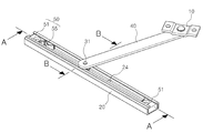
도 1은 본 고안의 실시예에 따른 회동식 창호용 스테이바의 사시도,
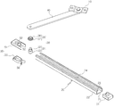
도 2는 본 고안의 실시예에 따른 회동식 창호용 스테이바의 일방향 분해사시도,
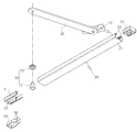
도 3은 본 고안의 실시예에 따른 회동식 창호용 스테이바의 타방향 분해사시도,
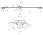
도 4는 도 1의 A-A선을 취하여 본 단면구조도,
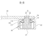
도 5는 도 1의 B-B선을 취하여 본 단면구조도,
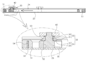
도 6은 도 4에서 슬라이더가 이동한 상태의 단면구조도,
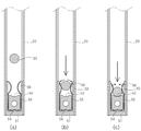
도 7은 본 고안의 실시예에 따른 회동식 창호용 스테이바에서 슬라이더가 스토퍼에 삽입되는 과정을 도시한 과정도,
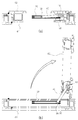
도 8은 본 고안의 실시예에 따른 스테이바가 장착된 회동식 창호가 개폐된 상태를 도시한 구조도.1 is a perspective view of a rotatable window stay bar according to an embodiment of the present invention,
2 is an exploded perspective view showing one-way disassembly of a rotatable window stay bar according to an embodiment of the present invention;
Fig. 3 is an exploded perspective view of a rotatable window stay bar according to an embodiment of the present invention,
Fig. 4 is a cross-sectional view taken along line AA of Fig. 1,
Fig. 5 is a cross-sectional structural view taken along line BB in Fig. 1,
FIG. 6 is a cross-sectional view of the slider moved in FIG. 4,
FIG. 7 is a process diagram illustrating a process of inserting a slider into a stopper in a rotatable window stay bar according to an embodiment of the present invention;
8 is a structural view showing a state in which a rotatable window equipped with a stay bar is opened and closed according to an embodiment of the present invention;
본 고안은 창문이 창틀에 회전 가능하게 힌지결합된 창호에서 창틀 및 창문에 결합되어 개폐되는 창문의 회전각도를 규제하는 회동식 창호용 스테이바에 관한 것으로써, 도 1 내지 도 8에 도시된 베이스부재(10)와, 가이드레일(20)과, 슬라이더(30)와, 링크부재(40)와, 스토퍼(50)를 포함하여 이루어진다.The present invention relates to a rotatable window stay bar for restricting a rotation angle of a window which is coupled to a window frame and a window in a window in which the window is rotatably hinged to the window frame, A
상기 베이스부재(10)는 창틀(61) 또는 창문(62) 중 어느 하나에 고정 결합된다.The
상기 가이드레일(20)은 창틀(61) 또는 창문(62) 중 나머지 하나에 고정 결합된다.The
본 실시예에서는 상기 베이스부재(10)가 창문(62)에 고정 결합되어 있고, 상기 가이드레일(20)이 상기 창틀(61)에 고정 결합되어 있다.In this embodiment, the
상기 가이드레일(20)은 긴 막대형상을 이루며, 저면부(21)와, 측벽부와, 절곡부(23)로 구성되어 단면이 대략 '∪'형상으로 형성된다.The
상기 저면부(21)는 바닥면을 형성하는 것으로써, 상기 창틀(61)에 접하여 결합되는 부분이다.The
상기 측벽부는 상기 저면부(21)의 양측에서 상호 이격되어 상방향으로 돌출된다.The side wall portions are spaced apart from each other at both sides of the
상기 절곡부(23)는 상호 이격된 한 쌍의 상기 측벽부의 상단에서 상호 마주보는 방향으로 절곡 형성되어 그 사이에 레일홈(24)을 형성한다.The
이로 인해, 상기 레일홈(24)의 폭은 상기 측벽부의 이격거리보다 짧다.Therefore, the width of the
상기 슬라이더(30)는 상기 가이드레일(20)을 따라 이동하는 것으로써, 상기 가이드레일(20)에 이동 가능하게 장착된다.The
상기 링크부재(40)는 긴 막대 형상으로 이루어지고, 일단이 상기 베이스부재(10)에 힌지결합되며 타단이 상기 슬라이더(30)에 결합된다.One end of the
상기 슬라이더(30)는 고정핀(31)과 롤러(35)로 이루어진다.The
상기 고정핀(31)은 상기 링크부재(40)의 일단에 결합된다.The
이때, 상기 고정핀(31)은 상기 링크부재(40)의 일단에 고정결합될 수도 있고, 회전 가능하게 결합될 수도 있다.At this time, the
상기 롤러(35)는 상기 고정핀(31)의 직경보다 큰 직경을 가지며, 상기 링크부재(40)의 하부에서 상기 고정핀(31)의 둘레에 회전 가능하게 결합된다.The
이러한 상기 롤러(35)는 상기 창문(62)의 개폐시 상기 링크부재(40)의 이동에 의해 상기 가이드레일(20)을 따라 이동하면서 상기 가이드레일(20)에 접하여 회전하게 된다.The
위와 같이 상기 링크부재(40)에 의한 상기 고정핀(31)의 이동시 상기 롤러(35)가 상기 가이드레일(20)에 접하여 회전함으로써, 상기 슬라이더(30)가 상기 가이드레일(20)을 따라 보다 용이하게 이동되도록 할 수 있다.The
보다 구체적으로, 상기 고정핀(31)은 결합부(32)와 지지부(33)로 이루어진다.More specifically, the
상기 결합부(32)는 상기 지지부(33)보다 상부에 위치하고, 상기 롤러(35)가 회전 가능하게 결합되는 부분이다.The
상기 지지부(33)는 상기 결합부(32)의 하부에 상기 결합부(32)의 직경보다 큰 직경으로 형성되어 상기 롤러(35)를 지지한다.The supporting
이러한 상기 결합부(32)는 상기 레일홈(24)에 배치되고, 상기 지지부(33)는 상기 가이드레일(20)의 안쪽에 배치된다.The
상기 롤러(35)는 상부접촉부(36)와 하부접촉부(37)로 이루어진다.The
상기 상부접촉부(36)는 한 쌍의 상기 절곡부(23) 사이에 형성된 상기 레일홈(24)에 삽입 배치되는 부분이다.The
상기 하부접촉부(37)는 상기 상부접촉부(36)의 하부에 형성되어 상기 레일홈(24)의 하부에 배치되는 부분으로써, 상기 하부접촉부(37)의 하부는 상기 지지부(33)에 의해 지지된다.The
그리고, 상기 하부접촉부(37)의 직경은 상기 레일홈(24)의 간격보다 크게 형성되어 상기 롤러(35)가 상기 절곡부(23)에 접하여 상방향으로의 이탈이 저지됨으로써, 상기 가이드레일(20)에 삽입 장착된 상기 슬라이더(30)가 상기 가이드레일(20)의 길이방향에 대한 수직방향으로 분리 이탈되는 것을 방지할 수 있다.The diameter of the
상기 스토퍼(50)는 상기 가이드레일(20)에 장착되어 상기 슬라이더(30)의 이동을 저지하는 것으로서, 본 실시예에서 상기 스토퍼(50)는 상기 가이드레일(20)의 양끝단에 장착되어 있다.The
이러한 상기 스토퍼(50)는 상기 가이드레일(20)에 삽입 장착되는 정지블럭(51)으로 이루어진다.The
상기 정지블럭(51)의 일면에는 상기 슬라이더(30)의 이동시 상기 고정핀(31)의 상기 지지부(33)가 안착되는 제1안착홈(52)과, 상기 제1안착홈(52)의 상부에서 상기 롤러(35)의 하부접촉부(37)가 안착되는 제2안착홈(53)이 형성되어 있다.A
상기 스토퍼(50)는 판스프링(55)을 더 포함하여 이루어진 수도 있다.The
상기 판스프링(55)은 두께가 두꺼운 면이 상기 고정핀(31)의 길이방향으로 배치되어 상기 정지블럭(51)에 결합된다.The
보다 구체적으로, 상기 판스프링(55)은 단면이 대략 '⊂'형상으로 형성되어, 일단이 상기 정지블럭(51)의 안쪽에 결합되고 타단이 상기 슬라이더(30) 방향으로 개방되게 배치된다.More specifically, the
상기 정지블럭(51)에는 상기 판스프링(55)이 삽입 배치되는 장착홈(54)이 형성되어 있다.The
그리고, 상기 판스프링(55)의 타단에는 상기 슬라이더(30)의 이동시 상기 고정핀(31)의 지지부(33)가 삽입되는 한쌍의 탄성절곡부(56)가 상호 이격되어 형성된다.A pair of
상기 탄성절곡부(56) 사이의 간격은 상기 고정핀(31)의 상기 지지부(33)의 직경보다 작게 형성되어 상기 지지부(33)의 통과시 상기 탄성절곡부(56)는 탄성변형되고, 상기 탄성절곡부(56)를 탄성변형시키면서 통과한 상기 지지부(33)는 상기 제1안착홈(52) 및 제2안착홈(53)에 안착되어 그 이동이 정지된다.The gap between the
그리고, 상기 탄성절곡부(56)의 상면은 상기 롤러(35)의 하면보다 하부에 위치하여, 상기 롤러(35)가 상기 판스프링(55)에 의해 회전이 저지되는 것을 방지하다.The upper surface of the
위와 같은 본 고안의 회동식 창호용 스테이바는 아래와 같은 과정을 통해 작동된다.The above-described stove bar of the present invention is operated through the following process.
도 8(a)에 도시된 바와 같이 창문(62)이 닫힌 상태에서 상기 슬라이더(30)는 상기 가이드레일(20)의 중간부위쯤에 위치한다.8 (a), the
이러한 상태에서 상기 창문(62)을 열게 되면, 도 8(b)에 도시된 바와 같이 상기 슬라이더(30)는 상기 가이드레일(20)을 따라 오른쪽으로 이동하게 된다.When the
이때, 상기 롤러(35)는 상기 가이드레일(20)에 접하면서 회전하게 되고, 이로 인해 상기 가이드레일(20)과 슬라이더(30) 간의 접촉에 따른 마찰력이 작아지면서 상기 슬라이더(30)는 상기 가이드레일(20)을 따라 보다 신속하고 용이하게 이동할 수 있게 된다.At this time, the
도 7(a)에 도시된 바와 같이 상기 고정핀(31)의 지지부(33)가 상기 스토퍼(50)에 근접하게 된 후 더 이동하게 되면, 도 7(b)에 도시된 바와 같이 상기 탄성절곡부(56)는 상기 지지부(33)에 의해 서로 멀어지는 방향으로 탄성변형되게 되고, 상기 지지부(33)가 상기 탄성절곡부(56)를 통과하게 되면 도 7(c)에 도시된 바와 같이 상기 탄성절곡부(56)는 원상복원된다.7 (a), when the supporting
이때, 상기 지지부(33)는 상기 제1안착홈(52)에 안착되고, 상기 하부접촉부(37)는 상기 제2안착부에 안착되어 그 이동이 정지된다.At this time, the
위와 같이 상기 슬라이더(30)가 상기 탄성절곡부(56)를 통과함으로써, 상기 슬라이더(30)는 상기 스토퍼(50)에 의해 그 이동이 정지되고, 이로 인해 개방된 상기 창문(62)이 바람 등의 외력에 의해 임의로 닫히는 것을 방지할 수 있다.The
한편, 개방된 창문(62)을 닫고자 할 경우에는 상기 창문(62)을 창틀(61) 방향으로 잡아당김으로써, 상술한 방법의 역방법으로 작동되면서 상기 슬라이더(30)가 상기 가이드레일(20)을 따라 왼쪽으로 이동하게 된다.On the other hand, when the user wishes to close the opened
위와 같이 본 고안은 상기 가이드레일(20)을 따라 이동하는 상기 슬라이더(30)에 롤러(35)가 장착되어 있음으로써, 상기 슬라이더(30)의 이동시 상기 롤러(35)의 회전에 의해 상기 슬라이더(30)가 보다 신속하고 용이하게 이동할 수 있다.The
본 고안인 회동식 창호용 스테이바는 전술한 실시예에 국한하지 않고, 본 고안의 기술 사상이 허용되는 범위 내에서 다양하게 변형하여 실시할 수 있다.The present invention is not limited to the above-described embodiments, but can be variously modified within the scope of the technical idea of the present invention.
10 : 베이스부재,
20 : 가이드레일, 21 : 저면부, 22 : 측벽부, 23 : 절곡부, 24 : 레일홈,
30 : 슬라이더, 31 : 고정핀, 32 : 결합부, 33 : 지지부, 35 : 롤러, 36 : 상부접촉부, 37 : 하부접촉부,
40 : 링크부재,
50 : 스토퍼, 51 : 정지블럭, 52 : 제1안착홈, 53 : 제2안착홈, 54 : 장착홈, 55 : 판스프링, 56 : 탄성절곡부,
61 : 창틀, 62 : 창문.10: base member,
20: guide rail, 21: bottom surface portion, 22: side wall portion, 23: bent portion, 24: rail groove,
The present invention relates to an image forming apparatus and a method of manufacturing the same. The image forming apparatus includes a slider, a fixing pin,
40: link member,
The present invention relates to a stopper and a method of manufacturing the same. More particularly, the present invention relates to a stopper,
61: window frame, 62: window.
Claims (6)
창틀 또는 창문 중 어느 하나에 고정 결합되는 베이스부재와;
창틀 또는 창문 중 나머지 하나에 고정 결합되는 가이드레일과;
상기 가이드레일을 따라 이동하도록 장착된 슬라이더와;
일단이 상기 베이스부재에 힌지결합되고, 타단이 상기 슬라이더에 결합된 링크부재와;
상기 가이드레일에 장착되어 상기 슬라이더의 이동을 저지하는 스토퍼;를 포함하여 이루어지되,
상기 슬라이더는,
상기 링크부재의 일단에 결합된 고정핀과;
상기 고정핀의 직경보다 큰 직경을 가지며 상기 링크부재의 하부에서 상기 고정핀의 둘레에 회전 가능하게 결합된 롤러;로 이루어지며,
상기 창문의 개폐시 상기 링크부재의 이동에 의해 상기 롤러는 상기 가이드레일을 따라 이동하면서 상기 가이드레일에 접하여 회전되는 것을 특징으로 하는 회동식 창호용 스테이바.1. A rotatable window stay bar for restricting a rotation angle of a window that is coupled to a window frame and a window in a window in which the window is rotatably hinged to the window frame,
A base member fixedly coupled to either the window frame or the window;
A guide rail fixedly coupled to the other one of the window frame and the window;
A slider mounted to move along the guide rail;
A link member having one end hinged to the base member and the other end coupled to the slider;
And a stopper mounted on the guide rail to prevent movement of the slider,
The slider
A fixing pin coupled to one end of the link member;
And a roller having a diameter larger than the diameter of the fixing pin and rotatably coupled to a periphery of the fixing pin at a lower portion of the link member,
Wherein the roller is rotated in contact with the guide rail while moving along the guide rail by movement of the link member when the window is opened and closed.
상기 가이드레일은,
저면부와;
상기 저면부의 양측에서 상방향으로 돌출된 측벽부와;
상호 이격된 한 쌍의 상기 측벽부의 상단에서 상호 마주보는 방향으로 절곡 형성되어 그 사이에 레일홈을 형성하는 절곡부;로 이루어지고,
상기 롤러는,
한 쌍의 상기 절곡부 사이에 형성된 상기 레일홈에 삽입 배치되는 상부접촉부와;
상기 상부접촉부의 하부에 형성되어 상기 레일홈의 하부에 배치되는 하부접촉부로 이루어지며,
상기 하부접촉부의 직경은 상기 레일홈의 간격보다 크게 형성되어 상기 롤러가 상기 절곡부에 접하여 상방향으로의 이탈이 저지되는 것을 특징으로 하는 회동식 창호용 스테이바.The method according to claim 1,
The guide rails
A bottom portion;
A side wall portion protruding upward from both sides of the bottom portion;
And a bent portion formed at an upper end of the pair of spaced apart side wall portions so as to be bent in a direction opposite to each other and forming a rail groove therebetween,
The roller
An upper contact portion inserted into the rail groove formed between the pair of bent portions;
And a lower contact portion formed at a lower portion of the upper contact portion and disposed at a lower portion of the rail groove,
Wherein a diameter of the lower contact portion is formed to be larger than an interval of the rail groove, so that the roller comes into contact with the bent portion to prevent the upward departure of the roller.
상기 고정핀은,
상기 롤러가 회전 가능하게 결합되는 결합부와;
상기 결합부의 하부에서 상기 결합부의 직경보다 큰 직경으로 형성되어 상기 롤러를 지지하고 상기 가이드레일의 안쪽에 배치되는 지지부;로 이루어진 것을 특징으로 하는 회동식 창호용 스테이바.The method of claim 2,
Wherein the fixing pin includes:
An engaging portion to which the roller is rotatably engaged;
And a supporting portion formed at a lower portion of the coupling portion and having a diameter larger than a diameter of the coupling portion, the support portion supporting the roller and disposed inside the guide rail.
상기 스토퍼는,
상기 가이드레일에 삽입 장착된 정지블럭;을 포함하여 이루어지되,
상기 정지블럭의 일면에는 상기 슬라이더의 이동시 상기 지지부가 안착되는 제1안착홈과, 상기 제1안착홈의 상부에서 상기 롤러의 하부접촉부가 안착되는 제2안착홈이 형성된 것을 특징으로 하는 회동식 창호용 스테이바.The method of claim 3,
The stopper
And a stop block inserted into the guide rail,
Wherein a first seating groove on which the support portion is seated when the slider is moved and a second seating groove on which the lower contact portion of the roller is seated are formed on one surface of the stop block, For stay bar.
상기 스토퍼는,
일단이 상기 정지블럭의 안쪽에 결합되고 타단이 상기 슬라이더 방향으로 개방된 판스프링;을 더 포함하여 이루어지되,
상기 정지블럭에는 상기 판스프링이 삽입 배치되는 장착홈이 형성되고,
상기 판스프링의 타단에는 상기 슬라이더의 이동시 상기 고정핀의 지지부가 삽입되는 한쌍의 탄성절곡부가 상호 이격되어 형성되며,
상기 탄성절곡부 사이의 간격은 상기 지지부의 직경보다 작게 형성되어 상기 지지부의 통과시 상기 탄성절곡부는 탄성변형되고,
상기 탄성절곡부를 탄성변형시키면서 통과한 상기 지지부 및 하부접촉부는 상기 제1안착홈 및 제2안착홈에 안착되어 그 이동이 정지되는 것을 특징으로 하는 회동식 창호용 스테이바.The method of claim 4,
The stopper
And a leaf spring having one end coupled to the inside of the stop block and the other end opened in the slider direction,
Wherein the stop block is formed with a mounting groove into which the leaf spring is inserted,
And a pair of elastic bending portions, into which the support portion of the fixing pin is inserted when the slider is moved, are spaced apart from each other at the other end of the leaf spring,
Wherein a distance between the elastic bending portions is smaller than a diameter of the supporting portion so that the elastic bending portion elastically deforms when the supporting portion passes,
Wherein the support portion and the lower contact portion, which have passed through the elastic bending portion while elastically deforming, are seated in the first and second seating grooves to stop the movement thereof.
상기 탄성절곡부의 상면은 상기 롤러의 하면보다 하부에 위치하는 것을 특징으로 하는 회동식 창호용 스테이바.
The method of claim 5,
And the upper surface of the elastic bending portion is located below the lower surface of the roller.
Priority Applications (1)
| Application Number | Priority Date | Filing Date | Title |
|---|---|---|---|
| KR2020160006355U KR20180001371U (en) | 2016-10-31 | 2016-10-31 | Stay Bar for Turning Type Window |
Applications Claiming Priority (1)
| Application Number | Priority Date | Filing Date | Title |
|---|---|---|---|
| KR2020160006355U KR20180001371U (en) | 2016-10-31 | 2016-10-31 | Stay Bar for Turning Type Window |
Publications (1)
| Publication Number | Publication Date |
|---|---|
| KR20180001371U true KR20180001371U (en) | 2018-05-10 |
Family
ID=62166195
Family Applications (1)
| Application Number | Title | Priority Date | Filing Date |
|---|---|---|---|
| KR2020160006355U Abandoned KR20180001371U (en) | 2016-10-31 | 2016-10-31 | Stay Bar for Turning Type Window |
Country Status (1)
| Country | Link |
|---|---|
| KR (1) | KR20180001371U (en) |
Cited By (3)
| Publication number | Priority date | Publication date | Assignee | Title |
|---|---|---|---|---|
| CN110356208A (en) * | 2019-08-28 | 2019-10-22 | 上海三一重机股份有限公司 | A kind of fan-folded door and cab door |
| KR20230072864A (en) * | 2021-11-18 | 2023-05-25 | 동국대학교 와이즈캠퍼스 산학협력단 | two way swing door |
| KR102574735B1 (en) * | 2023-04-25 | 2023-09-06 | 주식회사 미맥스 | Opening and closing device for turning type windows |
Citations (6)
| Publication number | Priority date | Publication date | Assignee | Title |
|---|---|---|---|---|
| KR20090005688U (en) | 2007-12-06 | 2009-06-11 | 주식회사 대현상공 | Casement for casement door which can be fixed open |
| KR100944518B1 (en) * | 2009-09-28 | 2010-03-03 | 노승환 | Stay bar for turning type window |
| KR20100120007A (en) * | 2009-05-04 | 2010-11-12 | 노승환 | Stay bar for turning type window |
| JP2010265706A (en) * | 2009-05-17 | 2010-11-25 | Takigen Mfg Co Ltd | Two-stage stop type stay device |
| KR20100138293A (en) | 2009-06-25 | 2010-12-31 | 노승환 | Swivel Stay Bar |
| KR101487990B1 (en) * | 2013-08-30 | 2015-02-02 | 주식회사 대현상공 | Stay for tilting windows |
-
2016
- 2016-10-31 KR KR2020160006355U patent/KR20180001371U/en not_active Abandoned
Patent Citations (6)
| Publication number | Priority date | Publication date | Assignee | Title |
|---|---|---|---|---|
| KR20090005688U (en) | 2007-12-06 | 2009-06-11 | 주식회사 대현상공 | Casement for casement door which can be fixed open |
| KR20100120007A (en) * | 2009-05-04 | 2010-11-12 | 노승환 | Stay bar for turning type window |
| JP2010265706A (en) * | 2009-05-17 | 2010-11-25 | Takigen Mfg Co Ltd | Two-stage stop type stay device |
| KR20100138293A (en) | 2009-06-25 | 2010-12-31 | 노승환 | Swivel Stay Bar |
| KR100944518B1 (en) * | 2009-09-28 | 2010-03-03 | 노승환 | Stay bar for turning type window |
| KR101487990B1 (en) * | 2013-08-30 | 2015-02-02 | 주식회사 대현상공 | Stay for tilting windows |
Cited By (4)
| Publication number | Priority date | Publication date | Assignee | Title |
|---|---|---|---|---|
| CN110356208A (en) * | 2019-08-28 | 2019-10-22 | 上海三一重机股份有限公司 | A kind of fan-folded door and cab door |
| CN110356208B (en) * | 2019-08-28 | 2024-05-28 | 上海三一重机股份有限公司 | Folding sector door and cab door |
| KR20230072864A (en) * | 2021-11-18 | 2023-05-25 | 동국대학교 와이즈캠퍼스 산학협력단 | two way swing door |
| KR102574735B1 (en) * | 2023-04-25 | 2023-09-06 | 주식회사 미맥스 | Opening and closing device for turning type windows |
Similar Documents
| Publication | Publication Date | Title |
|---|---|---|
| EP3292801B1 (en) | Structure of non-interference front-surface opening/closing-type frame | |
| CN204476059U (en) | Slider guide structure and push-pull translational doors and windows provided with the slider guide structure | |
| JP2008180065A (en) | Guide device for mobile partition device | |
| JP5231439B2 (en) | Door lock device | |
| KR101138288B1 (en) | Stay Bar for Turning Type Window | |
| KR101043377B1 (en) | Swivel Stay Bar | |
| KR20130087796A (en) | Sliding window having airtight apparatus | |
| JP4545808B2 (en) | Interlocking sliding door device | |
| KR20130087797A (en) | Sliding window having airtight apparatus | |
| KR20090131872A (en) | Windows for project and casement movements with improved hinges | |
| KR20190001469U (en) | The height control structure of roller for sliding door | |
| KR101809790B1 (en) | Stay Bar for Turning Type Window | |
| JP5013610B2 (en) | Bearing stopper with gap closing mechanism for hanging door runner | |
| KR200188830Y1 (en) | Roller assembly for sliding door | |
| KR101794259B1 (en) | Interlocking device of sliding door | |
| CN204691490U (en) | Stop device and door and window | |
| KR200389929Y1 (en) | Opening/shutting device for slide door of reefer | |
| KR200325944Y1 (en) | Roller assembly for sliding door | |
| JPS6340614Y2 (en) | ||
| JP2007182675A (en) | Guide of top-hinged swinging door | |
| KR101861799B1 (en) | Window roller | |
| CN105888421B (en) | A kind of door leaf rotating shaft and include the automobile of the door leaf rotating shaft | |
| JP2016079746A (en) | Closing operation suppressing structure of sliding door | |
| AU2013273854B2 (en) | Detachable hanger for covering of building’s opening | |
| JP2002227499A (en) | Sliding door mooring equipment |
Legal Events
| Date | Code | Title | Description |
|---|---|---|---|
| A201 | Request for examination | ||
| UA0108 | Application for utility model registration |
Comment text: Application for Utility Model Registration Patent event code: UA01011R08D Patent event date: 20161031 |
|
| UA0201 | Request for examination | ||
| E902 | Notification of reason for refusal | ||
| UE0902 | Notice of grounds for rejection |
Comment text: Notification of reason for refusal Patent event code: UE09021S01D Patent event date: 20180320 |
|
| E701 | Decision to grant or registration of patent right | ||
| UE0701 | Decision of registration |
Patent event date: 20180401 Comment text: Decision to Grant Registration Patent event code: UE07011S01D |
|
| UG1501 | Laying open of application | ||
| NORF | Unpaid initial registration fee | ||
| UC1904 | Unpaid initial registration fee |