JP4997367B2 - Surface inspection device - Google Patents
Surface inspection device Download PDFInfo
- Publication number
- JP4997367B2 JP4997367B2 JP2006143399A JP2006143399A JP4997367B2 JP 4997367 B2 JP4997367 B2 JP 4997367B2 JP 2006143399 A JP2006143399 A JP 2006143399A JP 2006143399 A JP2006143399 A JP 2006143399A JP 4997367 B2 JP4997367 B2 JP 4997367B2
- Authority
- JP
- Japan
- Prior art keywords
- inspection
- head
- light
- optical path
- axis
- Prior art date
- Legal status (The legal status is an assumption and is not a legal conclusion. Google has not performed a legal analysis and makes no representation as to the accuracy of the status listed.)
- Active
Links
- 238000007689 inspection Methods 0.000 title claims description 139
- 230000003287 optical effect Effects 0.000 claims description 46
- 238000003780 insertion Methods 0.000 claims description 19
- 230000037431 insertion Effects 0.000 claims description 19
- 230000007246 mechanism Effects 0.000 description 39
- 230000002093 peripheral effect Effects 0.000 description 16
- 238000012545 processing Methods 0.000 description 14
- 239000000853 adhesive Substances 0.000 description 6
- 230000001070 adhesive effect Effects 0.000 description 6
- 239000000835 fiber Substances 0.000 description 6
- 238000003860 storage Methods 0.000 description 6
- 230000005540 biological transmission Effects 0.000 description 5
- 238000001514 detection method Methods 0.000 description 5
- 238000000034 method Methods 0.000 description 4
- 238000004140 cleaning Methods 0.000 description 3
- 238000005520 cutting process Methods 0.000 description 3
- 230000001771 impaired effect Effects 0.000 description 3
- 238000005259 measurement Methods 0.000 description 3
- 230000007423 decrease Effects 0.000 description 2
- 239000000428 dust Substances 0.000 description 2
- 230000005484 gravity Effects 0.000 description 2
- 238000005304 joining Methods 0.000 description 2
- 238000012423 maintenance Methods 0.000 description 2
- 238000004590 computer program Methods 0.000 description 1
- 239000011521 glass Substances 0.000 description 1
- 238000004519 manufacturing process Methods 0.000 description 1
- 239000013307 optical fiber Substances 0.000 description 1
- 239000004065 semiconductor Substances 0.000 description 1
- 238000012360 testing method Methods 0.000 description 1
Images


Landscapes
- Investigating Materials By The Use Of Optical Means Adapted For Particular Applications (AREA)
Description
本発明は、被検査物の表面状態を検査する表面検査装置に関する。 The present invention relates to a surface inspection apparatus for inspecting the surface state of an object to be inspected.
被検査物の表面、例えば円筒状の被検査物の内面を検査する装置として、先端に光路変更手段が設けられた軸状の検査ヘッドを駆動機構により軸線の回りに回転させつつ軸線に沿って移動させるとともに、検査ヘッド内に軸線に沿って入射した検査光の光路を光路変更手段により変更し、光路が変更された検査光を、穴の内面に照射し、その内面で反射して該検査ヘッド内に再度入射した光の光量に基づいて内面状態を検出する表面検査装置が知れている(例えば、特許文献1参照)。この表面検査装置において検査ヘッドは、光路変更手段を含めて一体として形成されている。したがって光路変更手段が汚れた場合、検査ヘッド全体を駆動機構から取り外して光路変更手段の清掃が行われる。また、光路変更手段が破損した場合や、テーパを有する穴の内面を検査するためにその傾斜に合うように配置された光路変更手段が必要な場合は、検査ヘッド全体が交換される。
しかしながら、検査ヘッド全体を駆動機構から取り外して再度検査ヘッドを駆動機構に取り付ける場合、検査ヘッドの着脱作業に加えて、検査ヘッドと駆動機構との芯合わせも再度行う必要もあり、かなりの作業時間を要する。また、光路変更手段を交換する場合、検査ヘッドごと交換するため費用もかかるという問題もある。 However, when the entire inspection head is removed from the drive mechanism and the inspection head is reattached to the drive mechanism, it is necessary to realign the inspection head and the drive mechanism in addition to the inspection head attachment / detachment operation, which requires considerable work time. Cost. In addition, when the optical path changing means is replaced, there is a problem that it is expensive because the inspection head is replaced.
そこで本発明は、光路変更手段の清掃及び交換を安価で且つ容易に行うことのできる表面検査装置を提供することを目的とする。 Accordingly, an object of the present invention is to provide a surface inspection apparatus that can easily and inexpensively clean and replace the optical path changing means.
本発明の表面検査装置(1)は、先端に光路変更手段(18,118)が設けられた軸状の検査ヘッド(16,116)を駆動手段(30,40)により軸線(AX)の回りに回転させつつ前記軸線(AX)に沿って移動させるとともに、前記検査ヘッド(16,116)内に前記軸線(AX)に沿って入射した検査光の光路を前記光路変更手段(18,118)により変更し、該光路が変更された検査光を被検査物(100)に照射し、該被検査物(100)で反射して該検査ヘッド内(16,116)に再度入射した前記検査光の光量に基づいて前記被検査物(100)の表面状態を検出する表面検査装置(1)において、前記検査ヘッド(16,116)が、前記駆動手段(30,40)に取り付けられるヘッド本体(70,120)と、前記ヘッド本体(70,120)に対して着脱可能に設けられ且つ前記光路変更手段を保持する保持部(71,171)と、を備え、前記保持部(71,171)が、前記ヘッド本体(70,120)に対して着脱可能な外筒体(75,175)と、前記光路変更部材(18,180)を保持し且つ該外筒体の内部に着脱可能な内筒体(76,176)と、を備えていることを特徴とする。
In the surface inspection apparatus (1) of the present invention, an axial inspection head (16, 116) provided with an optical path changing means (18, 118) at its tip is moved around an axis (AX) by a driving means (30, 40). The optical path changing means (18, 118) changes the optical path of the inspection light incident along the axis (AX) into the inspection head (16, 116). The inspection light that has been changed by the above-described method, the inspection light whose optical path is changed is irradiated onto the inspection object (100), is reflected by the inspection object (100), and is incident on the inspection head (16, 116) again. In the surface inspection apparatus (1) for detecting the surface state of the object to be inspected (100) based on the amount of light, the head body (16, 116) is attached to the drive means (30, 40). 70, 120) Comprises a holding portion (71, 171) for holding and said optical path changing means capable provided detachably with respect to said head body (70,120), wherein the holding portion (71, 171), said head body An outer cylinder (75, 175) detachably attached to (70, 120), and an inner cylinder (76, 76) that holds the optical path changing member (18, 180) and is detachable inside the outer cylinder. 176) .
この表面検査装置によれば、検査ヘッドが、駆動手段に取り付けられたヘッド本体と、光路変更手段を保持する保持部との2つの部材で構成され、ヘッド本体に対して保持部が着脱可能であるため、光路変更手段を交換する場合、駆動手段に取り付けられたヘッド本体はそのままにして、保持部のみ取り外して交換することができる。また、ヘッド本体に対して着脱可能な外筒体から光路変更部材を保持する内筒体がさらに着脱可能であるため、光路変更部材を交換する場合、内筒体のみ交換すればよく、より安価に対応できる。
According to this surface inspection apparatus, the inspection head is composed of two members, a head main body attached to the driving means and a holding portion for holding the optical path changing means, and the holding portion can be attached to and detached from the head main body. Therefore, when exchanging the optical path changing means, the head body attached to the driving means can be left as it is, and only the holding part can be removed and exchanged. In addition, since the inner cylinder holding the optical path changing member can be further detached from the outer cylinder that can be attached to and detached from the head body, when replacing the optical path changing member, it is only necessary to replace the inner cylinder, which is less expensive. It can correspond to.
また、本発明の一形態において、前記保持部(71)は前記検査ヘッド(16)の先端側に限定して設けられていてもよい。これによれば、着脱される保持部が、検査ヘッドの先端側に限定して設けられているので、保持部を短く製造することができ、交換部品を安価に製造することができる。 In one embodiment of the present invention, the holding portion (71) may be limited to the tip side of the inspection head (16). According to this, since the attaching / detaching holding part is provided only on the tip side of the inspection head, the holding part can be manufactured short, and the replacement part can be manufactured inexpensively.
さらに、本発明の一形態において、前記検査ヘッド(116)が前記被検査物(100)に挿入される挿入部(181)を有し、前記保持部(171)が、前記挿入部(181)よりも前記駆動手段(30,40)側まで延びていてもよい。 Furthermore, in one form of this invention, the said test | inspection head (116) has an insertion part (181) inserted in the said to-be-inspected object (100), and the said holding | maintenance part (171) is the said insertion part (181). It may extend to the drive means (30, 40) side.
これによると、交換可能な保持部が挿入部よりも駆動手段側まで延びているため、例えば、種々の長さを有する保持部を予め用意しておけば、検査する穴の内面の深さ応じて適当な長さの保持部に即座に交換することができる。また、ヘッド本体と保持部との接合部はねじ等の着脱構造が必要なため、他の部分よりも厚みが必要となるが、本形態によれば、保持部が挿入部よりも駆動手段側まで延びているため、接合位置が挿入部の外側となる。したがって挿入部に接合部が存在しないため、挿入部を細くすることが可能で、小さな穴の内部を検査可能なように先の細い検査ヘッドを製造することができる。 According to this, since the replaceable holding portion extends to the drive means side from the insertion portion, for example, if holding portions having various lengths are prepared in advance, the depth of the inner surface of the hole to be inspected can be adjusted. Thus, it is possible to immediately replace the holding unit with an appropriate length. In addition, since the joint portion between the head body and the holding portion requires a detachable structure such as a screw, the thickness is required more than other portions. According to this embodiment, the holding portion is closer to the driving means than the insertion portion. Therefore, the joining position is outside the insertion portion. Therefore, since there is no joining portion in the insertion portion, the insertion portion can be made thin, and a thin inspection head can be manufactured so that the inside of a small hole can be inspected.
また、本発明の一形態において前記外筒体(75,175)は、その先端(175a)が閉じられ且つ筒状側面に透光穴(75b,175b)が設けられ、前記内筒体(76,176)は、その両端が開口し且つ筒状側面に透光部材(76a,176a)がはめ込まれた透光穴(76a,176a)が設けられるとともに、前記筒状側面の内面に前記透光穴(76a,176a)に対して対称となるように前記内筒体(76,176)の軸線(AX)に対して所定の角度でスリット(76c,176c)が設けられていてもよい。 Further , in one embodiment of the present invention, the outer cylinder (75, 175) has a distal end (175a) closed and a light transmitting hole (75b, 175b) provided on the cylindrical side surface, and the inner cylinder (76). , 176) are provided with translucent holes (76a, 176a) in which both ends are open and translucent members (76a, 176a) are fitted in the cylindrical side surface, and the translucent hole is formed on the inner surface of the cylindrical side surface. hole (76a, 176a) slits (76c, 176c) at a predetermined angle relative to the axis (AX) of said cylindrical body so as to be symmetric with respect to (76, 176) may be provided with.
これによると、内筒体のスリットに、例えばミラーである矩形又は円形の光路変更部材の両端を挟んで挿入することができ、スリットの角度を検査対象となる穴の傾斜に合わせて製造することで光路変更部材の角度を容易に一定の角度で保持することができる。また、内筒体の両端が開口しているため、光路変更部材を内筒体のスリットに装着した後でも、光路変更部材によって分割された内筒体の内部の両空間へのアクセスが容易である。したがって、内筒体全体としてバランスが悪い場合は、外筒体に取り付ける前に、光路変更部材の裏面の空間内において、例えば接着剤を位置や量を調整することにより、バランス調整を容易に行うことができる。また、光路変更部材の表面が汚れている場合、その汚れを容易に拭き取ることができる。さらに、内筒体は先端が閉じられた外筒体に挿入されるため、接着剤等によってバランス調整された空間は外側から目視できなくなり、外観が損なわれることもない。内筒体及び外筒体には透光穴が設けられているため、光路変更部材によって光路が変更された検査光は、これらの透光穴を通って被検査物に照射可能であるが、内筒体の透光穴には透光部材が嵌め込まれているため、検査ヘッド内部へのごみ等の侵入が防止される。 According to this, it is possible to insert the both ends of a rectangular or circular optical path changing member that is a mirror, for example, into the slit of the inner cylindrical body, and manufacture the slit according to the inclination of the hole to be inspected. Thus, the angle of the optical path changing member can be easily held at a constant angle. In addition, since both ends of the inner cylinder are open, it is easy to access both spaces inside the inner cylinder divided by the optical path changing member even after the optical path changing member is attached to the slit of the inner cylinder. is there. Therefore, if the overall balance of the inner cylinder is poor, the balance can be easily adjusted, for example, by adjusting the position and amount of the adhesive in the space on the back surface of the optical path changing member before being attached to the outer cylinder. be able to. Moreover, when the surface of the optical path changing member is dirty, the stain can be easily wiped off. Furthermore, since the inner cylinder is inserted into the outer cylinder whose tip is closed, the space adjusted by an adhesive or the like cannot be seen from the outside, and the appearance is not impaired. Since the inner cylinder and the outer cylinder are provided with translucent holes, the inspection light whose optical path has been changed by the optical path changing member can irradiate the inspection object through these translucent holes. Since a translucent member is fitted in the translucent hole of the inner cylinder, intrusion of dust and the like into the inspection head is prevented.
なお、以上の説明では本発明の理解を容易にするために添付図面の参照符号を括弧書きにて付記したが、それにより本発明が図示の形態に限定されるものではない。 In addition, in the above description, in order to make an understanding of this invention easy, the reference sign of the accompanying drawing was attached in parenthesis, but this invention is not limited to the form of illustration by it.
以上説明したように本発明によると、検査ヘッドにおいて、光路変更手段の保持部がヘッド本体に対して着脱可能であるため、光路変更手段を交換する場合、駆動手段に取り付けられたヘッド本体は取り外さずに、保持部のみ取り外して交換することができる。故に、光路変更手段の清掃及び交換を安価で且つ容易に行うことができる。 As described above, according to the present invention, in the inspection head, since the holding portion of the optical path changing means is detachable from the head main body, when replacing the optical path changing means, the head main body attached to the driving means is removed. Instead, only the holding part can be removed and replaced. Therefore, cleaning and replacement of the optical path changing means can be performed inexpensively and easily.
[第一形態] [First form]
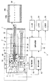
図1は、本発明の第一形態にかかる表面検査装置1の概略構成を示している。表面検査装置1は、被検査物100に設けられた円筒形の内周面100aの検査に適した装置であり、検査を実行するための検査機構2と、その検査機構2の動作制御、検査機構2による測定結果の処理等を実行するための制御部3とを備えている。さらに、検査機構2は、被検査物100に対して検査光を投光し、かつ被検査物100からの反射光を受光する検出ユニット5とその検出ユニット5に所定の動作を与える駆動ユニット6とを備えている。
FIG. 1 shows a schematic configuration of a surface inspection apparatus 1 according to the first embodiment of the present invention. The surface inspection apparatus 1 is an apparatus suitable for inspecting a cylindrical inner
検出ユニット5は、検査光の光源としてのレーザダイオード(LD)11と、被検査物100からの反射光を受光し、その反射光の単位時間当たりの光量(反射光強度)に応じた電流又は電圧の電気信号を出力するフォトディテクタ(以下、PDと呼ぶ)12と、LD11から照射される検査光を被検査物100に向って導く投光ファイバ13と、被検査物100からの反射光をPD12に導くための受光ファイバ14と、それらのファイバ13、14を束ねた状態で保持する保持筒15と、その保持筒15の外側に同軸的に設けられる中空軸状の検査ヘッド16とを備えている。なお、検査ヘッド16については後に詳述する。保持筒15の先端には投光ファイバ13を介して導かれた検査光を検査ヘッド16の軸線AXの方向(以下、軸線AX方向と呼ぶ)に沿ってビーム状に射出させ、かつ検査ヘッド16の軸線AX方向に沿って検査光とは逆向きに進む反射光を受光ファイバ14に集光するレンズ17が設けられ、検査ヘッド16の先端には(図1において右端部)には、光路変更手段としてのミラー18が設けられている。
The
駆動ユニット6は、直線駆動機構30と、回転駆動機構40と、焦点調節機構50とを備えている。直線駆動機構30は、検査ヘッド16をその軸線AX方向に移動させるための直線駆動手段として設けられている。そのような機能を実現するために、直線駆動機構30はベース31と、そのベース31に固定された一対のレール32と、レール32に沿って検査ヘッド16の軸線AX方向に移動可能なスライダ33と、そのスライダ33の側方に検査ヘッド16の軸線AXと平行に配置された送りねじ34と、その送りねじ34を回転駆動する電動モータ35とを備えている。スライダ33は検出ユニット5の全体を支持する手段として機能する。すなわち、LD11及びPD12はスライダ33に固定され、検査ヘッド16は回転駆動機構40を介してスライダ33に取り付けられ、保持筒15は焦点調節機構50を介してスライダ33に取り付けられている。さらに、送りねじ34はスライダ33に固定されたナット36にねじ込まれている。したがって、電動モータ35にて送りねじ34を回転駆動することにより、スライダ33がレール32に沿って検査ヘッド16の軸線AX方向に移動し、それに伴ってスライダ33に支持された検出ユニット5の全体が検査ヘッド16の軸線AX方向に移動する。直線駆動機構30を用いた検出ユニット5の駆動により被検査物100の内周面100aに対する検査光の照射位置を検査ヘッド16の軸線AX方向に関して変化させることができる。
The
回転駆動機構40は、検査ヘッド16を軸線AXの回りに回転させる回転駆動手段として設けられている。そのような機能を実現するため、回転駆動機構40は、検査ヘッド16を軸線AXの回りに回転自在に支持するように、保持筒15と検査ヘッド16との間に取り付けられた軸受39と、回転駆動源としての電動モータ41と、その電動モータ41の回転を検査ヘッド16に伝達する伝達機構としてのベルト42を備える。なお、伝達機構は、ベルト42に限定されず、歯車列等の他の回転伝達機構を利用することもできる。電動モータ41の回転をベルト42を介して検査ヘッド16に伝達することにより、検査ヘッド16がミラー18を伴って軸線AXの回りに回転する。回転駆動機構40を用いた検査ヘッド16の回転により、被検査物100の内周面100aに対する検査光の照射位置を被検査物100の周方向に関して変化させることができる。そして検査ヘッド16の軸方向への移動と軸線AXの回りの回転とを組み合わせることにより、検査物の内周面100aをその全面に亘って検査光で走査することが可能となる。
The
焦点調節機構50は、検査光が被検査物100の内周面100aにて焦点を結ぶように保持筒15を軸線AXの方向に駆動する焦点調整手段として設けられている。その機能を実現するために、焦点調節機構50は、保持筒15の基端部に固定された支持板51と、直線駆動機構30のスライダ33と支持板51との間に配置されて支持板51を検査ヘッド16の軸線AX方向に案内するレール52と、検査ヘッド16の軸線AXと平行に配置されて支持板51にねじ込まれた送りねじ53と、その送りねじ53を回転駆動する電動モータ54とを備えている。電動モータ54にて送りねじ53を回転駆動することにより、支持板51がレール52に沿って移動して保持筒15が検査ヘッド16の軸線AX方向に移動する。これにより、検査光が被検査物100の内周面100a上で、焦点を結ぶようにレンズ17からミラーを経て内周面100aに至る光路の長さを調節することができる。
The
制御部3は、表面検査装置1による検査工程の管理、測定結果の処理等を実行するコンピュータユニットとしての演算処理部60と、その演算処理部60の指示に従って検査機構2の各部の動作を制御する動作制御部61と、PD12の出力信号に対して所定の処理を実行する信号処理部62と、演算処理部60に対してユーザが指示を入力するための入力部63と、演算処理部60における測定結果等をユーザに提示するための出力部64と、演算処理部60にて実行すべきコンピュータプログラム、及び、測定されたデータ等を記憶する記憶部65とを備えている。演算処理部60、入力部63、出力部64及び記憶部65はパーソナルコンピュータ等の汎用コンピュータ機器を利用してこれらを構成することができる。この場合、入力部63にはキーボード、マウス等の入力機器が設けられ、出力部64にはモニタ装置が設けられる。プリンタ等の出力機器が出力部64に追加されてもよい。記憶部65には、ハードディスク記憶装置、あるいは記憶保持が可能な半導体記憶素子等の記憶装置が用いられる。動作制御部61及び信号処理部62は、ハードウエア制御回路によって実現されてもよいし、コンピュータによって実現されてもよい。
The
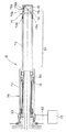
図2は、検査ヘッド16の拡大図である。検査ヘッド16は、上述したように、電動モータ41にベルト42を介して取り付けられたヘッド本体70と、ヘッド本体70の先端に着脱可能に設けられ且つミラー18を保持する保持部71とを備える。
FIG. 2 is an enlarged view of the
ヘッド本体70は、保持筒15の回りに軸受39を介して回転可能に装着される保持筒外装部72と、その保持筒外装部72から先端に向って軸方向に延びる中空延在部73とを備える。その中空延在部73の先端は、外径が小さくなるように切削されており、その切削された部分にはねじ部73aが設けられている。
The head
保持部71は、ヘッド本体70の中空延在部73に対して着脱可能な外筒体75と、ミラー18を保持し且つ外筒体75の内部に着脱可能な内筒体76とを備える。図3は保持部71を示した図であり、(a)は保持部71の全体の断面図、(b)は外筒体75の断面図、(c)は内筒体76の断面図である。
The holding
図3(b)で示した外筒体75は、先端75aが閉じられた筒状体であって、その筒状側面には円形の透光穴75bが設けられている。また、外筒体75の他端の内側にはねじ部75cが設けられている。
The outer
図3(c)で示した内筒体76は、両端が開口し、その筒状側面には外筒体75の透光穴75bより径の大きな円形の透光穴76aが設けられ、その透光穴76aには、例えばガラス等の透光部材76bが嵌め込まれている。また内筒体76の内面の、透光穴76bに対して対称となる両側には、軸線AXに対して所定の角度でスリット76cが設けられ、当該スリット75cにミラー18が嵌め込まれている。
The inner
以下、本形態の作用について説明する。まず、図1で示したように被検査物100の軸線に軸線AXを一致させて表面検査装置1を配置したときに、軸線AXに沿って進んだ検査光の光路が変更されて、被測定対物100の、軸線AXに対して所定角度の内周面100a(図1においては内周面100aは軸線AXに対して角度0°の平行な状態)に垂直に照射される角度でミラーを配置することができるようにスリット76cが設けられた内筒体76を準備する。そして図3(c)で示したようにそのスリット76cにミラー18を配置する。このミラー18を配置した状態で、内筒体76の重心が軸線AX上にない場合、ミラー18の背面空間76dにおいてミラー18を固定する接着剤の位置や量を調整して内筒体76の全体のバランスを調整する。このように本形態によると、内筒体76の両端が開口しているため、ミラー18を配置した後も、内筒体76の背面空間76bにアクセス可能であるため、内筒体76のバランス調整を容易に行うことができる。
Hereinafter, the operation of this embodiment will be described. First, as shown in FIG. 1, when the surface inspection apparatus 1 is arranged with the axis AX coincident with the axis of the
次に内筒体76を外筒体75の前面より外筒体75の内部に挿入し、外筒体75の透光穴75bの中心と内筒体76の透光穴76aの中心とが一致するように配置して保持部71を完成する。本形態によると、外筒体75の先端75aが閉じているため、接着剤等でバランス調整したミラー18の背面空間76dが外側から視認されず、外観を損なうことがない。
Next, the
そして図2に示したように、外筒体75のねじ部75cをヘッド本体70の先端のねじ部73aにねじ込むことにより保持部71をヘッド本体70の先端に固定して検査ヘッド16を完成する。この際、ねじ込み式であるので容易に装着することができる。なお、保持部71及びヘッド本体70の中空延在部73とが、図2で示したように被検査物100の内面100aに挿入される挿入部81となる。
As shown in FIG. 2, the holding
次に、ヘッド本体70の保持筒外装部72を軸受39を介して保持筒15の外側に装着し、芯合わせ機構(図示せず)によりヘッド本体70と保持筒15との芯合わせを行う。その後、図1で示した入力部63より動作開始を指示すると、演算処理部60より動作制御部61に対して被検査物100の内周面100aを検査するために必要な動作の開始が指示される。その指示を受けた動作制御部61は、LD11を所定強度で発光させるとともに、検査ヘッド16が軸線AX方向に一定速度で移動し、かつ軸線AXの回りに一定速度で回転するようにモータ35及び41の動作を制御する。さら動作制御部61は検査光が被検査面として内周面100a上で焦点を結ぶようにモータ54の動作を制御する。このような動作制御により、検査光は、LD11から投光ファイバ13を通ってレンズ17を経た後、中空延在部73を軸線AXに沿って進み、保持部71のミラー18によって光路が変更されて透光部材76bを透過して透光穴76a及び透光穴75bを通り、内周面100aを一端から他端まで螺旋状に操作する。なお、この内面100aの検査において、内筒体76の透光穴76aには透光部材76bが嵌め込まれているため、検査中に保持部71内部に埃等が侵入することがない。
Next, the holding
そして、内周面100aに照射された検査光のうちの、その内周面100aで反射されて透光穴75bに到達した光は、透光部材76bを通って透光穴76aを通過し、ミラー18で再度光路変更されて中空延在部73を軸線AXに沿って逆に進み、レンズ17を通って受光ファイバ14に入射し、図1で示したPD12に導かれる。そしてPD12に導かれた光は信号処理部62へと送られ、信号処理部62から出力された反射光信号は演算処理部60で処理され、出力部64によって二次元画像として表示される。そしてこの二次元画像により内面状態が把握される。
Of the inspection light applied to the inner
このように検査を行う過程で、ミラーが汚れた場合、ミラーが破損した場合、また異なる傾斜を有する内周面100aを検査する必要が生じた場合、ミラーの清掃又は交換が必要となる。この場合、保持部71をヘッド本体70に対して回転し、保持部71のねじ部75cをヘッド本体70のねじ部73aから取り外す。そして内筒体76を外筒体75の外部へ引き出す。その後、ミラーが汚れている場合はミラーの汚れを拭き取る等の清掃を行う。この際、内筒体76の両端が開口しているため、ミラー表面の清掃を容易に行うことができる。ミラーが破損している場合は、ミラーを交換、又は内筒体76ごと新たなミラーが取り付けられた別の内筒体76と交換する。異なる傾斜の穴の検査を行う場合は、異なる角度で設けられたスリット76cにミラー18が装着された内筒体76と交換する。この場合も、外筒体75の内部に内筒体76を挿入する前に、内筒体76の重心が軸線AX上にない場合バランス調整が必要でとなるが、内筒体76の前端が開口しているため、ミラー18の背面空間76bに容易にアクセス可能であり、ミラー18のバランス調整が容易である。
When the mirror is contaminated in the process of performing the inspection in this way, the mirror is damaged, or when it is necessary to inspect the inner
次に、上述と同様に内筒体76を外筒体75の前面より外筒体75の内部に挿入し、外筒体75の透光穴75bの中心と内筒体76の透光穴76aの中心とが一致するように配置して保持部71を完成する。この場合も、外筒体75の前面が閉じているため、接着剤等でバランス調整したミラー18の背面の空間が外側から視認されず、外観を損なうことがない。
Next, in the same manner as described above, the inner
そして外筒体75のねじ部75cをヘッド本体70の先端に設けられたねじ部73aにねじ込んで保持部71をヘッド本体70に固定して再度検査ヘッド16を完成する。この際、ヘッド本体70と回転駆動機構30とは既に芯合わせされているため、再度調整する必要はない。
Then, the threaded
以上、本形態によると、検査ヘッド16において、ミラー18の保持部71がヘッド本体70に対して着脱可能であるため、ミラー18を交換する場合、回転駆動機構40に取り付けられたヘッド本体70は取り外さずに、保持部71のみ取り外して交換することができる。故に、ミラー18の清掃及び交換を安価で且つ容易に行うことができる。
As described above, according to the present embodiment, in the
[第二形態]
次に、本発明の表面検査装置の第二形態について説明する。図4は本発明の第二形態にかかる表面検査装置の検査ヘッド116を示した図である。なお、本形態と第一形態とは検査ヘッド116以外は同様であるので、検査ヘッド116以外の部分の説明は省略する。
[Second form]
Next, a second embodiment of the surface inspection apparatus of the present invention will be described. FIG. 4 is a view showing the
検査ヘッド116は、第一の形態の検査ヘッド116と同様に、回転駆動機構及び当該回転駆動機構を介して直線駆動機構に取り付けられるヘッド本体120と、ヘッド本体120に対して着脱可能に設けられ且つ光路変更部材であるミラー118を保持する保持部171とを備える。ただし、ヘッド本体120が被検査物に挿入される挿入部181を含まず、すなわち検査ヘッドの中央を延びる中空延在部173がヘッド本体120でなく保持部171に含まれている点が第一形態と異なる。
Similar to the
保持部171は、その先端に設けられた外筒体175及び内筒体176と、外筒体175から軸線AXに沿って駆動機構側に延びる中空延在部173と、その中空延在部173の基端に設けられた挿込部180とを備える。内筒体176は第一形態の内筒体76と同様の形状である。外筒体175も第一形態の外筒体75と略同様であるが、開口側の内側面にねじ部が設けられていない点が異なる。また、中空延在部173の先端にもねじ部は設けられておらず、その外径が小さくなるように切削された切削部173aが設けられ、その切削部173aの外径は外筒体175の内径とほぼ一致している。切削部173から駆動機構側に延びる中空延在部173の中間部173bの外径は外筒体175の外径と一致している。そして内筒体176が内部に配置された状態で外筒体175は、中空延在部173の先端に嵌め込まれて接着され、全体として均一な径を有する挿入部181が形成される。中空延在部173の基端の外径は拡大され、そこから駆動機構側に向う方向に徐々に径が狭まるテーパ部180aが設けられ、さらにその先にねじ部180bが設けられて挿込部180が形成されている。
The holding
ヘッド本体120は、保持筒15の外側に軸受39を介して装着される保持筒外装部172を備える筒状部材で、その先端は軸線AXに沿って肉厚に形成され、その肉厚部172aにおいて筒状部材の内面には、先端から駆動機構側に向う方向に徐々に径が狭まるテーパ部182aが設けられ、更にその先にはねじ部182bが設けられて上述の挿込部180を受ける受け部182が形成されている。
The head
この形態においては 外筒体175と中空延在部173とはねじ切り等の着脱可能な構造によらず、単に2つの筒状部材を嵌め込んで接着剤等で接着されているため、この部分にねじ部等を設けて着脱可能な構造にした場合と比べて薄く製造することができる。したがって挿入部181の径を小さくすることができ、小さな穴の内周面も検査することができる。また、ヘッド本体120に着脱される保持部171が被検査物に挿入される挿入部181よりも駆動機構側まで延びている。したがって、例えば、異なる長さの保持部171を予め準備しておけば、穴の深さに応じて適当な長さの保持部171に交換することができるため、様々な穴に即座に対応することができる。さらに、保持部171の基端側の挿込部180と、ヘッド本体120の先端の受け部182にはテーパ部180a、182aが設けられているため、保持部171とヘッド本体120との芯合わせを容易に行うことができる。
In this embodiment, the outer
以上、本発明の好適な形態について説明したが、本発明は上述した形態に限定されることなく、種々の形態にて実施してよい。例えば、保持部とヘッド本体との接合は、互いにねじ部を設けることより行ったが、これに限定されず、着脱可能であればいかなる形態であってもよい。また、ミラーの取付方法も、内筒体側面にスリットを設ける形状でなくてもよく、例えば別途保持部材を設ける形状であってもよい。更に光路変更手段はミラーに限定されず、プリズム等であってもよい。 As mentioned above, although the suitable form of this invention was demonstrated, this invention is not limited to the form mentioned above, You may implement in a various form. For example, the holding portion and the head main body are joined by providing the screw portions with each other. However, the present invention is not limited to this, and any form may be used as long as it is detachable. Further, the mirror mounting method may not be a shape in which a slit is provided on the side surface of the inner cylinder, and may be a shape in which a holding member is separately provided, for example. Furthermore, the optical path changing means is not limited to a mirror, and may be a prism or the like.
1 表面検査装置
16,116 検査ヘッド
18,118 ミラー(光路変更手段)
30 直線駆動機構(駆動手段)
40 回転駆動機構(駆動手段)
70,120 ヘッド本体
71,171 保持部
75,175 外筒体
75a,175a 一端
75b,175b 透光穴
76,176 内筒体
76a,176a 透光穴
76b,176b 透光部材
76c,176c スリット
181 挿入部
100 被検査物
AX 軸線
1
30 Linear drive mechanism (drive means)
40 Rotation drive mechanism (drive means)
70, 120
Claims (4)
前記検査ヘッドが、前記駆動手段に取り付けられるヘッド本体と、前記ヘッド本体に対して着脱可能に設けられ且つ前記光路変更手段を保持する保持部と、を備え、
前記保持部が、前記ヘッド本体に対して着脱可能な外筒体と、前記光路変更手段を保持し且つ該外筒体の内部に着脱可能な内筒体と、を備えていることを特徴とする表面検査装置。 An optical path of inspection light that has entered the inspection head along the axis while the shaft-shaped inspection head provided with an optical path changing means at the tip is moved around the axis while being rotated around the axis by the driving means. Is changed by the optical path changing means, the inspection light having the changed optical path is irradiated onto the inspection object, reflected by the inspection object, and re-entered into the inspection head based on the light amount of the inspection light. In the surface inspection device that detects the surface condition of the object under inspection,
The inspection head includes a head main body attached to the driving unit, and a holding unit that is detachably provided to the head main body and holds the optical path changing unit .
The holding portion includes an outer cylinder that can be attached to and detached from the head body, and an inner cylinder that holds the optical path changing means and is detachable inside the outer cylinder. Surface inspection equipment.
前記内筒体は、その両端が開口し且つ筒状側面に透光部材が嵌め込まれた透光穴が設けられるとともに、前記筒状側面の内面に前記透光穴に対して対称となるように前記内筒体の軸線に対して所定の角度でスリットが設けられていることを特徴とする請求項1〜3のいずれか1項に記載の表面検査装置。 The outer cylindrical body is closed at its tip and is provided with a translucent hole on the cylindrical side surface.
The inner cylinder is provided with a light-transmitting hole having both ends opened and a light-transmitting member fitted into the cylindrical side surface, and is symmetrical with respect to the light-transmitting hole on the inner surface of the cylindrical side surface. surface inspection apparatus according to any one of claims 1 to 3, characterized in that the slits at a predetermined angle is provided relative to the axis of the inner cylindrical member.
Priority Applications (7)
| Application Number | Priority Date | Filing Date | Title |
|---|---|---|---|
| JP2006143399A JP4997367B2 (en) | 2006-05-23 | 2006-05-23 | Surface inspection device |
| EP07743475A EP2023128A1 (en) | 2006-05-23 | 2007-05-16 | Inspection head supporting structure in surface inspecting apparatus, and surface inspecting apparatus |
| KR1020087030091A KR101013005B1 (en) | 2006-05-23 | 2007-05-16 | Inspection head supporting structure in surface inspecting apparatus, and surface inspecting apparatus |
| PCT/JP2007/060040 WO2007135914A1 (en) | 2006-05-23 | 2007-05-16 | Inspection head supporting structure in surface inspecting apparatus, and surface inspecting apparatus |
| CN2010105843693A CN102175694A (en) | 2006-05-23 | 2007-05-16 | Surface inspection device |
| CN2007800183566A CN101449150B (en) | 2006-05-23 | 2007-05-16 | Inspection head supporting structure in surface inspecting apparatus |
| US12/301,275 US7944554B2 (en) | 2006-05-23 | 2007-05-16 | Inspection head supporting structure in surface inspecting apparatus and surface inspecting apparatus |
Applications Claiming Priority (1)
| Application Number | Priority Date | Filing Date | Title |
|---|---|---|---|
| JP2006143399A JP4997367B2 (en) | 2006-05-23 | 2006-05-23 | Surface inspection device |
Publications (2)
| Publication Number | Publication Date |
|---|---|
| JP2007315821A JP2007315821A (en) | 2007-12-06 |
| JP4997367B2 true JP4997367B2 (en) | 2012-08-08 |
Family
ID=38849821
Family Applications (1)
| Application Number | Title | Priority Date | Filing Date |
|---|---|---|---|
| JP2006143399A Active JP4997367B2 (en) | 2006-05-23 | 2006-05-23 | Surface inspection device |
Country Status (1)
| Country | Link |
|---|---|
| JP (1) | JP4997367B2 (en) |
Families Citing this family (4)
| Publication number | Priority date | Publication date | Assignee | Title |
|---|---|---|---|---|
| JP2009128156A (en) * | 2007-11-22 | 2009-06-11 | Kirin Techno-System Co Ltd | Inspection head for surface inspection device and assembling method of inspection head |
| JP5638195B2 (en) * | 2008-12-19 | 2014-12-10 | 長野オートメーション株式会社 | Inspection head of surface inspection equipment |
| CN113785189A (en) * | 2019-05-23 | 2021-12-10 | 长野自动机械株式会社 | Inspection system |
| JP2021028643A (en) * | 2020-11-30 | 2021-02-25 | リコーエレメックス株式会社 | Inner surface detection system |
Family Cites Families (4)
| Publication number | Priority date | Publication date | Assignee | Title |
|---|---|---|---|---|
| JPH051811Y2 (en) * | 1985-07-16 | 1993-01-18 | ||
| JP3887481B2 (en) * | 1998-03-26 | 2007-02-28 | 株式会社キリンテクノシステム | Surface inspection device |
| JP2003050210A (en) * | 2001-08-07 | 2003-02-21 | Nippon Steel Corp | Device and method for diagnosing inner surface of pipe |
| JP4339094B2 (en) * | 2003-12-02 | 2009-10-07 | キリンテクノシステム株式会社 | Surface inspection device |
-
2006
- 2006-05-23 JP JP2006143399A patent/JP4997367B2/en active Active
Also Published As
| Publication number | Publication date |
|---|---|
| JP2007315821A (en) | 2007-12-06 |
Similar Documents
| Publication | Publication Date | Title |
|---|---|---|
| KR101013005B1 (en) | Inspection head supporting structure in surface inspecting apparatus, and surface inspecting apparatus | |
| JP4997367B2 (en) | Surface inspection device | |
| JPWO2009031477A1 (en) | Autofocus device and microscope | |
| JP6895613B2 (en) | Laser processing head and laser processing equipment using it | |
| JP2007315798A (en) | Support structure of inspection head in surface inspection device | |
| DE10249674B4 (en) | Surgical instrument for cutting, ablating or aspirating material in an operating area | |
| WO1993007522A1 (en) | Apparatus for in vivo observation of the microscopic structure of the skin or similar tissue | |
| JP5724132B2 (en) | Surface inspection device | |
| JP4800655B2 (en) | Light measuring device | |
| JP2007309696A (en) | Surface inspection head device | |
| WO2014038395A1 (en) | Laser processing head | |
| JP2010139432A (en) | Surface inspection device | |
| JP4603283B2 (en) | System microscope | |
| JP5638195B2 (en) | Inspection head of surface inspection equipment | |
| JP5009135B2 (en) | Optical measuring device | |
| WO2020235578A1 (en) | Inspection system | |
| JP2012198162A (en) | Thickness measurement apparatus for light-transmissive tubular object | |
| JP2000075209A (en) | Ray separator of laser scanning microscope | |
| KR0120646Y1 (en) | Auto collimator for optical axis adjustment | |
| JP7131792B2 (en) | inspection system | |
| JP3863976B2 (en) | Board inspection equipment | |
| JP2024081547A (en) | Optical Probe | |
| JPS63269054A (en) | Apparatus for confirming ultrasonic beam incident state | |
| JP2024055388A (en) | Protection window fouling evaluation method, laser processing device, and control device thereof | |
| JP4952471B2 (en) | Observation device and adapter |
Legal Events
| Date | Code | Title | Description |
|---|---|---|---|
| A711 | Notification of change in applicant |
Free format text: JAPANESE INTERMEDIATE CODE: A712 Effective date: 20090416 |
|
| A621 | Written request for application examination |
Free format text: JAPANESE INTERMEDIATE CODE: A621 Effective date: 20090515 |
|
| A131 | Notification of reasons for refusal |
Free format text: JAPANESE INTERMEDIATE CODE: A131 Effective date: 20111227 |
|
| A521 | Request for written amendment filed |
Free format text: JAPANESE INTERMEDIATE CODE: A523 Effective date: 20120217 |
|
| TRDD | Decision of grant or rejection written | ||
| A01 | Written decision to grant a patent or to grant a registration (utility model) |
Free format text: JAPANESE INTERMEDIATE CODE: A01 Effective date: 20120306 |
|
| A01 | Written decision to grant a patent or to grant a registration (utility model) |
Free format text: JAPANESE INTERMEDIATE CODE: A01 |
|
| A61 | First payment of annual fees (during grant procedure) |
Free format text: JAPANESE INTERMEDIATE CODE: A61 Effective date: 20120314 |
|
| R150 | Certificate of patent or registration of utility model |
Free format text: JAPANESE INTERMEDIATE CODE: R150 Ref document number: 4997367 Country of ref document: JP Free format text: JAPANESE INTERMEDIATE CODE: R150 |
|
| FPAY | Renewal fee payment (event date is renewal date of database) |
Free format text: PAYMENT UNTIL: 20150525 Year of fee payment: 3 |
|
| S111 | Request for change of ownership or part of ownership |
Free format text: JAPANESE INTERMEDIATE CODE: R313113 |
|
| R350 | Written notification of registration of transfer |
Free format text: JAPANESE INTERMEDIATE CODE: R350 |
|
| R250 | Receipt of annual fees |
Free format text: JAPANESE INTERMEDIATE CODE: R250 |
|
| R250 | Receipt of annual fees |
Free format text: JAPANESE INTERMEDIATE CODE: R250 |
|
| R250 | Receipt of annual fees |
Free format text: JAPANESE INTERMEDIATE CODE: R250 |
|
| R250 | Receipt of annual fees |
Free format text: JAPANESE INTERMEDIATE CODE: R250 |