JP4985508B2 - Measuring tool for adjusting the conveying roller and adjusting method - Google Patents
Measuring tool for adjusting the conveying roller and adjusting method Download PDFInfo
- Publication number
- JP4985508B2 JP4985508B2 JP2008076490A JP2008076490A JP4985508B2 JP 4985508 B2 JP4985508 B2 JP 4985508B2 JP 2008076490 A JP2008076490 A JP 2008076490A JP 2008076490 A JP2008076490 A JP 2008076490A JP 4985508 B2 JP4985508 B2 JP 4985508B2
- Authority
- JP
- Japan
- Prior art keywords
- adjustment
- roller
- distance
- sensor
- conveyance roller
- Prior art date
- Legal status (The legal status is an assumption and is not a legal conclusion. Google has not performed a legal analysis and makes no representation as to the accuracy of the status listed.)
- Expired - Fee Related
Links
Images


Landscapes
- Length Measuring Devices With Unspecified Measuring Means (AREA)
- Advancing Webs (AREA)
Abstract
Description
本発明は、ウェブ搬送装置の技術に関し、より詳しくは、ウェブ搬送装置の搬送ローラの平行度を容易に調整するため調整用測定工具およびその調整用測定工具を用いた搬送ローラの調整方法に関する。 The present invention relates to a technology of a web conveyance device, and more particularly to an adjustment measurement tool for easily adjusting the parallelism of conveyance rollers of a web conveyance device and a conveyance roller adjustment method using the adjustment measurement tool.
従来、種々の製品の製造工程において、ウェブ搬送装置が広く用いられている。そして近年においては、製品の高機能化等に伴って、更に高精度のウェブハンドリング技術が要求される状況となっている。このため、ウェブ搬送装置の保守管理を適切に行うことによって必要な製造条件を確保する重要性が高まってきている。
ウェブ搬送装置の保守管理項目の一つとして、ウェブ搬送装置を構成する各搬送ローラについて、各搬送ローラ相互の平行度が確保されているか否かを確認することが挙げられる。
Conventionally, web conveyance devices have been widely used in various product manufacturing processes. In recent years, more sophisticated web handling technology is required as products become more sophisticated. For this reason, it is becoming more important to ensure necessary manufacturing conditions by appropriately performing maintenance and management of the web conveyance device.
One of the maintenance management items of the web conveyance device is to confirm whether or not the parallelism between the conveyance rollers is ensured for each conveyance roller constituting the web conveyance device.
例えば、搬送ローラの組付け誤差等に起因して、複数の搬送ローラの各軸が正確に水平かつ相互に平行となっていない場合に、搬送ローラの軸の端部を支持する支点を搬送ローラの厚み方向に移動調整可能な調整機構を備え、該調整機構により複数の搬送ローラの各軸が正確に水平かつ相互に平行となるように調整可能な構成としたウェブ搬送装置が、以下の特許文献1に開示され公知となっている。
For example, when the axes of the plurality of transport rollers are not exactly horizontal and parallel to each other due to an assembly error of the transport rollers, the fulcrum that supports the ends of the shafts of the transport rollers is used as the transport roller. A web conveyance device having an adjustment mechanism capable of moving and adjusting in the thickness direction of the sheet, and configured to be adjusted so that the axes of the plurality of conveyance rollers are accurately horizontal and parallel to each other by the adjustment mechanism is as follows. It is disclosed in
しかしながら、このような従来のウェブ搬送装置において、各搬送ローラ相互の平行度を調整する場合には、作業者がダイヤルゲージ等の測定工具を用いて、1箇所ずつ搬送ローラの平行度を確認しながら調整をしていく必要がある。この場合、ダイヤルゲージ等の測定工具の取り扱いには、ある程度の技量が必要であり、作業者の技量の如何によっては測定誤差が生じてしまい、平行度を正確に評価し、調整することができない場合があった。このため従来の調整方法では、各搬送ローラ相互の平行度を確保することが困難となっていた。また、平行度を確認し調整する作業に多大な時間を費やしてしまうという問題点があった。
本発明は、係る現状を鑑みて成されたものであり、ウェブ搬送装置を構成する各搬送ローラについて、作業者の技量に関わらず、簡便かつ正確に各搬送ローラ相互の平行度を調整し、容易に各搬送ローラ相互の平行度を確保することを可能とするべく、搬送ローラの調整用測定工具およびその調整用測定工具による搬送ローラの調整方法を提供することを課題としている。 The present invention has been made in view of the present situation, and for each transport roller constituting the web transport device, regardless of the skill of the operator, the parallelism between the transport rollers is adjusted easily and accurately, An object of the present invention is to provide a measuring tool for adjusting a conveying roller and a method for adjusting the conveying roller by using the measuring tool for adjusting so that the parallelism between the conveying rollers can be easily secured.
本発明の解決しようとする課題は以上の如くであり、次にこの課題を解決するための手段を説明する。 The problem to be solved by the present invention is as described above. Next, means for solving the problem will be described.
即ち、請求項1においては、ウェブ搬送装置を構成する複数の搬送ローラの平行度を確認するために用いる搬送ローラの調整用測定工具であって、前記複数の搬送ローラから選択した任意の基準側搬送ローラに対して相対回転不能に固定されるクランプ部と、該クランプ部から突設するセンサ支持部と、該センサ支持部に固設される距離センサと、前記センサ支持部に固設される角度センサと、を備え、前記距離センサにより、該距離センサから前記任意の基準側搬送ローラと隣り合う位置に配置される調整側搬送ローラまでの距離を測定し、前記角度センサにより、前記距離センサによる測定方向の水平方向に対する角度を測定するものである。
That is, in
請求項2においては、前記距離センサは、非接触式距離センサにより構成されるものである。 According to a second aspect of the present invention, the distance sensor is a non-contact distance sensor.
請求項3においては、前記非接触式距離センサは、レーザ式距離センサにより構成されるものである。 According to a third aspect of the present invention, the non-contact distance sensor is a laser distance sensor.
請求項4においては、前記クランプ部は、Vブロック状の保持部を有するものである。 According to a fourth aspect of the present invention, the clamp portion has a V-block holding portion.
請求項5においては、前記センサ支持部は、伸縮可能に構成されるものである。 According to a fifth aspect of the present invention, the sensor support portion is configured to be extendable and contractible.
請求項6においては、ウェブ搬送装置を構成する複数の搬送ローラの平行度を確認するために用いる搬送ローラの調整用測定工具を用いた搬送ローラの調整方法であって、前記調整用測定工具は、前記複数の搬送ローラから選択した任意の基準側搬送ローラに対して相対回転不能に固定されるクランプ部と、該クランプ部から突設するセンサ支持部と、該センサ支持部に固設される距離センサと、前記センサ支持部に固設される角度センサと、を備え、前記クランプ部を前記基準側搬送ローラの一端部に固定し、前記距離センサによって、該距離センサと前記基準側搬送ローラと隣り合う位置に配置される調整側搬送ローラの一端部までの距離を測定して、前記基準側搬送ローラの一端部と前記調整側搬送ローラの一端部との軸間距離を求め、前記角度センサによって、前記距離センサによる測定方向の水平方向に対する角度を測定し、求めた軸間距離が最短となるときの軸間距離が、予め設定した軸間距離の規定値の範囲以内であり、かつ、測定した軸間距離が最短となるときに測定した角度が、予め設定した角度の規定値の範囲以内となるように前記調整側搬送ローラの一端部の位置を調整し、次に、前記クランプ部を前記基準側搬送ローラの他端部に固定し、前記距離センサによって、該距離センサと調整側搬送ローラの他端部までの距離を測定して、前記基準側搬送ローラの他端部と前記調整側搬送ローラの他端部との軸間距離を求め、前記角度センサによって、前記距離センサによる測定方向の水平方向に対する角度を測定し、測定した軸間距離が最短となるときの軸間距離が、予め設定した軸間距離の規定値の範囲以内であり、かつ、測定した軸間距離が最短となるときに測定した角度が、予め設定した角度の規定値の範囲以内となるように前記調整側搬送ローラの他端部の位置を調整して、前記調整側搬送ローラの調整を完了するものである。
In
請求項7においては、前記調整側搬送ローラの調整が完了した後に、調整が完了した前記調整側搬送ローラの前記基準側搬送ローラとは反対側において隣り合う位置に配置される搬送ローラを前記調整側搬送ローラとして更新し、かつ、調整が完了した前記調整側搬送ローラを前記基準側搬送ローラとして更新するものである。
In
請求項8においては、前記距離センサは、非接触式距離センサにより構成されるものである。 In the present invention, the distance sensor is a non-contact distance sensor.
請求項9においては、前記非接触式距離センサは、レーザ式距離センサにより構成されるものである。 According to a ninth aspect of the present invention, the non-contact distance sensor is a laser distance sensor.
請求項10においては、前記クランプ部は、Vブロック状の保持部を有するものである。 According to a tenth aspect of the present invention, the clamp portion has a V-block holding portion.
請求項11においては、前記センサ支持部は、伸縮可能に構成されるものである。 In the eleventh aspect, the sensor support portion is configured to be extendable and contractible.
本発明の効果として、以下に示すような効果を奏する。 As effects of the present invention, the following effects can be obtained.
請求項1においては、任意の基準側搬送ローラと、その基準側搬送ローラと隣り合う位置に配置される調整側搬送ローラとの軸間距離と、基準側搬送ローラに対する調整側搬送ローラの仰角を容易に測定することができる。
In
請求項2においては、任意の基準側搬送ローラと、その基準側搬送ローラと隣り合う位置に配置される調整側搬送ローラとの軸間距離を、作業者の技量に関わらず容易に測定することができる。
In
請求項3においては、任意の基準側搬送ローラと、その基準側搬送ローラと隣り合う位置に配置される調整側搬送ローラとの軸間距離を、作業者の技量に関わらず、容易に精度良く測定することができる。 According to the third aspect of the present invention, the distance between the axes of any reference-side transport roller and the adjustment-side transport roller disposed adjacent to the reference-side transport roller can be easily and accurately determined regardless of the skill of the operator. Can be measured.
請求項4においては、任意の基準側搬送ローラに対する調整用測定工具の取付状態の再現性を容易に確保することができる。 According to the fourth aspect, it is possible to easily ensure the reproducibility of the mounting state of the adjustment measuring tool with respect to an arbitrary reference-side transport roller.
請求項5においては、基準側搬送ローラと調整側搬送ローラの軸間距離が様々に異なる場合であっても、一つの調整用測定工具で平行度の確認をすることができる。 According to the fifth aspect, even if the distance between the axes of the reference-side conveyance roller and the adjustment-side conveyance roller is different, the parallelism can be confirmed with one adjustment measuring tool.
請求項6においては、調整用測定工具の測定結果から基準側搬送ローラと調整側搬送ローラの平行度を容易に確認することができる。そして、その測定結果に基づいて、基準側搬送ローラと調整側搬送ローラの平行度を容易に調整することができる。 According to the sixth aspect, it is possible to easily confirm the parallelism between the reference-side conveyance roller and the adjustment-side conveyance roller from the measurement result of the adjustment measuring tool. Based on the measurement result, the parallelism between the reference-side transport roller and the adjustment-side transport roller can be easily adjusted.
請求項7においては、ウェブ搬送装置を構成する複数の搬送ローラの平行度を、作業者の技量に関わらず、容易に精度良く調整することができる。 According to the seventh aspect, the parallelism of the plurality of conveyance rollers constituting the web conveyance device can be easily and accurately adjusted regardless of the skill of the operator.
請求項8においては、任意の基準側搬送ローラと、その基準側搬送ローラと隣り合う位置に配置される調整側搬送ローラとの軸間距離を、作業者の技量に関わらず容易に測定することができる。
In
請求項9においては、任意の基準側搬送ローラと、その基準側搬送ローラと隣り合う位置に配置される調整側搬送ローラとの軸間距離を、作業者の技量に関わらず、容易に精度良く測定することができる。
In
請求項10においては、任意の基準側搬送ローラに対する調整用測定工具の取付状態の再現性を容易に確保することができる。 According to the tenth aspect, it is possible to easily ensure the reproducibility of the mounting state of the adjustment measuring tool with respect to an arbitrary reference-side transport roller.
請求項11においては、基準側搬送ローラと調整側搬送ローラの軸間距離が種々異なる場合であっても、一つの調整用測定工具で平行度の確認をすることができる。 According to the eleventh aspect, even when the distance between the axes of the reference-side conveyance roller and the adjustment-side conveyance roller is variously different, the parallelism can be confirmed with one adjustment measuring tool.
次に、発明の実施の形態を説明する。
まず始めに、本発明の適用に係るウェブ搬送装置について、図1を用いて説明をする。図1は本発明の一実施例に係るウェブ搬送装置の全体構成を示す模式図である。
図1に示す如く、本発明の適用に係る一般的なウェブ搬送装置の一例であるウェブ搬送装置50は、巻出し部51、塗工部52、乾燥部53、巻取り部54等の各部により構成している。尚、ここでは、一般的なウェブ搬送装置の一例として、ウェブに対してペーストを塗工するための塗工装置として使用されるウェブ搬送装置を例示しているが、本発明を適用するウェブ搬送装置の用途をこれに限定するものではない。
Next, embodiments of the invention will be described.
First, a web conveyance device according to an application of the present invention will be described with reference to FIG. FIG. 1 is a schematic diagram showing an overall configuration of a web conveyance device according to an embodiment of the present invention.
As shown in FIG. 1, a
ウェブ搬送装置50においては、ウェブ9の搬送方向上流側より順に、まず巻出し部51に準備されるロール状のウェブ9を巻出して塗工部52へと供給する。次に塗工部52において、塗工用ダイ55によりウェブ9に対して等幅かつ均等厚さにペーストを塗工する。次に乾燥部53において、塗工されたペーストを乾燥させる。最後に巻取り部54において、ペースト塗工後のウェブ9を再びロール状に巻取って一連の塗工作業を完了する構成としている。
In the
巻出し部51、塗工部52、巻取り部54等の各部内や各部間のウェブ9の搬送手段として駆動ローラ56・57・58が設けられている。駆動ローラ56・57・58は、ウェブ9の搬送方向に対して直角かつ水平に回転可能に支持されており、モーター(図示せず)により回転駆動される構成としている。
また、各駆動ローラ56・57・58に対応してニップローラ59・60・61が設けられている。各ニップローラ59・60・61は、各駆動ローラ56・57・58に対して平行(即ち、各駆動ローラ56・57・58と同様にウェブ9の搬送方向に対して直角かつ水平)に揺動可能に支持されている。
Further, nip
ニップローラ59・60・61は、ゴム製ローラ等により構成しており、対応する各駆動ローラ56・57・58と当接し、各駆動ローラ56・57・58を押圧する方向に付勢されている。これにより、各駆動ローラ56・57・58および各ニップローラ59・60・61に介挿するウェブ9を挟持するとともに、駆動ローラ56・57・58の回転駆動力をウェブに伝達して、ウェブ9を搬送する構成としている。
The nip
さらに、ウェブ9の搬送経路上には、複数の従動ローラ62・62・・・が設けられている。各従動ローラ62・62・・・は各駆動ローラ56・57・58等に対して平行(即ち、各駆動ローラ56・57・58および各ニップローラ59・60・61と同様にウェブ9の搬送方向に対して直角かつ水平)に回転可能に支持されており、適宜曲がりを設けつつウェブ9の搬送経路を形成する構成としている。
各従動ローラ62・62・・・は、それ自身は駆動されず、従動ローラ62・62・62と接するウェブ9が駆動されることにより、従動的に回転されるものである。
Further, a plurality of driven
The driven
また、巻出し部51、巻取り部54等の各部には、ダンサー63・63・・・が設けられている。ダンサー63・63・・・は、搬送経路上のウェブ9に発生する弛みを防止するとともに、ウェブ9の搬送速度を調整する役目を果たしている。
ダンサー63は、軸部、支持部およびローラ部等により構成されており、軸部をウェブ搬送装置50に対して回転可能に支持することにより、支持部およびローラ部を揺動可能に構成している。ダンサー63は、ウェブ9に対して張力を付与するように回動する方向にバネ等により常時付勢されており、実際のウェブ9の搬送速度に応じて往復揺動する構成としている。
In addition,
The
係る構成のウェブ搬送装置50では、各搬送ローラ(即ち、各駆動ローラ56・57・58、各ニップローラ59・60・61、各従動ローラ62・62・・・およびダンサー63・63・・・等)は相互間の平行度を確保する必要がある。仮に、各搬送ローラ相互間の平行度が確保できていない場合、搬送されるウェブ9が蛇行して搬送状態が不安定となり、それによりウェブ9の表面にしわが発生する等の不具合が生じる場合がある。このため、各搬送ローラ相互間の平行度を確保するためには、ウェブ搬送装置50の保守管理によって、各搬送ローラ相互間の平行度を確認し調整することが必要である。
In the
本発明は、ウェブ搬送装置50の日々の保守管理において、作業者の技量に関わらず容易に使用することができ、精度良く各搬送ローラ相互間の平行度を確認することができる調整用測定工具を提供し、調整用測定工具の測定結果に基づいて、本発明に係る搬送ローラの調整方法により搬送ローラの位置を調整することによって、各搬送ローラ相互間の平行度を容易に確保できるようにするものである。
尚、以後の説明では、説明の便宜上、各搬送ローラ(即ち、各駆動ローラ56・57・58、各ニップローラ59・60・61、各従動ローラ62・62・・・およびダンサー63・63・・・等)をローラの種類によって区別せず、全て搬送ローラ10と記載するものとする。
The present invention is an adjustment measuring tool that can be easily used in daily maintenance management of the
In the following description, for convenience of explanation, each conveying roller (that is, each driving
次に、本発明の一実施例に係る調整用測定工具について、図2を用いて説明をする。図2は本発明の一実施例に係る調整用測定工具の全体構成を示す模式図である。
図2に示す如く、本発明の一実施例に係る調整用測定工具1は、クランプ部2、センサ支持部3、レーザ距離センサ4、角度センサ5等により構成している。
クランプ部2は、第一クランプ部2aと第二クランプ部2bからなり、各クランプ部2a・2bには、Vブロック状の挟持部2c・2dを形成している。
挟持部2c・2dに搬送ローラ10を介挿した状態で、第一クランプ部2aに形成されるボルト孔2e・2eにボルト6・6を挿通し、該ボルト6・6を第二クランプ部2bに形成される雌ネジ2f・2fに螺挿して締め上げることにより、クランプ部2によって搬送ローラ10を挟持し、調整用測定工具1を搬送ローラ10に対して相対回転不能に固定して取付ける構成としている。
Next, an adjustment measuring tool according to an embodiment of the present invention will be described with reference to FIG. FIG. 2 is a schematic diagram showing the overall configuration of an adjustment measuring tool according to an embodiment of the present invention.
As shown in FIG. 2, the measuring tool for
The
With the conveying
このように、搬送ローラ10に対してクランプ部2に形成されるVブロック状の挟持部2c・2dで挟持してクランプ部2を取付ける構成とすることにより、挟持部2c・2dのV字状溝の開口方向と搬送ローラ10の軸心が精度良く平行に保持されるため、搬送ローラ10に対する調整用測定工具1の取付状態を精度良く再現することができる。
As described above, the
即ち、本発明に係る調整用測定工具1において、クランプ部2は、V字ブロック状の保持部たる挟持部2c・2dを有しており、このような構成とすることにより、任意の搬送ローラ10に対する調整用測定工具1の取付状態の再現性を容易に確保することができるのである。
That is, in the measuring tool for
センサ支持部3は、第二クランプ部2bの挟持部2dが形成される面と反対側に位置する支持面2gに突設される部材であり、その先端面3aにはレーザ距離センサ4が固設され、センサ支持部3の上面3bには角度センサ5が固設されている。
The
本実施例に示すセンサ支持部3は、その長さ方向に伸縮可能な構成としており、互いに隣り合う位置に配置される搬送ローラ10・10の軸間距離Lが種々に異なっていても、センサ支持部3を伸縮させて測定したい搬送ローラ10・10の隙間に納まる長さとなるように調整用測定工具1の全長を調整すれば、搬送ローラ10に対して調整用測定工具1を取付けることが可能となる。これにより、軸間距離Lに合わせた複数の調整用測定工具1を準備する必要や、軸間距離Lに合わせて調整用測定工具1を交換する必要がなくなり、各搬送ローラ10・10・・・相互間の平行度を確認する作業をより容易に行うことが可能となる。
The
即ち、本発明に係る調整用測定工具1において、センサ支持部3は、伸縮可能な構成としており、このような構成とすることにより、搬送ローラ10・10・・・の軸間距離Lが様々に異なる場合であっても、一つの調整用測定工具1で平行度の確認をすることができるのである。
That is, in the measuring tool for
レーザ距離センサ4は、測定対象物までの距離を測定することができる距離センサであり、照射部4aと受光部4bを備えている。具体的には、照射部4aから測定対象物に向けてレーザ光を照射し、測定対象物表面の照射点で反射する反射光を受光部4bで受光することにより、照射部4aと照射点との距離Dを非接触で測定することができるセンサである。
The
本実施例では、距離センサとしてレーザ距離センサ4を用いる構成としているが、非接触で測定対象物までの距離Dを測定することができる距離センサであれば、本例のレーザ距離センサ4と置き換えることが可能である。尚、レーザ距離センサ4は、小型で取り扱い性がよく、また測定精度もよいため、本発明に係る調整用測定工具1に用いる距離センサとしては好適である。
In this embodiment, the
即ち、本発明に係る調整用測定工具1では、距離センサを、非接触式のレーザ距離センサ4により構成している。
このような構成とすることにより、隣り合う位置に配置される搬送ローラ10・10の軸間距離Lを、作業者の技量に関わらず容易に精度良く測定することができるのである。
That is, in the
With such a configuration, the inter-axis distance L between the conveying
調整用測定工具1では、レーザ距離センサ4によるレーザ光の照射方向が、調整用測定工具1が取付けられている搬送ローラ10の軸心を通過するようにレーザ距離センサ4を配置している。これにより、隣り合う位置に配置される搬送ローラ10・10の半径と、調整用測定工具1が取付けられている搬送ローラ10の軸心から照射部4aまでの距離と、が既知であれば、レーザ距離センサ4による照射部4aと照射点との距離Dの測定結果に基づいて隣り合う位置に配置される搬送ローラ10・10の軸心距離を容易に求めることができる。
In the
角度センサ5は、センサ支持部3の傾斜角度を測定する角度センサであり、水平方向に対するセンサ支持部3の角度を測定することができる。本実施例では、センサ支持部3が、レーザ距離センサ4によるレーザ光の照射方向に対して平行となる構成としているため、センサ支持部3の上面3bに角度センサ5を固設してセンサ支持部3の傾斜角度を測定することによって、レーザ距離センサ4によるレーザ光の照射方向の水平方向に対する角度を測定することができる構成としている。尚、角度センサ5の固設位置は、必ずしもセンサ支持部3の上面3bである必要はなく、センサ支持部3の水平方向に対する角度を正確に検知できる部位に固設する構成であればよく、センサ支持部3の側面3cや底面3dに固設する構成とすることも可能である。また角度センサ5の配置は、調整用測定工具1を揺動させるときに角度センサ5の変位量が大きくなるように極力先端面3aに近接させる配置とすることが望ましい。
The
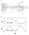
次に、本発明の一実施例に係る調整用測定工具による測定方法について、図3および図4を用いて説明をする。図3(a)は本発明の一実施例に係る調整用測定工具の測定方法(θ=0の場合)を示す模式図、図3(b)はその測定結果を示すグラフ、図4(a)は本発明の一実施例に係る調整用測定工具の測定方法(θ=βの場合)を示す模式図、図4(b)はその測定結果を示すグラフである。
まずここでは、互いに隣り合う位置に配置される搬送ローラ10・10として選択した、基準となる基準側搬送ローラ12と測定対象となる調整側搬送ローラ13について、基準側搬送ローラ12と調整側搬送ローラ13の軸心が設計上、同一水平面内に配置されている場合(即ち、θ=0の場合)の測定方法を説明する。
Next, a measurement method using the adjustment measuring tool according to one embodiment of the present invention will be described with reference to FIGS. 3 and 4. FIG. 3A is a schematic diagram showing a measuring method (when θ = 0) of the adjustment measuring tool according to one embodiment of the present invention, FIG. 3B is a graph showing the measurement result, and FIG. ) Is a schematic view showing a measuring method (when θ = β) of the measuring tool for adjustment according to one embodiment of the present invention, and FIG. 4B is a graph showing the measurement results.
First, here, the reference-
図3に示す如く、クランプ部2を基準側搬送ローラ12に相対回転不能に取り付けることにより、調整用測定工具1を基準となる基準側搬送ローラ12に固定し、調整側搬送ローラ13に対して、レーザ距離センサ4からレーザ光を照射する。
調整用測定工具1は、レーザ距離センサ4および角度センサ5を有しているため、レーザ距離センサ4から調整側搬送ローラ13までの距離と、レーザ距離センサ4から照射するレーザ光の照射角度を同時に測定することができる。
As shown in FIG. 3, the
Since the
ここで、レーザ光が調整側搬送ローラ13に対して照射可能である範囲(即ち、−α≦θ≦+αの範囲)で、基準側搬送ローラ12の軸心を中心に基準側搬送ローラ12とともに調整用測定工具1を揺動させると、レーザ距離センサ4から調整側搬送ローラ13までの距離Dと、レーザ距離センサ4から照射するレーザ光の照射角度(即ち、センサ支持軸3の水平方向に対する角度θ)を同時に測定することができる。そして、図3(b)のグラフに示すような測定データを得ることができる。
Here, the reference-
そして、この測定データのレーザ距離センサ4により測定した距離Dの最小値(Dmin)から、基準側搬送ローラ12と調整側搬送ローラ13の軸間距離Lを求めることができる。より詳しくは、基準側搬送ローラ12の軸心から照射部4aまでの距離をX、調整側搬送ローラ13のローラ半径をr1とすれば、基準側搬送ローラ12と調整側搬送ローラ13の軸間距離Lは以下の数式(1)で求めることができる。尚、基準側搬送ローラ12の軸心から照射部4aまでの距離Xは、基準側搬送ローラ12の半径r2が既知であれば、挟持部2dの形状等を考慮して予め求めておくことができる。
L=X+Dmin+r1 ・・・(1)
Then, from the minimum value (Dmin) of the distance D measured by the
L = X + Dmin + r1 (1)
そして、この求めた軸間距離Lが、ウェブ搬送装置50の軸間距離の設計値に対して予め設定した規定値以内であるか否かを確認する。軸間距離Lが軸間距離の設計値に対して予め設定した規定値以内でなければ、その軸間距離の設計値と求めた軸間距離Lとの誤差に基づいて調整側搬送ローラ13の支持状態を調整し、軸間距離Lが軸間距離の設計値に対して予め設定した規定値以内であれば、調整側搬送ローラ13の支持状態は良好であると判断し、次の測定作業に移行する。
Then, it is confirmed whether or not the obtained inter-axis distance L is within a predetermined value set in advance with respect to the design value of the inter-axis distance of the
また、図3(b)で例示した測定データでは、距離Dが最小値(Dmin)となるとき(即ち、図3(b)中の点Q1)に、角度θがθ=0となっている(即ち、図3(b)中の点P1)。仮に、調整側搬送ローラ13の異なる2箇所の部位に対する測定データのいずれもが、このような測定データ(即ち、角度θがθ=0となるときに、距離Dの測定値が最小(Dmin)となる)となるとき、調整側搬送ローラ13の軸心が、基準側搬送ローラ12の軸心と同一水平面内(即ち、θ=0となる水平面内)に正しく配置されていることが確認できる。尚、この確認に際しては、調整側搬送ローラ13の異なる2箇所の部位は、極力離れた部位(例えば、調整側搬送ローラ13の両端部)を選定することが望ましい。
In the measurement data illustrated in FIG. 3B, when the distance D is the minimum value (Dmin) (that is, the point Q1 in FIG. 3B), the angle θ is θ = 0. (That is, point P1 in FIG. 3B). Temporarily, any of the measurement data for two different parts of the adjustment-
尚、この例では、距離Dが最小値(Dmin)となるときに、角度θが正確にθ=0となっているが、必ずしも正確にθ=0となる必要はなく、予め定めた角度θの規定値以内であれば、調整側搬送ローラ13の支持状態は良好であると判断し、次の測定作業に移行する。予め定めた角度θが規定値以内でなければ、その誤差に基づいて調整側搬送ローラ13の支持状態を調整するようにしている。
In this example, when the distance D becomes the minimum value (Dmin), the angle θ is exactly θ = 0. However, it is not always necessary that θ = 0 be accurate, and a predetermined angle θ If it is within the specified value, it is determined that the support state of the adjustment-
次に、互いに隣り合う位置に配置される搬送ローラ10・10として選択した、基準となる基準側搬送ローラ12と測定対象となる調整側搬送ローラ13について、基準側搬送ローラ12と調整側搬送ローラ13の軸心が設計上、水平面に対して角度βだけ傾斜している同一平面内に配置されている場合(即ち、θ=βの場合)の測定方法を説明する。
Next, the reference-
図4に示す如く、調整用測定工具1を基準となる基準側搬送ローラ12に固定し、調整側搬送ローラ13に対して、レーザ距離センサ4からレーザ光を照射する。
As shown in FIG. 4, the
ここで、レーザ光が調整側搬送ローラ13に対して照射可能である範囲(即ち、(β−α)≦θ≦(β+α)の範囲)で、基準側搬送ローラ12の軸心を中心に基準側搬送ローラ12とともに調整用測定工具1を揺動させると、レーザ距離センサ4から調整側搬送ローラ13までの距離Dと、レーザ距離センサ4から照射するレーザ光の照射角度θを同時に測定することができる。そして、図4(b)に示すような測定データを得ることができる。
Here, the axis of the reference-
この測定データからの、前述したθ=0の場合と同様に、レーザ距離センサ4により測定した距離Dの最小値(Dmin)から、前述した数式(1)により基準側搬送ローラ12と調整側搬送ローラ13の軸間距離Lを求めることができる。
As in the case of θ = 0 described above, from the measurement data, the reference-
そして、この求めた軸間距離Lが、ウェブ搬送装置50の軸間距離の設計値に対して予め設定した規定値以内であるか否かを確認する。軸間距離Lが軸間距離の設計値に対して予め設定した規定値以内でなければ、その軸間距離の設計値と求めた軸間距離Lとの誤差に基づいて調整側搬送ローラ13の支持状態を調整し、軸間距離Lが軸間距離の設計値に対して予め設定した規定値以内であれば、調整側搬送ローラ13の支持状態は良好であると判断し、次の測定作業に移行する。
Then, it is confirmed whether or not the obtained inter-axis distance L is within a predetermined value set in advance with respect to the design value of the inter-axis distance of the
また、図4(b)で例示した測定データでは、距離Dが最小値(Dmin)となるとき(即ち、図4(b)中の点Q2)に、角度θがθ=βとなっている(即ち、図4(b)中の点P2)。仮に、調整側搬送ローラ13の異なる2箇所の部位に対する測定データのいずれもが、このような測定データ(即ち、角度θがθ=βとなるときに、距離Dの測定値が最小(Dmin)となる)となるとき、調整側搬送ローラ13の軸心が、基準側搬送ローラ12の軸心と水平面に対して角度βだけ傾斜している同一平面内に(即ち、θ=βとなる平面内)に正しく配置されていることが確認できる。尚、この確認に際しては、前述した、θ=0の場合と同様に、調整側搬送ローラ13の異なる2箇所の部位は、極力離れた部位(例えば、調整側搬送ローラ13の両端部)を選定することが望ましい。
In the measurement data illustrated in FIG. 4B, the angle θ is θ = β when the distance D is the minimum value (Dmin) (that is, the point Q2 in FIG. 4B). (That is, point P2 in FIG. 4B). Temporarily, any of the measurement data for two different parts of the adjustment-
尚、この例では、距離Dが最小値(Dmin)となるときに、角度θが正確にθ=βとなっているが、必ずしも正確にθ=βとなる必要はなく、予め定めた角度θの規定値以内であれば、調整側搬送ローラ13の支持状態は良好であると判断し、次の測定作業に移行する。予め定めた角度θが規定値以内でなければ、その誤差に基づいて調整側搬送ローラ13の支持状態を調整するようにしている。
In this example, when the distance D becomes the minimum value (Dmin), the angle θ is exactly θ = β, but it is not always necessary to be exactly θ = β, and a predetermined angle θ If it is within the specified value, it is determined that the support state of the adjustment-
このように、本発明に係る調整用測定工具1を用いれば、基準側搬送ローラ12に対する調整側搬送ローラ13の仰角(即ち、角度θ)に関わらず、調整側搬送ローラ13の平行度を容易に精度良く確認することができる。
As described above, when the
即ち、本発明に係る調整用測定工具1は、ウェブ搬送装置50を構成する複数の搬送ローラ10・10・・・の平行度を確認するために用いる搬送ローラ10・10・・・の調整用測定工具1であって、調整用測定工具1は、調整用測定工具1を前記複数の搬送ローラ10・10・・・から選択した任意の基準側搬送ローラ12に対して相対回転不能に固定するためのクランプ部2と、クランプ部2から突設するセンサ支持部3と、センサ支持部3に固設されるレーザ距離センサ4と、センサ支持部3に固設される角度センサ5と、を備え、レーザ距離センサ4により、レーザ距離センサ4から任意の基準側搬送ローラ12と隣り合う位置に配置される調整側搬送ローラ13までの距離を測定し、それと同時に、角度センサ5により、レーザ距離センサ4による測定方向の水平方向に対する角度θを測定する構成としている。
このような構成とすることにより、隣り合う位置に配置される搬送ローラ10・10の軸間距離Lと仰角(即ち、角度θ)を容易に測定することができるのである。
That is, the
With such a configuration, it is possible to easily measure the inter-axis distance L and the elevation angle (that is, the angle θ) of the
次に、本発明の一実施例に係る調整用測定工具を用いた平行度調整方法について、図5〜図9を用いて説明をする。
図5は本発明の一実施例に係る調整用測定工具を用いた調整方法を示す作業フロー図、図6は本発明の一実施例に係る調整用測定工具を用いた調整方法(準備工程)を示す模式図、図7は本発明の一実施例に係る調整用測定工具を用いた調整方法(一端側調整工程)を示す模式図、図8は本発明の一実施例に係る調整用測定工具を用いた調整方法(他端側調整工程)を示す模式図、図9は本発明の一実施例に係る調整用測定工具を用いた調整方法(移行工程)を示す模式図である。
Next, a parallelism adjustment method using the adjustment measurement tool according to one embodiment of the present invention will be described with reference to FIGS.
FIG. 5 is a work flow diagram showing an adjustment method using the adjustment measurement tool according to one embodiment of the present invention, and FIG. 6 is an adjustment method (preparation process) using the adjustment measurement tool according to one embodiment of the present invention. FIG. 7 is a schematic view showing an adjustment method (one-end side adjustment step) using the adjustment measuring tool according to one embodiment of the present invention, and FIG. 8 is an adjustment measurement according to one embodiment of the present invention. FIG. 9 is a schematic diagram showing an adjustment method (transition step) using an adjustment measuring tool according to an embodiment of the present invention.
本発明の一実施例に係る調整用測定工具を用いた平行度調整方法では、図1に示すウェブ搬送装置50を構成する各部ごと(例えば、巻出し部51、塗工部52、乾燥部53、巻取り部54等)に本発明に係る平行度調整方法を適用し、各部ごとの各搬送ローラ10・10・・・相互の平行度を確保することにより、ウェブ搬送装置50を構成する全ての搬送ローラ10・10・・・相互の平行度を確保するようにしている。尚、前記各部(例えば、巻出し部51、塗工部52、乾燥部53、巻取り部54等)の各部同士の平行度は保持されていることを前提としている。
In the parallelism adjusting method using the measuring tool for adjustment according to one embodiment of the present invention, each part constituting the
(準備工程)
図5および図6に示す如く、本発明の一実施例に係る調整用測定工具1を用いた平行度の調整方法では、まず始めに平行度の基準となる基準ローラ11を選択し、この基準ローラ11が所定の支持位置に支持されていること、および水平に支持されていることを、水平器17等を用いて作業者が目視等で確認する(Step−1)。
本実施例では、基準ローラ11として、ウェブ搬送装置50の搬送経路の最も上流側の搬送ローラ10を選定するようにしている。そして、後述するように、搬送方向上流側から下流側に向けて順次平行度を調整するようにしている。
尚、以後の説明では、図6中に示す矢印Aの方向を左方、矢印Bの方向を右方として説明を行う(図7〜図9においても、左方・右方の方向は同様とする)。
(Preparation process)
As shown in FIGS. 5 and 6, in the method for adjusting parallelism using the
In this embodiment, as the
In the following description, the direction of the arrow A shown in FIG. 6 will be described as the left direction and the direction of the arrow B as the right direction (the left and right directions are the same in FIGS. 7 to 9). To do).
(一端側調整工程)
図5および図7に示す如く、次に準備工程において選定し、支持状態を調整した基準ローラ11を、基準側搬送ローラ12とし、かつ、基準側搬送ローラ12と隣り合う位置に配置される搬送ローラ10を調整側搬送ローラ13として選定する(Step−2)。
そして、選定した基準側搬送ローラ12の左側の一端部12aに調整用測定工具1を取付ける(Step−3)。
尚、本例では、先に左側の一端部12aに調整用測定工具1を取付けるようにしているが、後述する右側の他端部12bに調整用測定工具1を先に取付けることも可能であり、先にどちらの端部に調整用測定工具1を取付けるかによって、本発明を限定するものではない。
(One end side adjustment process)
As shown in FIGS. 5 and 7, the
And the measuring
In this example, the
次に、調整用測定工具1によって、基準側搬送ローラ12の左側の一端部12aと、調整側搬送ローラ13の左側の一端部13aとの軸間距離Lおよび仰角(角度θ)を測定する(Step−4)。尚、ここでは、基準側搬送ローラ12に対して調整用測定工具1が取付けられた方向と同じ方向の調整側搬送ローラ13の端部について測定を行う必要がある。つまり、基準側搬送ローラ12に対して調整用測定工具1が左側の一端部12aに取付けられている場合には、調整側搬送ローラ13の左側の一端部13aについて測定を行い、基準側搬送ローラ12に対して調整用測定工具1が右側の他端部12bに取付けられている場合には、調整側搬送ローラ13の右側の他端部13bについて測定を行う。
Next, the
そして、この測定により得られた測定結果から平行度を確認し、測定結果に基づいて、調整側搬送ローラ13の左側の一端部13aの支持状態を調整する(Step−5)。具体的には、調整側搬送ローラ13のローラ軸13cを支持しているベアリング14と、ベアリング14を保持しているケース15との間にシム16を適宜挿入し、調整側搬送ローラ13の支持位置を調整するようにしている。
And a parallelism is confirmed from the measurement result obtained by this measurement, and the support state of the
そして、調整用測定工具1によって、基準側搬送ローラ12の左側の一端部12aと、調整側搬送ローラ13の左側の一端部13aとの軸間距離Lおよび仰角(角度θ)を再度測定し(Step−6)、この測定結果による判定を行うようにしている(Step−7)。
つまり、左側の一端部12a・13aの軸間距離Lおよび仰角(角度θ)が予め定めた規定値以内であれば、次の工程(即ち、他端側調整工程)に移行し、軸間距離Lおよび仰角(角度θ)が予め定めた規定値以内でなければ、前述した(Step−5)に戻って、再度調整側搬送ローラ13の左側の一端部13aの支持状態を調整するようにしている。このようにして、左側の一端部12a・13aの軸間距離Lおよび仰角(角度θ)が予め定めた規定値以内となるまで、繰り返し調整側搬送ローラ13の左側の一端部13aの支持状態を調整し、軸間距離Lおよび仰角(角度θ)が予め定めた規定値以内となった場合に次の工程(即ち、他端側調整工程)に移行するようにしている。
Then, the
That is, if the inter-axis distance L and the elevation angle (angle θ) of the
(他端側調整工程)
図5および図8に示す如く、次に、基準側搬送ローラ12の右側の他端部12bに調整用測定工具1を取付けて(Step−8)、調整用測定工具1によって、基準側搬送ローラ12の右側の他端部12bと、調整側搬送ローラ13の右側の他端部13bとの軸間距離Lおよび仰角(角度θ)を測定する(Step−9)。
そして、この測定により得られた測定結果から平行度を確認し、測定結果に基づいて、調整側搬送ローラ13の右側の他端部13bの支持状態を調整する(Step−10)。
(Other end side adjustment process)
Next, as shown in FIG. 5 and FIG. 8, the
And a parallelism is confirmed from the measurement result obtained by this measurement, and the support state of the
そして、調整用測定工具1によって、基準側搬送ローラ12の右側の他端部12bと、調整側搬送ローラ13の右側の他端部13bとの軸間距離Lおよび仰角(角度θ)を再度測定し(Step−11)、この測定結果による判定を行うようにしている(Step−12)。
つまり、一端側調整工程と同様に、右側の他端部12b・13bの軸間距離Lおよび仰角(角度θ)が予め定めた規定値以内であれば、次の工程(即ち、更新工程)に移行し、軸間距離Lおよび仰角(角度θ)が予め定めた規定値以内でなければ、前述した(Step−10)に戻って、再度調整側搬送ローラ13の支持状態を調整するようにしている。このようにして、軸間距離Lおよび仰角(角度θ)が予め定めた規定値以内となるまで、繰り返し調整側搬送ローラ13の右側の他端部13bの支持状態を調整し、右側の他端部12b・13bの軸間距離Lおよび仰角(角度θ)が予め定めた規定値以内となった場合に、調整側搬送ローラ13の調整を完了する(Step−13)。
Then, the
That is, similarly to the one end side adjustment step, if the inter-axis distance L and the elevation angle (angle θ) of the
次に、調整が完了した調整側搬送ローラ13の基準側搬送ローラ12とは反対側(即ち、本実施例ではウェブ9の搬送方向下流側)において隣り合う位置に配置される搬送ローラ10があるか否かを確認し(Step−14)、下流側において隣り合う位置に配置される搬送ローラ10がある場合には、次の工程(即ち、更新工程)に移行し、下流側において隣り合う位置に配置される搬送ローラ10がない場合には、調整用測定工具1を用いた一連の平行度の調整作業を完了するようにしている(Step−16)。
Next, there is a
(更新工程)
図5および図9に示す如く、調整が完了した調整側搬送ローラ13の基準側搬送ローラ12とは反対側(即ち、本実施例ではウェブ9の搬送方向下流側)において隣り合う位置に配置される搬送ローラ10がある場合には、その搬送ローラ10を調整側搬送ローラ13として更新し、今回の一端側および他端側調整工程によって支持位置の調整が完了した調整側搬送ローラ13を基準側搬送ローラ12として更新するようにしている(Step−15)。そして、前述した(Step−3)に戻って、更新した基準側搬送ローラ12を基準として、更新した調整側搬送ローラ13について、平行度の調整作業を引き続き行うようにしている。
(Update process)
As shown in FIGS. 5 and 9, the adjustment-
このように、本発明に係る調整用測定工具1を用いた平行度の調整方法では、最初に選定した基準ローラ11(即ち、本実施例ではウェブ9の搬送経路の最も上流側の搬送ローラ10)について、綿密に支持状態を調整しておけば、それ以降(即ち、本実施例では基準ローラ11よりもウェブ9の搬送方向下流側の搬送ローラ10)の搬送ローラ10の平行度の確認および調整は、調整用測定工具1によって、連鎖的に容易に精度良く行うことができる。また、調整用測定工具1の測定結果に基づいて平行度の調整を行うことにより、作業者の技量に関わらず、容易に各搬送ローラ10・10・・・相互間の平行度を調整することができる。
Thus, in the parallelism adjustment method using the
即ち、本発明に係る調整用測定工具1を用いた平行度の調整方法においては、ウェブ搬送装置50を構成する複数の搬送ローラ10の平行度を確認するために用いる調整用測定工具1を用いた搬送ローラ10の調整方法であって、調整用測定工具1は、調整用測定工具1を前記複数の搬送ローラ10から選択した任意の基準側搬送ローラ12に対して相対回転不能に固定するためのクランプ部2と、クランプ部2から突設するセンサ支持部3と、センサ支持部3に固設されるレーザ距離センサ4と、センサ支持部3に固設される角度センサ5と、を備え、クランプ部2によって、調整用測定工具1を基準側搬送ローラ12の左側(あるいは右側)の一端部12aに固定し、レーザ距離センサ4によって、レーザ距離センサ4と基準側搬送ローラ12と隣り合う位置に配置される調整側搬送ローラ13の左側(あるいは右側)の一端部13aまでの距離Dを測定して、基準側搬送ローラ12の左側(あるいは右側)の一端部12aと調整側搬送ローラ13の左側(あるいは右側)の一端部13aとの軸間距離Lを求め、それと同時に、角度センサ5によって、レーザ距離センサ4による測定方向の水平方向に対する角度θを測定し、求めた距離Dminが最短となるときの軸間距離Lが、予め設定した軸間距離Lの規定値の範囲以内であり、かつ、測定した軸間距離Lが最短となるときに測定した角度θが、予め設定した角度の規定値の範囲以内となるように調整側搬送ローラ13の左側(あるいは右側)の一端部13aの位置を調整し、次に、クランプ部2によって、調整用測定工具1を基準側搬送ローラ12の右側(あるいは左側)の他端部12bに固定し、レーザ距離センサ4によって、レーザ距離センサ4と調整側搬送ローラ13の右側(あるいは左側)の他端部13bまでの距離Dを測定して、基準側搬送ローラ12の右側(あるいは左側)の他端部12bと調整側搬送ローラ13の右側(あるいは左側)の他端部13bとの軸間距離Lを求め、それと同時に、角度センサ5によって、レーザ距離センサ4による測定方向の水平方向に対する角度θを測定し、測定した軸間距離Lが最短となるときの距離Dminが、予め設定した軸間距離Lの規定値の範囲以内であり、かつ、測定した軸間距離Lが最短となるときに測定した角度θが、予め設定した角度の規定値の範囲以内となるように調整側搬送ローラ13の右側の他端部13bの位置を調整し、調整側搬送ローラ13の調整を完了するものである。
これにより、調整用測定工具1の測定結果から基準側搬送ローラ12と調整側搬送ローラ13の平行度を容易に確認することができるのである。そして、その測定結果に基づいて、基準側搬送ローラ12と調整側搬送ローラ13の平行度(即ち、複数の搬送ローラ10・10・・・相互間の平行度)を容易に調整することができるのである。
That is, in the parallelism adjustment method using the
Thereby, the parallelism of the reference |
また、本発明に係る調整用測定工具1を用いた平行度の調整方法においては、調整側搬送ローラ13の調整が完了した後に、調整が完了した調整側搬送ローラ13の基準側搬送ローラ12とは反対側において隣り合う位置に配置される搬送ローラ10・10を調整側搬送ローラ13として更新し、かつ、調整が完了した調整側搬送ローラ13を基準側搬送ローラ12として更新するようにしている。
これにより、ウェブ搬送装置50を構成する複数の搬送ローラ10・10・・・の平行度を、作業者の技量に関わらず、容易に精度良く調整することができるのである。
Further, in the method for adjusting parallelism using the
This makes it possible to easily and accurately adjust the parallelism of the plurality of
1 調整用測定工具
2 クランプ部
2c 挟持部
2d 挟持部
3 センサ支持部
4 レーザ距離センサ
5 角度センサ
10 搬送ローラ
12 基準側搬送ローラ
13 調整側搬送ローラ
DESCRIPTION OF
Claims (11)
前記複数の搬送ローラから選択した任意の基準側搬送ローラに対して相対回転不能に固定されるクランプ部と、
該クランプ部から突設するセンサ支持部と、
該センサ支持部に固設される距離センサと、
前記センサ支持部に固設される角度センサと、
を備え、
前記距離センサにより、
該距離センサから前記任意の基準側搬送ローラと隣り合う位置に配置される調整側搬送ローラまでの距離を測定し、
前記角度センサにより、
前記距離センサによる測定方向の水平方向に対する角度を測定する、
ことを特徴とする搬送ローラの調整用測定工具。 A measuring tool for adjusting a conveying roller used for confirming the parallelism of a plurality of conveying rollers constituting a web conveying device,
A clamp portion fixed so as not to rotate relative to an arbitrary reference-side transport roller selected from the plurality of transport rollers;
A sensor support portion protruding from the clamp portion;
A distance sensor fixed to the sensor support;
An angle sensor fixed to the sensor support;
With
By the distance sensor,
Measure the distance from the distance sensor to the adjustment-side conveyance roller disposed at a position adjacent to the arbitrary reference-side conveyance roller,
By the angle sensor,
Measuring the angle of the measuring direction by the distance sensor with respect to the horizontal direction;
A measuring tool for adjusting a conveying roller.
非接触式距離センサにより構成される、
ことを特徴とする請求項1記載の搬送ローラの調整用測定工具。 The distance sensor is
Consists of a non-contact distance sensor,
The measuring tool for adjusting a conveying roller according to claim 1.
レーザ式距離センサにより構成される、
ことを特徴とする請求項2記載の搬送ローラの調整用測定工具。 The non-contact distance sensor is
Consists of a laser distance sensor,
The measuring tool for adjusting a conveying roller according to claim 2.
Vブロック状の保持部を有する、
ことを特徴とする請求項1〜請求項3のいずれか一項に記載の搬送ローラの調整用測定工具。 The clamp part is
Having a V-block holding part,
The measuring tool for adjusting a conveying roller according to any one of claims 1 to 3, wherein the measuring tool is used for adjusting the conveying roller.
伸縮可能に構成される、
ことを特徴とする請求項1〜請求項4のいずれか一項に記載の搬送ローラの調整用測定工具。 The sensor support is
Configured to be stretchable,
The measuring tool for adjusting a conveying roller according to any one of claims 1 to 4, wherein the measuring tool is used for adjusting the conveying roller.
前記調整用測定工具は、
前記複数の搬送ローラから選択した任意の基準側搬送ローラに対して相対回転不能に固定されるクランプ部と、
該クランプ部から突設するセンサ支持部と、
該センサ支持部に固設される距離センサと、
前記センサ支持部に固設される角度センサと、
を備え、
前記クランプ部を前記基準側搬送ローラの一端部に固定し、
前記距離センサによって、
該距離センサと前記基準側搬送ローラと隣り合う位置に配置される調整側搬送ローラの一端部までの距離を測定して、前記基準側搬送ローラの一端部と前記調整側搬送ローラの一端部との軸間距離を求め、
前記角度センサによって、
前記距離センサによる測定方向の水平方向に対する角度を測定し、
求めた軸間距離が最短となるときの軸間距離が、
予め設定した軸間距離の規定値の範囲以内であり、かつ、
測定した軸間距離が最短となるときに測定した角度が、
予め設定した角度の規定値の範囲以内となるように前記調整側搬送ローラの一端部の位置を調整し、
次に、
前記クランプ部を前記基準側搬送ローラの他端部に固定し、
前記距離センサによって、
該距離センサと調整側搬送ローラの他端部までの距離を測定して、前記基準側搬送ローラの他端部と前記調整側搬送ローラの他端部との軸間距離を求め、
前記角度センサによって、
前記距離センサによる測定方向の水平方向に対する角度を測定し、
測定した軸間距離が最短となるときの軸間距離が、
予め設定した軸間距離の規定値の範囲以内であり、かつ、
測定した軸間距離が最短となるときに測定した角度が、
予め設定した角度の規定値の範囲以内となるように前記調整側搬送ローラの他端部の位置を調整して、
前記調整側搬送ローラの調整を完了する、
ことを特徴とする搬送ローラの調整方法。 A method for adjusting a conveyance roller using a measurement tool for adjusting a conveyance roller used for confirming the parallelism of a plurality of conveyance rollers constituting a web conveyance device,
The adjustment measuring tool is:
A clamp portion fixed so as not to rotate relative to an arbitrary reference-side transport roller selected from the plurality of transport rollers;
A sensor support portion protruding from the clamp portion;
A distance sensor fixed to the sensor support;
An angle sensor fixed to the sensor support;
With
Fixing the clamp part to one end of the reference-side transport roller;
By the distance sensor,
Measuring the distance to one end of the adjustment-side conveyance roller disposed at a position adjacent to the distance sensor and the reference-side conveyance roller; and one end of the reference-side conveyance roller and one end of the adjustment-side conveyance roller The distance between the axes of
By the angle sensor,
Measure the angle of the measurement direction by the distance sensor with respect to the horizontal direction,
The distance between the axes when the calculated distance between the axes is the shortest.
It is within the range of the specified value of the distance between axes set in advance, and
The angle measured when the measured distance between axes is the shortest
Adjust the position of one end of the adjustment-side transport roller so that it is within the range of the preset angle value,
next,
Fixing the clamp to the other end of the reference-side transport roller;
By the distance sensor,
A distance between the distance sensor and the other end of the adjustment-side conveyance roller is measured to determine an inter-axis distance between the other end of the reference-side conveyance roller and the other end of the adjustment-side conveyance roller;
By the angle sensor,
Measure the angle of the measurement direction by the distance sensor with respect to the horizontal direction,
The distance between the axes when the measured distance between the axes is the shortest
It is within the range of the specified value of the distance between axes set in advance, and
The angle measured when the measured distance between axes is the shortest
Adjust the position of the other end of the adjustment-side transport roller so that it is within the range of the preset angle value,
Completing the adjustment of the adjustment-side conveying roller;
A method for adjusting a conveying roller, characterized in that:
調整が完了した前記調整側搬送ローラの前記基準側搬送ローラとは反対側において隣り合う位置に配置される搬送ローラを前記調整側搬送ローラとして更新し、かつ、
調整が完了した前記調整側搬送ローラを前記基準側搬送ローラとして更新する、
ことを特徴とする請求項6記載の搬送ローラの調整方法。 After the adjustment of the adjustment side conveying roller is completed,
Update the conveyance roller arranged at the position adjacent to the reference-side conveyance roller on the side opposite to the reference-side conveyance roller, the adjustment-side conveyance roller having been adjusted, and
Updating the adjustment-side conveyance roller that has been adjusted as the reference-side conveyance roller;
The method for adjusting a conveyance roller according to claim 6.
非接触式距離センサにより構成される、
ことを特徴とする請求項6または請求項7に記載の搬送ローラの調整方法。 The distance sensor is
Consists of a non-contact distance sensor,
The method for adjusting a conveyance roller according to claim 6 or 7, wherein:
レーザ式距離センサにより構成される、
ことを特徴とする請求項8記載の搬送ローラの調整方法。 The non-contact distance sensor is
Consists of a laser distance sensor,
The method for adjusting a conveying roller according to claim 8.
Vブロック状の保持部を有する、
ことを特徴とする請求項6〜請求項9のいずれか一項に記載の搬送ローラの調整方法。 The clamp part is
Having a V-block holding part,
The method for adjusting a conveyance roller according to any one of claims 6 to 9, wherein:
伸縮可能に構成される、
ことを特徴とする請求項6〜請求項10のいずれか一項に記載の搬送ローラの調整方法。 The sensor support is
Configured to be stretchable,
The method for adjusting a conveyance roller according to any one of claims 6 to 10, wherein:
Priority Applications (1)
| Application Number | Priority Date | Filing Date | Title |
|---|---|---|---|
| JP2008076490A JP4985508B2 (en) | 2008-03-24 | 2008-03-24 | Measuring tool for adjusting the conveying roller and adjusting method |
Applications Claiming Priority (1)
| Application Number | Priority Date | Filing Date | Title |
|---|---|---|---|
| JP2008076490A JP4985508B2 (en) | 2008-03-24 | 2008-03-24 | Measuring tool for adjusting the conveying roller and adjusting method |
Publications (2)
| Publication Number | Publication Date |
|---|---|
| JP2009227425A JP2009227425A (en) | 2009-10-08 |
| JP4985508B2 true JP4985508B2 (en) | 2012-07-25 |
Family
ID=41243282
Family Applications (1)
| Application Number | Title | Priority Date | Filing Date |
|---|---|---|---|
| JP2008076490A Expired - Fee Related JP4985508B2 (en) | 2008-03-24 | 2008-03-24 | Measuring tool for adjusting the conveying roller and adjusting method |
Country Status (1)
| Country | Link |
|---|---|
| JP (1) | JP4985508B2 (en) |
Families Citing this family (3)
| Publication number | Priority date | Publication date | Assignee | Title |
|---|---|---|---|---|
| JP5592670B2 (en) * | 2010-03-02 | 2014-09-17 | 富士フイルム株式会社 | Solution casting equipment and method |
| KR101784003B1 (en) | 2010-10-08 | 2017-11-06 | 엘지디스플레이 주식회사 | Apparatus for manufacturing liquid crystal display device |
| CN115636257B (en) * | 2022-10-19 | 2023-06-20 | 中建材佳星玻璃(黑龙江)有限公司 | Roller bearing bracket for glass conveying |
Family Cites Families (3)
| Publication number | Priority date | Publication date | Assignee | Title |
|---|---|---|---|---|
| JP2819341B2 (en) * | 1990-04-24 | 1998-10-30 | 武藤工業株式会社 | Rolling device for roll paper plotter, parallel adjustment method thereof, and jig thereof |
| JPH09126705A (en) * | 1995-10-31 | 1997-05-16 | Kawasaki Steel Corp | Roll parallelism measuring device of roll line |
| JP2001264025A (en) * | 2000-03-15 | 2001-09-26 | Kawasaki Steel Corp | Method and instrument for measuring distance between rolls |
-
2008
- 2008-03-24 JP JP2008076490A patent/JP4985508B2/en not_active Expired - Fee Related
Also Published As
| Publication number | Publication date |
|---|---|
| JP2009227425A (en) | 2009-10-08 |
Similar Documents
| Publication | Publication Date | Title |
|---|---|---|
| JP5776564B2 (en) | Work processing apparatus and work processing method | |
| JPH0642947A (en) | Method and device for measuring run-out or contour | |
| JP4985508B2 (en) | Measuring tool for adjusting the conveying roller and adjusting method | |
| CN110304484B (en) | Conveying system and tension adjusting unit | |
| JP7233102B2 (en) | Systems and methods for handling slender bodies in machining and verification plants | |
| CN104646451A (en) | Measuring unit | |
| JPH01249220A (en) | Strain straightening method | |
| JP2008007246A (en) | Belt adjusting device, belt adjusting method, and belt conveyance device | |
| US9000325B2 (en) | Roller mold manufacturing device and manufacturing method | |
| JP2010071778A (en) | Apparatus for measuring outer diameter of large diameter tube | |
| AU2004201631B2 (en) | Method and apparatus for centering a log | |
| JP5581703B2 (en) | Twist measuring device | |
| JP2007010336A (en) | Method and device for inspecting appearance | |
| JP2010271047A (en) | Apparatus for measuring shaft having optical type and touch probe type measuring mechanisms and shaft supporting mechanism, and method for measuring specifications and accuracy of shaft by the apparatus | |
| JP2006276398A (en) | Exposure device | |
| JP2991932B2 (en) | Steel plate flatness measurement method | |
| CN112719625A (en) | Feeding mechanism and optical fiber laser cutting device | |
| JP4594643B2 (en) | Raw wood centering processing method and raw wood centering processing apparatus | |
| JPH0720101Y2 (en) | Conveyor positioning device for round work | |
| JPH06273103A (en) | Method for measuring outside diameter of cylindrical object | |
| JP2013003117A (en) | Thickness measuring method of sheet-like material, and conveyance device of sheet-like material | |
| JP4074765B2 (en) | Tension control method and tension control device | |
| WO2010053028A1 (en) | Film thickness measuring apparatus and film forming method | |
| JP2008149583A (en) | Belt server for manufacturing pneumatic tire | |
| JP2011195251A (en) | Man conveyor handrail inspection device |
Legal Events
| Date | Code | Title | Description |
|---|---|---|---|
| A621 | Written request for application examination |
Free format text: JAPANESE INTERMEDIATE CODE: A621 Effective date: 20100708 |
|
| A977 | Report on retrieval |
Free format text: JAPANESE INTERMEDIATE CODE: A971007 Effective date: 20120319 |
|
| TRDD | Decision of grant or rejection written | ||
| A01 | Written decision to grant a patent or to grant a registration (utility model) |
Free format text: JAPANESE INTERMEDIATE CODE: A01 Effective date: 20120403 |
|
| A01 | Written decision to grant a patent or to grant a registration (utility model) |
Free format text: JAPANESE INTERMEDIATE CODE: A01 |
|
| A61 | First payment of annual fees (during grant procedure) |
Free format text: JAPANESE INTERMEDIATE CODE: A61 Effective date: 20120416 |
|
| FPAY | Renewal fee payment (event date is renewal date of database) |
Free format text: PAYMENT UNTIL: 20150511 Year of fee payment: 3 |
|
| LAPS | Cancellation because of no payment of annual fees |