JP4983236B2 - Ultrasonic bonding inspection apparatus, ultrasonic bonding inspection method, ultrasonic bonding apparatus, and ultrasonic bonding method - Google Patents
Ultrasonic bonding inspection apparatus, ultrasonic bonding inspection method, ultrasonic bonding apparatus, and ultrasonic bonding method Download PDFInfo
- Publication number
- JP4983236B2 JP4983236B2 JP2006332310A JP2006332310A JP4983236B2 JP 4983236 B2 JP4983236 B2 JP 4983236B2 JP 2006332310 A JP2006332310 A JP 2006332310A JP 2006332310 A JP2006332310 A JP 2006332310A JP 4983236 B2 JP4983236 B2 JP 4983236B2
- Authority
- JP
- Japan
- Prior art keywords
- ultrasonic bonding
- region
- workpiece
- ultrasonic
- bonding
- Prior art date
- Legal status (The legal status is an assumption and is not a legal conclusion. Google has not performed a legal analysis and makes no representation as to the accuracy of the status listed.)
- Expired - Fee Related
Links
Images


Description
本発明は、超音波接合検査装置、超音波接合検査方法、超音波接合装置、および超音波接合方法に関する。 The present invention relates to an ultrasonic bonding inspection apparatus, an ultrasonic bonding inspection method, an ultrasonic bonding apparatus, and an ultrasonic bonding method.
電気自動車およびハイブリッド電気自動車のモータ駆動用電源として、リチウムイオン電池およびニッケル水素電池などの二次電池の開発が盛んである。発電要素を外装部材内に封止した扁平形状の単電池を複数積層するとともに電気的に接続して構成される組電池では、隣接する複数の単電池の外装部材から導出される電極タブが、超音波接合法によって相互に接合されている。 Secondary batteries such as lithium ion batteries and nickel metal hydride batteries are actively developed as power sources for driving motors of electric vehicles and hybrid electric vehicles. In an assembled battery configured by stacking and electrically connecting a plurality of flat unit cells in which a power generation element is sealed in an exterior member, an electrode tab led out from the exterior member of a plurality of adjacent unit cells, They are joined together by ultrasonic joining.
超音波接合された電極タブの接合状態を検査する方法としては、相互に接合された電極タブを引き剥がす方向に所定の力を作用させ、電極タブが破断するか否かを判定することにより電極タブの接合強度を検査する方法が知られている。しかしながら、電極タブが破断するか否かを判定する機械的な検査方法では、電極タブに力を加える際の電極タブの変形および電極タブの金属疲労(荷重印加履歴)などにより、電極タブの接合強度が劣化するおそれがある。したがって、検査後の電極タブ(単電池)は破棄されなければならず、電極タブは抜き取り検査されるのが現状である。 As a method for inspecting the bonding state of the ultrasonically bonded electrode tabs, a predetermined force is applied in a direction in which the electrode tabs bonded to each other are peeled off, and it is determined whether or not the electrode tabs are broken. A method for inspecting the bonding strength of a tab is known. However, in the mechanical inspection method for determining whether or not the electrode tab breaks, the electrode tab is joined due to deformation of the electrode tab when a force is applied to the electrode tab and metal fatigue of the electrode tab (load application history). Strength may be deteriorated. Therefore, the electrode tab (single cell) after inspection must be discarded, and the electrode tab is inspected by sampling.
なお、下記の特許文献1には、超音波接合時における超音波振動の振幅を測定することにより、ワークの接合状態を代替的に検知する方法が開示されている。
本発明は、上記の問題を解決するためになされたものである。したがって、本発明の目的は、電極タブに力を加えることなく超音波接合状態を検査することができる超音波接合検査装置および超音波接合検査方法ならびにこれらを用いた超音波接合装置および超音波接合方法を提供することである。 The present invention has been made to solve the above problems. Therefore, an object of the present invention is to provide an ultrasonic bonding inspection apparatus and an ultrasonic bonding inspection method capable of inspecting an ultrasonic bonding state without applying a force to the electrode tab, and an ultrasonic bonding apparatus and an ultrasonic bonding using them. Is to provide a method.
本発明の上記目的は、下記の手段によって達成される。 The above object of the present invention is achieved by the following means.
本発明の超音波接合検査装置は、超音波接合されたワークの温度分布を測定する温度測定手段と、前記温度分布が測定されるワークの未接合領域と超音波接合領域との温度差を利用して、当該ワークの超音波接合領域を算出する算出手段と、通電により前記超音波接合領域でジュール熱を発生させる通電手段と、を有し、前記温度測定手段は、前記超音波接合領域でのジュール熱により超音波接合領域が未接合領域よりも高い温度を有しているワークの温度分布を測定することを特徴とする。
本発明の超音波接合検査装置は、超音波接合されたワークの温度分布を測定する温度測定手段と、前記温度分布が測定されるワークの未接合領域と超音波接合領域との温度差を利用して、当該ワークの超音波接合領域を算出する算出手段と、前記ワークを構成する一の部材を輻射熱により加熱する加熱手段と、を有し、前記温度測定手段は、前記一の部材からの熱伝導により超音波接合領域が未接合領域よりも高い温度を有している前記ワークの他の部材の温度分布を測定することを特徴とする。
The ultrasonic bonding inspection apparatus of the present invention uses a temperature measuring means for measuring a temperature distribution of a workpiece that has been ultrasonically bonded, and a temperature difference between an unbonded region and an ultrasonic bonding region of the workpiece on which the temperature distribution is measured. to a calculation means for calculating the ultrasonic bonding area of the work, have a, energizing means for generating Joule heat by the ultrasonic bonding region by energization, said temperature measuring means, in the ultrasonic bonding area The temperature distribution of the workpiece in which the ultrasonic bonding region has a higher temperature than the non-bonding region is measured by the Joule heat .
The ultrasonic bonding inspection apparatus of the present invention uses a temperature measuring means for measuring a temperature distribution of a workpiece that has been ultrasonically bonded, and a temperature difference between an unbonded region and an ultrasonic bonding region of the workpiece on which the temperature distribution is measured. And calculating means for calculating the ultrasonic bonding area of the workpiece, and heating means for heating one member constituting the workpiece by radiant heat, the temperature measuring means from the one member The temperature distribution of the other members of the workpiece in which the ultrasonic bonding region has a higher temperature than the unbonded region is measured by heat conduction.
本発明の超音波接合検査方法は、通電により、超音波接合されたワークの超音波接合領域でジュール熱を発生させる段階と、前記ワークの温度分布を測定する段階と、前記温度分布が測定されるワークの未接合領域と超音波接合領域との温度差を利用して、当該ワークの超音波接合領域を算出する段階と、を有し、前記温度分布を測定する段階において、前記超音波接合領域でのジュール熱により超音波接合領域が未接合領域よりも高い温度を有しているワークの温度分布が測定されることを特徴とする。
本発明の超音波接合検査方法は、超音波接合されたワークを構成する一の部材を輻射熱により加熱する段階と、前記ワークの温度分布を測定する段階と、前記温度分布が測定されるワークの未接合領域と超音波接合領域との温度差を利用して、当該ワークの超音波接合領域を算出する段階と、を有し、前記温度分布を測定する段階において、前記一の部材からの熱伝導により超音波接合領域が未接合領域よりも高い温度を有している前記ワークの他の部材の温度分布が測定されることを特徴とする。
In the ultrasonic bonding inspection method of the present invention, the step of generating Joule heat in the ultrasonic bonding region of the ultrasonically bonded workpiece by energization, the step of measuring the temperature distribution of the workpiece, and the temperature distribution are measured. that by utilizing a temperature difference between the non-bonded area and the ultrasonic bonding area of the work, possess calculating a ultrasonic bonding region of the workpiece, and in the step of measuring the temperature distribution, the ultrasonic bonding The temperature distribution of the workpiece in which the ultrasonic bonding region has a higher temperature than the unbonded region is measured by Joule heat in the region .
The ultrasonic bonding inspection method of the present invention includes a step of heating one member constituting an ultrasonic bonded workpiece by radiant heat, a step of measuring a temperature distribution of the workpiece, and a workpiece of which the temperature distribution is measured. Calculating the ultrasonic bonding area of the workpiece using a temperature difference between the unbonded area and the ultrasonic bonding area, and in the step of measuring the temperature distribution, heat from the one member The temperature distribution of the other members of the workpiece in which the ultrasonic bonding region has a higher temperature than the unbonded region is measured by conduction.
本発明の超音波接合装置は、接合条件にしたがってワークを超音波接合する超音波接合手段と、上記の超音波接合検査装置と、前記超音波接合検査装置により算出される超音波接合領域に基づいて、次のワークを超音波接合する際の接合条件を制御する制御手段と、を有することを特徴とする。 The ultrasonic bonding apparatus of the present invention is based on ultrasonic bonding means for ultrasonic bonding of workpieces according to bonding conditions, the ultrasonic bonding inspection apparatus, and an ultrasonic bonding area calculated by the ultrasonic bonding inspection apparatus. And a control means for controlling a joining condition when the next workpiece is ultrasonically joined.
本発明の超音波接合方法は、上記の超音波接合検査方法により算出される超音波接合領域に基づいて、次のワークを超音波接合する際の接合条件を制御することを特徴とする。 Ultrasonic bonding method of the present invention, based on the ultrasonic bonding area which is calculated by the ultrasonic bonding inspection method, characterized that you control the bonding conditions for ultrasonic bonding to the next work.
本発明の超音波接合検査装置および超音波接合検査方法によれば、超音波接合されたワークの温度分布から当該ワークの超音波接合領域を算出することができるため、ワークに力を加えることなく、接合状態を検査することができる。したがって、検査後のワークを破棄する必要がなく、全てのワークの接合状態を検査することができる。 According to the ultrasonic bonding inspection apparatus and the ultrasonic bonding inspection method of the present invention, since the ultrasonic bonding region of the workpiece can be calculated from the temperature distribution of the ultrasonic bonded workpiece, the force is not applied to the workpiece. The bonding state can be inspected. Therefore, it is not necessary to discard the workpiece after the inspection, and the joining state of all the workpieces can be inspected.
また、本発明の超音波接合装置および超音波接合方法によれば、超音波接合されたワークの温度分布から当該ワークの超音波接合領域を算出することができるため、上記の効果に加えて、ワークの検査結果を接合条件にフィードバックすることができる。したがって、最適な接合条件での超音波接合を維持することができる。 In addition, according to the ultrasonic bonding apparatus and the ultrasonic bonding method of the present invention, since the ultrasonic bonding region of the workpiece can be calculated from the temperature distribution of the ultrasonic bonded workpiece, in addition to the above effects, The inspection result of the workpiece can be fed back to the joining condition. Therefore, ultrasonic bonding under optimum bonding conditions can be maintained.
以下、添付の図面を参照して本発明の実施の形態を詳細に説明する。なお、図中、同様の部材には同一の符号を用いた。 Hereinafter, embodiments of the present invention will be described in detail with reference to the accompanying drawings. In addition, the same code | symbol was used for the same member in the figure.
(第1の実施の形態)
図1は、本発明の第1の実施の形態における超音波接合検査装置の概略構成を示す図である。図1に示されるとおり、本実施の形態の超音波接合検査装置100は、サーモカメラ200および処理部300を備える。
(First embodiment)
FIG. 1 is a diagram showing a schematic configuration of an ultrasonic bonding inspection apparatus according to the first embodiment of the present invention. As shown in FIG. 1, the ultrasonic
サーモカメラ200は、温度測定手段として、超音波接合された電極タブ900の温度分布を測定するものである。サーモカメラ200は、超音波接合された一対の電極タブ900のうち下側電極タブ900bに対向するように配置され、電極タブ900の温度分布を撮像する。サーモカメラ自体は一般的なサーモカメラであるため、詳細な説明は省略する。また、サーモカメラ200で取得された画像情報は、処理部300に送信される。
The
処理部300は、測定される電極タブ900の温度分布に基づいて、電極タブ900の超音波接合領域を算出するものである。処理部300は、サーモカメラ200から送信される画像情報を受信して、画像情報における所定温度以上の画素数を計算することにより、電極タブ900における超音波接合領域の面積を算出する。処理部300は、たとえば、一般的なコンピュータである。
The
次に、図2を参照して、本実施の形態の処理部300について詳細に説明する。図2は、本実施の形態における処理部300の概略構成を示すブロック図である。図2に示されるとおり、本実施の形態の処理部300は、CPU310、RAM320、ROM330、ハードディスク340、入力部350、表示部360、およびインタフェース370を有する。これらの各部は、バスを介して相互に接続されている。
Next, the
CPU310は、サーモカメラ200で取得される画像情報に対して種々の演算を実行するものである。CPU310は、算出部(算出手段)、第1判定部(第1の判定手段)、および判断部(判断手段)として機能する。
The
ここで、算出部は、画像情報における所定温度以上の画素数を計算することにより、超音波接合領域の面積を算出するものである。第1判定部は、算出される超音波接合領域の面積が下限値未満か否かを判定するものである。判断部は、超音波接合領域の面積が下限値未満の場合、電極タブが接合不良であると判断するものである。なお、各部の具体的な処理内容については、後述する。 Here, the calculation unit calculates the area of the ultrasonic bonding region by calculating the number of pixels equal to or higher than a predetermined temperature in the image information. The first determination unit determines whether or not the calculated area of the ultrasonic bonding region is less than a lower limit value. The determination unit determines that the electrode tab is poorly bonded when the area of the ultrasonic bonding region is less than the lower limit value. The specific processing contents of each unit will be described later.
RAM320は、上述した画像情報を一時的に記憶するものであり、ROM330は、制御プログラムおよびパラメータなどを予め記憶するものである。
The
ハードディスク340は、複数の電極タブに対してそれぞれ算出される超音波接合領域の面積を、対応する電極タブの接合情報とともに記憶する記憶手段として機能する。また、ハードディスク340は、画像情報における所定温度以上の画素数を計算することにより、超音波接合領域の面積を算出する算出プログラム、算出される超音波接合領域の面積が下限値未満か否かを判定する判定プログラム、および超音波接合領域の面積が下限値未満の場合、電極タブが接合不良であると判断する判断プログラムを格納する。
The
入力部350は、たとえば、キーボード、タッチパネル、およびマウスなどのポインティングデバイスであり、表示部360は、たとえば、液晶ディスプレイおよびCRTディスプレイなどである。
The
インタフェース370は、サーモカメラ200から送信される画像信号を受信する。
The
以上のとおり、構成される本実施の形態における超音波接合検査装置では、超音波接合された電極タブの温度分布が測定され、測定される電極タブの温度分布に基づいて、当該電極タブの超音波接合領域の面積が算出される。そして、算出される超音波接合領域の面積に基づいて、電極タブの超音波接合の良否が判断される。以下、本実施の形態における超音波接合検査方法について詳細に説明する。 As described above, in the ultrasonic bonding inspection apparatus according to the present embodiment configured, the temperature distribution of the electrode tab subjected to ultrasonic bonding is measured, and the ultrasonic distribution of the electrode tab is determined based on the temperature distribution of the electrode tab to be measured. The area of the sonic bonding region is calculated. Then, the quality of the ultrasonic bonding of the electrode tab is determined based on the calculated area of the ultrasonic bonding region. Hereinafter, the ultrasonic bonding inspection method in the present embodiment will be described in detail.
図3は、本実施の形態の超音波接合検査方法を示すフローチャートである。本実施の形態では、超音波接合時の摩擦熱により発熱している超音波接合直後の電極タブの温度分布が測定され、測定結果に基づいて超音波接合の良否が判断される。より具体的には、超音波接合直後の超音波接合領域は未接合領域よりも高い温度を有しており、サーモカメラにより超音波接合領域に対応する高温領域の面積が算出され、当該面積から超音波接合の接合強度が十分か否か、すなわち、超音波接合の良否が判断される。 FIG. 3 is a flowchart showing the ultrasonic bonding inspection method of the present embodiment. In the present embodiment, the temperature distribution of the electrode tab immediately after the ultrasonic bonding that generates heat due to the frictional heat during the ultrasonic bonding is measured, and the quality of the ultrasonic bonding is determined based on the measurement result. More specifically, the ultrasonic bonding region immediately after ultrasonic bonding has a higher temperature than the unbonded region, and the area of the high temperature region corresponding to the ultrasonic bonding region is calculated by the thermo camera, It is determined whether or not the bonding strength of the ultrasonic bonding is sufficient, that is, whether or not the ultrasonic bonding is good.
図3に示されるとおり、本実施の形態の超音波接合検査方法では、まず、超音波接合が終了したか否かが判断される(ステップS101)。超音波接合が終了していない場合(ステップS101:NO)、超音波接合が終了するまで待機する。一方、超音波接合が終了した場合(ステップS101:YES)、超音波接合の終了時点から所定時間が経過したか否かが判断される(ステップS102)。 As shown in FIG. 3, in the ultrasonic bonding inspection method according to the present embodiment, first, it is determined whether or not the ultrasonic bonding is completed (step S101). When the ultrasonic bonding is not completed (step S101: NO), the process waits until the ultrasonic bonding is completed. On the other hand, when the ultrasonic bonding is completed (step S101: YES), it is determined whether or not a predetermined time has elapsed from the end of the ultrasonic bonding (step S102).
所定時間が経過していない場合(ステップS102:NO)、所定時間が経過するまで待機する。一方、所定時間が経過した場合(ステップS102:YES)、電極タブの温度分布をサーモカメラにて撮像し、画像情報が取得される(ステップS103)。上述したとおり、超音波接合直後の電極タブは、超音波接合時の摩擦熱により超音波接合領域が未接合領域よりも高い温度を有している。 If the predetermined time has not elapsed (step S102: NO), the process waits until the predetermined time elapses. On the other hand, when the predetermined time has elapsed (step S102: YES), the temperature distribution of the electrode tab is imaged by the thermo camera, and image information is acquired (step S103). As described above, the electrode tab immediately after ultrasonic bonding has a higher temperature in the ultrasonic bonding region than in the non-bonded region due to frictional heat during ultrasonic bonding.
ここで、図4(A)は、本実施の形態における電極タブの超音波接合を説明するための図である。図4(A)に示されるとおり、本実施の形態では、重ね合わされた一組の電極タブ900がホーン710とアンビル720とにより挟み込まれ、所定の加圧力を与えられながら、ホーン710が超音波振動により往復直線運動することで、電極タブ900が超音波接合される。より具体的には、本実施の形態のホーン710およびアンビル720はそれぞれ複数の突起部711,721を有しており、突起部711,721に対応する電極タブ900の領域が超音波接合される。
Here, FIG. 4A is a view for explaining ultrasonic bonding of the electrode tab in the present embodiment. As shown in FIG. 4A, in the present embodiment, a pair of electrode tabs 900 that are overlapped are sandwiched between a
図4(B)は、サーモカメラによって測定される電極タブの温度分布のサーモグラフィを示す図である。図4(B)に示されるとおり、本実施の形態の超音波接合直後の電極タブは、複数の突起部に対応する超音波接合領域(図の黒色部分)910が未接合領域920よりも高い温度を有している。なお、超音波接合される上側電極タブ900aと下側電極タブ900bとの間に油などが介在して電極タブ900が摩擦されない場合には、図4(B)に示す図とは異なり、全体的に温度が低い画像情報が得られる。
FIG. 4B is a diagram showing a thermography of the temperature distribution of the electrode tab measured by the thermo camera. As shown in FIG. 4B, in the electrode tab immediately after ultrasonic bonding of the present embodiment, the ultrasonic bonding region (black portion in the drawing) 910 corresponding to the plurality of protrusions is higher than the
次に、画像情報における所定温度以上の画素数が計算され(ステップS104)、画像情報が格納される(ステップS105)。本実施の形態では、未接合領域よりも温度の高い超音波接合領域の面積が算出されるように所定温度が設定され、当該温度以上の画素数が計算されることにより、超音波接合領域の面積が算出される。また、画素数が算出された画像情報は、別途に入力される接合情報とともにハードディスク340に格納される。なお、接合情報とは、画像情報が取得された電極タブの表面粗さ、超音波接合時の接合条件、および超音波接合時の環境(たとえば、湿度)などである。
Next, the number of pixels equal to or higher than a predetermined temperature in the image information is calculated (step S104), and the image information is stored (step S105). In the present embodiment, the predetermined temperature is set so that the area of the ultrasonic bonding region having a temperature higher than that of the unbonded region is calculated, and the number of pixels equal to or higher than the temperature is calculated. The area is calculated. Further, the image information for which the number of pixels is calculated is stored in the
次に、算出された画素数が下限値未満か否かが判断される(ステップS106)。言い換えれば、電極タブの超音波接合領域の面積が、必要な接合強度に対応する下限面積未満か否かが判断される。本実施の形態では、予め測定される超音波接合が良好な電極タブの温度分布に基づいて、上記の下限値が設定される。算出された画素数が下限値未満の場合(ステップS106:YES)、接合強度不足、すなわち超音波接合が不良であると判断され(ステップS107)、処理が終了される。なお、判断結果は、たとえば、表示部360に表示される。
Next, it is determined whether or not the calculated number of pixels is less than a lower limit value (step S106). In other words, it is determined whether or not the area of the ultrasonic bonding region of the electrode tab is less than the lower limit area corresponding to the required bonding strength. In the present embodiment, the lower limit is set based on the temperature distribution of the electrode tab that is measured in advance and has good ultrasonic bonding. When the calculated number of pixels is less than the lower limit value (step S106: YES), it is determined that the bonding strength is insufficient, that is, ultrasonic bonding is defective (step S107), and the process is terminated. The determination result is displayed on the
一方、算出された画素数が下限値以上の場合(ステップS106:NO)、当該画素数が上限値以下か否かが判断される(ステップS108)。ここで、電極タブに必要以上に大きな摩擦力がかる場合、超音波接合領域に対応する高温領域が大きくなる一方で、電極タブが劣化してしまうおそれがある。したがって、本実施の形態では、接合強度を判定するための下限値(下限面積)に加えて、電極タブの劣化を判定するための上限値(上限面積)が設定されることが好ましい。 On the other hand, if the calculated number of pixels is equal to or greater than the lower limit (step S106: NO), it is determined whether or not the number of pixels is equal to or less than the upper limit (step S108). Here, when an excessively large frictional force is applied to the electrode tab, the high temperature region corresponding to the ultrasonic bonding region becomes large, and the electrode tab may be deteriorated. Therefore, in the present embodiment, it is preferable to set an upper limit value (upper limit area) for determining deterioration of the electrode tab in addition to a lower limit value (lower limit area) for determining the bonding strength.
算出された画素数が上限値以上の場合(ステップS108:YES)、超音波接合が不良であると判断され(ステップS107)、処理が終了される。一方、算出された画素数が上限値未満の場合(ステップS108:NO)、超音波接合が良好であると判断され(ステップS109)、処理が終了される。 If the calculated number of pixels is equal to or greater than the upper limit (step S108: YES), it is determined that the ultrasonic bonding is defective (step S107), and the process is terminated. On the other hand, when the calculated number of pixels is less than the upper limit value (step S108: NO), it is determined that the ultrasonic bonding is good (step S109), and the process ends.
以上のとおり、図3に示すフローチャートの処理によれば、超音波接合直後の電極タブの超音波接合領域と未接合領域との温度差を利用して、電極タブにおける超音波接合領域の面積が算出される。そして、算出される面積に基づいて、電極タブの接合強度、すなわち超音波接合の良否が判断される。より具体的には、超音波接合領域の面積が上限値以上および下限値未満の場合、超音波接合が不良であると判断される。 As described above, according to the processing of the flowchart shown in FIG. 3, the area of the ultrasonic bonding region in the electrode tab is determined using the temperature difference between the ultrasonic bonding region and the non-bonded region of the electrode tab immediately after ultrasonic bonding. Calculated. Then, based on the calculated area, the bonding strength of the electrode tab, that is, the quality of ultrasonic bonding is determined. More specifically, when the area of the ultrasonic bonding region is not less than the upper limit value and less than the lower limit value, it is determined that the ultrasonic bonding is defective.
なお、本実施の形態の超音波接合検査装置では、電極タブにおける超音波接合領域の面積を算出した。しかしながら、画像情報から超音波接合領域の分布形状(分布状況)を算出することもできる。このような構成にすれば、超音波接合の接合強度のみならず、電極タブの所望の領域が均一に超音波接合されているか否かを判断することができる。その結果、電極タブの接合品質がより向上される。 In the ultrasonic bonding inspection apparatus of the present embodiment, the area of the ultrasonic bonding region in the electrode tab was calculated. However, the distribution shape (distribution status) of the ultrasonic bonding region can also be calculated from the image information. With such a configuration, it is possible to determine not only the bonding strength of ultrasonic bonding but also whether a desired region of the electrode tab is uniformly ultrasonic bonded. As a result, the bonding quality of the electrode tab is further improved.
また、本実施の形態では、所定温度以上の画素数を計算することにより超音波接合領域の面積を算出した。しかしながら、所定温度未満の画素数を計算して未接合領域を計算し、全体の面積からの差分を求めることにより、超音波接合領域の面積を算出することもできる。 In the present embodiment, the area of the ultrasonic bonding region is calculated by calculating the number of pixels equal to or higher than a predetermined temperature. However, it is also possible to calculate the area of the ultrasonic bonding region by calculating the number of pixels below a predetermined temperature to calculate the unbonded region and obtaining the difference from the entire area.
以上のとおり、説明された本実施の形態は、以下の効果を奏する。 As described above, the described embodiment has the following effects.
本実施の形態の超音波接合検査装置は、超音波接合された電極タブの温度分布を測定するサーモカメラと、温度分布が測定される電極タブの未接合領域と超音波接合領域との温度差を利用して、当該電極タブの超音波接合領域を算出する算出部と、を有する。したがって、超音波接合された電極タブの温度分布から当該電極タブの超音波接合領域を算出することができるため、電極タブに力を加えることなく、接合状態を検査することができる。その結果、全ての電極タブの接合状態を検査することができる。 The ultrasonic bonding inspection apparatus according to the present embodiment includes a thermo camera that measures the temperature distribution of an electrode tab that has been ultrasonically bonded, and a temperature difference between an unbonded region and an ultrasonic bonding region of the electrode tab in which the temperature distribution is measured. And a calculation unit for calculating an ultrasonic bonding region of the electrode tab. Therefore, since the ultrasonic bonding region of the electrode tab can be calculated from the temperature distribution of the electrode tab subjected to ultrasonic bonding, the bonding state can be inspected without applying a force to the electrode tab. As a result, the bonding state of all electrode tabs can be inspected.
また、超音波接合領域の面積が直接的に算出されるため、ホーンの振動状態をモニタするといった間接的な接合強度判定方法と比較して、誤差要因が少ない。さらに、ホーンの振動状態は接合時の摩擦熱および装置の発熱などに振動状態が変化し易いことと比較して、本実施の形態の超音波接合装置は、温度をモニタするため簡単に補正することが可能である。 Further, since the area of the ultrasonic bonding region is directly calculated, there are fewer error factors than in an indirect bonding strength determination method of monitoring the vibration state of the horn. Furthermore, the vibration state of the horn is easily corrected to monitor the temperature, compared with the fact that the vibration state easily changes due to frictional heat at the time of joining and heat generation of the device. It is possible.
算出部は、サーモカメラによって取得される画像情報、電極タブの超音波接合領域を算出する。したがって、電極タブの温度分布から、電極タブにおける超音波接合領域の大きさおよび分布形状などを算出することができる。 The calculation unit calculates image information acquired by the thermo camera and an ultrasonic bonding region of the electrode tab. Therefore, the size and distribution shape of the ultrasonic bonding region in the electrode tab can be calculated from the temperature distribution of the electrode tab.
算出部は、画像情報における所定温度以上の画素数を計算することにより、超音波接合領域の大きさを算出する。したがって、超音波接合領域の面積を容易に算出することができる。 The calculation unit calculates the size of the ultrasonic bonding region by calculating the number of pixels equal to or higher than a predetermined temperature in the image information. Therefore, the area of the ultrasonic bonding region can be easily calculated.
本実施の形態の超音波接合検査装置は、超音波接合領域の面積が下限値未満か否かを判定する第1判定部と、超音波接合領域の面積が下限値未満の場合、電極タブが接合不良であると判断する判断部と、をさらに有する。したがって、超音波接合領域の面積から超音波接合の強度が判定され、超音波接合の良否を判断することができる。 The ultrasonic bonding inspection apparatus according to the present embodiment includes a first determination unit that determines whether or not the area of the ultrasonic bonding region is less than the lower limit value, and the electrode tab when the area of the ultrasonic bonding region is lower than the lower limit value. And a determination unit that determines that the bonding is defective. Therefore, the strength of ultrasonic bonding is determined from the area of the ultrasonic bonding region, and the quality of ultrasonic bonding can be determined.
サーモカメラは、超音波接合時の摩擦熱により超音波接合領域が未接合領域よりも高い温度を有している超音波接合直後の電極タブの温度分布を測定する。したがって、外部からエネルギーを加えることなく、電極タブの温度分布を測定することができる。 The thermo camera measures the temperature distribution of the electrode tab immediately after ultrasonic bonding in which the ultrasonic bonding region has a higher temperature than the unbonded region due to frictional heat during ultrasonic bonding. Therefore, the temperature distribution of the electrode tab can be measured without applying energy from the outside.
本実施の形態の超音波接合検査装置は、複数の電極タブに対してそれぞれ算出される超音波接合領域を、対応する電極タブの接合情報とともに記憶する記憶部をさらに有する。したがって、検査結果を累積することができ、超音波接合結果を統計処理して傾向を把握することができる。また、材料のロッド変化および他の誤差要因の変化に対して、検査結果を超音波接合にフィードバックすることができる。 The ultrasonic bonding inspection apparatus according to the present embodiment further includes a storage unit that stores ultrasonic bonding regions calculated for a plurality of electrode tabs together with bonding information of corresponding electrode tabs. Accordingly, the inspection results can be accumulated, and the trend can be grasped by statistically processing the ultrasonic bonding results. In addition, the inspection result can be fed back to the ultrasonic bonding in response to a change in the material rod and other error factors.
本実施の形態の超音波接合検査方法は、超音波接合された電極タブの温度分布を測定する段階と、温度分布が測定される電極タブの未接合領域と超音波接合領域との温度差を利用して、当該電極タブの超音波接合領域を算出する段階と、を有する。したがって、超音波接合された電極タブの温度分布から当該電極タブの超音波接合領域を算出することができるため、電極タブに力を加えることなく、接合状態を検査することができる。したがって、全ての電極タブの接合状態を検査することができる。 In the ultrasonic bonding inspection method of the present embodiment, a temperature distribution of an ultrasonically bonded electrode tab is measured, and a temperature difference between an unbonded area and an ultrasonic bonded area of the electrode tab where the temperature distribution is measured is calculated. And utilizing the step of calculating an ultrasonic bonding region of the electrode tab. Therefore, since the ultrasonic bonding region of the electrode tab can be calculated from the temperature distribution of the electrode tab subjected to ultrasonic bonding, the bonding state can be inspected without applying a force to the electrode tab. Therefore, the bonding state of all the electrode tabs can be inspected.
(第2の実施の形態)
第1の実施の形態では、超音波接合時の摩擦により発熱した超音波接合直後の電極タブの温度分布を測定する場合について述べた。本実施の形態では、超音波接合済みの常温状態の電極タブに外部からエネルギーを加えることにより電極タブを発熱させ、発熱させた電極タブの温度分布を測定する場合について述べる。
(Second Embodiment)
In the first embodiment, the case of measuring the temperature distribution of the electrode tab immediately after ultrasonic bonding that generates heat due to friction during ultrasonic bonding has been described. In the present embodiment, a case where the electrode tab is heated by applying energy from the outside to the electrode tab at room temperature after ultrasonic bonding and the temperature distribution of the heated electrode tab is measured will be described.
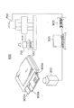
図5(A)は、本発明の第2の実施の形態における超音波接合検査装置の概略構成を示す図である。図5(A)に示されるとおり、本実施の形態の超音波接合検査装置100は、サーモカメラ200、処理部300、および電源400を備える。電源400を除いては、サーモカメラ200および処理部300は、第1の実施の形態の場合と同様であるため、説明は省略する。
FIG. 5A is a diagram showing a schematic configuration of an ultrasonic bonding inspection apparatus according to the second embodiment of the present invention. As shown in FIG. 5A, the ultrasonic
電源400は、通電手段として、通電により電極タブ900でジュール熱を発生させるものである。電源400は、超音波接合されている一対の電極タブ900を構成する上側電極タブ900aおよび下側電極タブ900bにそれぞれ接続され、電極タブ900に電圧を印加する。また、電源400は、処理部300に電気的に接続されていて、処理部300からの指令に応じて、電圧を印加することができる。
The
以上のとおり構成される本実施の形態の超音波接合検査装置100によれば、まず、処理部300からの指令に基づいて電源400が電極タブ900に電圧を印加することにより、上側電極タブ900aと下側電極タブ900bとが固相接合されている超音波接合領域910に電流が流れ、超音波接合領域910でジュール熱が発生する(図5(B)参照)。超音波接合領域910で発生するジュール熱により超音波接合領域910が未接合領域よりも高い温度を有している電極タブ900の温度分布がサーモカメラにより測定され、測定結果に基づいて、超音波接合の良否が判断される。
According to the ultrasonic
なお、超音波接合領域910でジュール熱が発生する状態が長時間続く場合、電極タブ900全体がほぼ同一の温度になってしまうため、超音波接合領域910を算出することができない。したがって、通電から所定時間経過後の電極タブ900の温度分布を測定する。また、通電により電極タブ900が加熱されることを除いては、第1の実施の形態と同様であるため、本実施の形態の超音波接合方法についての詳細な説明は省略する。
In addition, when the state which generate | occur | produces a Joule heat in the ultrasonic joining area |
以上のとおり、説明された本実施の形態は、第1の実施の形態における効果に加えて、以下の効果を奏する。 As described above, the present embodiment described has the following effects in addition to the effects of the first embodiment.
本実施の形態の超音波接合検査装置は、通電により超音波接合領域でジュール熱を発生させる電源をさらに有し、サーモカメラは、超音波接合領域でのジュール熱により超音波接合領域が未接合領域よりも高い温度を有している電極タブの温度分布を測定する。したがって、超音波接合直後の電極タブに限定されず、自由なタイミングで電極タブの温度分布が測定され、超音波接合領域を算出することができる。 The ultrasonic bonding inspection apparatus according to the present embodiment further includes a power source that generates Joule heat in the ultrasonic bonding region by energization, and the thermo camera has not joined the ultrasonic bonding region due to Joule heat in the ultrasonic bonding region. The temperature distribution of the electrode tab having a higher temperature than the region is measured. Therefore, the temperature distribution of the electrode tab is not limited to the electrode tab immediately after ultrasonic bonding, and the temperature distribution of the electrode tab can be measured at any timing, and the ultrasonic bonding region can be calculated.
(第3の実施の形態)
本実施の形態は、超音波接合済みの常温状態の電極タブに輻射熱を加えることにより、電極タブを発熱させ、発熱させた電極タブの温度分布を測定する実施の形態である。
(Third embodiment)
In the present embodiment, the electrode tab is heated by applying radiant heat to the electrode tab in a room temperature state that has been ultrasonically bonded, and the temperature distribution of the heated electrode tab is measured.
図6(A)は、本発明の第3の実施の形態における超音波接合検査装置の概略構成を示す図である。図6(A)に示されるとおり、本実施の形態の超音波接合検査装置100は、サーモカメラ200、処理部300、およびヒータ500を備える。ヒータ500を除いては、サーモカメラ200および処理部300は、第1の実施の形態の場合と同様であるため、説明は省略する。
FIG. 6A is a diagram showing a schematic configuration of an ultrasonic bonding inspection apparatus according to the third embodiment of the present invention. As shown in FIG. 6A, the ultrasonic
ヒータ500は、加熱手段として、超音波接合される一対の電極タブ900のうち上側電極タブ900aを輻射熱により加熱するものである。ヒータ500は、電極タブ900を基準としてサーモカメラ200の反対側に配置され、サーモカメラ200と対向する下側電極タブ900bと接合されている上側電極タブ900aに輻射熱を供給する。また、ヒータ500は、処理部300に電気的に接続されていて、処理部300からの指令に応じて、輻射熱を供給することができる。
The
以上のとおり構成される本実施の形態の超音波接合検査装置100によれば、まず、処理部300からの指令に基づいてヒータ500が電極タブ900に輻射熱を供給することにより、当該ヒータ500に対向する上側電極タブ900aが加熱される。上側電極タブ900aが加熱される場合、上側電極タブ900aと下側電極タブ900bとが固相接合されている超音波接合領域910は、上側電極タブ900aと下側電極タブ900bとの間に空気層が介在する未接合領域よりも短時間で熱が伝達される。したがって、上側電極タブ900aが加熱される場合、上側電極タブ900aからの熱伝導により下側電極タブ900bの超音波接合領域910が未接合領域よりも高い温度を有する(図6(B)参照)。超音波接合領域910が未接合領域よりも高い温度を有している下側電極タブ900bの温度分布がサーモカメラにより測定され、測定結果に基づいて、超音波接合の良否が判断される。
According to the ultrasonic
なお、上側電極タブ900aに輻射熱が長時間供給される場合、電極タブ900全体がほぼ同一の温度になってしまうため、超音波接合領域910を算出することができない。したがって、輻射開始から所定時間経過後の電極タブ900の温度分布を測定する。また、輻射熱により電極タブ900が加熱されることを除いては、第1の実施の形態と同様であるため、本実施の形態の超音波接合方法についての詳細な説明は省略する。
Note that, when radiant heat is supplied to the
以上のとおり、説明された本実施の形態は、第1および第2の実施の形態における効果に加えて、以下の効果を奏する。 As described above, the present embodiment described has the following effects in addition to the effects of the first and second embodiments.
本実施の形態の超音波接合検査装置は、電極タブを構成する上側電極タブを輻射熱により加熱するヒータをさらに有し、サーモカメラは、上側電極タブからの熱伝導により超音波接合領域が未接合領域よりも高い温度を有している下側電極タブの温度分布を測定する。したがって、超音波接合直後の電極タブに限定されず、自由なタイミングで電極タブの温度分布が測定され、超音波接合領域を算出することができる。さらに、大掛かりな設備を必要としない。 The ultrasonic bonding inspection apparatus of the present embodiment further includes a heater that heats the upper electrode tab constituting the electrode tab by radiant heat, and the thermo camera has an ultrasonic bonding region that is not bonded due to heat conduction from the upper electrode tab. The temperature distribution of the lower electrode tab having a higher temperature than the region is measured. Therefore, the temperature distribution of the electrode tab is not limited to the electrode tab immediately after ultrasonic bonding, and the temperature distribution of the electrode tab can be measured at any timing, and the ultrasonic bonding region can be calculated. Furthermore, no large-scale equipment is required.
(第4の実施の形態)
本実施の形態は、上記第1〜第3の実施の形態の超音波接合検査装置が組み込まれた超音波接合装置の実施の形態である。
(Fourth embodiment)
This embodiment is an embodiment of an ultrasonic bonding apparatus in which the ultrasonic bonding inspection apparatus of the first to third embodiments is incorporated.
図7は、本発明の第4の実施の形態における超音波接合装置の概略構成を示す図である。図7に示されるとおり、本実施の形態の超音波接合装置600は、サーモカメラ200、処理部300、超音波接合部700、および制御部800を備える。超音波接合部700および制御部800を除いては、サーモカメラ200および処理部300は、第1の実施の形態の場合と同様であるため、説明は省略する。
FIG. 7 is a diagram showing a schematic configuration of an ultrasonic bonding apparatus according to the fourth embodiment of the present invention. As shown in FIG. 7, the
超音波接合部700は、超音波接合手段として、接合条件にしたがって電極タブ900を超音波接合するものである。超音波接合部700は、重ね合わされた一組の電極タブ900に超音波振動を加えることにより電極タブ900を超音波接合する。また、超音波接合部700は、超音波振動で往復直線運動されつつ電極タブ900を加圧するホーン710と、ホーン710によって加圧される電極タブを支持するアンビル720とを有する。また、本実施の形態において、ホーン710およびアンビル720は、それぞれ複数の突起部711,721を備える。
The
制御部800は、超音波接合部700を制御するものである。本実施の形態において、制御部800は、処理部300で算出される超音波接合領域に基づいて、次の電極タブを超音波接合する際の接合条件を制御する。
The
以上のとおり構成される本実施の形態の超音波接合装置600によれば、超音波接合部700によって超音波接合された電極タブ900の温度分布が測定され、測定される温度分布に基づいて、超音波接合領域の面積が算出される。そして、算出される超音波接合領域の面積に基づいて、次に超音波接合される電極タブの接合条件が制御される。以下、本実施の形態における超音波接合方法について詳細に説明する。
According to the
図8は、本実施の形態における超音波接合方法を示すフローチャートである。本実施の形態の超音波接合方法では、まず、電極タブが超音波接合される(ステップS201)。本実施の形態では、予め設定されている接合条件にしたがって、超音波接合部が制御され、電極タブが超音波接合される。 FIG. 8 is a flowchart showing the ultrasonic bonding method in the present embodiment. In the ultrasonic bonding method of the present embodiment, first, the electrode tab is ultrasonically bonded (step S201). In the present embodiment, the ultrasonic bonding portion is controlled and the electrode tabs are ultrasonically bonded in accordance with preset bonding conditions.
次に、超音波接合の終了時点から所定の時間が経過したか否かが判断される(ステップS202)。所定時間が経過していない場合(ステップS202:NO)、所定時間が経過するまで待機する。一方、所定時間が経過した場合(ステップS202:YES)、電極タブの温度分布をサーモカメラにて測定し、温度分布を示す画像情報が取得される(ステップS203)。 Next, it is determined whether or not a predetermined time has elapsed since the end of ultrasonic bonding (step S202). If the predetermined time has not elapsed (step S202: NO), the process waits until the predetermined time elapses. On the other hand, when the predetermined time has elapsed (step S202: YES), the temperature distribution of the electrode tab is measured with a thermo camera, and image information indicating the temperature distribution is acquired (step S203).
次に、画像情報における所定温度以上の画素数が計算され(ステップS204)、画像情報が格納される(ステップS205)。本実施の形態では、未接合領域よりも温度の高い超音波接合領域の面積が算出されるように所定温度が設定され、当該温度以上の画素数が計算されることにより、超音波接合領域の面積が算出される。また、画素数が計算された画像情報は接合情報とともにハードディスク340に格納される。
Next, the number of pixels equal to or higher than a predetermined temperature in the image information is calculated (step S204), and the image information is stored (step S205). In the present embodiment, the predetermined temperature is set so that the area of the ultrasonic bonding region having a temperature higher than that of the unbonded region is calculated, and the number of pixels equal to or higher than the temperature is calculated. The area is calculated. The image information for which the number of pixels has been calculated is stored in the
そして、算出された画素数が下限値未満か否かが判断される(ステップS206)。算出された画素数が下限値未満の場合(ステップS206:YES)、超音波接合が不良であると判断され(ステップS207)、処理が終了される。一方、算出された画素数が下限値以上の場合(ステップS206:NO)、当該画素数が上限値以下か否かが判断される(ステップS208)。画素数が上限値以上の場合(ステップS208:YES)、超音波接合が不良であると判断され(ステップS207)、処理が終了される。一方、算出された画素数が上限値未満の場合(ステップS208:NO)、超音波接合が良好であると判断され(ステップS209)、ステップS210以下の処理に移行する。 Then, it is determined whether or not the calculated number of pixels is less than a lower limit value (step S206). If the calculated number of pixels is less than the lower limit (step S206: YES), it is determined that the ultrasonic bonding is defective (step S207), and the process is terminated. On the other hand, when the calculated number of pixels is equal to or greater than the lower limit (step S206: NO), it is determined whether the number of pixels is equal to or less than the upper limit (step S208). If the number of pixels is equal to or greater than the upper limit (step S208: YES), it is determined that the ultrasonic bonding is defective (step S207), and the process is terminated. On the other hand, when the calculated number of pixels is less than the upper limit value (step S208: NO), it is determined that the ultrasonic bonding is good (step S209), and the process proceeds to step S210 and subsequent steps.
そして、ステップS210に示す処理では、算出された画素数が最適な接合状態を示す最適範囲の下限値未満か否かが判断される(ステップS210)。言い換えれば、電極タブにおける超音波接合領域の面積が最適な接合面積の下限面積未満か否かが判断される。なお、CPU310が、超音波接合領域の大きさが最適範囲から外れるか否かを判定する第2判定部(第2の判定手段)として機能する。
In the process shown in step S210, it is determined whether or not the calculated number of pixels is less than the lower limit value of the optimum range indicating the optimum joining state (step S210). In other words, it is determined whether or not the area of the ultrasonic bonding region in the electrode tab is less than the lower limit area of the optimal bonding area. The
算出された画素数が最適範囲の下限値未満の場合(ステップS210:YES)、次に超音波接合する電極タブの超音波接合領域が大きくなるように接合条件が変更され(ステップS211)、処理が終了される。より具体的には、予め設定されている関係式にしたがって、超音波接合における接合時間、振動振幅、加圧力、および振動周波数などが大きくなる向きに接合条件が調整される。 When the calculated number of pixels is less than the lower limit value of the optimum range (step S210: YES), the joining condition is changed so that the ultrasonic joining region of the electrode tab to be ultrasonically joined next is increased (step S211), and processing Is terminated. More specifically, according to a relational expression set in advance, the joining conditions are adjusted in a direction in which the joining time, vibration amplitude, applied pressure, vibration frequency, and the like in ultrasonic joining increase.
一方、算出された画素数が最適範囲の下限値以上の場合(ステップS210:NO)、当該画素数が最適範囲の上限値以上か否かが判断される(ステップS212)。画素数が最適範囲の上限値以上の場合(ステップS212:YES)、次に超音波接合する電極タブの超音波接合領域が小さくなるように接合条件が変更され(ステップS211)、処理が終了される。より具体的には、予め設定されている関係式にしたがって、超音波接合における接合時間、振動振幅、加圧力、および振動周波数などが小さくなる向きに接合条件が調整される。一方、算出された画素数が最適範囲の上限値未満の場合(ステップS212:NO)、接合条件を変更することなく処理が終了される。 On the other hand, when the calculated number of pixels is equal to or greater than the lower limit value of the optimum range (step S210: NO), it is determined whether the number of pixels is equal to or greater than the upper limit value of the optimum range (step S212). If the number of pixels is equal to or greater than the upper limit of the optimum range (step S212: YES), the joining conditions are changed so that the ultrasonic joining area of the electrode tab to be ultrasonically joined next is reduced (step S211), and the process is terminated. The More specifically, according to a relational expression set in advance, the joining conditions are adjusted so that the joining time, vibration amplitude, applied pressure, vibration frequency, and the like in ultrasonic joining become smaller. On the other hand, when the calculated number of pixels is less than the upper limit value of the optimum range (step S212: NO), the process is terminated without changing the joining condition.
以上のとおり、図8に示すフローチャートの処理によれば、超音波接合領域の面積が上限値以上および下限値未満の場合、超音波接合が不良であると判断される。さらに、超音波接合領域の面積が最適範囲から外れた場合、接合条件が制御され、次の電極タブの超音波接合領域の面積が最適範囲に収まるように調整される。より具体的には、超音接合領域の面積が最適範囲の下限値未満の場合、次の電極タブの超音波接合領域が大きくなるように接合条件が制御され、超音接合領域の面積が最適範囲の上限値以上の場合、次の電極タブの超音波接合領域が小さくなるように接合条件が制御される。 As described above, according to the process of the flowchart shown in FIG. 8, when the area of the ultrasonic bonding region is equal to or larger than the upper limit value and smaller than the lower limit value, it is determined that the ultrasonic bonding is defective. Further, when the area of the ultrasonic bonding region deviates from the optimal range, the bonding conditions are controlled and adjusted so that the area of the ultrasonic bonding region of the next electrode tab falls within the optimal range. More specifically, when the area of the ultrasonic bonding area is less than the lower limit of the optimum range, the bonding conditions are controlled so that the ultrasonic bonding area of the next electrode tab becomes large, and the area of the ultrasonic bonding area is optimal. When the upper limit value of the range is exceeded, the bonding conditions are controlled so that the ultrasonic bonding region of the next electrode tab becomes smaller.
図9は、本実施の形態の超音波接合装置により連続的に超音波接合される複数の電極タブの面積および接合エネルギーを説明するための図である。縦軸は超音波接合領域の面積であり、横軸は連続的に超音波接合される電極タブの番号である。図9に示されるとおり、算出された超音波接合領域の面積が最適範囲から外れた場合、次の電極タブの接合条件は制御され、算出される超音波接合領域の面積は最適範囲に維持される。接合条件が制御されることにより、超音波接合のエネルギーが制御される。 FIG. 9 is a diagram for explaining the area and bonding energy of a plurality of electrode tabs that are continuously ultrasonically bonded by the ultrasonic bonding apparatus of the present embodiment. The vertical axis represents the area of the ultrasonic bonding region, and the horizontal axis represents the number of electrode tabs that are continuously ultrasonically bonded. As shown in FIG. 9, when the calculated area of the ultrasonic bonding region deviates from the optimal range, the bonding condition of the next electrode tab is controlled, and the calculated ultrasonic bonding region area is maintained within the optimal range. The By controlling the bonding conditions, the energy of ultrasonic bonding is controlled.
なお、本実施の形態では、超音波接合直後の電極タブの温度分布を測定した。しかしながら、第2および第3の実施の形態で述べたとおり、外部からエネルギーを加えることにより発熱した電極タブの温度分布を測定することもできる。この場合、超音波接合装置600は、電源400またはヒータ500をさらに備える。
In the present embodiment, the temperature distribution of the electrode tab immediately after ultrasonic bonding is measured. However, as described in the second and third embodiments, it is also possible to measure the temperature distribution of the electrode tab that generates heat by applying energy from the outside. In this case, the
以上のとおり、説明された本実施の形態は、第1〜第3の実施の形態における効果に加えて、以下の効果を奏する。 As described above, the present embodiment described has the following effects in addition to the effects of the first to third embodiments.
本実施の形態の超音波接合装置は、接合条件にしたがって電極タブを超音波接合する超音波接合部と、超音波接合された電極タブの温度分布を測定するサーモカメラと、温度分布が測定される電極タブの未接合領域と超音波接合領域との温度差を利用して、当該電極タブの超音波接合領域を算出する算出部と、算出される超音波接合領域に基づいて、次の電極タブを超音波接合する際の接合条件を制御する制御部と、を有する。したがって、超音波接合された電極タブの温度分布から当該電極タブの超音波接合領域を算出することができるため、電極タブの検査結果を接合条件にフィードバックすることができる。その結果、最適な接合条件の超音波接合を維持することができる。 The ultrasonic bonding apparatus according to the present embodiment includes an ultrasonic bonding unit that ultrasonically bonds electrode tabs according to bonding conditions, a thermo camera that measures the temperature distribution of the electrode tabs that are ultrasonically bonded, and a temperature distribution that is measured. A calculation unit that calculates the ultrasonic bonding region of the electrode tab using a temperature difference between the unbonded region of the electrode tab and the ultrasonic bonding region, and the next electrode based on the calculated ultrasonic bonding region A control unit that controls bonding conditions when the tab is ultrasonically bonded. Therefore, since the ultrasonic bonding region of the electrode tab can be calculated from the temperature distribution of the electrode tab subjected to ultrasonic bonding, the inspection result of the electrode tab can be fed back to the bonding condition. As a result, it is possible to maintain ultrasonic bonding under optimum bonding conditions.
本実施の形態の超音波接合装置は、超音波接合領域の大きさが最適範囲から外れるか否かを判定する第2判定部をさらに有し、超音波接合領域の大きさが最適範囲から外れる場合、制御部は、次の電極タブの超音波接合領域が最適範囲に収まるように接合条件を調整する。したがって、接合に関する諸条件(たとえば、材料、設備、および環境など)に変化があり、当初設定した接合条件が最適条件から外れた場合でも、追従して最適接合状態を維持することができる。 The ultrasonic bonding apparatus according to the present embodiment further includes a second determination unit that determines whether or not the size of the ultrasonic bonding region is out of the optimal range, and the size of the ultrasonic bonding region is out of the optimal range. In this case, the control unit adjusts the bonding conditions so that the ultrasonic bonding region of the next electrode tab falls within the optimum range. Therefore, even when there are changes in various conditions (for example, materials, equipment, and environment) related to bonding, and the initially set bonding conditions deviate from the optimum conditions, the optimum bonding state can be maintained following.
接合条件は、電極タブを超音波接合する際の接合時間である。したがって、接合条件を容易に調整することができる。 The joining condition is a joining time when the electrode tab is ultrasonically joined. Therefore, the joining conditions can be easily adjusted.
接合条件は、電極タブを超音波接合する際のホーンの振動振幅である。したがって、接合条件を容易に調整することができる。 The joining condition is the vibration amplitude of the horn when the electrode tab is ultrasonically joined. Therefore, the joining conditions can be easily adjusted.
本実施の形態の超音波接合方法は、超音波接合された電極タブの温度分布を測定する段階と、温度分布が測定される電極タブの未接合領域と超音波接合領域との温度差を利用して、当該電極タブの超音波接合領域を算出する段階と、算出される超音波接合領域に基づいて、次の電極タブを超音波接合する際の接合条件を制御する段階と、を有する。したがって、超音波接合された電極タブの温度分布から当該電極タブの超音波接合領域を算出することができるため、電極タブの検査結果を接合条件にフィードバックすることができる。その結果、最適な接合条件の超音波接合を維持することができる。 The ultrasonic bonding method of the present embodiment uses a step of measuring the temperature distribution of the electrode tab subjected to ultrasonic bonding, and a temperature difference between the unbonded region and the ultrasonic bonding region of the electrode tab where the temperature distribution is measured. And the step which calculates the ultrasonic joining area | region of the said electrode tab, and the step which controls the joining conditions at the time of ultrasonically joining the next electrode tab based on the calculated ultrasonic joining area | region are included. Therefore, since the ultrasonic bonding region of the electrode tab can be calculated from the temperature distribution of the electrode tab subjected to ultrasonic bonding, the inspection result of the electrode tab can be fed back to the bonding condition. As a result, it is possible to maintain ultrasonic bonding under optimum bonding conditions.
以上のとおり、本実施の形態において、本発明の超音波接合検査装置および超音波接合検査方法ならびにこれらを用いた超音波接合装置および超音波接合方法を説明した。しかしながら、本発明は、その技術思想の範囲内において当業者が適宜に追加、変形、省略することができることはいうまでもない。 As described above, in the present embodiment, the ultrasonic bonding inspection apparatus and the ultrasonic bonding inspection method of the present invention, and the ultrasonic bonding apparatus and the ultrasonic bonding method using these have been described. However, it goes without saying that the present invention can be appropriately added, modified, and omitted by those skilled in the art within the scope of the technical idea.
たとえば、第1〜第4の実施の形態では、サーモカメラにより電極タブの温度分布を測定した。しかしながら、熱電対といった一般的な温度センサを用いて電極タブの温度分布を離散的に測定することもできる。また、電極タブの一箇所の温度を測定することにより、簡易的に超音波接合の良否を判断することもできる。 For example, in the first to fourth embodiments, the temperature distribution of the electrode tab is measured by a thermo camera. However, it is also possible to discretely measure the temperature distribution of the electrode tab using a general temperature sensor such as a thermocouple. Moreover, the quality of ultrasonic joining can also be easily judged by measuring the temperature of one place of an electrode tab.
100 超音波接合検査装置、
200 サーモカメラ、
300 処理部、
400 電源、
500 ヒータ、
600 超音波接合装置、
700 超音波接合部、
800 制御部。
100 ultrasonic bonding inspection equipment,
200 thermo camera,
300 processing unit,
400 power supply,
500 heaters,
600 ultrasonic bonding equipment,
700 ultrasonic bonding part,
800 Control unit.
Claims (13)
前記温度分布が測定されるワークの未接合領域と超音波接合領域との温度差を利用して、当該ワークの超音波接合領域を算出する算出手段と、
通電により前記超音波接合領域でジュール熱を発生させる通電手段と、を有し、
前記温度測定手段は、前記超音波接合領域でのジュール熱により超音波接合領域が未接合領域よりも高い温度を有しているワークの温度分布を測定することを特徴とする超音波接合検査装置。 Temperature measuring means for measuring the temperature distribution of the ultrasonically bonded workpiece,
Using the temperature difference between the unbonded region of the workpiece and the ultrasonic bonding region where the temperature distribution is measured, calculating means for calculating the ultrasonic bonding region of the workpiece;
Have a, energizing means for generating Joule heat by the ultrasonic bonding region by energization,
The temperature measuring means measures the temperature distribution of a workpiece in which the ultrasonic bonding region has a higher temperature than the non-bonded region due to Joule heat in the ultrasonic bonding region. .
前記温度分布が測定されるワークの未接合領域と超音波接合領域との温度差を利用して、当該ワークの超音波接合領域を算出する算出手段と、
前記ワークを構成する一の部材を輻射熱により加熱する加熱手段と、を有し、
前記温度測定手段は、前記一の部材からの熱伝導により超音波接合領域が未接合領域よりも高い温度を有している前記ワークの他の部材の温度分布を測定することを特徴とする超音波接合検査装置。 Temperature measuring means for measuring the temperature distribution of the ultrasonically bonded workpiece,
Using the temperature difference between the unbonded region of the workpiece and the ultrasonic bonding region where the temperature distribution is measured, calculating means for calculating the ultrasonic bonding region of the workpiece;
Have a, a heating means for heating by radiation heat the one member constituting the workpiece,
The temperature measuring means measures a temperature distribution of another member of the workpiece in which an ultrasonic bonding region has a higher temperature than an unbonded region due to heat conduction from the one member. Sonic bonding inspection device.
前記算出手段は、前記サーモカメラによって取得される画像情報から、当該ワークの超音波接合領域を算出することを特徴とする請求項1または2に記載の超音波接合検査装置。 The temperature measuring means is a thermo camera capable of imaging the temperature distribution of the workpiece,
It said calculation means, wherein the image information acquired by the thermo-camera, ultrasonic bonding inspecting apparatus according to claim 1 or 2, characterized in that to calculate the ultrasonic bonding area of the workpiece.
前記超音波接合領域の大きさが下限値未満の場合、前記ワークが接合不良であると判断する判断手段と、をさらに有することを特徴とする請求項4に記載の超音波接合検査装置。 Determining means for determining whether the size of the ultrasonic bonding region is less than a lower limit;
The ultrasonic bonding inspection apparatus according to claim 4 , further comprising a determination unit that determines that the workpiece is defective in bonding when the size of the ultrasonic bonding region is less than a lower limit value.
請求項1〜6のいずれか1項に記載の超音波接合検査装置と、
前記超音波接合検査装置により算出される超音波接合領域に基づいて、次のワークを超音波接合する際の接合条件を制御する制御手段と、を有することを特徴とする超音波接合装置。 Ultrasonic bonding means for ultrasonic bonding of workpieces according to the bonding conditions;
The ultrasonic bonding inspection apparatus according to any one of claims 1 to 6,
An ultrasonic bonding apparatus comprising: control means for controlling a bonding condition when ultrasonically bonding a next workpiece based on an ultrasonic bonding region calculated by the ultrasonic bonding inspection apparatus.
前記超音波接合領域の大きさが最適範囲から外れる場合、前記制御手段は、次のワークの超音波接合領域が最適範囲に収まるように接合条件を調整することを特徴とする請求項7に記載の超音波接合装置。 A second determination means for determining whether or not the size of the ultrasonic bonding region is out of the optimum range;
When departing from the magnitude optimum range of the ultrasonic bonding area, the control means, according to claim 7, characterized in that ultrasonic bonding area of the next workpiece to adjust the welding conditions to fit optimum range Ultrasonic bonding equipment.
前記ワークの温度分布を測定する段階と、
前記温度分布が測定されるワークの未接合領域と超音波接合領域との温度差を利用して、当該ワークの超音波接合領域を算出する段階と、を有し、
前記温度分布を測定する段階において、前記超音波接合領域でのジュール熱により超音波接合領域が未接合領域よりも高い温度を有しているワークの温度分布が測定されることを特徴とする超音波接合検査方法。 A step of generating Joule heat in the ultrasonic bonding region of the ultrasonically bonded workpiece by energization;
Measuring a temperature distribution of the workpiece,
By utilizing a temperature difference between the non-bonded area and the ultrasonic bonding area of the work which the temperature distribution is measured, possess calculating a ultrasonic bonding region of the workpiece, and
In the step of measuring the temperature distribution, the temperature distribution of a workpiece in which the ultrasonic bonding region has a higher temperature than the unbonded region is measured by Joule heat in the ultrasonic bonding region. Sonic bonding inspection method.
前記ワークの温度分布を測定する段階と、
前記温度分布が測定されるワークの未接合領域と超音波接合領域との温度差を利用して、当該ワークの超音波接合領域を算出する段階と、を有し、
前記温度分布を測定する段階において、前記一の部材からの熱伝導により超音波接合領域が未接合領域よりも高い温度を有している前記ワークの他の部材の温度分布が測定されることを特徴とする超音波接合検査方法。 Heating one member constituting the ultrasonically bonded workpiece by radiant heat;
Measuring a temperature distribution of the workpiece,
By utilizing a temperature difference between the non-bonded area and the ultrasonic bonding area of the work which the temperature distribution is measured, possess calculating a ultrasonic bonding region of the workpiece, and
In the step of measuring the temperature distribution, the temperature distribution of the other members of the workpiece in which the ultrasonic bonding region has a higher temperature than the unbonded region is measured by heat conduction from the one member. A characteristic ultrasonic inspection method.
Priority Applications (1)
| Application Number | Priority Date | Filing Date | Title |
|---|---|---|---|
| JP2006332310A JP4983236B2 (en) | 2006-12-08 | 2006-12-08 | Ultrasonic bonding inspection apparatus, ultrasonic bonding inspection method, ultrasonic bonding apparatus, and ultrasonic bonding method |
Applications Claiming Priority (1)
| Application Number | Priority Date | Filing Date | Title |
|---|---|---|---|
| JP2006332310A JP4983236B2 (en) | 2006-12-08 | 2006-12-08 | Ultrasonic bonding inspection apparatus, ultrasonic bonding inspection method, ultrasonic bonding apparatus, and ultrasonic bonding method |
Publications (2)
| Publication Number | Publication Date |
|---|---|
| JP2008145252A JP2008145252A (en) | 2008-06-26 |
| JP4983236B2 true JP4983236B2 (en) | 2012-07-25 |
Family
ID=39605594
Family Applications (1)
| Application Number | Title | Priority Date | Filing Date |
|---|---|---|---|
| JP2006332310A Expired - Fee Related JP4983236B2 (en) | 2006-12-08 | 2006-12-08 | Ultrasonic bonding inspection apparatus, ultrasonic bonding inspection method, ultrasonic bonding apparatus, and ultrasonic bonding method |
Country Status (1)
| Country | Link |
|---|---|
| JP (1) | JP4983236B2 (en) |
Cited By (1)
| Publication number | Priority date | Publication date | Assignee | Title |
|---|---|---|---|---|
| EP4006533A4 (en) * | 2019-11-27 | 2022-08-24 | Lg Energy Solution, Ltd. | Weld zone detection method using thermal image sensing |
Families Citing this family (6)
| Publication number | Priority date | Publication date | Assignee | Title |
|---|---|---|---|---|
| KR101305255B1 (en) * | 2011-02-23 | 2013-09-06 | 주식회사 엘지화학 | Methode and Device for Inspection of Intensity of Ultrasonic Welding |
| KR101600604B1 (en) * | 2014-10-27 | 2016-03-07 | (주) 제일엠아이 | apparatus for welding inspection using temperature profile and method thereof |
| KR101584647B1 (en) * | 2014-11-20 | 2016-01-12 | 경일대학교산학협력단 | apparatus for welding inspection using thermo-graphic and method thereof |
| DE112017007841T5 (en) * | 2017-08-08 | 2020-04-30 | Mitsubishi Heavy Industries, Ltd. | INTERNAL ERROR DETECTION SYSTEM, THREE-DIMENSIONAL-ADDITIVE MANUFACTURING DEVICE, INTERNAL ERROR DETECTION METHOD, METHOD FOR THE PRODUCTION OF A THREE-DIMENSIONAL-ADDITIVELY PRODUCED PRODUCT AND THREE-DIMENSIONAL ADDITIVE PRODUCT |
| DE102017217294A1 (en) * | 2017-09-28 | 2019-03-28 | Airbus Operations Gmbh | Method for resistance welding of fiber composite components to a fiber composite structure, fiber composite structure and fiber composite component |
| KR20220033865A (en) * | 2020-09-10 | 2022-03-17 | 주식회사 엘지에너지솔루션 | How to inspect the welding quality of electrode tap-lead welds |
Family Cites Families (5)
| Publication number | Priority date | Publication date | Assignee | Title |
|---|---|---|---|---|
| JP2530788B2 (en) * | 1991-12-25 | 1996-09-04 | 仲田 周次 | Electronic parts joint inspection method |
| JPH0699289A (en) * | 1992-09-17 | 1994-04-12 | Toyota Motor Corp | Ultrasonic joining method |
| JP2000202644A (en) * | 1999-01-19 | 2000-07-25 | Sumitomo Wiring Syst Ltd | Method for judging quality of ultrasonic welding |
| JP4408046B2 (en) * | 2004-02-25 | 2010-02-03 | パナソニック株式会社 | Ultrasonic bonding method and apparatus and ultrasonic amplitude control method |
| JP4787603B2 (en) * | 2004-12-02 | 2011-10-05 | セイコーインスツル株式会社 | Ultrasonic vibration bonding apparatus and ultrasonic vibration bonding method |
-
2006
- 2006-12-08 JP JP2006332310A patent/JP4983236B2/en not_active Expired - Fee Related
Cited By (1)
| Publication number | Priority date | Publication date | Assignee | Title |
|---|---|---|---|---|
| EP4006533A4 (en) * | 2019-11-27 | 2022-08-24 | Lg Energy Solution, Ltd. | Weld zone detection method using thermal image sensing |
Also Published As
| Publication number | Publication date |
|---|---|
| JP2008145252A (en) | 2008-06-26 |
Similar Documents
| Publication | Publication Date | Title |
|---|---|---|
| JP4983236B2 (en) | Ultrasonic bonding inspection apparatus, ultrasonic bonding inspection method, ultrasonic bonding apparatus, and ultrasonic bonding method | |
| Matheny et al. | Ultrasonic welding of metals | |
| WO2011070749A1 (en) | Friction stir welding apparatus and method | |
| Nong et al. | Improving process robustness in ultrasonic metal welding of lithium-ion batteries | |
| JP5984109B2 (en) | Electric heating joining apparatus and method | |
| JP2008142739A (en) | Ultrasonic welder and method for controlling the same, and welding inspection apparatus for ultrasonic welding and welding inspection method therefor | |
| US8667814B2 (en) | Method and apparatus for the force-fitting connection of glass-like components to metals | |
| JP5198255B2 (en) | Member welding method and system | |
| JP2007237256A (en) | Apparatus and method for ultra-sonic joining | |
| JP3772175B2 (en) | Ultrasonic welding equipment | |
| JP5814906B2 (en) | Resistance welding method and resistance welding apparatus | |
| JP6511323B2 (en) | Seal device | |
| WO2020179855A1 (en) | Conduction diffusion bonding device | |
| Jia et al. | Nondestructive testing of ultrasonic welding joints using shearography technique | |
| JP3271861B2 (en) | Nugget measurement method for spot welds | |
| JP2018122348A (en) | Ultrasonic bonding apparatus and horn replacement informing device for the same | |
| JP2010207837A (en) | Apparatus and method of determining ultrasonic joining tool | |
| JP3927190B2 (en) | Ultrasonic welding equipment | |
| KR20170078362A (en) | Friction welding Apparatus and Method by heating thin metal | |
| JP5942034B2 (en) | Friction stir welding apparatus and joining method | |
| JP5612000B2 (en) | Bonding quality control method for press-fit bonding | |
| JP2020075265A (en) | Resistance-welding device and resistance-welding method using the same | |
| JP5487827B2 (en) | Ultrasonic bonding inspection apparatus and method | |
| JP7293290B2 (en) | Fusion device and fusion method | |
| JP2008027902A (en) | Inspection method and device of fuel cell |
Legal Events
| Date | Code | Title | Description |
|---|---|---|---|
| A621 | Written request for application examination |
Free format text: JAPANESE INTERMEDIATE CODE: A621 Effective date: 20091126 |
|
| A521 | Request for written amendment filed |
Free format text: JAPANESE INTERMEDIATE CODE: A523 Effective date: 20100210 |
|
| A977 | Report on retrieval |
Free format text: JAPANESE INTERMEDIATE CODE: A971007 Effective date: 20111024 |
|
| A131 | Notification of reasons for refusal |
Free format text: JAPANESE INTERMEDIATE CODE: A131 Effective date: 20111213 |
|
| A521 | Request for written amendment filed |
Free format text: JAPANESE INTERMEDIATE CODE: A523 Effective date: 20120210 |
|
| TRDD | Decision of grant or rejection written | ||
| A01 | Written decision to grant a patent or to grant a registration (utility model) |
Free format text: JAPANESE INTERMEDIATE CODE: A01 Effective date: 20120327 |
|
| A01 | Written decision to grant a patent or to grant a registration (utility model) |
Free format text: JAPANESE INTERMEDIATE CODE: A01 |
|
| A61 | First payment of annual fees (during grant procedure) |
Free format text: JAPANESE INTERMEDIATE CODE: A61 Effective date: 20120409 |
|
| R150 | Certificate of patent or registration of utility model |
Free format text: JAPANESE INTERMEDIATE CODE: R150 |
|
| FPAY | Renewal fee payment (event date is renewal date of database) |
Free format text: PAYMENT UNTIL: 20150511 Year of fee payment: 3 |
|
| LAPS | Cancellation because of no payment of annual fees |