JP4969435B2 - 搬送装置 - Google Patents
搬送装置 Download PDFInfo
- Publication number
- JP4969435B2 JP4969435B2 JP2007333720A JP2007333720A JP4969435B2 JP 4969435 B2 JP4969435 B2 JP 4969435B2 JP 2007333720 A JP2007333720 A JP 2007333720A JP 2007333720 A JP2007333720 A JP 2007333720A JP 4969435 B2 JP4969435 B2 JP 4969435B2
- Authority
- JP
- Japan
- Prior art keywords
- conveyance
- guide
- transport
- roller
- spring
- Prior art date
- Legal status (The legal status is an assumption and is not a legal conclusion. Google has not performed a legal analysis and makes no representation as to the accuracy of the status listed.)
- Active
Links
- 238000013459 approach Methods 0.000 claims description 3
- 230000002411 adverse Effects 0.000 description 5
- 230000007246 mechanism Effects 0.000 description 5
- 239000011347 resin Substances 0.000 description 4
- 229920005989 resin Polymers 0.000 description 4
- 230000007723 transport mechanism Effects 0.000 description 4
- 238000005452 bending Methods 0.000 description 2
- 230000000694 effects Effects 0.000 description 2
- 210000001015 abdomen Anatomy 0.000 description 1
- 230000007423 decrease Effects 0.000 description 1
- 239000011229 interlayer Substances 0.000 description 1
Images


Landscapes
- Delivering By Means Of Belts And Rollers (AREA)
- Handling Of Sheets (AREA)
- Handling Of Continuous Sheets Of Paper (AREA)
Description
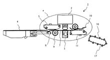
12、13 フィードローラ
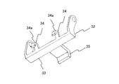
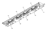
21、31、41、51 搬送装置
22、32、46、56 スプリング
23、37、47、57 ロワフレーム
32、42、52 アーム
48 スプリング
58 突起部
Claims (4)
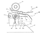
- 第1の搬送ローラと、
前記第1の搬送ローラ側に設けられ、用紙の搬送をガイドし、回転可能な第1の搬送ガイドと、
前記第1の搬送ガイドの下側に配置されて該第1の搬送ガイドと共に搬送路を形成し、前記第1の搬送ガイドとともに回転可能な第2の搬送ガイドと、
前記第2の搬送ガイドに回転可能に設けられるとともに上下方向に移動自在で上昇することで前記第1の搬送ローラに対して接近し、下降することで前記第1の搬送ローラから離間する第2の搬送ローラと、
前記第2の搬送ガイドに基部を固定され、前記第2の搬送ローラを下側から前記第1の搬送ローラ側へ付勢するスプリングとを有し、
単票用紙を搬送する場合は、前記第1の搬送ローラは前記第1の搬送ガイドより前記搬送路側へ突出し、前記第2の搬送ローラは前記スプリングの付勢力により前記第2の搬送ガイドより前記搬送路側に突出して前記第1の搬送ローラに圧接し、この状態で前記第1の搬送ローラと前記第2の搬送ローラとで単票用紙を搬送し、
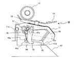
連帳用紙を搬送する場合は、前記スプリングにより前記第2の搬送ローラを付勢した状態で、前記第1の搬送ガイドおよび前記第2の搬送ガイドを前記第2の搬送ガイドの端部に設けた回転軸を中心に傾斜した状態になるように回転させ、これにより前記第1の搬送ローラは前記第1の搬送ガイドの上方に位置し、前記第2の搬送ローラは前記第1の搬送ローラから離れる搬送装置において、
前記第2の搬送ガイドに回転可能に設けられ、回転軸を有する本体部と、前記スプリングの先端部を係止する係止部と、前記本体部に対して前記係止部の反対側に形成され前記第2の搬送ガイドの回転により装置フレーム部材に当接可能な当接部とを有するアーム部材を設け、
前記単票用紙を搬送する場合、前記アーム部材の前記当接部は前記装置フレーム部材から離れており、前記第1の搬送ガイドより前記搬送路側に突出した前記第1の搬送ローラと前記スプリングの付勢力により前記第2の搬送ガイドより前記搬送路側に突出した前記第2の搬送ローラとが圧接し、
前記連帳用紙を搬送する場合、前記第1の搬送ガイドおよび前記第2の搬送ガイドが前記傾斜した状態にまで回転すると、該回転の途中で前記アーム部材の前記当接部が前記装置フレーム部材に当接して該アーム部材が前記第2の搬送ガイドに対して該第2の搬送ガイドの回転方向の逆方向に回転し、この回転により前記係止部が前記スプリングの先端部を前記第1の搬送ローラから離れる方向に押し下げ、これにより前記第2の搬送ローラが前記第1の搬送ガイドから離れる方向に移動することを特徴とする搬送装置。 - 前記単票用紙を搬送する際に、前記第2の搬送ローラを付勢する前記スプリングの付勢力を補助する補助手段を設けた請求項1記載の搬送装置。
- 前記補助手段は、前記第2の搬送ガイドと前記アーム部材の当接部との間に配設され、前記当接部を、前記アーム部材が前記スプリングにより回転される方向に付勢する付勢手段である請求項2記載の搬送装置。
- 前記補助手段は、前記装置フレーム部材に設けられ、前記第2の搬送ガイドが前記連帳用紙搬送状態から前記単票用紙搬送状態に移動する際に前記アーム部材の前記当接部が突き当たる突起部であり、
前記当接部が前記突起部に突き当たることにより前記アーム部材の回転を規制し、該規制により前記アーム部材が前記スプリングの先端部を前記第2の搬送ローラ方向へ押圧する請求項2記載の搬送装置。
Priority Applications (1)
| Application Number | Priority Date | Filing Date | Title |
|---|---|---|---|
| JP2007333720A JP4969435B2 (ja) | 2007-12-26 | 2007-12-26 | 搬送装置 |
Applications Claiming Priority (1)
| Application Number | Priority Date | Filing Date | Title |
|---|---|---|---|
| JP2007333720A JP4969435B2 (ja) | 2007-12-26 | 2007-12-26 | 搬送装置 |
Publications (2)
| Publication Number | Publication Date |
|---|---|
| JP2009154352A JP2009154352A (ja) | 2009-07-16 |
| JP4969435B2 true JP4969435B2 (ja) | 2012-07-04 |
Family
ID=40958895
Family Applications (1)
| Application Number | Title | Priority Date | Filing Date |
|---|---|---|---|
| JP2007333720A Active JP4969435B2 (ja) | 2007-12-26 | 2007-12-26 | 搬送装置 |
Country Status (1)
| Country | Link |
|---|---|
| JP (1) | JP4969435B2 (ja) |
Family Cites Families (3)
| Publication number | Priority date | Publication date | Assignee | Title |
|---|---|---|---|---|
| JPH01169554U (ja) * | 1988-05-18 | 1989-11-30 | ||
| JP2659610B2 (ja) * | 1990-07-19 | 1997-09-30 | 沖電気工業株式会社 | 水平プリンタにおける連続用紙給送機構 |
| JPH07314855A (ja) * | 1994-05-27 | 1995-12-05 | Tec Corp | プリンタ |
-
2007
- 2007-12-26 JP JP2007333720A patent/JP4969435B2/ja active Active
Also Published As
| Publication number | Publication date |
|---|---|
| JP2009154352A (ja) | 2009-07-16 |
Similar Documents
| Publication | Publication Date | Title |
|---|---|---|
| JP5099177B2 (ja) | シートガイド | |
| JP2010083595A (ja) | 画像記録装置 | |
| WO1998058863A1 (en) | Printer | |
| US7878501B2 (en) | Edge regulating device, printing medium cassette, and printing apparatus | |
| JP4194536B2 (ja) | 画像処理装置 | |
| JP4969435B2 (ja) | 搬送装置 | |
| JP5699627B2 (ja) | インクジェット記録装置 | |
| US9586776B2 (en) | Conveyance apparatus and image recording apparatus provided with the same | |
| JP6187340B2 (ja) | 記録装置 | |
| CN104709737B (zh) | 供送装置以及图像记录装置 | |
| JP6642050B2 (ja) | 搬送装置及び画像記録装置 | |
| JP2016124626A (ja) | シート給送装置およびシート処理装置 | |
| CN205395476U (zh) | 输送机构以及打印装置 | |
| CN104943413B (zh) | 馈送装置和图像记录装置 | |
| JP4962455B2 (ja) | 給紙装置及びそれを備えた画像記録装置 | |
| JP4307338B2 (ja) | 画像処理装置 | |
| JP6606969B2 (ja) | 搬送装置及びインクジェット記録装置 | |
| JP6519261B2 (ja) | 搬送装置、及び印刷装置 | |
| JP6179324B2 (ja) | 給送装置 | |
| CN103448384A (zh) | 记录装置以及记录装置中的检测构造 | |
| JP5482649B2 (ja) | シート給送装置 | |
| JP2008273677A (ja) | 予備分離体、自動給送装置 | |
| JP5970823B2 (ja) | プリンタの給紙機構およびプリンタ装置 | |
| JP4499048B2 (ja) | 媒体搬送機構及び画像形成装置 | |
| JP4262114B2 (ja) | 印刷装置 |
Legal Events
| Date | Code | Title | Description |
|---|---|---|---|
| A621 | Written request for application examination |
Free format text: JAPANESE INTERMEDIATE CODE: A621 Effective date: 20091207 |
|
| A711 | Notification of change in applicant |
Free format text: JAPANESE INTERMEDIATE CODE: A712 Effective date: 20110131 |
|
| A977 | Report on retrieval |
Free format text: JAPANESE INTERMEDIATE CODE: A971007 Effective date: 20110708 |
|
| A131 | Notification of reasons for refusal |
Free format text: JAPANESE INTERMEDIATE CODE: A131 Effective date: 20110719 |
|
| A521 | Written amendment |
Free format text: JAPANESE INTERMEDIATE CODE: A523 Effective date: 20110914 |
|
| A02 | Decision of refusal |
Free format text: JAPANESE INTERMEDIATE CODE: A02 Effective date: 20111101 |
|
| A521 | Written amendment |
Free format text: JAPANESE INTERMEDIATE CODE: A523 Effective date: 20120126 |
|
| A911 | Transfer of reconsideration by examiner before appeal (zenchi) |
Free format text: JAPANESE INTERMEDIATE CODE: A911 Effective date: 20120202 |
|
| TRDD | Decision of grant or rejection written | ||
| A01 | Written decision to grant a patent or to grant a registration (utility model) |
Free format text: JAPANESE INTERMEDIATE CODE: A01 Effective date: 20120403 |
|
| A01 | Written decision to grant a patent or to grant a registration (utility model) |
Free format text: JAPANESE INTERMEDIATE CODE: A01 |
|
| A61 | First payment of annual fees (during grant procedure) |
Free format text: JAPANESE INTERMEDIATE CODE: A61 Effective date: 20120403 |
|
| FPAY | Renewal fee payment (event date is renewal date of database) |
Free format text: PAYMENT UNTIL: 20150413 Year of fee payment: 3 |
|
| R150 | Certificate of patent or registration of utility model |
Ref document number: 4969435 Country of ref document: JP Free format text: JAPANESE INTERMEDIATE CODE: R150 Free format text: JAPANESE INTERMEDIATE CODE: R150 |