JP4962017B2 - Roof structure - Google Patents
Roof structure Download PDFInfo
- Publication number
- JP4962017B2 JP4962017B2 JP2007013649A JP2007013649A JP4962017B2 JP 4962017 B2 JP4962017 B2 JP 4962017B2 JP 2007013649 A JP2007013649 A JP 2007013649A JP 2007013649 A JP2007013649 A JP 2007013649A JP 4962017 B2 JP4962017 B2 JP 4962017B2
- Authority
- JP
- Japan
- Prior art keywords
- members
- girder
- beams
- frame unit
- roof
- Prior art date
- Legal status (The legal status is an assumption and is not a legal conclusion. Google has not performed a legal analysis and makes no representation as to the accuracy of the status listed.)
- Expired - Fee Related
Links
Images


Landscapes
- Load-Bearing And Curtain Walls (AREA)
- Residential Or Office Buildings (AREA)
Description
本発明は、建物の屋根上に突出して設ける頂側採光用フレームユニットを用いた屋根構造に関する。 The present invention relates to a roof structure using a top-side lighting frame unit provided so as to protrude on a roof of a building.
建物が隣地に近接して壁面からの採光や通風を得難い場合、あるいは、屋内空間に陽光、空、雲など自然の開放的な雰囲気を取り込んで季節感を高めたい場合、屋根の一部を開口して天窓採光(トップライト)や頂側採光(ハイサイドライト)を得ることがある。 Open a part of the roof when the building is close to the adjacent land and it is difficult to obtain daylight and ventilation from the wall surface, or when you want to enhance the sense of the seasons by incorporating a natural open atmosphere such as sunlight, sky, and clouds into the indoor space. In some cases, skylight lighting (top light) or top side lighting (high side light) may be obtained.
かかる採光のための屋根構造として、例えば特許文献1〜3等には、勾配屋根にドーマー状もしくはこれに類する形状の突出部を設け、その一部を開口して天窓や頂側窓とする構成が記載されている。
As such a roof structure for daylighting, for example, in
また、特許文献4には、屋根面に設けた段差部分に垂直壁部を形成して、この垂直壁部に採光や換気のための頂側窓を設ける構成が開示されている。 Patent Document 4 discloses a configuration in which a vertical wall portion is formed in a stepped portion provided on a roof surface, and a top window for lighting and ventilation is provided on the vertical wall portion.
また、特許文献5には、平屋根の上に略切妻状の枠組みを有する天窓装置を設置する構成が開示されている。
上記のようにして天窓採光や頂側採光を得ようとする場合、開口面積は、構造面や防水面に支障を生じない範囲で可能な限り大きくすることが望まれる。しかしながら、上記のような構造体を従来一般の木造屋根に設置すると、十分な剛性を確保するために開口部の周囲を筋交や耐力面材等で補強しなければならず、間口の大きい開口部を設けるのは難しかった。 When attempting to obtain skylight lighting or top-side lighting as described above, it is desirable that the opening area be as large as possible within a range that does not hinder the structural surface and the waterproof surface. However, when the structure as described above is installed on a conventional general wooden roof, the opening must be reinforced with braces or load-bearing surface materials to ensure sufficient rigidity, and the opening having a large frontage It was difficult to provide a part.
そこで、本発明は、建物の頂部に設置しうる木造の構造体であって、できるだけ間口の大きい開口を、しかも異なる方向に複数箇所設けることができるような頂側採光用フレームユニットを用いた屋根構造を提供するものである。 Therefore, the present invention is a wooden structure that can be installed on the top of a building, and has a roof using a top lighting frame unit that can be provided with a plurality of openings having a large frontage as much as possible in different directions. Provide structure .
上記した目的を達成するため、本発明の屋根構造は、建物の本体部分を構成する木軸架構の上部に形成された、桁材と梁材とからなる水平構面上に、木造の頂側採光用フレームユニットが載置されてなる屋根構造であって、上記頂側採光用フレームユニットは、略矩形平面の四隅に配置された4本の柱材と、上記4本の柱材の脚部を桁行方向及び梁間方向にそれぞれ連結する2本ずつの下桁材及び下梁材と、上記4本の柱材の頭部を桁行方向及び梁間方向にそれぞれ連結する2本ずつの上桁材及び上梁材とを備え、上記各柱材と、各桁材及び各梁材との接合部が、鋼製の連結金物を介して柱勝ちに剛接合され、下桁材と下梁材とによって囲まれた底面が、無床の水平構面として下方の屋内空間に連通し、上桁材と上梁材とによって囲まれた天面が屋根下地構面となされ、各柱材間に形成される一対の桁面及び一対の妻面のうち、少なくとも一つの桁面及び一つの妻面に、それぞれ柱材間の間口全体にわたって開口する頂側窓が設けられてなり、上記木軸架構の梁材及び桁材と、上記頂側採光用フレームユニットの下桁材及び下梁材とが、それぞれ重合状態で鋼製の連結金物により結合されたことを特徴とする。 In order to achieve the above-described object, the roof structure of the present invention is formed on the top side of a wooden structure on a horizontal construction surface formed of girders and beams, which is formed on the top of a wooden frame structure constituting the main body portion of the building. A roof structure on which a lighting frame unit is placed, wherein the top lighting frame unit includes four column members arranged at four corners of a substantially rectangular plane, and leg portions of the four column members. Two lower girders and lower beam members for connecting the heads of the four pillar members in the row direction and the beam direction, respectively. The upper beam member is provided, and the joints between the column members, the beam members, and the beam members are rigidly joined to each other through the steel connecting hardware, and the lower beam member and the lower beam member The enclosed bottom communicates with the indoor space below as a floorless horizontal construction, and is surrounded by upper beams and upper beams. Is formed as a roof base construction surface, and at least one of the pair of girder surfaces and the pair of wive surfaces formed between the column members is opened over the entire frontage between the column members, respectively. A top window is provided, and the beams and girders of the above-mentioned wooden frame structure and the lower girders and lower beams of the above-mentioned frame unit for daylighting are combined with each other in a polymerized state by means of steel coupling hardware. It is characterized by that.
上述のように構成される本発明の屋根構造においては、頂側採光用フレームユニットが、柱材と、桁材・梁材との剛接合により高い剛性が担保されるので、柱材間の間口全体にわたる大開口の頂側窓を、しかも複数の向きに無理なく設けることができる。 In the roof structure of the present invention configured as described above , the top side lighting frame unit has a high rigidity secured by the rigid connection between the column member and the beam member / beam member. A top window with a large opening over the whole can be provided without difficulty in a plurality of directions.
そして、かかる頂側採光用フレームユニットを建物の本体部分の上部に設置した屋根構造によれば、従来の一般木造架構では実現が困難な、きわめて明るく開放感に溢れた屋内空間を実現することができる。 And, according to the roof structure in which such a top-side lighting frame unit is installed on the upper part of the main body of the building, it is possible to realize an extremely bright and open indoor space that is difficult to realize with a conventional general wooden frame. it can.
以下、本発明の実施の形態について図を参照して説明する。 Hereinafter, embodiments of the present invention will be described with reference to the drawings.
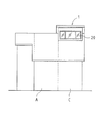
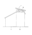
図1は、本発明の実施形態にかかる頂側採光用フレームユニットを設けた木造建物の構造概念図であり、図2及び図3は、図1に示す建物の桁面及び妻面の形状を示した概略立面図である。例示の建物の本体部分は、片側に低く葺き下ろされた切妻屋根を有する第一ブロックAと、第一ブロックAの妻面の棟位置に隣接する第二ブロックBと、第一ブロックA及び第二ブロックBに隣接する第三ブロックCとによって建物本体が構成されている。第三ブロックCの屋根は、第一ブロックAの屋根の葺き下ろし部分に連続する片流れ屋根となっている。 FIG. 1 is a conceptual diagram of the structure of a wooden building provided with a top-side lighting frame unit according to an embodiment of the present invention. FIGS. 2 and 3 show the shapes of the girder and wife surfaces of the building shown in FIG. It is the shown schematic elevation. The main part of the example building includes a first block A having a gable roof that is lowered down on one side, a second block B adjacent to the ridge position of the wife face of the first block A, the first block A and the first block A The building body is constituted by the third block C adjacent to the two blocks B. The roof of the third block C is a single-flow roof that is continuous with a part of the roof of the first block A.
本発明の要部は、第二ブロックBの上部に設置される頂側採光用フレームユニット1にある。頂側採光用フレームユニット1は、第二ブロックBを構成する木軸架構の上部に形成された、適宜の桁材と梁材とからなる水平構面X上に取り付けられて、第一ブロックAの棟よりも上方に突出する。ただし、各ブロックの建物構造や平面形態、屋根形状等は、本発明においては特に限定されない。
The main part of the present invention is in the top-side
頂側採光用フレームユニット1の桁面及び妻面には頂側窓20、30がそれぞれ設けられ、また、勾配の設けられた天面にも天窓40が設けられている。これら窓開口の間口を最大限に確保するための構造について、図4及び図5を参照しつつ説明する。
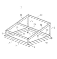
頂側採光用フレームユニット1は、略矩形平面の四隅に配置した4本の柱材5を、桁材(下桁材21及び上桁材22)と梁材(下梁材31及び上梁材32)とによって連結した架構体であり、六つの構面、すなわち、互いに相対する桁面及び妻面と、天面、底面が、すべて高い剛体を備えたフレームとなっている。
The top
図5は、高低差をもって相対する桁面のうち、高いほう(棟側)の桁面を構成する桁フレームの構造を示す。例示の形態において、実用的に想定される柱材5の断面は概ね12cm角程度の正方形であり、これに合わせて下桁材21及び上桁材22の幅も12cm程度とする。下桁材21の高さは約33cm、上桁材22の高さは約27cmとし、これで約4mに及ぶ無柱の間口が形成される。
FIG. 5 shows the structure of a girder frame that constitutes the higher (ridge side) girder surface of the girder surfaces opposed to each other with a height difference. In the illustrated embodiment, the cross-section of the
柱材5と、下桁材21・上桁材22との接合部は、鋼製の連結金物61を介して柱勝ちに剛接合される。例示の連結金物61は、プレートと複数本のほぞパイプとを結合したもので、下桁材21・上桁材22の端部に形成したスリットにプレートが挿し込まれ、柱材5に形成したほぞ孔にほぞパイプが挿入されて、ドリフトピンにより固定される。
The joints between the
下桁材21は、下部構造体、つまりこの例では第二ブロックBの上部に配置された桁材71の上に重合され、複数本の鋼製ほぞパイプ62を介して桁材71と一体に結合される。
The
上記桁フレームと相対する低い方の桁フレームも、同様の構造である。また、上記桁フレームと直交する妻フレームについても、上梁材32が傾斜して配置される点以外は同様の構造である。桁フレームの下桁材21と妻フレームの下梁材31とによって囲まれる底面は、無床の水平構面として下方の屋内空間に連通する。
The lower digit frame opposite to the digit frame has the same structure. The wife frame orthogonal to the girder frame has the same structure except that the
このようにして、各面のフレーム、及びフレーム同士が剛接合された架構により、隅部に筋交や数十cm幅の面材、袖壁等を取り付けたりせずとも、水平力に対して高い剛性が確保される。各接合部位に用いられる連結金物61については、同程度の性能が担保される限り、公知の類似金物であってもよい。
In this way, the frame on each surface and the frame in which the frames are rigidly connected to each other can be used against horizontal force without attaching braces, several tens of centimeters wide surface material, sleeve walls, etc. to the corners. High rigidity is secured. The
そして、一対の桁フレームのうち少なくとも一方、及び、一対の妻フレームのうち少なくとも一方に、間口全体にわたるサッシが取り付けられて、大開口の頂側窓20、30が形成される。上桁材22と上梁材32とによって囲まれる天面は屋根下地構面となるが、ここにも、両上梁材32間の間口全体にわたるサッシが取り付けられて、大開口の天窓40が形成される。例示形態では、天面の傾斜方向中間部に補強のための母屋材23が架設されて天面が二分され、天窓40は下側の略半部に設けられている。なお、本発明において、各サッシの詳細な構造は特に限定しない。
And the sash over the whole frontage is attached to at least one of a pair of girder frames and at least one of a pair of wife frames, and the
図6は、本発明の他の実施の形態を示す。例示形態に係る頂側採光用フレームユニット10は、図4に示した片流れ形状の頂側採光用フレームユニット1を棟合わせにして2体、結合し、両流れの切妻形状としたものである。各部材の接合構造は、図4の頂側採光用フレームユニット1と同様であり、対応する部材に同じ符号を付して説明は省略する。
FIG. 6 shows another embodiment of the present invention. The top-side
このように、本発明によれば、四隅に比較的細い柱材5を用いながら、中間に柱材5がない大開口の頂側窓や天窓を設けることができるので、従来の一般的な木造小屋組では実現が困難な、きわめて明るく開放感に溢れた屋内空間の実現が可能になる。
As described above, according to the present invention, while using the relatively
1 頂側採光用フレームユニット
20 頂側窓
21 下桁材
22 上桁材
30 頂側窓
31 下梁材
32 上梁材
40 天窓
5 柱材
61 連結金物
62 連結金物
71 桁材
81 梁材
DESCRIPTION OF
Claims (1)
上記頂側採光用フレームユニットは、略矩形平面の四隅に配置された4本の柱材と、
上記4本の柱材の脚部を桁行方向及び梁間方向にそれぞれ連結する2本ずつの下桁材及び下梁材と、
上記4本の柱材の頭部を桁行方向及び梁間方向にそれぞれ連結する2本ずつの上桁材及び上梁材とを備え、
上記各柱材と、各桁材及び各梁材との接合部が、鋼製の連結金物を介して柱勝ちに剛接合され、
下桁材と下梁材とによって囲まれた底面が、無床の水平構面として下方の屋内空間に連通し、
上桁材と上梁材とによって囲まれた天面が屋根下地構面となされ、
各柱材間に形成される一対の桁面及び一対の妻面のうち、少なくとも一つの桁面及び一つの妻面に、それぞれ柱材間の間口全体にわたって開口する頂側窓が設けられてなり、
上記木軸架構の梁材及び桁材と、上記頂側採光用フレームユニットの下桁材及び下梁材とが、それぞれ重合状態で鋼製の連結金物により結合されたことを特徴とする屋根構造。 It is a roof structure in which a wooden top-side lighting frame unit is placed on a horizontal structure composed of girders and beams, formed on the top of a wooden frame that forms the main part of the building. ,
The top-side lighting frame unit includes four column members arranged at four corners of a substantially rectangular plane;
Two lower girder members and lower beam members that connect the legs of the four column members in the direction of the beam and between the beams, respectively;
Two upper girder members and upper beam members for connecting the heads of the four column members in the direction of the beam and the direction between the beams, respectively,
The joint between each of the above-mentioned column members, each girder member and each beam member is rigidly joined to the column win through a steel connecting hardware,
The bottom surface surrounded by the lower girder material and the lower beam material communicates with the indoor space below as a floorless horizontal construction surface.
The top surface surrounded by the upper girder material and the upper beam material is the roof foundation construction surface,
Of the pair of digits surfaces and a pair of wife surface formed between the pillar members, at least one digit surfaces and one wife surface, becomes in the top-side window to opening is provided over the entire frontage between the respective pillar ,
A roof structure characterized in that the beams and girders of the wooden frame structure and the lower girders and lower beams of the top-side lighting frame unit are joined together in a polymerized state by steel coupling hardware. .
Priority Applications (1)
| Application Number | Priority Date | Filing Date | Title |
|---|---|---|---|
| JP2007013649A JP4962017B2 (en) | 2007-01-24 | 2007-01-24 | Roof structure |
Applications Claiming Priority (1)
| Application Number | Priority Date | Filing Date | Title |
|---|---|---|---|
| JP2007013649A JP4962017B2 (en) | 2007-01-24 | 2007-01-24 | Roof structure |
Publications (2)
| Publication Number | Publication Date |
|---|---|
| JP2008179969A JP2008179969A (en) | 2008-08-07 |
| JP4962017B2 true JP4962017B2 (en) | 2012-06-27 |
Family
ID=39724068
Family Applications (1)
| Application Number | Title | Priority Date | Filing Date |
|---|---|---|---|
| JP2007013649A Expired - Fee Related JP4962017B2 (en) | 2007-01-24 | 2007-01-24 | Roof structure |
Country Status (1)
| Country | Link |
|---|---|
| JP (1) | JP4962017B2 (en) |
Families Citing this family (1)
| Publication number | Priority date | Publication date | Assignee | Title |
|---|---|---|---|---|
| JP6052252B2 (en) * | 2014-08-11 | 2016-12-27 | 積水ハウス株式会社 | Cantilever beam support structure |
Family Cites Families (3)
| Publication number | Priority date | Publication date | Assignee | Title |
|---|---|---|---|---|
| JPH06158728A (en) * | 1992-11-24 | 1994-06-07 | Mitsuwa:Kk | Construction method of wooden structure |
| JPH09317205A (en) * | 1996-05-30 | 1997-12-09 | Misawa Homes Co Ltd | Method for extending sunroom |
| JP4035643B2 (en) * | 2003-02-03 | 2008-01-23 | 外山 維良 | Wooden frame system unit house |
-
2007
- 2007-01-24 JP JP2007013649A patent/JP4962017B2/en not_active Expired - Fee Related
Also Published As
| Publication number | Publication date |
|---|---|
| JP2008179969A (en) | 2008-08-07 |
Similar Documents
| Publication | Publication Date | Title |
|---|---|---|
| JPH03137342A (en) | Polygonally shaped house | |
| KR100536547B1 (en) | Frame structure of low-rise building | |
| JP4962017B2 (en) | Roof structure | |
| JP4507987B2 (en) | Stiffening structure of sloped roof construction surface | |
| KR100690041B1 (en) | Traditional Thatched House Model | |
| JP3930084B2 (en) | Roof unit | |
| JP6893151B2 (en) | Gate type frame and its construction method | |
| JP4595880B2 (en) | Building unit and unit building using the same | |
| JP4642378B2 (en) | building | |
| JP6479341B2 (en) | building | |
| JP2020111914A (en) | Hut structure | |
| CN211851057U (en) | Landscape corridor frame | |
| JP4178234B2 (en) | Hut structure | |
| JP2001065048A (en) | Wooden frame structure having take-out structure | |
| JP4733408B2 (en) | Unit building | |
| JP2001140395A (en) | Frame structure and building using it | |
| KR20250058332A (en) | Prefabricated frame system | |
| JP2006233420A (en) | Columnless space skeleton system of si construction | |
| JP2020133231A (en) | Wooden building structure | |
| JP4994984B2 (en) | Construction method for wooden buildings | |
| JP2015086656A (en) | Hut structure and housing | |
| JP2016037736A (en) | Wooden frame building | |
| JP2003328444A (en) | Building | |
| JPH0534206U (en) | Two-story house using a unit house | |
| JP2004124397A (en) | Roof structure of house by roof panel |
Legal Events
| Date | Code | Title | Description |
|---|---|---|---|
| A621 | Written request for application examination |
Free format text: JAPANESE INTERMEDIATE CODE: A621 Effective date: 20090908 |
|
| A977 | Report on retrieval |
Free format text: JAPANESE INTERMEDIATE CODE: A971007 Effective date: 20111014 |
|
| A131 | Notification of reasons for refusal |
Free format text: JAPANESE INTERMEDIATE CODE: A131 Effective date: 20111108 |
|
| A521 | Request for written amendment filed |
Free format text: JAPANESE INTERMEDIATE CODE: A523 Effective date: 20111222 |
|
| TRDD | Decision of grant or rejection written | ||
| A01 | Written decision to grant a patent or to grant a registration (utility model) |
Free format text: JAPANESE INTERMEDIATE CODE: A01 Effective date: 20120228 |
|
| A01 | Written decision to grant a patent or to grant a registration (utility model) |
Free format text: JAPANESE INTERMEDIATE CODE: A01 |
|
| A61 | First payment of annual fees (during grant procedure) |
Free format text: JAPANESE INTERMEDIATE CODE: A61 Effective date: 20120312 |
|
| R150 | Certificate of patent or registration of utility model |
Ref document number: 4962017 Country of ref document: JP Free format text: JAPANESE INTERMEDIATE CODE: R150 Free format text: JAPANESE INTERMEDIATE CODE: R150 |
|
| FPAY | Renewal fee payment (event date is renewal date of database) |
Free format text: PAYMENT UNTIL: 20150406 Year of fee payment: 3 |
|
| R250 | Receipt of annual fees |
Free format text: JAPANESE INTERMEDIATE CODE: R250 |
|
| R250 | Receipt of annual fees |
Free format text: JAPANESE INTERMEDIATE CODE: R250 |
|
| R250 | Receipt of annual fees |
Free format text: JAPANESE INTERMEDIATE CODE: R250 |
|
| LAPS | Cancellation because of no payment of annual fees |