JP4961114B2 - tire - Google Patents
tire Download PDFInfo
- Publication number
- JP4961114B2 JP4961114B2 JP2005148214A JP2005148214A JP4961114B2 JP 4961114 B2 JP4961114 B2 JP 4961114B2 JP 2005148214 A JP2005148214 A JP 2005148214A JP 2005148214 A JP2005148214 A JP 2005148214A JP 4961114 B2 JP4961114 B2 JP 4961114B2
- Authority
- JP
- Japan
- Prior art keywords
- rail
- tire
- rubber tire
- width
- traveling
- Prior art date
- Legal status (The legal status is an assumption and is not a legal conclusion. Google has not performed a legal analysis and makes no representation as to the accuracy of the status listed.)
- Expired - Fee Related
Links
Images


Description
本発明は、タイヤに係り、特に道路走行と軌道走行の両方を行うタイヤに関するものである。 The present invention relates to a tire, and more particularly to a tire that performs both road traveling and track traveling.
現在の陸上における主要な交通システムとしては、主に、道路上を走行する路上走行車両によるものと、軌道上を走行する鉄道車両によるものとに二分される。前者は、道路のある場所ならばたいていの目的地まで輸送可能という利点があり、後者は、渋滞等の影響を受けにくく、予定通りの輸送が可能という利点がある。
そこで、近年では、道路と軌道の双方を走行可能とする両用走行車両を用いて、路上走行車両と鉄道車両の双方の利点を備える交通システムの開発が行われている(例えば特許文献1参照)。
Therefore, in recent years, a traffic system having the advantages of both a road traveling vehicle and a railway vehicle has been developed using a dual-purpose traveling vehicle capable of traveling on both a road and a track (see, for example, Patent Document 1). .
上記両用走行車両にあっては、道路上を走行するためのゴムタイヤと軌道のレール上を走行するための車輪とを備え、道路と軌道のいずれを走行するかに応じてゴムタイヤと車輪とを選択的に使用するようになっている。
ところで、両用走行車両では、部品点数の軽減や構造の簡略化を図るために、軌道走行時において、道路走行用のゴムタイヤをレールの上に載せて走行を行うことも検討されている。
The above-mentioned dual-purpose vehicle has a rubber tire for traveling on the road and a wheel for traveling on the rail of the track, and selects the rubber tire and the wheel depending on whether the vehicle travels on the road or the track. Is intended to be used.
By the way, in the dual-purpose traveling vehicle, in order to reduce the number of parts and simplify the structure, it is considered to travel by putting a rubber tire for road traveling on a rail during track traveling.
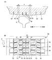
図7は走行時にレールR上にゴムタイヤ200を当接させた状態を示す正面図、図8(A)はゴムタイヤ200のトレッド面に生じる摩耗状態を示す当該ゴムタイヤの中心線方向に沿った断面による断面図、図8(B)は摩耗状態を示す正面図、図9はゴムタイヤの中心線に垂直な断面による断面図である。
FIG. 7 is a front view showing a state in which the
一般に、道路走行用のゴムタイヤ200には、トレッド面201に、周方向に沿った複数の周溝202と各周溝202の間に略幅方向に沿った複数の横溝203とにより区分されてなる複数のブロック204が形成されている。そして、道路走行用のゴムタイヤ200は、一般に、トレッド面201がレールRの頂面の幅よりも広く、ゴムタイヤ200のトレッド面201の幅方向における一部でしかレールRの上面と接しない。
そのような場合、レールの上面に当接するブロック204の中でレールの角(幅方向両端部)以外で接するブロック204は幅方向の全体の範囲でレール上面と接するため幅方向全域で均等に少しずつ摩耗するが、レールの角で接するブロック204aについては当該ブロック204aが傾斜して偏りを生じながらレールRに接触し、その幅方向の一部の範囲M1についてブロック204aが激しく摩耗する。
In general, the
In such a case, among the
また、レールの上面に当接するブロック204の中でレールの左右の角が当接するブロック204,204aにあっては、レール当接時に外側に撓むことを許容する溝が十分な幅で形成されていない場合、レールと強く圧接し、これが大きな摩耗の発生要因となっていた。
特に、両用走行車両は、既存の道路走行車両をベースに部分的に改造して生産を行う場合があり、そのような場合、左右のゴムタイヤ200の輪距の調整には限界があるため、図7に示すように、ゴムタイヤ200のトレッド面201の左右幅における中央位置にレールを当接させることができず、幅方向にオフセットした状態(図7ではタイヤが右側オフセットした状態)で当接しながら走行が行われていた。そして、このようにオフセットされた状態で軌道走行が行われると、上記レールの左右の角が当接するブロック204,204aにあっては、タイヤのオフセット方向となるブロック204aについて荷重が大きくなって摩耗量が増大していた。
Further, in the
In particular, the dual-purpose traveling vehicle may be partially modified based on the existing road traveling vehicle for production. In such a case, the adjustment of the wheel distance of the left and
また、横溝203は周方向について所定本数ごと(図8(B)及び図9の例では三本ごと)に他よりも幅が広い横溝203aが形成されている。そして、この幅の広い横溝203aによって区分される三つのブロック204の中で最初にレールRに当接するブロック204b(横溝203aのすぐ上流側に位置するブロック)の上流側端部M2は、その当接時において局地的な接触状態となるので、やはり摩耗が激しくなる。
Further, the
このように、通常の道路走行用のタイヤを両用走行車両に搭載して、レールの走行に使用した場合、十分な長期走行を行うための耐久性が得られないという問題があった。
本発明は、道路とレールの双方の十分な長期走行に耐久し得るタイヤを提供することをその目的とする。
また、本発明は、レールの走行時にも適度の粘着力(摩擦力)を維持し得るタイヤを提供することをその目的とする。
As described above, when a normal road traveling tire is mounted on a two-way traveling vehicle and used for traveling on a rail, there is a problem that durability for sufficient long-term traveling cannot be obtained.
An object of the present invention is to provide a tire that can endure long enough traveling on both roads and rails.
Another object of the present invention is to provide a tire that can maintain an appropriate adhesive force (frictional force) even when the rail is running.
請求項1記載の発明は、道路上の走行と軌道のレール上の走行の両方に使用されるタイヤであって、トレッド面上にタイヤ周方向に沿って複数形成される周溝の中で、レールの当接領域の両端部に形成される二本の周溝について、前記レールの当接領域の範囲に含まれる他の周溝よりも幅を広く形成した、という構成を採っている。 The invention according to claim 1 is a tire used for both running on a road and running on a rail of a track, and a plurality of circumferential grooves formed along a tire circumferential direction on a tread surface. The two circumferential grooves formed at both ends of the rail contact area are configured to be wider than other peripheral grooves included in the range of the rail contact area.
請求項1記載の発明は、トレッド面におけるレールの当接領域にレールの上面を当接させて軌道走行が行われる。その際、レールの当接領域の両側には、他の周溝よりも幅が広い周溝が形成されているので、当該幅広の周溝と隣接する他の周溝との間となる部分を、レール当接時に幅広の周溝側に逃げるように撓ませることができ、レールとの圧接状態を緩和することができる。 According to the first aspect of the present invention, the track travel is performed by bringing the upper surface of the rail into contact with the contact region of the rail on the tread surface. At that time, circumferential grooves wider than the other circumferential grooves are formed on both sides of the contact area of the rail, so that the portion between the wide circumferential groove and another adjacent circumferential groove is It can be bent so as to escape toward the wide circumferential groove when the rail is in contact, and the pressure contact state with the rail can be relaxed.
なお、レールがタイヤのトレッド面の幅方向についていずれの位置で当接するかが、車体における左右のタイヤの輪距、レールの軌間寸法等により事前に分かる場合には、それらに基づいてタイヤのトレッド面上に二本の幅広の溝の形成位置を決めることが好ましい。
またあるいは、トレッド面上の任意の位置(好ましくは中央位置)をレールの当接領域と決め、その両側に幅広の周溝を形成すると共に、軌道走行時に当接領域にレールが当接するように輪距を調節してタイヤを車両に取り付けることが好ましい。
In addition, if it is known in advance by the wheel width of the left and right tires in the vehicle body, the rail gauge size, etc., where the rail contacts in the width direction of the tread surface of the tire, the tire tread It is preferable to determine the formation position of two wide grooves on the surface.
Alternatively, an arbitrary position (preferably the center position) on the tread surface is determined as the rail contact area, wide circumferential grooves are formed on both sides thereof, and the rail is in contact with the contact area during track running. It is preferable to adjust the wheel distance and attach the tire to the vehicle.
また、当接領域の幅(両側の幅広の周溝を含まない踏面のみの幅)については、当接領域の幅に両側の周溝の幅を加えた値がレールの上面幅以上であって当接領域のみの幅がレールの上面幅以下となる範囲が望ましい。また、この範囲について数ミリ前後の誤差があっても良い。
さらに、走行を行う軌道のレール上面幅が既知であれば、これを基準に当接領域の幅を設定し、既知でない場合には、60.33[mm](30kgレール),62.71[mm](37kgレール),64[mm](40kgレール),65[mm](50kgNレール,50kgTレール,60kgレール),67.87[mm](50kgPSレール)等の規格幅を基準に当接領域の幅を設定することが好ましい。
As for the width of the contact area (the width of only the tread surface not including the wide circumferential grooves on both sides), the value obtained by adding the width of the circumferential grooves on both sides to the width of the contact area is equal to or greater than the upper surface width of the rail. A range in which the width of only the contact area is less than or equal to the upper surface width of the rail is desirable. There may be an error of about several millimeters in this range.
Furthermore, if the rail upper surface width of the track to be run is known, the width of the contact area is set based on this, and if it is not known, 60.33 [mm] (30 kg rail), 62.71 [mm] (37 kg) Rail), 64 [mm] (40 kg rail), 65 [mm] (50 kg N rail, 50 kg T rail, 60 kg rail), 67.87 [mm] (50 kg PS rail), etc. It is preferable.
また、「二本の周溝について、他の周溝よりも幅を広く形成」するとは、二本の周溝の幅をそれら以外のいずれの周溝よりも広く設定することを意味する。さらに、これら幅広の周溝については、同じ幅としても良いし、いずれか一方を他方よりも幅広としても良い。
なお、溝の幅とは、周溝の幅が全周に渡ってほぼ均一であればその幅をいい、全周が不均一であればその平均的な値をいうものとする。
Further, “the two circumferential grooves are formed wider than the other circumferential grooves” means that the widths of the two circumferential grooves are set wider than any other circumferential groove. Further, these wide circumferential grooves may have the same width, or one of them may be wider than the other.
The width of the groove means the width if the width of the circumferential groove is substantially uniform over the entire circumference, and the average value if the width of the circumferential groove is not uniform.
請求項2記載の発明は、請求項1記載の発明と同様の構成を備えると共に、複数の周溝により区分される複数の分割面部の中で、レールの当接領域のタイヤの幅方向における端部に位置する分割面部を他の分割面部よりも硬くした、という構成を採っている。
The invention according to
タイヤのトレッド面において、レールの幅方向における端部(レールの角に相当する部分)が当接する部分が他の部分よりも摩耗する。
従って、周溝により区分された複数の分割面部の中で、レールの当接領域の端部(タイヤの幅方向における端部)に位置する分割面部を他の分割面部よりも硬くする。
これにより、摩耗が生じやすい分割面部からの摩耗の発生及び進行が抑制される。
In the tread surface of the tire, a portion where an end portion (a portion corresponding to a corner of the rail) in the width direction of the rail abuts wears more than the other portions.
Accordingly, among the plurality of divided surface portions divided by the circumferential groove, the divided surface portion positioned at the end portion (the end portion in the tire width direction) of the rail contact region is made harder than the other divided surface portions.
Thereby, generation | occurrence | production and progress of the wear from the division surface part which is easy to produce wear are suppressed.
なお、「分割面部」とは、周溝と周溝の間となる部分のことを示す。例えば、後述する発明の最良の形態の記載において示すゴムタイヤ50の周方向に沿って一列に並んだ複数のブロックが「分割面部」に相当する。
なお、レールの当接領域の両端部に位置する分割面部のいずれか一方を硬くする構成としても良いが、両端部の両方の分割面部を硬くすることがより望ましい。
また、「レールの当接領域」の配置及び幅については、請求項1記載の発明と同様である。
なお、タイヤのトレッド面において、上記レールの当接領域のタイヤの幅方向における端部に位置する分割面部以外の部分については、軌道走行又は道路走行において一般的に必要となる摩擦力を確保するための一般的な固さとすることが望ましい。
The “divided surface portion” refers to a portion that is between the circumferential grooves. For example, a plurality of blocks arranged in a line along the circumferential direction of the
In addition, although it is good also as a structure which hardens any one of the division surface parts located in the both ends of the contact area | region of a rail, it is more desirable to make both the division surface parts of both ends hard.
The arrangement and width of the “rail contact area” are the same as in the first aspect of the invention.
It should be noted that, on the tire tread surface, a frictional force generally required for track traveling or road traveling is ensured for portions other than the divided surface portion located at the end of the contact region of the rail in the width direction of the tire. It is desirable to have a general hardness for.
請求項3記載の発明は、請求項2記載の発明と同様の構成を備えると共に、レールの当接領域内に形成された、タイヤ周方向に沿って密集して並んだ複数のブロックの集合のそれぞれについて、周方向における前進回転方向側の端部に位置するブロックの踏面を他のブロックの踏面よりも硬くした、という構成を採っている。
The invention described in
タイヤのトレッド面に周溝、横溝などが形成されると、それらによって仕切られて複数のブロックが形成される。そして、トレッド面上に幅の広い横溝が一定の間隔で形成されると、各ブロックは周方向について複数個ずつで固まって並んだ集合状態となる(例えば、図9参照)。そして、レールの当接領域内では、当該固まりとなる複数のブロックの中で、タイヤの回転方向の先頭となるブロックの踏面が走行時において最初にレールに当接するので、最も摩耗を生じやすい。
従って、複数のブロックの集合ごとに、周方向における一方の端部に位置するブロックの踏面の少なくとも当該一方の端部側部分をトレッド面の他の部分よりも硬くする。そして、車両への取り付けの際には、硬くしたブロックの端部が車両前進時の回転において、回転方向の先頭側となるようにタイヤの取り付けを行う。
これにより、軌道上の前進走行時おいて、摩耗が生じやすい複数のブロックの先頭端部からの摩耗の発生及び進行が抑制される。
When circumferential grooves, lateral grooves, and the like are formed on the tread surface of the tire, a plurality of blocks are formed by being partitioned by them. When wide lateral grooves are formed on the tread surface at regular intervals, each block is in a collective state in which a plurality of blocks are fixed and arranged in the circumferential direction (see, for example, FIG. 9). In the contact area of the rail, the tread surface of the block that is the head in the tire rotation direction comes into contact with the rail first during traveling, among the plurality of blocks that form the mass, and thus wear is most likely to occur.
Therefore, for each set of a plurality of blocks, at least the one end portion side portion of the tread surface of the block located at one end portion in the circumferential direction is made harder than the other portion of the tread surface. Then, when attaching to the vehicle, the tire is attached so that the end of the hardened block is on the leading side in the rotational direction during rotation when the vehicle is moving forward.
As a result, during forward traveling on the track, the occurrence and progression of wear from the leading end portions of the plurality of blocks that are likely to be worn are suppressed.
なお、上記構成において、複数のブロックの集合の中で、周方向における一方の端部に位置するブロックの踏面の中のさらに前方の端部が最も摩耗しやすいので当該端部のみを硬くのみを硬くしても良い。
また、タイヤのトレッド面において上記周方向における一方の端部側のブロック以外の部分については、軌道走行又は道路走行において、必要となる摩擦力を維持するための一般的な固さとすることが望ましい。
また、「レールの当接領域」の配置及び幅については、請求項1記載の発明と同様である。
In the above configuration, the front end of the tread surface of the block located at one end in the circumferential direction among the set of blocks is most likely to wear, so only the end is hard. It may be hard.
In addition, it is desirable that portions other than the block on one end side in the circumferential direction on the tread surface of the tire have a general hardness for maintaining a necessary frictional force during track running or road running. .
The arrangement and width of the “rail contact area” are the same as in the first aspect of the invention.
請求項1記載の発明は、トレッド面におけるレールの当接領域の両側に、幅広の周溝を形成したので、当該周溝に区分される部分を幅広の周溝側に逃げるように変形させることができ、レールとの圧接状態を緩和することで、レールの当接領域両端部で生じる過剰な摩耗を抑制することができ、トレッド面の耐摩耗性を向上することが可能となる。
また、既存の道路走行車両を改造して両用走行車両を製造した場合などの事情により、フレームに対してタイヤの左右位置の位置調節が制限されることで、タイヤの中心位置からオフセットしてレールを当接せざるを得ないような場合であってもそのオフセット量に応じて幅広の周溝を形成することにより、タイヤの摩耗を抑制し、耐久性の向上を図ることが可能となる。
また、本発明は、上述のように、道路とレールの双方を走行する車両にも、その使用に耐久し得るタイヤを提供することが可能となる。
According to the first aspect of the present invention, since the wide circumferential groove is formed on both sides of the contact area of the rail on the tread surface, the portion divided by the circumferential groove is deformed so as to escape to the wide circumferential groove side. By relaxing the pressure contact state with the rail, it is possible to suppress excessive wear that occurs at both ends of the contact area of the rail, and to improve the wear resistance of the tread surface.
Also, the rails are offset from the center position of the tire by restricting the position adjustment of the left and right positions of the tire with respect to the frame due to circumstances such as modifying an existing road vehicle and manufacturing a dual-purpose vehicle. Even in the case where it is necessary to contact the tire, by forming a wide circumferential groove according to the offset amount, it is possible to suppress wear of the tire and improve durability.
In addition, as described above, the present invention can provide a tire that can be used for a vehicle traveling on both roads and rails.
請求項2記載の発明では、周溝により区分された複数の分割面部の中で、レールの当接領域の端部に位置する分割面部を他の分割面部よりも硬くしたので、軌道走行時おいて、摩耗が生じやすいレールの角部の当接部位からの摩耗の発生及び進行を抑制することができ、トレッド面の耐摩耗性を向上することが可能となる。
また、本発明は、レールの当接領域の端部に位置する分割面部以外の分割面部については硬くしないので、レールに対して、また、道路走行時にも、適度の粘着性を確保することができ、安定した走行を行うことが可能となる。
また、既存の道路走行車両を改造して両用走行車両を製造した場合などの事情により、タイヤの中心位置からオフセットしてレールを当接せざるを得ないような場合であってもそのオフセット量に応じて硬くする分割面部の配置を選択することにより、タイヤの摩耗を抑制し、耐久性の向上を図ることが可能となる。
また、本発明は、上述のように、道路とレールの双方を走行する車両にも、その使用に耐久し得るタイヤを提供することが可能となる。
In the invention according to
In addition, since the present invention does not harden the divided surface portions other than the divided surface portion located at the end of the contact area of the rail, it is possible to ensure appropriate adhesion to the rail and also when traveling on the road. And stable running is possible.
In addition, even if the existing road traveling vehicle is modified and a dual-purpose traveling vehicle is manufactured, the offset amount is offset even if the rail must be brought into contact with the center position of the tire. By selecting the arrangement of the divided surface portions to be hardened according to the above, it is possible to suppress the wear of the tire and improve the durability.
In addition, as described above, the present invention can provide a tire that can be used for a vehicle traveling on both roads and rails.
請求項3記載の発明では、タイヤ周方向に沿って密集して並んだ複数のブロックの集合の、周方向一端部側のブロックの踏面を他のブロックよりも硬くしたので、硬くしたブロックが先頭側となるようにタイヤを車両に装備することで、軌道走行時おいて、摩耗が生じやすい先頭端部からの摩耗の発生及び進行を抑制することができ、トレッド面の耐摩耗性を向上することが可能となる。
また、本発明は、集合の中で一端部側となるブロック以外のブロックについては硬くしないので、レールに対して、また、道路走行時にも、適度の粘着性を確保することができ、安定した走行を行うことが可能となる。
また、既存の道路走行車両を改造して両用走行車両を製造した場合などの事情により、タイヤの中心位置からオフセットしてレールを当接せざるを得ないような場合であってもそのオフセット量に応じて硬くするブロックの配置を選択することにより、タイヤの摩耗を抑制し、耐久性の向上を図ることが可能となる。
また、本発明は、上述のように、道路とレールの双方を走行する車両にも、その使用に耐久し得るタイヤを提供することが可能となる。
In the invention according to
In addition, the present invention does not harden the blocks other than the block on one end side in the assembly, so that it can secure an appropriate degree of adhesiveness to the rail and also when traveling on the road, and is stable. It is possible to run.
In addition, even if the existing road traveling vehicle is modified and a dual-purpose traveling vehicle is manufactured, the offset amount is offset even if the rail must be brought into contact with the center position of the tire. By selecting the arrangement of the blocks to be hardened according to the above, it is possible to suppress the wear of the tire and improve the durability.
In addition, as described above, the present invention can provide a tire that can be used for a vehicle traveling on both roads and rails.
(発明の実施形態の概略)
本発明の実施形態たるゴムタイヤ50について図1乃至図3に基づいて説明する。ゴムタイヤ50は、道路上の走行と軌道のレール上の走行の両方に使用される。
また、ゴムタイヤ50は、従来の鉄道輸送システムとバス輸送システムとの双方の利点を兼ね備えた新たな交通システムである「デュアルモード交通システム」のデュアルモード車両1において、駆動輪として使用されるものである。
(Outline of Embodiment of the Invention)
A
The
(デュアルモード交通システム)
デュアルモード交通システムは、図1に示すように、デュアルモード車両1と、走行モード変換用構造体10と、デュアルモード車両1が走行可能な図示されていない道路と、軌道40と、を備えており、走行モード変換用構造体10を介して、道路走行モードにあるデュアルモード車両1を軌道走行モードに変換する一方、軌道走行モードにあるデュアルモード車両1を道路走行モードに変換するものである。
道路は、デュアルモード車両1が走行可能な路面を有している。
軌道40は、図1に示すように、デュアルモード車両1が走行可能な2本のレールRを有しており、これらレールRの軌間寸法は規格化された値(1067[mm])とされている。また、各レールRはその頂部の幅が65[mm]に設定されたいわゆる50kgNレールである。つまり、軌道40は、通常の鉄道車両も走行できる規格となっており、通常の鉄道車両とデュアルモード車両1の走行時間を異ならせることで軌道40の共用を図ることも可能となっている。
(Dual mode transportation system)
As shown in FIG. 1, the dual mode traffic system includes a dual mode vehicle 1, a travel
The road has a road surface on which the dual mode vehicle 1 can travel.
As shown in FIG. 1, the
(デュアルモード車両)
デュアルモード車両1は、図1に示すように、車体2と、車体2の前方において一対で回転可能に支持された前方ゴムタイヤ3と、車体2の後方において一対で回転可能に支持された第一、第二の後方ゴムタイヤ4,50と、車体2の前方及び後方に昇降自在に配設された車軸5a,6aを中心に回転する軌道走行用の前方案内輪5及び後方案内輪6とを備えている。
デュアルモード車両1は、前方ゴムタイヤ3及び第一、第二の後方ゴムタイヤ4,50による道路走行と、前方案内輪5、後方案内輪6及び第二の後方ゴムタイヤ50による軌道走行と、の双方を自在に切り換えて実現させることができるものである。
(Dual mode vehicle)
As shown in FIG. 1, the dual mode vehicle 1 includes a
The dual-mode vehicle 1 performs both the road traveling by the
車体2は、複数の乗客を搭乗させる構造を有している。本実施の形態においては、図1に示すようなマイクロバスの車体2を採用しており、運転手を含めて約30人を搭乗させることができる。
The
前方案内輪5及び後方案内輪6は、鉄等の金属で構成されており、各々左右1個ずつ設けられている。左右の前方案内輪5及び後方案内輪6は、各々前車軸5a及び後車軸6aで連結されている。また、前方案内輪5及び後方案内輪6は、前後車軸5a,6a及びアーム5b,6bを介して車体2のシャーシ2aの前後に回動自在に取り付けられており、図示されていない油圧アクチュエータの伸縮により上方及び下方に回動するように構成されている。
The
道路走行時においては、油圧アクチュエータの収縮により前方案内輪5及び後方案内輪6を上方に回動させて、前方ゴムタイヤ3及び第一、第二の後方ゴムタイヤ4,50より上方で固定する。
一方、軌道走行時には、油圧アクチュエータの伸長により前方案内輪5及び後方案内輪6を下方に回動させて、軌道40のレールR上面に当接させる。軌道走行時においては、前方案内輪5は車体2の前方荷重を支持し、後方案内輪6は車体2の後方荷重の一部を支持することとなる。また、このとき、第二の後方ゴムタイヤ50は、レールRとの接触を維持できる高さに油圧アクチュエータの伸長量は調節され、第二の後方ゴムタイヤ50が後方荷重の残る一部を支持することとなる。
When traveling on the road, the
On the other hand, at the time of running on the track, the
また、前方案内輪5及び後方案内輪6は、フランジ5c,6c及び勾配を有する踏面5d,6dを備えており、軌道案内機能を果たす。このため、駆動輪である第二の後方ゴムタイヤ50に踏面勾配やフランジが設けられていなくても、デュアルモード車両1は、レールRに沿って正確に軌道走行を行うことができる。本実施の形態においては、前方案内輪5及び後方案内輪6のフランジ5c,6cの高さを「約33mm」に設定している。
Further, the
左右の前方ゴムタイヤ3は、車体2に対して水平な支軸により回転可能に支持されており、車体2の運転席のハンドルに連結された図示しないステアリング機構により左右の前方ゴムタイヤ3が同方向を維持しながら操舵可能となっている。
The left and right
第一、第二の後方ゴムタイヤ4,50は、いずれも、図1に示すように、車体2のシャーシ2aに取り付けられた後タイヤ用車軸4aに左右一対で軸支されており、第一の後方ゴムタイヤ4は左右方向における両外側にそれぞれ配設され、第二の後方ゴムタイヤ50は、それぞれ第一の後方ゴムタイヤ4の内側に隣接して配設されている。つまり、左右の第一の後方ゴムタイヤ4と左右の第二の後方ゴムタイヤ50とは、同一軸上に配設されている。
そして、第一、第二の後方ゴムタイヤ4,50は、前方ゴムタイヤ3とともに道路走行時に車体2の荷重を支持するとともに、(図示されていない)エンジン及び動力伝達装置によって駆動されて道路走行時及び軌道走行時に駆動輪として機能するものである。また、軌道走行時には、内側となる第二の後方ゴムタイヤ50のみが軌道40を構成するレールR上面に当接して駆動力を発生させる。
As shown in FIG. 1, the first and second
The first and second
(第二の後方ゴムタイヤの詳細説明)
上記前方ゴムタイヤ3と第一の後方ゴムタイヤ4は、従前から一般的に使用されるものと同じゴムタイヤが使用される(例えば、図7〜図9に示すゴムタイヤ)。一方、第二の後方ゴムタイヤ50は、そのトレッド面51よりも幅が狭いレールRの上面に当接して回転駆動を行い、デュアルモード車両1の走行移動力を生じさせる必要があるため、軌道走行時のレールRに対する耐摩耗性が高く、レールRに対して良好な走行を維持するのに十分な粘着力を備えたゴムタイヤが使用される。
(Detailed explanation of the second rear rubber tire)
The
かかる第二の後方ゴムタイヤ50について、図2及び図3に基づいて詳細に説明する。図2(A)はゴムタイヤ50の中心線方向に沿った断面図、図2(B)はその正面図、図3は後述するレールの当接領域の幅の設定例を示す説明図である。
なお、図2及び図3に示す第二の後方ゴムタイヤ50は、デュアルモード車両1に搭乗して進行方向前方を向いた状態で左側のゴムタイヤを示しているが、右側の第二の後方ゴムタイヤ50については、後タイヤ用車軸4aに対する垂直平面を基準として図示のものと鏡面対称となる構造のものが使用されるものとし、その説明は省略する。
The second
The second
図示の如く、第二の後方ゴムタイヤ50のトレッド面51には、その周方向に沿って幅の異なる二種類の周溝52,53が複数形成されている。そして、各周溝52,53の間には略幅方向に沿って横溝54と当該横溝54よりも幅が広い横溝57とが形成されている。そして、これら周溝52,53、及び横溝54,57によりトレッド面51が区分されることでブロック55がいくつも形成されている。
As shown in the figure, the
当接領域Tの左右両側に形成される二本の周溝53については、他のいずれの周溝52よりもその溝幅が広く設定されている。
レールの当接領域Tは、レールRの上面がトレッド面51に当接する範囲を示す。第二の後方ゴムタイヤ50は、そのトレッド面51の左右幅がレールRの上面の幅よりも大きいものが使用され、直線区間の軌道走行時には、トレッド面51の一定の範囲のみでレールRの上面に接することとなる。
車体左側の第二の後方ゴムタイヤ50と車体右側の第二の後方ゴムタイヤ50の間の距離(輪距)は、車体2のシャーシ2aの横幅に応じて決定され、そのほか、軌道40の軌間寸法、偏倚量も考慮され得る。一方、軌道40の左側のレールRと右側のレールRとの間の距離(軌間寸法)は、複数あるいずれかの規格の中から選択されて決定される(本実施形態では軌間寸法は1067[mm])。左右の第二の後方ゴムタイヤ50の輪距と左右のレールRの軌間寸法とが事前に分かっている場合には、左側の第二の後方ゴムタイヤ50と右側の第二の後方ゴムタイヤ50との中間となる位置と、左側のレールRと右側のレールRとの中間の位置とが一致するように配置したときに、左右それぞれの第二の後方ゴムタイヤ50のトレッド面51に各レールRが当接する範囲をレールの当接領域Tと予め定めることができる。
The two
The rail contact region T indicates a range in which the upper surface of the rail R contacts the
The distance (wheel distance) between the second
また、レールの当接領域Tの左右の幅は、レールRの幅に応じて決定される。レールRの幅は、複数種のレール幅の規格の中からいずれかの幅を選択して決定される。本実施形態では、レールRは前述したように、いわゆる50kgNレールであり、その上部の幅が65[mm]となっている。そして、レールの当接領域Tの幅は、図2(A)に示すように、レールRの上部の幅と等しく設定している。なお、当接領域Tの幅は後述するように、レールRと一致することが望ましいが、これに限定されるものではない。 Further, the left and right widths of the rail contact region T are determined according to the width of the rail R. The width of the rail R is determined by selecting one of a plurality of types of rail width standards. In the present embodiment, the rail R is a so-called 50 kgN rail as described above, and the width of the upper portion thereof is 65 [mm]. And the width | variety of the contact area | region T of a rail is set equal to the width | variety of the upper part of the rail R, as shown to FIG. 2 (A). As will be described later, it is desirable that the width of the contact region T coincides with the rail R, but is not limited thereto.
そして、事前に定まるレールの当接領域Tの両側に幅広の周溝53が形成されるようになっている。幅広の周溝53の幅は、他の周溝52より大きければ良い。
レールの当接領域Tと左右両側の周溝53の幅を含む範囲を変位領域とした場合、当該変位領域の幅は、本実施形態では一例として80[mm]に設定している。前述したように、当接領域Tの幅を65[mm]とすると、本実施形態では、周溝53の幅を左右それぞれ7.5[mm]に設定されていることになる。なお、変位領域の幅及び周溝53の数値は一例であり、これらに限定されるものではなく、(1)車両の固定軸距(前方案内輪5と後方案内輪6の各車軸5a,6aの間の距離)、(2)前方案内輪5と後方案内輪6の各フランジ5c,6cとレールRとの遊間、(3)第二の後方ゴムタイヤ50の輪距、(4)曲線のレールRにおける偏倚量及び走行を行う軌道に生じ得るレールRの曲率等の条件から適宜選択することが望ましい。
A wide
When a range including the width of the rail contact area T and the
第二の後方ゴムタイヤ50のトレッド面51において当接領域Tの配置が定まり、その両側となる位置に、他の周溝52よりも幅広となる二本の周溝53を当接領域Tの左右幅と等しい間隔を空けて設けることにより、軌道走行時において、第二の後方ゴムタイヤ50がレールRの上面に当接したときに、当接領域Tの左右両端に位置するブロック56の列が、それぞれ幅広の周溝53側に逃げるように撓むことができ、当接領域Tの左右両側に位置するブロック56の過剰な摩耗を抑制することができる。
また、当接領域Tの左右両側に位置する各ブロック56は、いずれも、その左右幅方向について全幅の範囲でレールRの上面に当接するので、幅方向の一部でのみ当接する場合と比較して過剰な摩耗を抑制することが可能となる。
The arrangement of the contact region T is determined on the
In addition, each of the
なお、図2では、当接領域Tの幅とレールRの上面幅とを一致させることが好ましいが、厳格に一致させなくとも良い。例えば、周溝53の幅をHとした場合、TがR以下となり(図2(A)の場合)、T+2HがR以上となる範囲(図3の場合)で当接領域Tの幅を設定しても良い(つまり、(R−2H)≦T≦R)。
In FIG. 2, it is preferable to match the width of the contact region T with the width of the upper surface of the rail R, but it is not necessary to match exactly. For example, when the width of the
(走行モード変換用構造体)
走行モード変換用構造体10は、前記したデュアルモード車両1の走行モードを道路走行モードから軌道走行モードに円滑に変換するためのものである。
かかる走行モード変換用構造体10は、道路走行モードの状態で軌道40の各レールRの敷設領域内への円滑な侵入を可能とする土台と、各レールRの敷設領域内においてデュアルモード車両1がレールに沿って進行することで前方案内輪5及び後方案内輪6を左右方向についてズレを生じないように各レールRに導くためのガイドとから主に構成されている。
(Travel mode conversion structure)
The travel
The traveling
つまり、デュアルモード車両1は、各ゴムタイヤ3,4及び50が同時に接地する平面よりも前方案内輪5及び後方案内輪6が上方で待機した状態である道路走行モードで土台上に侵入し、前方案内輪5及び後方案内輪6を前記接地面に接地する高さまでおろした状態で各レールRに沿って前進する。すると、ガイドにより前方案内輪5と後方案内輪6が順番に各レールRに載るように誘導される。そして、前方ゴムタイヤ3がレールRの上面高さよりも持ち上げられる高さまで前方案内輪5をより下降させることで、軌道走行モードに移行されるようになっている。
That is, the dual mode vehicle 1 enters the base in the road traveling mode in which the
(実施形態の効果)
このように、デュアルモード交通システム1では、軌道40の一部区間に設けられる走行モード変換用構造体10を用いて、デュアルモード車両1の道路走行モードから軌道走行モードに容易且つ迅速に変換することが可能である。
(Effect of embodiment)
As described above, in the dual mode traffic system 1, the driving
また、デュアルモード車両1は、第二の後方ゴムタイヤ50として、そのトレッド面51におけるレールの当接領域Tの両側に、幅広の周溝53を形成したので、当該各周溝53のすぐ内側に並ぶブロック56について、レールRとの圧接時に、周溝53側に逃げるように変形させることができ、その圧接状態を緩和することで過剰な摩耗を抑制することができ、トレッド面の耐摩耗性を向上することが可能となる。
また、上記第二の後方ゴムタイヤ50は、図2または図3のように、当接領域Tの幅をレールRの上面幅により近い値とすることにより、当接領域T内で幅方向両端に位置するブロック56を、その全幅の範囲でレールRの上面に当接させることができる。従って、幅方向の一部で当接する状態を回避して、加圧力を分散し、かかる観点からも過剰な摩耗を抑制することができ、このような作用からも、トレッド面の耐摩耗性を向上することが可能となる。
つまり、デュアルモード車両1では上記第二の後方ゴムタイヤ50を使用することにより、道路上での走行性能を維持しつつも、軌道走行時に過剰な摩耗を抑制し、両モードでの安定した走行を長期に渡って維持することが可能となる。
また、仮に、既存の道路走行車両を改造してデュアルモード車両1を製造した場合などの事情により、フレームに対して第二の後方ゴムタイヤ50の左右位置の位置調節が制限されることで、第二の後方ゴムタイヤ50の幅方向中心位置からオフセットしてレールRを当接せざるを得ないような場合であってもそのオフセット量に応じて幅広の周溝56を形成することにより、タイヤの摩耗を抑制し、耐久性の向上を図ることが可能となる。
なお、本実施形態では、第二の後方ゴムタイヤ50は、トレッド面51の幅方向における中心位置に対してレールRの幅方向における中心位置が20[mm]内側方向にオフセットして当接しているが、かかるオフセットに対応してレールの当接領域Tもトレッド面の中心位置から20[mm]内側にオフセットして配置設定されているため、効果的に摩耗低減が図られている。
Further, since the dual mode vehicle 1 has the wide
Further, as shown in FIG. 2 or FIG. 3, the second
That is, in the dual mode vehicle 1, by using the second
In addition, for example, when the dual-mode vehicle 1 is manufactured by remodeling an existing road traveling vehicle, the position adjustment of the left and right positions of the second
In the present embodiment, the second
(第二の後方ゴムタイヤの第二の例)
第二の後方ゴムタイヤの第二の例を図4に示す。図4は第二の後方ゴムタイヤ50Aの正面図を示す。
この第二の後方ゴムタイヤ50Aは、デュアルモード車両1に搭乗して進行方向前方を向いた状態で左側のゴムタイヤを示しているが、右側の第二の後方ゴムタイヤ50Aについては、後タイヤ用車軸4aに対する垂直平面を基準として図示のものと鏡面対称となる構造のものが使用されるものとし、その説明は省略する。
(Second example of second rear rubber tire)
A second example of the second rear rubber tire is shown in FIG. FIG. 4 shows a front view of the second
The second
図4に示すように、第二の後方ゴムタイヤ50Aのトレッド面51Aには、その周方向に沿って幅の異なる二種類の周溝52A,53Aが複数形成されている。そして、トレッド面51Aは、各周溝52A,53Aにより、周方向に沿って複数の分割面部に分割され、さらに、略幅方向に沿って形成された横溝54Aと当該横溝54Aよりも幅が広い横溝57Aとにより、ブロック55A,56Aがいくつも形成されている。
As shown in FIG. 4, the
ここで、周溝53Aは、前述した周溝53と同じようにレールの当接領域Tの左右両側に形成され、他の周溝52Aに比して幅が広く設定されている。なお、レールの当接領域Tについては、前述した第二の後方ゴムタイヤ50と同じ条件で設定されている。
Here, the
そして、第二の後方ゴムタイヤ50Aにあっては、レールの当接領域T内において幅方向の一端部側(この例では図の右端側)に一列に並んだ複数のブロック56Aについて(図4における網掛け表示部分)、他のブロック55Aよりも硬く形成している。なお、ブロック56Aを硬くする手法としては、硬いゴムを部分的に使用しても良いし、タイヤの成形過程において部分的に形成条件を調整することでブロック56Aを硬くしても良い。また、ブロック56Aに対して硬質材料を後から埋め込んでも良い。
In the second
上記第二の後方ゴムタイヤ50Aにあっては、レールの当接領域Tの中でも、幅方向の端部に位置する複数のブロック56AはレールRの角が当接して摩耗が生じやすいが、ブロック56Aを他のブロック55Aよりも硬くすることで摩耗の抑制を図ることができる。これにより、摩耗が生じやすいブロック56Aからの摩耗の発生及び進行が抑制される。
また、他のブロック55Aについては、通常使用されるゴムタイヤと同じ硬さとすることが望ましい。これにより、走行時のトレッド面51Aにおける粘着力(摩擦力)を良好に維持することが可能となる。
In the second
Further, it is desirable that the
なお、レールの当接領域Tにおいて図4における右端部側に並ぶブロック56Aのみを硬くする場合を例示したが、レールの当接領域Tの他方の端部側(図4における左端部)に並ぶブロックも硬くしても良い。
また、この例では、第二の後方ゴムタイヤ50と同様にレールの当接領域Tの両端側に位置する周溝53Aについて他の周溝52Aよりも幅広に形成した場合を例示したが、ブロック56Aの硬質化により充分な摩耗低減効果が得られる場合には、かかる周溝53Aについて他の周溝52Aと区別することなく同程度の幅に設定しても良い。
In the rail contact region T, only the
Further, in this example, as in the case of the second
(第二の後方ゴムタイヤの第三の例)
第二の後方ゴムタイヤの第三の例を図5に示す。図5は第二の後方ゴムタイヤ50Bの正面図を示す。
この第二の後方ゴムタイヤ50Bは、デュアルモード車両1に搭乗して進行方向前方を向いた状態で左側のゴムタイヤを示しているが、右側の第二の後方ゴムタイヤ50Bについては、後タイヤ用車軸4aに対する垂直平面を基準として図示のものと鏡面対称となる構造のものが使用されるものとし、その説明は省略する。
(Third example of second rear rubber tire)
FIG. 5 shows a third example of the second rear rubber tire. FIG. 5 shows a front view of the second
The second
図5に示すように、第二の後方ゴムタイヤ50Bのトレッド面51Bには、その周方向に沿って幅の異なる二種類の周溝52B,53Bが複数形成されている。そして、各周溝52B,53Bの間には略幅方向に沿って横溝54Bと当該横溝54Bよりも幅が広い横溝57Bとが形成されている。そして、これら周溝52B,53B、横溝54B,57Bによりトレッド面51Bが区分されることでブロック55B,56Bがいくつも形成されている。
As shown in FIG. 5, a plurality of two types of
ここで、周溝53Bは、前述した周溝53と同じようにレールの当接領域Tの左右両側に形成され、他の周溝52Bに比して幅が広く設定されている。なお、レールの当接領域Tについては、前述した第二の後方ゴムタイヤ50と同じ条件で設定されている。
Here, the
また、横溝57Bは、周方向におおむね一定の間隔ごとに形成されており、各横溝57Bの間には二本ずつ横溝54Bが形成されている。つまり、周方向に沿ってトレッド面51Bを見た場合に、各横溝57Bに仕切られることにより、三つのブロック55B,55B,56Bからなるブロック群59Bごとに密集しつつ、一列に並んで形成されている。
そして、レールの当接領域Tの範囲内について、各ブロック群59Bの中で前進回転方向Sについて最も先頭に位置するブロック56Bの踏面を他のブロック55Bよりも硬く形成している。図5では、硬く形成したブロック56Bを網かけ表示で図示している。
The
And, within the range of the contact area T of the rail, the tread surface of the
なお、レールの当接領域Tについては、前述した第二の後方ゴムタイヤ50と同じ条件で設定されている。
また、ブロック56Bを硬くする手法としては、前述したブロック56Aと同様である。
In addition, about the contact area | region T of a rail, it sets on the same conditions as the 2nd
Further, the method for making the
上記第二の後方ゴムタイヤ50Bにあっては、レールの当接領域T内では、固まって形成されるブロック群59Bにおいて最も摩耗が生じやすい、前進回転方向Sの先頭に位置するブロック56Bを他のブロック55Bよりも硬くすることで摩耗の抑制を図ることができる。これにより、摩耗が生じやすいブロック56Bからの摩耗の発生及び進行が抑制される。
In the second
また、他のブロック55Bについては、通常使用されるゴムタイヤと同じ硬さとすることが望ましい。これにより、走行時のトレッド面51Bにおける粘着力(摩擦力)を良好に維持することが可能となる。
なお、レールの当接領域Tにおいてブロック56Bの踏面全体を硬くする場合を例示したが、ブロック56Bの踏面における前進回転方向先頭側端部のみも硬くしても良い。
Further, it is desirable that the
Although the case where the entire tread surface of the
なお、この第二の後方ゴムタイヤ50Bの例では、第二の後方ゴムタイヤ50の特徴をも備える構成としているが、ブロック56Bの硬質化により充分な摩耗低減効果が得られる場合には、かかる周溝53Bについて他の周溝52Bと区別することなく同程度の幅に設定しても良い。
また或いは、第二の後方ゴムタイヤ50Bについて、第二の後方ゴムタイヤ50の特徴を備えることなく、これに替えて、第二の後方ゴムタイヤ50Aの特徴をも備える構成としても良い。また、或いは、第二の後方ゴムタイヤ50及び第二の後方ゴムタイヤ50Aの双方の特徴を備える構成としても良い。
In this example of the second
Alternatively, the second
また、第二の後方ゴムタイヤ50Bは、前進回転方向Sの先頭に位置するブロック56Bを他のブロック55Bよりも硬くしているため、車両に取り付ける際に逆の回転方向に取り付けることがないように、タイヤ50Bの前進回転方向を示す矢印などのマーキングを付しても良い。
或いは、第二の後方ゴムタイヤ50Bを前後のいずれの方向に向けて取り付けても良いように、ブロック群59Bの中の回転方向両側のブロックを両方とも硬くしても良い。
Further, since the second
Alternatively, both the blocks on both sides in the rotational direction in the
(第二の後方ゴムタイヤの第四の例)
第二の後方ゴムタイヤの第四の例を図6に示す。図6は第二の後方ゴムタイヤ50Cの正面図を示す。
この第二の後方ゴムタイヤ50Cは、デュアルモード車両1に搭乗して進行方向前方を向いた状態で左側のゴムタイヤを示しているが、右側の第二の後方ゴムタイヤ50Cについては、後タイヤ用車軸4aに対する垂直平面を基準として図示のものと鏡面対称となる構造のものが使用されるものとし、その説明は省略する。
(Fourth example of second rear rubber tire)
A fourth example of the second rear rubber tire is shown in FIG. FIG. 6 is a front view of the second
The second
第二の後方ゴムタイヤ50Cは、前述した第二の後方ゴムタイヤ50,50A,50Bの全ての特徴を備えるものである。即ち、図6に示すように、第二の後方ゴムタイヤ50Cのトレッド面51Cには、その周方向に沿って幅の異なる二種類の周溝52C,53Cが複数形成され、各周溝52C,53Cの間には略幅方向に沿って横溝54Cと当該横溝54Cよりも幅が広い横溝57Cとが形成され、これら周溝52C,53C,横溝54C,57Cによりトレッド面51Cが区分されることでブロック55C,56Cがいくつも形成されている。
The second
各周溝52C,53Cについては、第二の後方ゴムタイヤ50の各周溝52,53と同一の条件で形成されている。また、レールの当接領域Tの幅や配置に関する設定条件も同一である。
さらに、各横溝54C,57Cについては、第二の後方ゴムタイヤ50Bの各横溝54B,57Bと同一の条件で形成されている。従って、三つのブロック55C、55C、56Cからなるブロック群59Cごとに密集しつつ、一列に並んで形成されている。
The
Further, the
そして、レールの当接領域Tの範囲内について、各ブロック群59Cの中で前進回転方向Sについて最も先頭に位置するブロック56Cの踏面を他のブロック55Cよりも硬く形成している。
また、レールの当接領域T内において幅方向の一端部側(この例では図の右端側)に一列に並んだ複数のブロック58Cについて他のブロック55Cよりも硬く形成している。
ブロック56Cと58Cとは同じ硬さとし、硬くする手法は前述したブロック56Aと同様である。
なお、図6では、硬く形成したブロック56C,58Cを網かけ表示で図示している。
And, within the range of the contact area T of the rail, the tread surface of the
In addition, a plurality of
The
In FIG. 6, the
これにより、第二の後方ゴムタイヤ50,50A,50Bと同様にしてトレッド面51Cの摩耗を抑制することが可能となる。また、トレッド面51Cにおいて、硬くしない部分も残しているので、第二の後方ゴムタイヤ50,50A,50Bと同様に、走行に要する粘着力も確保することが可能となっている。
Thereby, it becomes possible to suppress wear of the
また、他のブロック55Cについては、通常使用されるゴムタイヤと同じ硬さとすることが望ましい。これにより、走行時のトレッド面51Cにおける粘着力(摩擦力)を良好に維持することが可能となる。
なお、レールの当接領域Tにおいて右端部のブロック58Cを硬くしたが、左端部のブロック55Cも硬くしても良い。
また、第二の後方ゴムタイヤ50Bと同様に、第二の後方ゴムタイヤ50Cにも、前進回転方向を示す矢印などのマーキングを付しても良い。
或いは、ブロック群59Cの中の回転方向両側のブロックを両方とも硬くしても良い。
Further, it is desirable that the
In the rail contact region T, the
Similarly to the second
Alternatively, both the blocks on both sides in the rotational direction in the
(その他)
なお、上記各実施形態では、デュアルモード車両1に特徴的なゴムタイヤ50,50A,50B,50Cを適用した例を示したが、道路と軌道の双方を走行する車両であれば他の車両(例えば軌陸車等)にもゴムタイヤ50,50A,50B,50Cを適用しても良い。
(Other)
In each of the above-described embodiments, the
10 デュアルモード車両
40 軌道
50,50A,50B,50C 第二の後方ゴムタイヤ
51,51A,51B,51C トレッド面
52,52A,52B,52C 周溝
53,53A,53B,53C 幅を広く形成した周溝
55,55A,55B,55C ブロック
56 当接領域の左右両端に位置するブロック
56A,56B,56C,58C 硬くしたブロック
R レール
T レールの当接領域
10 Dual-
Claims (3)
トレッド面上にタイヤ周方向に沿って複数形成される周溝の中で、レールの当接領域の両端部に形成される二本の周溝について、前記レールの当接領域の範囲に含まれる他の周溝よりも幅を広く形成したことを特徴とするタイヤ。 Tires used both on roads and on rails of tracks,
Of the circumferential grooves formed along the tire circumferential direction on the tread surface, two circumferential grooves formed at both ends of the rail contact area are included in the range of the rail contact area. A tire characterized by being formed wider than other circumferential grooves.
Priority Applications (1)
| Application Number | Priority Date | Filing Date | Title |
|---|---|---|---|
| JP2005148214A JP4961114B2 (en) | 2005-05-20 | 2005-05-20 | tire |
Applications Claiming Priority (1)
| Application Number | Priority Date | Filing Date | Title |
|---|---|---|---|
| JP2005148214A JP4961114B2 (en) | 2005-05-20 | 2005-05-20 | tire |
Publications (2)
| Publication Number | Publication Date |
|---|---|
| JP2006321435A JP2006321435A (en) | 2006-11-30 |
| JP4961114B2 true JP4961114B2 (en) | 2012-06-27 |
Family
ID=37541410
Family Applications (1)
| Application Number | Title | Priority Date | Filing Date |
|---|---|---|---|
| JP2005148214A Expired - Fee Related JP4961114B2 (en) | 2005-05-20 | 2005-05-20 | tire |
Country Status (1)
| Country | Link |
|---|---|
| JP (1) | JP4961114B2 (en) |
Families Citing this family (4)
| Publication number | Priority date | Publication date | Assignee | Title |
|---|---|---|---|---|
| JP5113450B2 (en) * | 2007-08-21 | 2013-01-09 | 住友ゴム工業株式会社 | Pneumatic tire |
| JP5675381B2 (en) * | 2011-01-14 | 2015-02-25 | 株式会社ブリヂストン | tire |
| JP5745280B2 (en) * | 2011-01-26 | 2015-07-08 | 株式会社ブリヂストン | tire |
| JP5745355B2 (en) * | 2011-07-14 | 2015-07-08 | 株式会社ブリヂストン | tire |
Family Cites Families (18)
| Publication number | Priority date | Publication date | Assignee | Title |
|---|---|---|---|---|
| JPS52131309A (en) * | 1976-04-24 | 1977-11-04 | Jiyoukiyou Chin | Rail laid expressway system |
| JPH01153305A (en) * | 1987-12-07 | 1989-06-15 | Sumitomo Rubber Ind Ltd | Radial tire |
| JPH02246808A (en) * | 1989-03-17 | 1990-10-02 | Bridgestone Corp | Pneumatic tire |
| JPH03204316A (en) * | 1990-01-05 | 1991-09-05 | Sumitomo Rubber Ind Ltd | Pneumatic tire |
| JPH05213008A (en) * | 1992-02-03 | 1993-08-24 | Bridgestone Corp | Pneumatic tire |
| US6039135A (en) * | 1996-09-05 | 2000-03-21 | Henderson; J. Kirston | Machine for transport of passengers and cargo |
| JPH10250326A (en) * | 1997-03-13 | 1998-09-22 | Railway Technical Res Inst | Dual mode vehicle carrier and its mode switching method |
| JP4162160B2 (en) * | 1998-03-13 | 2008-10-08 | 株式会社ブリヂストン | Heavy duty radial tires for track running |
| JP4187961B2 (en) * | 2001-11-07 | 2008-11-26 | 財団法人鉄道総合技術研究所 | Dual-mode vehicle transportation system that can be used for both railway and road |
| JP4000457B2 (en) * | 2002-07-03 | 2007-10-31 | 北海道旅客鉄道株式会社 | Dual mode vehicle capable of both travel modes by tire and wheel, travel mode conversion structure for dual mode vehicle, and dual mode traffic system using the conversion structure |
| JP4316284B2 (en) * | 2003-04-16 | 2009-08-19 | 横浜ゴム株式会社 | Pneumatic tires for track vehicles |
| JP3671182B2 (en) * | 2003-08-06 | 2005-07-13 | 北海道旅客鉄道株式会社 | Shock absorber for vehicle |
| JP3836453B2 (en) * | 2003-08-06 | 2006-10-25 | 北海道旅客鉄道株式会社 | Dual mode vehicle |
| JP3679108B2 (en) * | 2003-08-06 | 2005-08-03 | 北海道旅客鉄道株式会社 | Dual mode vehicle, dual mode vehicle travel method, travel mode conversion structure, and dual mode traffic system |
| JP3671186B1 (en) * | 2004-01-20 | 2005-07-13 | 北海道旅客鉄道株式会社 | Vehicle capable of running on road / track and wheel load control method thereof |
| JP4361898B2 (en) * | 2004-12-13 | 2009-11-11 | 北海道旅客鉄道株式会社 | Travel mode conversion structure and dual mode traffic system |
| JP4901208B2 (en) * | 2004-12-21 | 2012-03-21 | 北海道旅客鉄道株式会社 | Articulated vehicle |
| JP4895531B2 (en) * | 2005-05-20 | 2012-03-14 | 株式会社京三製作所 | Gate opening and closing device |
-
2005
- 2005-05-20 JP JP2005148214A patent/JP4961114B2/en not_active Expired - Fee Related
Also Published As
| Publication number | Publication date |
|---|---|
| JP2006321435A (en) | 2006-11-30 |
Similar Documents
| Publication | Publication Date | Title |
|---|---|---|
| JP4961114B2 (en) | tire | |
| WO2005073060A1 (en) | Coreless rubber crawler traveling device | |
| JP4733051B2 (en) | Composite guide rail and method of manufacturing composite guide rail | |
| CN207210952U (en) | A kind of loading end arrangement of direction of travel jointless | |
| JP3838913B2 (en) | Crossing frog | |
| JP6090712B2 (en) | Formation method of wheel tread | |
| JP3671186B1 (en) | Vehicle capable of running on road / track and wheel load control method thereof | |
| JP2007145224A (en) | Wheel for railway rolling stock and its designing method | |
| JP4901368B2 (en) | Driving mode conversion structure | |
| JP4490890B2 (en) | Vehicle track | |
| JP2000072057A (en) | Core for elastic crawler, elastic crawler using the core, and manufacture of the core for the elastic crawler | |
| JPH10166803A (en) | Wheel for railway vehicle | |
| JP3160236B2 (en) | Structure of independent wheels of railway vehicles | |
| JP4099613B2 (en) | Rail wear measuring ruler and method of construction of rail joint structure using the same | |
| JP4233310B2 (en) | Metal coreless rubber track | |
| JPH0455041Y2 (en) | ||
| JPH08301155A (en) | Core for elastic crawler | |
| KR102502998B1 (en) | Curved section travelling system for mountain railways | |
| JP4758681B2 (en) | Vehicle shock absorber and dual mode vehicle equipped with the same | |
| EP2191981B1 (en) | Two-axle truck for a railway vehicle and a railway car | |
| JPH0640363A (en) | Structure for rubber crawler | |
| JP2006347426A (en) | Steering guide device for railroad vehicle | |
| JPH0872715A (en) | Railroad vehicle traveling structure | |
| JPS5918952Y2 (en) | Track device for tracked vehicles | |
| KR20220113564A (en) | Driving system for a mountain railway |
Legal Events
| Date | Code | Title | Description |
|---|---|---|---|
| A621 | Written request for application examination |
Free format text: JAPANESE INTERMEDIATE CODE: A621 Effective date: 20080324 |
|
| A977 | Report on retrieval |
Free format text: JAPANESE INTERMEDIATE CODE: A971007 Effective date: 20101027 |
|
| A131 | Notification of reasons for refusal |
Free format text: JAPANESE INTERMEDIATE CODE: A131 Effective date: 20101102 |
|
| A521 | Written amendment |
Free format text: JAPANESE INTERMEDIATE CODE: A523 Effective date: 20101222 |
|
| A131 | Notification of reasons for refusal |
Free format text: JAPANESE INTERMEDIATE CODE: A131 Effective date: 20110621 |
|
| A521 | Written amendment |
Free format text: JAPANESE INTERMEDIATE CODE: A523 Effective date: 20110810 |
|
| TRDD | Decision of grant or rejection written | ||
| A01 | Written decision to grant a patent or to grant a registration (utility model) |
Free format text: JAPANESE INTERMEDIATE CODE: A01 Effective date: 20120313 |
|
| A01 | Written decision to grant a patent or to grant a registration (utility model) |
Free format text: JAPANESE INTERMEDIATE CODE: A01 |
|
| A61 | First payment of annual fees (during grant procedure) |
Free format text: JAPANESE INTERMEDIATE CODE: A61 Effective date: 20120326 |
|
| FPAY | Renewal fee payment (event date is renewal date of database) |
Free format text: PAYMENT UNTIL: 20150330 Year of fee payment: 3 |
|
| R150 | Certificate of patent or registration of utility model |
Ref document number: 4961114 Country of ref document: JP Free format text: JAPANESE INTERMEDIATE CODE: R150 Free format text: JAPANESE INTERMEDIATE CODE: R150 |
|
| R250 | Receipt of annual fees |
Free format text: JAPANESE INTERMEDIATE CODE: R250 |
|
| R250 | Receipt of annual fees |
Free format text: JAPANESE INTERMEDIATE CODE: R250 |
|
| R250 | Receipt of annual fees |
Free format text: JAPANESE INTERMEDIATE CODE: R250 |
|
| LAPS | Cancellation because of no payment of annual fees |