JP4947322B2 - Wind regulator device - Google Patents

Wind regulator device Download PDF

Info

Publication number
JP4947322B2
JP4947322B2 JP2009224346A JP2009224346A JP4947322B2 JP 4947322 B2 JP4947322 B2 JP 4947322B2 JP 2009224346 A JP2009224346 A JP 2009224346A JP 2009224346 A JP2009224346 A JP 2009224346A JP 4947322 B2 JP4947322 B2 JP 4947322B2
Authority
JP
Japan
Prior art keywords
gear
operating lever
window glass
output shaft
opening
Prior art date
Legal status (The legal status is an assumption and is not a legal conclusion. Google has not performed a legal analysis and makes no representation as to the accuracy of the status listed.)
Expired - Fee Related
Application number
JP2009224346A
Other languages
Japanese (ja)
Other versions
JP2011074589A (en
Inventor
英史 片山
良一 福元
龍次郎 秋月
Current Assignee (The listed assignees may be inaccurate. Google has not performed a legal analysis and makes no representation or warranty as to the accuracy of the list.)
Aisin Corp
Original Assignee
Aisin Seiki Co Ltd
Aisin Corp
Priority date (The priority date is an assumption and is not a legal conclusion. Google has not performed a legal analysis and makes no representation as to the accuracy of the date listed.)
Filing date
Publication date
Application filed by Aisin Seiki Co Ltd, Aisin Corp filed Critical Aisin Seiki Co Ltd
Priority to JP2009224346A priority Critical patent/JP4947322B2/en
Priority to US13/497,672 priority patent/US8726573B2/en
Priority to IN2636DEN2012 priority patent/IN2012DN02636A/en
Priority to CN2010800433563A priority patent/CN102575493B/en
Priority to PCT/JP2010/065970 priority patent/WO2011040245A1/en
Publication of JP2011074589A publication Critical patent/JP2011074589A/en
Application granted granted Critical
Publication of JP4947322B2 publication Critical patent/JP4947322B2/en
Expired - Fee Related legal-status Critical Current
Anticipated expiration legal-status Critical

Links

Images

Classifications

    • EFIXED CONSTRUCTIONS
    • E05LOCKS; KEYS; WINDOW OR DOOR FITTINGS; SAFES
    • E05FDEVICES FOR MOVING WINGS INTO OPEN OR CLOSED POSITION; CHECKS FOR WINGS; WING FITTINGS NOT OTHERWISE PROVIDED FOR, CONCERNED WITH THE FUNCTIONING OF THE WING
    • E05F11/00Man-operated mechanisms for operating wings, including those which also operate the fastening
    • E05F11/38Man-operated mechanisms for operating wings, including those which also operate the fastening for sliding windows, e.g. vehicle windows, to be opened or closed by vertical movement
    • E05F11/44Man-operated mechanisms for operating wings, including those which also operate the fastening for sliding windows, e.g. vehicle windows, to be opened or closed by vertical movement operated by one or more lifting arms
    • E05F11/445Man-operated mechanisms for operating wings, including those which also operate the fastening for sliding windows, e.g. vehicle windows, to be opened or closed by vertical movement operated by one or more lifting arms for vehicle windows
    • EFIXED CONSTRUCTIONS
    • E05LOCKS; KEYS; WINDOW OR DOOR FITTINGS; SAFES
    • E05FDEVICES FOR MOVING WINGS INTO OPEN OR CLOSED POSITION; CHECKS FOR WINGS; WING FITTINGS NOT OTHERWISE PROVIDED FOR, CONCERNED WITH THE FUNCTIONING OF THE WING
    • E05F15/00Power-operated mechanisms for wings
    • E05F15/40Safety devices, e.g. detection of obstructions or end positions
    • E05F15/41Detection by monitoring transmitted force or torque; Safety couplings with activation dependent upon torque or force, e.g. slip couplings
    • EFIXED CONSTRUCTIONS
    • E05LOCKS; KEYS; WINDOW OR DOOR FITTINGS; SAFES
    • E05FDEVICES FOR MOVING WINGS INTO OPEN OR CLOSED POSITION; CHECKS FOR WINGS; WING FITTINGS NOT OTHERWISE PROVIDED FOR, CONCERNED WITH THE FUNCTIONING OF THE WING
    • E05F15/00Power-operated mechanisms for wings
    • E05F15/60Power-operated mechanisms for wings using electrical actuators
    • E05F15/603Power-operated mechanisms for wings using electrical actuators using rotary electromotors
    • E05F15/665Power-operated mechanisms for wings using electrical actuators using rotary electromotors for vertically-sliding wings
    • E05F15/689Power-operated mechanisms for wings using electrical actuators using rotary electromotors for vertically-sliding wings specially adapted for vehicle windows
    • E05F15/695Control circuits therefor
    • EFIXED CONSTRUCTIONS
    • E05LOCKS; KEYS; WINDOW OR DOOR FITTINGS; SAFES
    • E05FDEVICES FOR MOVING WINGS INTO OPEN OR CLOSED POSITION; CHECKS FOR WINGS; WING FITTINGS NOT OTHERWISE PROVIDED FOR, CONCERNED WITH THE FUNCTIONING OF THE WING
    • E05F15/00Power-operated mechanisms for wings
    • E05F15/60Power-operated mechanisms for wings using electrical actuators
    • E05F15/603Power-operated mechanisms for wings using electrical actuators using rotary electromotors
    • E05F15/665Power-operated mechanisms for wings using electrical actuators using rotary electromotors for vertically-sliding wings
    • E05F15/689Power-operated mechanisms for wings using electrical actuators using rotary electromotors for vertically-sliding wings specially adapted for vehicle windows
    • E05F15/697Motor units therefor, e.g. geared motors
    • EFIXED CONSTRUCTIONS
    • E05LOCKS; KEYS; WINDOW OR DOOR FITTINGS; SAFES
    • E05FDEVICES FOR MOVING WINGS INTO OPEN OR CLOSED POSITION; CHECKS FOR WINGS; WING FITTINGS NOT OTHERWISE PROVIDED FOR, CONCERNED WITH THE FUNCTIONING OF THE WING
    • E05F15/00Power-operated mechanisms for wings
    • E05F15/70Power-operated mechanisms for wings with automatic actuation
    • EFIXED CONSTRUCTIONS
    • E05LOCKS; KEYS; WINDOW OR DOOR FITTINGS; SAFES
    • E05YINDEXING SCHEME RELATING TO HINGES OR OTHER SUSPENSION DEVICES FOR DOORS, WINDOWS OR WINGS AND DEVICES FOR MOVING WINGS INTO OPEN OR CLOSED POSITION, CHECKS FOR WINGS AND WING FITTINGS NOT OTHERWISE PROVIDED FOR, CONCERNED WITH THE FUNCTIONING OF THE WING
    • E05Y2400/00Electronic control; Power supply; Power or signal transmission; User interfaces
    • E05Y2400/10Electronic control
    • E05Y2400/30Electronic control of motors
    • E05Y2400/32Position control, detection or monitoring
    • E05Y2400/35Position control, detection or monitoring related to specific positions
    • EFIXED CONSTRUCTIONS
    • E05LOCKS; KEYS; WINDOW OR DOOR FITTINGS; SAFES
    • E05YINDEXING SCHEME RELATING TO HINGES OR OTHER SUSPENSION DEVICES FOR DOORS, WINDOWS OR WINGS AND DEVICES FOR MOVING WINGS INTO OPEN OR CLOSED POSITION, CHECKS FOR WINGS AND WING FITTINGS NOT OTHERWISE PROVIDED FOR, CONCERNED WITH THE FUNCTIONING OF THE WING
    • E05Y2400/00Electronic control; Power supply; Power or signal transmission; User interfaces
    • E05Y2400/10Electronic control
    • E05Y2400/50Fault detection
    • E05Y2400/51Fault detection of position, of back drive
    • EFIXED CONSTRUCTIONS
    • E05LOCKS; KEYS; WINDOW OR DOOR FITTINGS; SAFES
    • E05YINDEXING SCHEME RELATING TO HINGES OR OTHER SUSPENSION DEVICES FOR DOORS, WINDOWS OR WINGS AND DEVICES FOR MOVING WINGS INTO OPEN OR CLOSED POSITION, CHECKS FOR WINGS AND WING FITTINGS NOT OTHERWISE PROVIDED FOR, CONCERNED WITH THE FUNCTIONING OF THE WING
    • E05Y2900/00Application of doors, windows, wings or fittings thereof
    • E05Y2900/50Application of doors, windows, wings or fittings thereof for vehicles
    • E05Y2900/53Application of doors, windows, wings or fittings thereof for vehicles characterised by the type of wing
    • E05Y2900/55Windows

Abstract

A position detection unit includes a rotational member rotatable by a rotational drive force of an output shaft, an operation lever configured to avoid engaging with the rotational member when an open/close position of a window glass is situated out of an insensitive area, and engage with the rotational member when the open/close position of the window glass is situated within the insensitive area, the operation lever being rotated by the rotational drive force of the output shaft transmitted via the rotational member when the operation lever engages with the rotational member, and an insensitive area detection switch for performing a switching operation based on a rotational operation of the operation lever. It is detected whether or not an open/close position of the window glass is situated within the insensitive area based on the rotational operation of the operation lever, and accordingly detection accuracy is enhanced.

Description

本発明は、車両の窓ガラスを電気モータなどの動力源が発生する動力により自動開閉するウィンドレギュレータ装置に関する。本発明は特に、窓ガラスの開閉位置が予め定められた特定の位置領域に属する位置であるか否かを検知する開閉位置検知手段を備えるウィンドレギュレータ装置に係る。   The present invention relates to a window regulator device that automatically opens and closes a window glass of a vehicle by power generated by a power source such as an electric motor. In particular, the present invention relates to a window regulator device including an opening / closing position detecting unit that detects whether an opening / closing position of a window glass is a position belonging to a predetermined specific position region.

車両のサイドウィンドウやルーフウィンドウなどに取り付けられている窓ガラスは従来手動により開閉されていたが、現在に至ってほとんどの車両の窓ガラスは電気モータなどの動力源が発生する動力により自動的に開閉される。窓ガラスを自動的に閉じる場合、窓ガラスと窓枠との間に異物が挟み込まれるおそれがある。異物の挟み込みが検知されたときに、窓ガラスの閉方向への作動(閉作動)を停止し、あるいは窓ガラスの作動方向を反転することにより挟み込みを解消する挟み込み処理機能を備えたウィンドレギュレータ装置が既に開発されている。   Conventionally, window glass attached to vehicle side windows and roof windows has been manually opened and closed, but to date, most vehicle window glasses are automatically opened and closed by the power generated by power sources such as electric motors. Is done. When the window glass is automatically closed, there is a possibility that foreign matter may be sandwiched between the window glass and the window frame. A window regulator device having a pinching processing function for stopping pinching by stopping the window glass closing operation (closing operation) or reversing the window glass operating direction when foreign object pinching is detected. Has already been developed.

異物の挟み込みは、通常は窓ガラス側から動力源側に加えられる負荷の増大や、窓ガラスの作動速度の減少により検知される。しかしながら異物の挟み込みはしばしば誤検知される。例えば、車両のサイドウィンドウに設けられる窓ガラスの開閉位置が全閉位置近傍まで閉作動したときに窓ガラスの上端辺が窓枠に設置されたウェザストリップの内底壁に接触する現象がときに発生する。このような接触により負荷が増大しあるいは作動速度が減少した場合、異物が挟み込まれていないにも関わらず挟み込みが誤検知される。   Entrapment of foreign matter is usually detected by an increase in load applied from the window glass side to the power source side or a decrease in the operating speed of the window glass. However, foreign object pinching is often misdetected. For example, when the opening and closing position of the window glass provided on the side window of the vehicle is closed to the fully closed position, the phenomenon that the upper edge of the window glass contacts the inner bottom wall of the weather strip installed on the window frame is sometimes appear. When the load increases or the operating speed decreases due to such contact, the trapping is erroneously detected although the foreign matter is not trapped.

挟み込みが誤検知されたときにその誤検知に基づいて挟み込み処理が実行された場合、閉めようとしていた窓ガラスの作動が突然停止し、あるいは反転するため乗員は不快感を覚える。このような挟み込みの誤検知による窓ガラスの誤作動を防止するため、窓ガラスの開閉領域のうち挟み込みの誤検知が多発する領域(例えば上記のようにウェザストリップを巻き込むおそれのある窓ガラスの全閉近傍位置から全閉位置までの領域)を不感帯領域として設定し、窓ガラスの開閉位置が不感帯領域に属する位置であるときには挟み込みを検知してもその検知に基づいた作動を禁止するような措置が講じられる。   When the pinching process is executed based on the erroneous detection when the pinching is erroneously detected, the operation of the window glass to be closed suddenly stops or reverses, and the passenger feels uncomfortable. In order to prevent such erroneous operation of the window glass due to erroneous detection of pinching, an area in which erroneous detection of pinching frequently occurs in the opening / closing area of the window glass (for example, as described above, all of the window glass that may cause the weather strip to be caught). Measures to prohibit the operation based on the detection even if the pinch is detected when the open / close position of the window glass is a position belonging to the dead band area. Is taken.

上述のような措置を講ずるためには、窓ガラスの開閉位置が不感帯領域に属する位置であるか否かを検知しなければならない。この点に関して特許文献1は、クラッチ機構を介して電気モータの出力軸に連結したピニオンギヤの内周側に形成された接点カムと、接点カムに接触する可動接点を有するスイッチを備え、出力軸の回転駆動力によって窓ガラスを開閉するウィンドレギュレータ装置(電動式窓開閉装置)を開示している。このウィンドレギュレータ装置によれば、接点カムとスイッチの可動接点との接触状態に基づいて、窓ガラスの開閉位置が不感帯領域に属する位置であるか否かが検知される。   In order to take the measures as described above, it is necessary to detect whether or not the opening / closing position of the window glass belongs to the dead zone region. In this regard, Patent Document 1 includes a switch having a contact cam formed on the inner peripheral side of a pinion gear connected to the output shaft of the electric motor via a clutch mechanism, and a movable contact that contacts the contact cam. A window regulator device (an electric window opening and closing device) that opens and closes a window glass by a rotational driving force is disclosed. According to this window regulator device, based on the contact state between the contact cam and the movable contact of the switch, it is detected whether the opening / closing position of the window glass is a position belonging to the dead zone region.

特開平11−101058号公報Japanese Patent Laid-Open No. 11-101058

(発明が解決しようとする課題)
特許文献1に記載のウィンドレギュレータ装置によれば、窓ガラスの開閉位置が不感帯領域であるか否かを検知するための接点カムが出力軸に連結された回転部材(ピニオンギヤ)の内周側に形成されている。このピニオンギヤは特許文献1の図2または図4からわかるようにハウジング内にて駆動ギヤに隣接して配置されるので、スペースの関係上小さく形成される。よって、このピニオンギヤの内周側に形成される接点カムも小さい。このような微小な接点カムを用いて窓ガラスの開閉位置が不感帯領域に属する位置であるか否かを検知する場合、わずかな組み付け誤差により検知精度が大きく悪化するおそれがある。また、検知精度の悪化を防止するために、接点カムの形状およびピニオンギヤの取り付け角度を厳密に管理した場合には、製造コストおよび組み付けコストが増大する。
(Problems to be solved by the invention)
According to the window regulator device described in Patent Document 1, the contact cam for detecting whether the opening / closing position of the window glass is in the dead zone region is provided on the inner peripheral side of the rotating member (pinion gear) connected to the output shaft. Is formed. As can be seen from FIG. 2 or FIG. 4 of Patent Document 1, the pinion gear is disposed adjacent to the drive gear in the housing, and is thus made small in terms of space. Therefore, the contact cam formed on the inner peripheral side of the pinion gear is also small. When detecting whether the opening / closing position of the window glass is a position belonging to the dead zone region using such a small contact cam, the detection accuracy may be greatly deteriorated due to a slight assembly error. Further, if the shape of the contact cam and the mounting angle of the pinion gear are strictly controlled in order to prevent the detection accuracy from deteriorating, the manufacturing cost and the assembling cost increase.

本発明は上記問題を解決するためになされたものであり、窓ガラスの開閉位置が不感帯領域などの特定位置領域に属する位置であるか否かを検知する開閉位置検知手段を備えるウィンドレギュレータ装置において、開閉位置検知手段により検知される開閉位置の検知精度の悪化が抑えられたウィンドレギュレータ装置を提供することを目的とする。   The present invention has been made to solve the above problem, and in a window regulator device comprising an opening / closing position detecting means for detecting whether an opening / closing position of a window glass is a position belonging to a specific position region such as a dead zone region. An object of the present invention is to provide a window regulator device in which deterioration of the detection accuracy of the opening / closing position detected by the opening / closing position detecting means is suppressed.

(課題を解決するための手段)
本発明の特徴は、動力源と、前記動力源に連結され前記動力源が発生する動力により回転する出力軸と、前記出力軸の回転駆動力により車両の窓ガラスが開閉するように前記出力軸の回転駆動力を窓ガラスに伝達する駆動力伝達機構と、窓ガラスの開閉位置が予め定められる開閉位置領域である特定位置領域に属する位置であるか否かを検知する開閉位置検知手段とを備えるウィンドレギュレータ装置において、前記開閉位置検知手段が、前記出力軸の回転駆動力により回転する回転部材と、窓ガラスの開閉位置が前記特定位置領域に属しない位置であるときに前記回転部材に係合せず、窓ガラスの開閉位置が前記特定位置領域に属する位置であるときに前記回転部材に係合し、係合時に前記回転部材を介して伝達される前記出力軸の回転駆動力により回転作動する作動レバーと、前記作動レバーの回転作動に基づいて切り換え作動する特定位置領域検知スイッチと、を備えるものとしたことにある。
(Means for solving the problem)
The present invention is characterized in that a power source, an output shaft connected to the power source and rotated by power generated by the power source, and the output shaft so that a window glass of the vehicle is opened and closed by a rotational driving force of the output shaft. A driving force transmission mechanism for transmitting the rotational driving force of the window glass to the window glass, and an opening / closing position detecting means for detecting whether or not the opening / closing position of the window glass is a position belonging to a specific position area which is a predetermined opening / closing position area. The opening / closing position detecting means is related to the rotating member that rotates by the rotational driving force of the output shaft and the rotating member when the opening / closing position of the window glass does not belong to the specific position region. In addition, when the opening / closing position of the window glass is a position belonging to the specific position region, the rotating member of the output shaft is engaged with the rotating member and transmitted through the rotating member when engaged. An actuating lever which rotates actuated by the force, lies in the assumed that and a specific location area detecting switch for switching operation on the basis of the rotational operation of the actuating lever.

本発明によれば、動力源の動力により回転する出力軸の回転が駆動力伝達機構を介して窓ガラスに伝達される。これにより出力軸の回転に伴い窓ガラスが開閉する。また、出力軸の回転駆動力により回転部材が回転する。回転部材は、窓ガラスの開閉位置が予め定められる特定位置領域に属する位置であるときに作動レバーと係合する。作動レバーと回転部材が係合した時には、回転部材を介して伝達される出力軸の回転駆動力により作動レバーが回転作動する。このような作動レバーの回転作動に基づいて、特定位置領域検知スイッチが切り換え作動する。したがって、特定位置領域検知スイッチの切り換え状態により窓ガラスの開閉位置が特定位置領域に属する位置であるか否かが検知される。   According to the present invention, the rotation of the output shaft rotated by the power of the power source is transmitted to the window glass via the driving force transmission mechanism. As a result, the window glass opens and closes as the output shaft rotates. Further, the rotating member is rotated by the rotational driving force of the output shaft. The rotating member engages with the operating lever when the opening / closing position of the window glass is a position belonging to a predetermined specific position region. When the operating lever and the rotating member are engaged, the operating lever is rotated by the rotational driving force of the output shaft transmitted through the rotating member. The specific position area detection switch is switched based on the rotation of the operating lever. Therefore, whether or not the opening / closing position of the window glass belongs to the specific position area is detected based on the switching state of the specific position area detection switch.

このように本発明は、窓ガラスの開閉位置が特定位置領域に属する位置であるか否かを検知するための検知部材として作動レバーを用いている。この作動レバーは回転部材とは別体として設けられているので、回転部材の大きさに左右されずに作動ストロークを大きくすることができる。このため、作動レバーと特定位置領域検知スイッチとの配置に多少のずれが生じたとしても、そのずれに基づく特定位置領域の検知誤差は小さい。つまり、組み付け精度を厳密に管理せずとも、検知精度の悪化を十分に抑えることができる。   As described above, the present invention uses the operating lever as a detection member for detecting whether or not the opening / closing position of the window glass is a position belonging to the specific position region. Since the operating lever is provided separately from the rotating member, the operating stroke can be increased regardless of the size of the rotating member. For this reason, even if a slight deviation occurs in the arrangement of the operation lever and the specific position area detection switch, the detection error of the specific position area based on the deviation is small. That is, the deterioration of detection accuracy can be sufficiently suppressed without strictly managing the assembly accuracy.

本発明において、「動力源」としては一般的に電気モータが採用され得るが、出力軸に回転トルクを与え得るものであればどのような動力源を採用してもよい。また、「特定位置領域」としては、上述した不感帯領域が好ましいが、これに限られることはない。特定位置領域は、挟み込みが検知されても窓ガラスの閉作動が停止あるいは反転することを避けたい領域、あるいは所望の要求に基づいて任意に設定される領域であってもよい。また、「特定位置領域検知スイッチ」は、作動レバーの回転作動に基づいて切り換え作動するスイッチであればどのようなタイプのスイッチを用いてもよい。例えば、基板と、基板に形成された導電部と、基端が導電部の一部に連結され先端が基板から離間した可動片を持つ接点スイッチを特定位置領域検知スイッチとして用いることができる。このようなスイッチを用いる場合、例えば作動レバーが回転作動していないときには可動片の先端が導電部に接触する(または可動片の先端が導電部から離間する)ことによりスイッチの切り換え状態がON状態(またはOFF状態)になり、作動レバーが回転作動しているときには可動片の先端が導電部から離間して(または可動片の先端が導電部に接触して)スイッチの切り換え状態がOFF状態(またはON状態)になるように、作動レバーに対してスイッチを配置すればよい。   In the present invention, an electric motor can be generally used as the “power source”, but any power source may be used as long as it can give a rotational torque to the output shaft. The “specific position area” is preferably the above-described dead zone area, but is not limited thereto. The specific position region may be a region where it is desired to avoid stopping or reversing the closing operation of the window glass even when pinching is detected, or a region arbitrarily set based on a desired request. The “specific position area detection switch” may be any type of switch as long as it is a switch that is switched based on the rotation of the operation lever. For example, a contact switch having a substrate, a conductive portion formed on the substrate, and a movable piece whose base end is connected to a part of the conductive portion and whose tip is separated from the substrate can be used as the specific position region detection switch. When such a switch is used, for example, when the operating lever is not rotating, the tip of the movable piece comes into contact with the conductive portion (or the tip of the movable piece is separated from the conductive portion), so that the switch switching state is ON. (Or OFF state), and when the operating lever is rotating, the tip of the movable piece is separated from the conductive portion (or the tip of the movable piece is in contact with the conductive portion) and the switch switching state is OFF ( Alternatively, a switch may be disposed with respect to the operation lever so that the switch is in the ON state.

また、本発明のウィンドレギュレータ装置は、特定位置領域検知スイッチの切り換え状態に基づいて挟み込み処理を実行する指令を出力するECUなどを備えていても良いが、備えていなくてもよい。このようなECUを備えている場合は、ECUから出力される指令に基づき挟み込み処理が実行される。一方、このようなECUを備えていない場合であっても、特定位置領域検知スイッチ自身を電気モータなどの動力源を駆動するための電気回路に組み込み、スイッチの切り換え状態に応じて動力源への通電/非通電状態を切り換え、あるいは動力源への通電方向を切り換えるようにすれば、挟み込み処理を実行することができる。これによれば、ECUを用いずに挟み込み処理を実行することができるので、挟み込み処理機能付きのウィンドレギュレータ装置をより安価に製造することができる。   Further, the window regulator device of the present invention may include an ECU that outputs a command to execute the sandwiching process based on the switching state of the specific position area detection switch, but may not include the ECU. When such an ECU is provided, the sandwiching process is executed based on a command output from the ECU. On the other hand, even if such an ECU is not provided, the specific position area detection switch itself is incorporated in an electric circuit for driving a power source such as an electric motor, and the power source is connected to the power source according to the switching state of the switch. If the energization / non-energization state is switched or the energization direction to the power source is switched, the sandwiching process can be executed. According to this, since the sandwiching process can be executed without using the ECU, the window regulator device with the sandwiching function can be manufactured at a lower cost.

また、前記回転部材は、前記出力軸に一体回転可能に支持された第1歯車と、前記第1歯車に噛合し、前記第1歯車の回転を減速するとともに、前記作動レバーに係合可能な係合部材が取り付けられた第2歯車を有し、前記係合部材は、窓ガラスの開閉位置が前記特定位置領域に属しない位置であるときに前記作動レバーに係合せず、窓ガラスの開閉位置が前記特定位置領域に属する位置であるときに前記作動レバーに係合するように、前記第2歯車上に配置されているのがよい。そして、前記作動レバーは、前記係合部位との係合時に前記第2歯車を介して伝達される前記出力軸の回転駆動力により回転作動するものであるとよい。   The rotating member meshes with the first gear supported by the output shaft so as to be rotatable integrally with the output shaft, decelerates the rotation of the first gear, and is engageable with the operating lever. A second gear mounted with an engagement member, and the engagement member does not engage with the operating lever when the opening / closing position of the window glass is a position not belonging to the specific position region; It is good to arrange | position on the said 2nd gearwheel so that it may engage with the said operating lever, when a position is a position which belongs to the said specific position area | region. The actuating lever may be rotated by a rotational driving force of the output shaft transmitted through the second gear when engaged with the engaging portion.

これによれば、出力軸の回転に伴い第1歯車が回転する。すると、第1歯車に噛合している第2歯車が第1歯車の回転方向とは反対の方向に減速回転する。第2歯車の回転により、この第2歯車に取り付けられた係合部材も回転する。係合部材は、窓ガラスの開閉位置が特定位置領域に属する位置であるときに作動レバーに係合する。この係合時に作動レバーが出力軸の回転駆動力により回転作動する。このような作動レバーの回転作動に基づいて特定位置領域検知スイッチが切り換え作動する。このように構成することにより、係合部材と作動レバーとの係合時に出力軸の回転駆動力を作動レバーに確実に伝達することができる。   According to this, the first gear rotates as the output shaft rotates. Then, the second gear meshed with the first gear rotates at a reduced speed in a direction opposite to the rotation direction of the first gear. Due to the rotation of the second gear, the engaging member attached to the second gear also rotates. The engaging member engages with the operating lever when the opening / closing position of the window glass is a position belonging to the specific position region. During this engagement, the operating lever is rotated by the rotational driving force of the output shaft. The specific position area detection switch is switched based on the rotation of the operating lever. With this configuration, the rotational driving force of the output shaft can be reliably transmitted to the operating lever when the engaging member and the operating lever are engaged.

上記発明において、「係合部材」は、第2歯車と一体的に形成されているものでもよく、また第2歯車とは別に成形され、その後に第2歯車に取り付けられるものでもよい。製造コストを考慮するならば、係合部材は第2歯車と一体的に形成され、第2歯車の一部を構成するものであるとよい。また、係合部材は第2歯車の端面部に設けられているとよい。   In the above invention, the “engaging member” may be formed integrally with the second gear, or may be formed separately from the second gear and then attached to the second gear. In consideration of the manufacturing cost, the engaging member is preferably formed integrally with the second gear and constitutes a part of the second gear. Moreover, the engaging member is good to be provided in the end surface part of the 2nd gearwheel.

また、前記作動レバーは、前記出力軸に相対回転可能に支持されているとともに連結ピンを介して前記第2歯車に連結されているものであるのがよい。つまり、作動レバーが出力軸に相対回転可能に支持されているとともに、連結ピンを介して第2歯車を相対回転可能に支持しているとよい。   The operating lever may be supported by the output shaft so as to be relatively rotatable and connected to the second gear via a connecting pin. That is, it is preferable that the operating lever is supported on the output shaft so as to be relatively rotatable and the second gear is supported so as to be relatively rotatable via the connecting pin.

このような構成によれば、第2歯車は連結ピンにより作動レバーに連結されているので、第2歯車に形成された係合部位が作動レバーに係合したときは、その係合により作動レバーに対する第2歯車の回転が停止する。このため第2歯車は第1歯車との噛み合いにより第1歯車の回転方向と同一方向に第1歯車の周りを公転する。この公転に伴い、第2歯車に連結ピンで連結された作動レバーが出力軸(第1歯車)を中心として第1歯車の回転方向と同一方向に回転作動する。すなわち、第2歯車に形成された係合部位が作動レバーに係合したときに第2歯車の自転が停止するとともに、連結ピンによる結合により第2歯車と作動レバーが第1歯車の駆動力を受けて一体的に回転作動する。このように、第2歯車の公転に伴って作動レバーを確実に回転作動させることができる。   According to such a configuration, since the second gear is connected to the operating lever by the connecting pin, when the engaging portion formed on the second gear is engaged with the operating lever, the operating lever is engaged by the engagement. The rotation of the second gear with respect to is stopped. Therefore, the second gear revolves around the first gear in the same direction as the rotation direction of the first gear by meshing with the first gear. Along with this revolution, the operating lever connected to the second gear by the connecting pin rotates about the output shaft (first gear) in the same direction as the rotating direction of the first gear. That is, when the engaging portion formed on the second gear engages with the operating lever, the rotation of the second gear stops, and the second gear and the operating lever generate the driving force of the first gear due to the coupling by the connecting pin. Receiving and rotating integrally. In this way, the operating lever can be reliably rotated with the revolution of the second gear.

また、前記開閉位置検知手段は、前記作動レバーを一方の回転方向に付勢する付勢部材と、前記付勢部材の付勢力による前記作動レバーの回転を規制することにより前記作動レバーの回転位置を位置決めする位置決め部材とをさらに備えるものであるのがよい。これによれば、付勢部材による付勢および位置決め部材による回転規制により、作動レバーを所望の位置に位置決めしておくことができる。   The open / close position detecting means is configured to bias the actuating lever in one rotational direction, and restrict the rotation of the actuating lever by the biasing force of the biasing member to thereby rotate the actuating lever. And a positioning member for positioning the head. According to this, the operating lever can be positioned at a desired position by the biasing by the biasing member and the rotation restriction by the positioning member.

また、前記作動レバーには歯部が形成され、前記回転部材は、前記出力軸に一体回転可能に支持された第1歯車と、前記第1歯車に噛合可能となるように支持ピンにより支持され前記第1歯車の回転を減速する第2歯車と、前記第2歯車と一体的に回転するように前記支持ピンにより支持され外周の一部分に前記作動レバーの歯部に噛合可能な歯部が形成された第3歯車とを有するのがよい。また、前記第3歯車に形成された歯部は、窓ガラスの開閉位置が前記特定位置領域に属しない位置であるときには前記作動レバーに形成された歯部と噛合せず、窓ガラスの開閉位置が前記特定位置領域に属する位置であるときには前記作動レバーに形成された歯部と噛合するような位置に形成されているとよい。そして、前記作動レバーは、その歯部が前記第3歯車に形成された歯部と噛合したときに前記第3歯車を介して伝達される前記出力軸の回転駆動力により回転作動するものであるとよい。この場合、前記開閉位置検知手段は前記作動レバーの回転位置を弾性的に位置決めする弾性部材を更に備え、前記作動レバーは、前記第3歯車と噛合したときに、前記出力軸の回転駆動力により前記弾性部材が発生する弾性力に抗して回転作動するものであるとよい。   The actuating lever has a tooth portion, and the rotating member is supported by a first gear supported to be rotatable integrally with the output shaft and a support pin so as to be meshed with the first gear. A second gear that decelerates the rotation of the first gear and a tooth portion that is supported by the support pin so as to rotate integrally with the second gear and that can mesh with the tooth portion of the operating lever are formed on a part of the outer periphery. It is good to have the 3rd gearwheel made. Further, the tooth portion formed on the third gear does not mesh with the tooth portion formed on the operating lever when the opening / closing position of the window glass is a position that does not belong to the specific position region, and the opening / closing position of the window glass Is a position that meshes with a tooth portion formed on the actuating lever when the position belongs to the specific position region. The actuating lever is rotated by the rotational driving force of the output shaft transmitted through the third gear when the tooth portion meshes with the tooth portion formed on the third gear. Good. In this case, the open / close position detecting means further includes an elastic member for elastically positioning the rotation position of the operating lever, and the operating lever is driven by the rotational driving force of the output shaft when meshed with the third gear. The elastic member may be rotated against the elastic force generated by the elastic member.

これによれば、出力軸の回転に伴い第1歯車が回転する。すると、第1歯車に噛合している第2歯車が減速回転する。さらに、第2歯車と一体回転するように支持ピンにより支持されている第3歯車も回転する。第3歯車の回転により、第3歯車に形成された歯部も回転する。第3歯車に形成された歯部は、窓ガラスの開閉位置が特定位置領域に属する位置であるときに作動レバーに形成された歯部に噛合する。この噛合によって第3歯車と作動レバーが係合し、作動レバーに出力軸の回転駆動力が伝達される。これにより、作動レバーを位置決めしている弾性部材が発生する弾性力に抗して作動レバーが回転作動する。作動レバーの回転作動に基づき特定位置領域検知スイッチが切り換え作動する。このように第3歯車との噛み合いにより作動レバーが回転作動するように開閉位置検知手段を構成することにより、作動レバーを確実に回転作動させることができる。   According to this, the first gear rotates as the output shaft rotates. Then, the second gear meshing with the first gear rotates at a reduced speed. Further, the third gear supported by the support pin so as to rotate integrally with the second gear also rotates. As the third gear rotates, the teeth formed on the third gear also rotate. The tooth portion formed on the third gear meshes with the tooth portion formed on the operating lever when the opening / closing position of the window glass is a position belonging to the specific position region. By this meshing, the third gear and the operating lever are engaged, and the rotational driving force of the output shaft is transmitted to the operating lever. As a result, the operating lever rotates against the elastic force generated by the elastic member that positions the operating lever. The specific position area detection switch is switched based on the rotation of the operation lever. Thus, by configuring the open / close position detection means so that the operating lever is rotated by meshing with the third gear, the operating lever can be reliably rotated.

ウィンドレギュレータ装置の全体構成を示す正面図である。It is a front view which shows the whole structure of a window regulator apparatus. 窓ガラスが全開位置から全閉位置まで閉作動するときに出力軸3に作用するモーメントの大きさとリフトアームの回転位置との関係を示したグラフである。It is the graph which showed the relationship between the magnitude | size of the moment which acts on the output shaft 3, and the rotation position of a lift arm when a window glass carries out closing operation from a fully open position to a fully closed position. 第1実施形態に係る駆動機構の分解斜視図である。It is a disassembled perspective view of the drive mechanism which concerns on 1st Embodiment. 挟み込み検知スイッチの側面概略図である。It is a side schematic diagram of a pinch detection switch. 挟み込み検知ユニットの正面図である。It is a front view of a pinching detection unit. 図5におけるA−A断面図である。It is AA sectional drawing in FIG. 第1実施形態に係る作動レバーの正面図である。It is a front view of the action | operation lever which concerns on 1st Embodiment. 不感帯領域検知スイッチの側面概略図である。It is a side schematic diagram of a dead zone detection switch. 反転作動領域検知スイッチの側面概略図である。It is the side surface schematic of a reverse action area | region detection switch. 異物が挟み込まれていない場合におけるウォームホイールと挟み込み検知プレートとの作動状態を表す側面概略図である。It is a schematic side view showing the operating state of the worm wheel and the pinching detection plate when no foreign object is pinched. 駆動力伝達バネが圧縮されたときの作動状態を表す挟み込み検知ユニットの正面図である。It is a front view of the pinching detection unit showing an operation state when a driving force transmission spring is compressed. ウォームホイールおよび挟み込み検知プレートに形成された突片が干渉した状態を表す側面概略図である。It is a side schematic diagram showing the state where the protrusion formed in the worm wheel and the pinching detection plate interfered. 窓ガラスの開閉位置を表す概略図である。It is the schematic showing the opening / closing position of a window glass. 第1歯車,第2歯車および作動レバーの配置関係を表す正面図である。It is a front view showing the arrangement | positioning relationship of a 1st gearwheel, a 2nd gearwheel, and an operation lever. 窓ガラスの開閉位置が不感帯領域に属さない位置である場合における不感帯領域検知スイッチと作動レバーとの接触状態を示す部分側面概略図である。It is the partial side surface schematic which shows the contact state of a dead zone detection switch and an operation lever in case the opening / closing position of a window glass is a position which does not belong to a dead zone. 作動レバーが回転作動した場合における、第1歯車,第2歯車および作動レバーの配置関係を表す正面図である。It is a front view showing the arrangement | positioning relationship of a 1st gearwheel, a 2nd gearwheel, and an operation lever when an operation lever rotates. 窓ガラスの開閉位置が不感帯領域に属する位置である場合における不感帯領域検知スイッチと作動レバーとの接触状態を示す部分側面概略図である。It is the partial side surface schematic which shows the contact state of a dead zone detection switch and an operation lever in case the opening / closing position of a window glass is a position which belongs to a dead zone. 窓ガラスの開閉位置が全開位置であるときにおけるカムと反転作動領域検知スイッチとの配置関係を表す図である。It is a figure showing the arrangement | positioning relationship between a cam and a reverse action area | region detection switch when the opening / closing position of a window glass is a full open position. 窓ガラスの開閉位置が反転作動開始位置であるときにおけるカムと反転作動領域検知スイッチとの配置関係を表す図である。It is a figure showing the arrangement | positioning relationship between a cam and a reverse action area | region detection switch when the opening / closing position of a window glass is a reverse action start position. 窓ガラスの開閉位置が不感帯領域開始位置であるときにおけるカムと反転作動検知スイッチとの配置関係を表す図である。It is a figure showing the arrangement | positioning relationship between a cam and a reverse action detection switch when the opening / closing position of a window glass is a dead zone start position. 電気モータに通電するための電気回路を表す回路図である。It is a circuit diagram showing the electric circuit for supplying with electricity to an electric motor. 窓が閉まるように窓開閉スイッチが操作された場合における電気モータへの給電経路が示された回路図である。It is the circuit diagram in which the electric power feeding path | route to an electric motor in case the window opening / closing switch is operated so that a window may be closed is shown. 窓が開くように窓開閉スイッチが操作された場合における電気モータへの給電経路が示された回路図である。It is the circuit diagram in which the electric power feeding path | route to an electric motor in case a window opening / closing switch is operated so that a window may open is shown. 挟み込み検知時に第1ラッチングリレーおよび第2ラッチングリレーを切り換えるための通電経路が示された回路図である。It is the circuit diagram in which the electricity supply path | route for switching a 1st latching relay and a 2nd latching relay at the time of pinching detection was shown. 挟み込み処理時における電気モータへの給電経路が示された回路図である。It is the circuit diagram in which the electric power feeding path | route to the electric motor at the time of a clamping process was shown. 挟み込み処理時における電気モータへの給電経路が示された回路図である。It is the circuit diagram in which the electric power feeding path | route to the electric motor at the time of a clamping process was shown. コンデンサに充電された電荷の放電経路が示された回路図である。It is a circuit diagram in which the discharge path of the electric charge charged in the capacitor was shown. 第2実施形態に係るウィンドレギュレータ装置の駆動機構の分解斜視図である。It is a disassembled perspective view of the drive mechanism of the window regulator apparatus which concerns on 2nd Embodiment. 第2実施形態に係る作動レバーの正面図である。It is a front view of the action | operation lever which concerns on 2nd Embodiment. 窓ガラスの開閉位置が全開位置である場合におけるレバー駆動歯車と作動レバーとの配置関係を表す正面図である。It is a front view showing the arrangement | positioning relationship between a lever drive gearwheel and an operation lever in case the opening / closing position of a window glass is a full open position. 第2実施形態に係る作動レバーが回転作動していないときにおける、作動レバーと不感帯領域検知スイッチとの接触状態を表す側面図である。It is a side view showing the contact state of an operation lever and a dead zone detection switch when the operation lever concerning a 2nd embodiment is not rotating. 窓ガラスの開閉位置が不感帯領域開始位置である場合におけるレバー駆動歯車と作動レバーとの配置関係を表す正面図である。It is a front view showing the arrangement | positioning relationship between a lever drive gearwheel and an operating lever in case the opening / closing position of a window glass is a dead zone start position. 第2実施形態に係る作動レバーが回転作動した場合におけるレバー駆動歯車と作動レバーとの配置関係を表す正面図である。It is a front view showing the arrangement relationship between the lever drive gear and the operating lever when the operating lever according to the second embodiment is rotated. 第2実施形態に係る作動レバーが回転作動した場合における、作動レバーと不感帯領域検知スイッチとの接触状態を表す側面図である。It is a side view showing the contact state of an operation lever and a dead zone detection switch when the operation lever concerning a 2nd embodiment rotates. 図33のA−A断面図である。It is AA sectional drawing of FIG.

(第1実施形態)
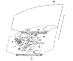
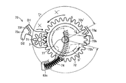
以下、本発明の第1実施形態について説明する。図1は、本実施形態に係るウィンドレギュレータ装置の全体構成を示す正面図である。このウィンドゥレギュレータ装置は車両のサイドウィンドウに設けられる窓ガラスを開閉する。図1に示されるようにウィンドレギュレータ装置は駆動機構1と駆動力伝達機構9を備える。駆動機構1は、動力源としての電気モータ2と、出力軸3と、電気モータ2に連結されたハウジング8と、ハウジング8に収容された図示しない検知ユニットを備える。電気モータ2は例えば車載バッテリなどの電源に電気的に接続され、電源からの電力供給により回転駆動力を発生する。出力軸3は電気モータ2が発生する回転駆動力により回転する。駆動力伝達機構9は、出力軸3の回転駆動力によって窓ガラスWが図の矢印により示される上下方向に開閉作動するように、出力軸3の回転駆動力を窓ガラスWに伝達する。ハウジング8内に収納された検知ユニットは、窓ガラスWの閉作動中に窓ガラスWと窓枠との間に異物が挟み込まれたか否か、および、窓ガラスWの開閉位置が予め定められている特定の開閉位置領域(特定位置領域)に属する位置であるか否か、を検知する。
(First embodiment)
The first embodiment of the present invention will be described below. FIG. 1 is a front view showing the overall configuration of the window regulator device according to the present embodiment. This window regulator device opens and closes a window glass provided on a side window of a vehicle. As shown in FIG. 1, the window regulator device includes a driving mechanism 1 and a driving force transmission mechanism 9. The drive mechanism 1 includes an electric motor 2 as a power source, an output shaft 3, a housing 8 connected to the electric motor 2, and a detection unit (not shown) housed in the housing 8. The electric motor 2 is electrically connected to a power source such as an in-vehicle battery, and generates a rotational driving force by supplying power from the power source. The output shaft 3 is rotated by the rotational driving force generated by the electric motor 2. The driving force transmission mechanism 9 transmits the rotational driving force of the output shaft 3 to the window glass W so that the window glass W is opened and closed by the rotational driving force of the output shaft 3 in the vertical direction indicated by the arrows in the figure. In the detection unit housed in the housing 8, whether or not a foreign object is caught between the window glass W and the window frame during the closing operation of the window glass W, and the opening / closing position of the window glass W are determined in advance. It is detected whether or not the position belongs to a specific opening / closing position area (specific position area).

図1に示されるように、駆動力伝達機構9は、固定ブラケット91,セクタギヤ92,リフトアーム93,第1ガイドレール部材94,第2ガイドレール部材95およびイコライザアーム96を備える。固定ブラケット91は車両のドアパネルに固定されているとともにハウジング8を支持している。セクタギヤ92は図に示されるように円弧状の歯部921を備え、この歯部921の円弧中心にてピン97により回転可能に固定ブラケット91に連結される。   As shown in FIG. 1, the driving force transmission mechanism 9 includes a fixed bracket 91, a sector gear 92, a lift arm 93, a first guide rail member 94, a second guide rail member 95, and an equalizer arm 96. The fixing bracket 91 is fixed to the door panel of the vehicle and supports the housing 8. The sector gear 92 includes an arcuate tooth portion 921 as shown in the figure, and is connected to the fixed bracket 91 so as to be rotatable by a pin 97 at the arc center of the tooth portion 921.

リフトアーム93は長尺状の部材であり先端に向けて先細りに形成される。リフトアーム93はその基端側にてセクタギヤ92の回転中心位置に固定される。したがって、セクタギヤ92がピン97の軸周りに回転すると、それに伴ってリフトアーム93もピン97を中心として同方向に回転する。また、リフトアーム93の先端にはシュー93aが連結される。   The lift arm 93 is a long member and is tapered toward the tip. The lift arm 93 is fixed to the rotation center position of the sector gear 92 on the base end side. Accordingly, when the sector gear 92 rotates around the axis of the pin 97, the lift arm 93 also rotates in the same direction around the pin 97. A shoe 93 a is connected to the tip of the lift arm 93.

第1ガイドレール部材94は窓ガラスWの下部にほぼ水平にに固定される。第1ガイドレール部材94には、その長手方向に沿ってガイド溝が形成される。このガイド溝内にシュー93aが摺動可能に配設される。第2ガイドレール部材95はドアパネルに固定される。第2ガイドレール部材95にも、その長手方向に沿ってガイド溝が形成される。   The first guide rail member 94 is fixed substantially horizontally to the lower part of the window glass W. A guide groove is formed in the first guide rail member 94 along its longitudinal direction. A shoe 93a is slidably disposed in the guide groove. The second guide rail member 95 is fixed to the door panel. A guide groove is also formed in the second guide rail member 95 along its longitudinal direction.

イコライザアーム96は第1アーム961および第2アーム962を備える。第1アーム961および第2アーム962はいずれも長尺状の部材である。両アームの基端側同士がリフトアーム93の略中央付近にて結合される。第1アーム961および第2アーム962は結合状態にて図の方向から見て同一の軸を持つように直線状に各々固定され、かつリフトアーム93の中心付近で回転可能にリフトアーム93に連結される。また、第1アーム961の先端にはシュー961aが連結される。このシュー961aは第1ガイドレール部材94のガイド溝内に摺動可能に配設される。第2アーム962の先端にもシューが連結され、このシューは第2ガイドレール部材95のガイド溝内に摺動可能に配設される。したがって、第1ガイドレール部材94のガイド溝にはリフトアーム93の先端および第1アーム961の先端が、第2ガイドレール部材95のガイド溝には第2アーム962の先端が、それぞれシューを介して連結される。また、第1ガイドレール部材94と第2ガイドレール部材95が平行に配置するように、各アーム寸法が調整される。   The equalizer arm 96 includes a first arm 961 and a second arm 962. The first arm 961 and the second arm 962 are both long members. The base end sides of both arms are coupled in the vicinity of the approximate center of the lift arm 93. The first arm 961 and the second arm 962 are linearly fixed so as to have the same axis when viewed from the direction in the figure in the coupled state, and are connected to the lift arm 93 so as to be rotatable near the center of the lift arm 93. Is done. A shoe 961 a is connected to the tip of the first arm 961. The shoe 961 a is slidably disposed in the guide groove of the first guide rail member 94. A shoe is also connected to the tip of the second arm 962, and this shoe is slidably disposed in the guide groove of the second guide rail member 95. Therefore, the tip of the lift arm 93 and the tip of the first arm 961 are inserted into the guide groove of the first guide rail member 94, and the tip of the second arm 962 is inserted into the guide groove of the second guide rail member 95 via the shoe. Connected. Also, the arm dimensions are adjusted so that the first guide rail member 94 and the second guide rail member 95 are arranged in parallel.

出力軸3はハウジング8に回転可能に支持される。この出力軸3は電気モータ2の回転駆動力を受けて回転する。また後述するように、出力軸3には出力ギヤ部が形成されており、この出力ギヤ部はセクタギヤ92の歯部921に噛み合う。   The output shaft 3 is rotatably supported by the housing 8. The output shaft 3 receives the rotational driving force of the electric motor 2 and rotates. As will be described later, an output gear portion is formed on the output shaft 3, and this output gear portion meshes with a tooth portion 921 of the sector gear 92.

このような構成において、出力軸3が図1において時計回り方向に回転すると、その回転はセクタギヤ92に伝達されて、セクタギヤ92がピン97を中心に反時計回り方向に回転する。これに伴いリフトアーム93もピン97を中心に反時計回り方向に回転する。リフトアーム93が反時計周り方向に回転すると、リフトアーム93の先端に取り付けられたシュー93aが図の一点鎖線で示されたような円弧状の軌跡を描くため、シュー93aが第1ガイドレール部材94のガイド溝内を摺動するとともに第1ガイドレール部材94が上方移動する。これに伴い窓ガラスWが上方移動する。つまり窓ガラスWが閉作動する。窓ガラスWの閉作動時には、イコライザアーム96がリフトアーム93,第1ガイドレール部材94および第2ガイドレール部材95との間の構造的配置関係を維持するように回転する。これにより第1ガイドレール部材94が第2ガイドレール部材95との間の平行状態を維持しながら上昇する。   In such a configuration, when the output shaft 3 rotates clockwise in FIG. 1, the rotation is transmitted to the sector gear 92, and the sector gear 92 rotates counterclockwise around the pin 97. Along with this, the lift arm 93 also rotates counterclockwise around the pin 97. When the lift arm 93 rotates in the counterclockwise direction, the shoe 93a attached to the tip of the lift arm 93 draws an arcuate locus as indicated by a one-dot chain line in the drawing, so that the shoe 93a becomes the first guide rail member. The first guide rail member 94 moves upward while sliding in the guide groove 94. Accordingly, the window glass W moves upward. That is, the window glass W is closed. When the window glass W is closed, the equalizer arm 96 rotates to maintain the structural arrangement relationship between the lift arm 93, the first guide rail member 94, and the second guide rail member 95. As a result, the first guide rail member 94 rises while maintaining a parallel state with the second guide rail member 95.

また、出力軸3が図1において反時計回り方向に回転すると、セクタギヤ92がピン97を中心として時計回り方向に回転する。これに伴いリフトアーム93もピン97を中心として時計回り方向に回転する。これによりシュー93aが第1ガイドレール部材94のガイド溝内を摺動するとともに第1ガイドレール部材94が下方移動する。第1ガイドレール部材94の下方移動により窓ガラスWも下方移動する。つまり窓ガラスWが開方向に作動(開作動)する。窓ガラスWの開作動時には、イコライザアーム96がリフトアーム93,第1ガイドレール部材94および第2ガイドレール部材95との間の構造的配置関係を維持するように回転する。これにより第1ガイドレール部材94が第2ガイドレール部材95との間の平行状態を維持しながら下降する。このようにして窓ガラスWの開閉が行われる。なお、図において実線で示された窓ガラスWの開閉位置が全閉位置であり、二点鎖線で示された窓ガラスWの開閉位置が全開位置である。   When the output shaft 3 rotates in the counterclockwise direction in FIG. 1, the sector gear 92 rotates in the clockwise direction around the pin 97. Along with this, the lift arm 93 also rotates clockwise about the pin 97. Accordingly, the shoe 93a slides in the guide groove of the first guide rail member 94 and the first guide rail member 94 moves downward. As the first guide rail member 94 moves downward, the window glass W also moves downward. That is, the window glass W operates in the opening direction (opening operation). When the window glass W is opened, the equalizer arm 96 rotates so as to maintain the structural arrangement relationship between the lift arm 93, the first guide rail member 94, and the second guide rail member 95. As a result, the first guide rail member 94 is lowered while maintaining a parallel state with the second guide rail member 95. In this way, the window glass W is opened and closed. In the figure, the open / close position of the window glass W indicated by a solid line is a fully closed position, and the open / close position of the window glass W indicated by a two-dot chain line is a fully open position.

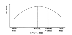
上記のように作動するアーム式の駆動力伝達機構9を備えるウィンドレギュレータ装置においては、リフトアーム93の回転運動が窓ガラスWの直線運動に変換される。したがって、窓ガラスWの閉作動時に窓ガラスWの荷重により出力軸3に作用するモーメントがリフトアーム93の回転位置により変化する。図2は、窓ガラスWが全開位置から全閉位置まで閉作動するときに出力軸3に作用するモーメントの大きさと、リフトアーム93の回転位置との関係を示したグラフである。このグラフからわかるように、リフトアーム93の回転位置が重力方向に直交する水平位置であるときにモーメントが最大である。リフトアーム93の回転位置が水平位置から上死点位置(窓ガラスWの全閉位置)または下死点位置(窓ガラスの全開位置)に向かうほどモーメントが小さくなる。   In the window regulator device including the arm-type driving force transmission mechanism 9 that operates as described above, the rotational motion of the lift arm 93 is converted into the linear motion of the window glass W. Therefore, the moment acting on the output shaft 3 due to the load on the window glass W during the closing operation of the window glass W varies depending on the rotational position of the lift arm 93. FIG. 2 is a graph showing the relationship between the magnitude of the moment acting on the output shaft 3 and the rotational position of the lift arm 93 when the window glass W is closed from the fully open position to the fully closed position. As can be seen from this graph, the moment is maximum when the rotational position of the lift arm 93 is a horizontal position orthogonal to the direction of gravity. The moment decreases as the rotational position of the lift arm 93 moves from the horizontal position toward the top dead center position (the fully closed position of the window glass W) or the bottom dead center position (the fully opened position of the window glass).

図3は駆動機構1の分解斜視図である。図に示されるように、駆動機構1は、電気モータ2と、出力軸3と、検知ユニット5と、ハウジング8を備える。電気モータ2は図示しない締結手段などによりハウジング8に連結される。ハウジング8は、第1ハウジング81と、第2ハウジング82と、第3ハウジング83と、蓋84を備える。第1ハウジング81は軸方向に長い円筒形状に形成されており、内部には電気モータ2のモータ軸に連結された図示しないウォームが収納される。このウォームはモータ軸と同軸回転する。第2ハウジング82は第1ハウジング81の側周部に隣接し、第1ハウジング81の円筒軸と直交する軸を持つ円筒形状をなし、上端側が開口している。なお、第1ハウジング81の内部空間と第2ハウジング82の内部空間は、両ハウジングの隣接部位にて連通する。   FIG. 3 is an exploded perspective view of the drive mechanism 1. As shown in the figure, the drive mechanism 1 includes an electric motor 2, an output shaft 3, a detection unit 5, and a housing 8. The electric motor 2 is connected to the housing 8 by fastening means (not shown). The housing 8 includes a first housing 81, a second housing 82, a third housing 83, and a lid 84. The first housing 81 is formed in a long cylindrical shape in the axial direction, and a worm (not shown) connected to the motor shaft of the electric motor 2 is accommodated therein. This worm rotates coaxially with the motor shaft. The second housing 82 is adjacent to the side periphery of the first housing 81, has a cylindrical shape having an axis orthogonal to the cylindrical axis of the first housing 81, and has an upper end opened. The internal space of the first housing 81 and the internal space of the second housing 82 communicate with each other at adjacent portions of both housings.

第3ハウジング83は第2ハウジング82の上部に配置形成される。この第3ハウジング83は、第2ハウジング82の上端開口縁から図において右方向に略水平に拡がった底面83aと、底面83aの周縁から立設した側壁83bを持つ。したがって図からわかるように、第3ハウジング83の底面83aから窪んでいる円形状の空間Sが第2ハウジング82内の空間である。第3ハウジング83の上端は開口しており、この開口は蓋84により塞がれる。蓋84は図示しない締結手段により第3ハウジング83に固定される。第3ハウジング83内には、後述する抑えバネ74を収納する抑えバネ収納用隔壁83cが、空間Sに沿って円弧状に形成される。   The third housing 83 is disposed and formed on the second housing 82. The third housing 83 has a bottom surface 83a extending substantially horizontally in the right direction from the upper end opening edge of the second housing 82, and a side wall 83b erected from the periphery of the bottom surface 83a. Therefore, as can be seen from the figure, a circular space S that is recessed from the bottom surface 83 a of the third housing 83 is a space in the second housing 82. The upper end of the third housing 83 is open, and this opening is closed by the lid 84. The lid 84 is fixed to the third housing 83 by fastening means (not shown). In the third housing 83, a retaining spring accommodating partition wall 83c for accommodating a retaining spring 74 described later is formed in an arc shape along the space S.

図に示されるように第2ハウジング82の底面中央部分には円筒状のボス82aが形成されている。このボス82a内の円孔に出力軸3が挿通する。出力軸3は第2ハウジング82および第3ハウジング83の内部空間に進入する。出力軸3は先端部31および基端部32を有し、基端部32から先端部31にかけて出力ギヤ部33,軸部34,係合部35がこの順に形成されている。出力ギヤ部33は上述したように駆動力伝達機構9のセクタギヤ92に噛み合い、出力軸3の回転駆動力を駆動力伝達機構9に伝達する。係合部35は断面略十字状に形成され、後述する被駆動プレート63に嵌合する。軸部34、係合部35および先端部31が第2ハウジング82および第3ハウジング83の内部空間に進入する。先端部31が蓋84の内側面(ハウジング8の内部空間に向いた面)に形成されている凹部84aに挿入される。これにより出力軸3がハウジング8に回転可能且つ軸方向移動不能に支持される。   As shown in the drawing, a cylindrical boss 82 a is formed at the center of the bottom surface of the second housing 82. The output shaft 3 is inserted through the circular hole in the boss 82a. The output shaft 3 enters the internal space of the second housing 82 and the third housing 83. The output shaft 3 has a distal end portion 31 and a proximal end portion 32, and an output gear portion 33, a shaft portion 34, and an engaging portion 35 are formed in this order from the proximal end portion 32 to the distal end portion 31. As described above, the output gear portion 33 meshes with the sector gear 92 of the driving force transmission mechanism 9 and transmits the rotational driving force of the output shaft 3 to the driving force transmission mechanism 9. The engaging portion 35 is formed in a substantially cross-shaped cross section and is fitted to a driven plate 63 described later. The shaft portion 34, the engaging portion 35, and the tip portion 31 enter the internal spaces of the second housing 82 and the third housing 83. The distal end portion 31 is inserted into a concave portion 84 a formed on the inner side surface of the lid 84 (the surface facing the inner space of the housing 8). As a result, the output shaft 3 is supported by the housing 8 so as to be rotatable and immovable in the axial direction.

ハウジング8内に収納される検知ユニット5は、挟み込み検知ユニット6および位置検知ユニット7からなる。挟み込み検知ユニット6は第2ハウジング82内に配設される。挟み込み検知ユニット6は、ウォームホイール61、駆動力伝達バネ62、被駆動プレート63、ワッシャ64、挟み込み検知プレート65、挟み込み検知スイッチ66および板バネ67を備える。   The detection unit 5 housed in the housing 8 includes a pinching detection unit 6 and a position detection unit 7. The pinching detection unit 6 is disposed in the second housing 82. The pinching detection unit 6 includes a worm wheel 61, a driving force transmission spring 62, a driven plate 63, a washer 64, a pinching detection plate 65, a pinching detection switch 66, and a leaf spring 67.

ウォームホイール61は第2ハウジング82の内部空間Sの図において最も下部に配置される。ウォームホイール61は、円筒形状をなし外周側に歯(例えばはすば歯)が形成された外周壁部61aと、内周に円孔61bが形成された円筒形状の内周壁部61cと、外周壁部61aの下端と内周壁部61cの下端とを連結するリング状の底面部61dを有する。第2ハウジング82のボス82aが円孔61bに嵌め込まれることにより、ウォームホイール61が第2ハウジング82に回転可能に支持される。円孔61bには出力軸3が挿通される。また、外周壁部61aに形成された歯が第1ハウジング81内に収容されているウォームと噛み合う。このウォームホイール61とウォームによりウォーム減速ギヤが構成される。したがって、ウォームが回転するとその回転がウォームホイール61に伝達されて、ウォームホイール61が出力軸3を中心軸として減速回転する。   The worm wheel 61 is disposed at the lowermost position in the drawing of the internal space S of the second housing 82. The worm wheel 61 has a cylindrical shape and an outer peripheral wall portion 61a in which teeth (for example, helical teeth) are formed on the outer peripheral side, a cylindrical inner peripheral wall portion 61c in which a circular hole 61b is formed in the inner periphery, A ring-shaped bottom surface portion 61d that connects the lower end of the wall portion 61a and the lower end of the inner peripheral wall portion 61c is provided. When the boss 82a of the second housing 82 is fitted into the circular hole 61b, the worm wheel 61 is rotatably supported by the second housing 82. The output shaft 3 is inserted through the circular hole 61b. Further, teeth formed on the outer peripheral wall portion 61 a mesh with a worm housed in the first housing 81. The worm wheel 61 and the worm constitute a worm reduction gear. Therefore, when the worm rotates, the rotation is transmitted to the worm wheel 61, and the worm wheel 61 rotates at a reduced speed with the output shaft 3 as the central axis.

ウォームホイール61内に係止部611が形成される。この係止部611は底面部61dから立設され、その高さは外周壁部61aの高さを上回る。また、外周壁部61aの上端面には周方向に沿って凸状に形成された複数個(本実施形態では4個)の突片612が等間隔に設けられる。各突片612は外周壁部61aに沿った円弧形状をなし、一方の端部は図に示されるようにテーパ状に形成される。   A locking portion 611 is formed in the worm wheel 61. The locking portion 611 is erected from the bottom surface portion 61d, and the height thereof exceeds the height of the outer peripheral wall portion 61a. A plurality (four in the present embodiment) of projecting pieces 612 formed in a convex shape along the circumferential direction are provided at equal intervals on the upper end surface of the outer peripheral wall 61a. Each projecting piece 612 has an arc shape along the outer peripheral wall 61a, and one end is formed in a tapered shape as shown in the figure.

駆動力伝達バネ62は、ウォームホイール61の底面部61d上に配設される。駆動力伝達バネ62は底面部61dに沿うように円弧状に形成され、その一端にて係止部611に係止される。   The driving force transmission spring 62 is disposed on the bottom surface portion 61 d of the worm wheel 61. The driving force transmission spring 62 is formed in an arc shape along the bottom surface portion 61d, and is locked to the locking portion 611 at one end thereof.

被駆動プレート63は周方向の一部分が扇形状に切りかかれたような略円板形状をなし、切りかかれている部分を境にして径の大きい大径部63bおよび径の小さい小径部63cを有する。この被駆動プレート63の中央部に十字状の貫通孔63aが形成される。十字状の貫通孔63aに出力軸3の係合部35が嵌め込まれる。これにより被駆動プレート63は出力軸3に一体回転可能に連結される。また被駆動プレート63は、その上部に配置されたワッシャ64により軸方向移動が規制される。このような形状を有する被駆動プレート63が第2ハウジング82内にてウォームホイール61上に同軸的に配設される。このときウォームホイール61に形成されている係止部611が、被駆動プレート63の扇形状に切り欠かれた部分により形成される空隙から突出することで、係止部611と被駆動プレート63との干渉が防止される。また、大径部63bの周方向端部(切り欠き端部)の一方から図において下方に延びた第1突片63dが、他方から図において上方に延びた第2突片63eが、それぞれ形成される。第1突片63dにはウォームホイール61内に配設された駆動力伝達バネ62の他端が係止される。したがって、駆動力伝達バネ62は、その一端にてウォームホイール61の係止部611に、他端にて被駆動プレート63の第1突片63dに、それぞれ係止される。また、被駆動プレート63の大径部63bには、図に示されるように周方向に沿って延びた円弧状の長孔63fが形成される。   The driven plate 63 has a substantially disk shape in which a part in the circumferential direction is cut into a fan shape, and has a large-diameter portion 63b having a large diameter and a small-diameter portion 63c having a small diameter with the cut portion as a boundary. . A cross-shaped through hole 63 a is formed at the center of the driven plate 63. The engaging portion 35 of the output shaft 3 is fitted into the cross-shaped through hole 63a. Thereby, the driven plate 63 is connected to the output shaft 3 so as to be integrally rotatable. In addition, the driven plate 63 is restricted from moving in the axial direction by a washer 64 disposed above the driven plate 63. The driven plate 63 having such a shape is coaxially disposed on the worm wheel 61 in the second housing 82. At this time, the locking portion 611 formed on the worm wheel 61 protrudes from the gap formed by the fan-shaped portion of the driven plate 63 so that the locking portion 611 and the driven plate 63 are Interference is prevented. Further, a first projecting piece 63d extending downward in the drawing from one of the circumferential end portions (notched end portions) of the large-diameter portion 63b and a second projecting piece 63e extending upward in the drawing from the other are formed, respectively. Is done. The other end of the driving force transmission spring 62 disposed in the worm wheel 61 is locked to the first protrusion 63d. Therefore, the driving force transmission spring 62 is locked to the locking portion 611 of the worm wheel 61 at one end and to the first protruding piece 63d of the driven plate 63 at the other end. The large-diameter portion 63b of the driven plate 63 is formed with an arc-shaped elongated hole 63f extending along the circumferential direction as shown in the figure.

挟み込み検知プレート65は、段付き円板形状の回転板651と、回転板651の図において下面の外周縁付近に周方向に沿って凸状に形成され、等間隔に設けられた複数の突片652とを備える。回転板651の中央には出力軸3を挿通する円孔が形成される。また、回転板651の下面側に断面円弧状の凸部651aが形成される。この凸部651aは被駆動プレート63に形成された長孔63fと同形状の断面を有する。凸部651aが長孔63fに嵌め込まれるように挟み込み検知プレート65が被駆動プレート63上に同軸的に載置される。これにより挟み込み検知プレート65が被駆動プレート63に一体回転可能且つ軸方向移動可能に連結され、両プレートは出力軸3を中心軸として一体的に回転する。   The pinching detection plate 65 includes a stepped disk-shaped rotating plate 651 and a plurality of projecting pieces formed in a convex shape along the circumferential direction in the vicinity of the outer peripheral edge of the lower surface of the rotating plate 651 in the figure. 652. A circular hole through which the output shaft 3 is inserted is formed at the center of the rotating plate 651. In addition, a convex portion 651 a having a circular arc cross section is formed on the lower surface side of the rotating plate 651. The convex portion 651 a has a cross section having the same shape as the long hole 63 f formed in the driven plate 63. The pinching detection plate 65 is coaxially mounted on the driven plate 63 so that the convex portion 651a is fitted into the long hole 63f. As a result, the pinching detection plate 65 is connected to the driven plate 63 so as to be integrally rotatable and axially movable, and both plates rotate integrally around the output shaft 3 as a central axis.

また、回転板651には、周方向に沿って円弧状の長孔651bが形成される。挟み込み検知ユニット6が第2ハウジング82内に収納されたとき、この長孔651bから被駆動プレート63に形成された第2突片63eおよびウォームホイール61に形成された係止部611が突出する。   Further, the rotary plate 651 is formed with an arc-shaped long hole 651b along the circumferential direction. When the pinching detection unit 6 is housed in the second housing 82, the second protrusion 63e formed on the driven plate 63 and the locking portion 611 formed on the worm wheel 61 project from the long hole 651b.

複数の突片652は回転板651の中心からの径方向距離が同一となるように回転板651の周方向に沿って設けられる。各突片652は回転板651の周方向に沿った円弧形状をなし、長手方向の一方の端面がテーパ状である。突片652の個数はウォームホイール61の外周壁部61aに形成されている突片612の個数と同じ(本実施形態では4個)である。回転板651の中心から各突片652までの径方向距離は、ウォームホイール61の中心からその外周壁部61aに形成された各突片612までの径方向距離と同じである。したがって、挟み込み検知プレート65と被駆動プレート63との組み付け体がウォームホイール61上に載置されたときに、各突片652はウォームホイール61の外周壁部61aの上端面に対面する。そして、ウォームホイール61と挟み込み検知プレート65が出力軸3を中心に回転した場合には、突片652と突片612が同一円周上を回転する。また、ウォームホイール61と挟み込み検知プレート65が相対回転した場合には、突片612と突片652が干渉する。この場合において、ウォームホイール61が図の矢印X方向に回転し、挟み込み検知プレート65が回転していないときに両突片612,652が干渉した場合には、両突片612,652のテーパ面が係合することにより相対回転が許容されるとともに挟み込み検知プレート65が押し上げられる。   The plurality of protruding pieces 652 are provided along the circumferential direction of the rotating plate 651 so that the radial distance from the center of the rotating plate 651 is the same. Each protrusion 652 has an arc shape along the circumferential direction of the rotating plate 651, and one end face in the longitudinal direction is tapered. The number of projecting pieces 652 is the same as the number of projecting pieces 612 formed on the outer peripheral wall 61a of the worm wheel 61 (four in this embodiment). The radial distance from the center of the rotating plate 651 to each protruding piece 652 is the same as the radial distance from the center of the worm wheel 61 to each protruding piece 612 formed on the outer peripheral wall portion 61a. Therefore, when the assembly of the pinching detection plate 65 and the driven plate 63 is placed on the worm wheel 61, each projecting piece 652 faces the upper end surface of the outer peripheral wall portion 61a of the worm wheel 61. When the worm wheel 61 and the pinching detection plate 65 rotate around the output shaft 3, the projecting piece 652 and the projecting piece 612 rotate on the same circumference. Further, when the worm wheel 61 and the pinching detection plate 65 are relatively rotated, the projecting piece 612 interferes with the projecting piece 652. In this case, if both the projecting pieces 612 and 652 interfere when the worm wheel 61 rotates in the direction of the arrow X in the drawing and the pinching detection plate 65 does not rotate, the tapered surfaces of the both projecting pieces 612 and 652 Engagement allows the relative rotation and pushes up the pinching detection plate 65.

板バネ67はリング状の部分とこのリング状の部分から放射状に延びた板状の部分を有し、リング状の部分に出力軸3が挿通される。板バネ67は挟み込み検知プレート65と後述する作動レバー73との間に介在する。したがって挟み込み検知プレート65は板バネ67の弾性力を受け、ワッシャ64を介して被駆動プレート63に押し付けられる。   The leaf spring 67 has a ring-shaped portion and a plate-shaped portion extending radially from the ring-shaped portion, and the output shaft 3 is inserted through the ring-shaped portion. The leaf spring 67 is interposed between the pinching detection plate 65 and an operating lever 73 described later. Therefore, the pinching detection plate 65 receives the elastic force of the leaf spring 67 and is pressed against the driven plate 63 via the washer 64.

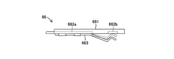
図4は、挟み込み検知スイッチ66の側面概略図である。図からわかるように挟み込み検知スイッチ66は、基板661と、基板661上に形成された第1導電部662aおよび第2導電部662bと、一端が第1導電部662aに接続された可動片663を有する。可動片663の先端が実線で示されているように基板661から離間しているときは、第1導電部662aと第2導電部662bが非導通状態である。一方、可動片663の先端が押圧されて破線で示されているように基板661上の第2導電部662bに接触した場合に可動片663を介して第1導電部662aと第2導電部662bが導通状態になる。第1導電部662aと第2導電部662bが非導通状態であるときは、挟み込み検知スイッチ66の切り換え状態がOFF状態であり、導通状態であるときは、挟み込み検知スイッチ66の切り換え状態がON状態である。   FIG. 4 is a schematic side view of the pinching detection switch 66. As can be seen, the pinch detection switch 66 includes a substrate 661, a first conductive portion 662a and a second conductive portion 662b formed on the substrate 661, and a movable piece 663 having one end connected to the first conductive portion 662a. Have. When the tip of the movable piece 663 is separated from the substrate 661 as indicated by a solid line, the first conductive portion 662a and the second conductive portion 662b are in a non-conductive state. On the other hand, when the tip of the movable piece 663 is pressed and comes into contact with the second conductive portion 662b on the substrate 661 as indicated by a broken line, the first conductive portion 662a and the second conductive portion 662b are interposed via the movable piece 663. Becomes conductive. When the first conductive portion 662a and the second conductive portion 662b are in a non-conductive state, the switching state of the pinch detection switch 66 is in an OFF state. When the first conductive portion 662a and the second conductive portion 662b are in a conductive state, the switching state of the pinch detection switch 66 is in an ON state. It is.

挟み込み検知スイッチ66は、その可動片663が挟み込み検知プレート65に面するように挟み込み検知プレート65の図3において直上に配置され、図示しない固定手段によりその位置が固定されている。したがって、挟み込み検知プレート65の上下動により挟み込み検知スイッチ66の切り換え状態が変化する。挟み込み検知スイッチ66は蓋84の内面側に形成されていてもよい。   The pinch detection switch 66 is disposed immediately above the pinch detection plate 65 in FIG. 3 so that the movable piece 663 faces the pinch detection plate 65, and its position is fixed by a fixing means (not shown). Accordingly, the switching state of the pinching detection switch 66 is changed by the vertical movement of the pinching detection plate 65. The pinching detection switch 66 may be formed on the inner surface side of the lid 84.

なお、ウォームとウォームホイール61との噛合面には通常グリースなどの潤滑剤が塗布されるが、このグリースの飛散を防止するために、飛散防止プレート4が設けられる。この飛散防止プレート4は、第3ハウジング83の底面83a上の第2ハウジング82内の空間Sを取り囲む位置に載置される。   Note that a lubricant such as grease is usually applied to the meshing surface between the worm and the worm wheel 61, but a scattering prevention plate 4 is provided to prevent the grease from scattering. The scattering prevention plate 4 is placed at a position surrounding the space S in the second housing 82 on the bottom surface 83 a of the third housing 83.

図5は、各部品が組み付けられた挟み込み検知ユニット6の正面図であり、図6は図5のA−A断面図である。図5からわかるように、ウォームホイール61は第1ハウジング81に収納されたウォームWGに噛み合う。ウォームホイール61が図のX方向(このX方向は図3のX方向と同一方向である。)に回転したときに、ウォームホイール61に形成された係止部611によって一端が係止された駆動力伝達バネ62がX方向に押圧されるとともに、第1突片63dにて駆動力伝達バネ62の他端を係止した被駆動プレート63が駆動力伝達バネ62によりX方向に押圧される。   FIG. 5 is a front view of the pinching detection unit 6 in which each component is assembled, and FIG. 6 is a cross-sectional view taken along line AA in FIG. As can be seen from FIG. 5, the worm wheel 61 meshes with the worm WG housed in the first housing 81. Drive with one end locked by a locking portion 611 formed on the worm wheel 61 when the worm wheel 61 rotates in the X direction in the figure (the X direction is the same as the X direction in FIG. 3). The force transmission spring 62 is pressed in the X direction, and the driven plate 63 that is engaged with the other end of the driving force transmission spring 62 by the first protrusion 63 d is pressed in the X direction by the driving force transmission spring 62.

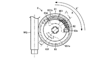
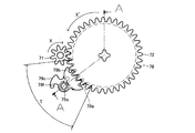
位置検知ユニット7は本発明の開閉位置検知手段に相当する。位置検知ユニット7は第3ハウジング83内に配設される。図3に示されるように、位置検知ユニット7は、第1歯車71と、第2歯車72と、作動レバー73と、抑えバネ74と、不感帯領域検知スイッチ75と、反転作動領域検知スイッチ76と、連結ピン77と、第3ハウジング83に取り付けられたストッパ73gとを備える。第1歯車71の中央には円孔が形成される。この円孔に出力軸3が嵌め込まれることにより、第1歯車71が出力軸3に一体回転可能に支持される。第2歯車72は第1歯車71と噛み合う位置に配置される。図からわかるように第2歯車72の歯数は第1歯車71の歯数よりも多い。したがって、第2歯車72は第1歯車71の回転を減速する。また、第2歯車72の図において上面に凸状のカム72aが形成される。このカム72aは第2歯車72の周方向に沿って所定の長さを持ち、周方向に沿って円弧状に形成される。また、第2歯車72の図において下面に円柱状の凸部72bが形成される。この凸部72bは、本発明において作動レバー73に係合可能な係合部材に相当する。また、第2歯車72の中心には円孔が形成され、この円孔内に連結ピン77が挿通される。連結ピン77により第2歯車72が回転可能に支持される。   The position detection unit 7 corresponds to the opening / closing position detection means of the present invention. The position detection unit 7 is disposed in the third housing 83. As shown in FIG. 3, the position detection unit 7 includes a first gear 71, a second gear 72, an operation lever 73, a restraining spring 74, a dead band region detection switch 75, and a reverse operation region detection switch 76. The connecting pin 77 and a stopper 73g attached to the third housing 83 are provided. A circular hole is formed in the center of the first gear 71. By fitting the output shaft 3 into the circular hole, the first gear 71 is supported by the output shaft 3 so as to be integrally rotatable. The second gear 72 is disposed at a position that meshes with the first gear 71. As can be seen, the number of teeth of the second gear 72 is greater than the number of teeth of the first gear 71. Therefore, the second gear 72 decelerates the rotation of the first gear 71. Further, a convex cam 72 a is formed on the upper surface in the drawing of the second gear 72. The cam 72a has a predetermined length along the circumferential direction of the second gear 72, and is formed in an arc shape along the circumferential direction. Further, in the drawing of the second gear 72, a cylindrical convex portion 72b is formed on the lower surface. This convex part 72b is corresponded to the engaging member which can be engaged with the action | operation lever 73 in this invention. A circular hole is formed at the center of the second gear 72, and the connecting pin 77 is inserted into the circular hole. The second gear 72 is rotatably supported by the connecting pin 77.

作動レバー73は第1歯車71および第2歯車72の図において下方に配設され、細長い平板形状を呈する。図7は作動レバー73の正面図である。図からわかるように、作動レバー73には出力軸3が挿通する第1円孔73aが形成されている。第1円孔73aに出力軸3が挿通することにより作動レバー73が出力軸3に相対回転可能に支持される。なお出力軸3は、第1円孔73aを挿通した後に第1歯車71に形成された円孔を挿通する。   The operating lever 73 is disposed below the first gear 71 and the second gear 72 in the figure, and has an elongated flat plate shape. FIG. 7 is a front view of the operating lever 73. As can be seen from the figure, the operating lever 73 is formed with a first circular hole 73a through which the output shaft 3 is inserted. When the output shaft 3 is inserted into the first circular hole 73a, the operating lever 73 is supported by the output shaft 3 so as to be relatively rotatable. The output shaft 3 is inserted through the circular hole formed in the first gear 71 after passing through the first circular hole 73a.

また、作動レバー73は、第1円孔73aから長手方向の一方側(図の右方側)に延びた第1アーム部73bおよび他方側(図の左方側)に延びた第2アーム部73cを有する。第1アーム部73bの略中央に第2円孔73dが形成される。第2円孔73d内には、第2歯車72を挿通した連結ピン77が挿通される。この連結ピン77を介して作動レバー73が第2歯車72に連結される。したがって、作動レバー73は、第1歯車71と一体回転する出力軸3に相対回転可能に支持されているとともに、連結ピン77を介して第2歯車72に連結される。第2歯車72は図に示されるように作動レバー73の第1アーム部73bの直上位置に回転可能に配置される。この場合において、第1アーム部73bは、第2歯車72が回転したときに第2歯車72の下面に形成された凸部72bが第1アーム部73bの先端部分Aに係合し且つ基端部分Bに係合しないように、起伏を持って形成される。また、第1アーム部73bには係止部73eが形成される。この係止部73eは後述する抑えバネ74の一端を係止する。また、第2アーム部73cの先端部分には段差73fが形成される。第1円孔73aの軸方向を高さ方向とした場合、この段差73fを挟んだ一方の部分D1の高さと他方の部分D2の高さは異なっている。   The actuating lever 73 includes a first arm portion 73b extending from the first circular hole 73a to one side in the longitudinal direction (right side in the drawing) and a second arm portion extending to the other side (left side in the drawing). 73c. A second circular hole 73d is formed in the approximate center of the first arm portion 73b. A connecting pin 77 through which the second gear 72 is inserted is inserted into the second circular hole 73d. The operating lever 73 is connected to the second gear 72 through the connecting pin 77. Therefore, the operating lever 73 is supported by the output shaft 3 that rotates integrally with the first gear 71 so as to be relatively rotatable, and is connected to the second gear 72 via the connecting pin 77. As shown in the drawing, the second gear 72 is rotatably disposed at a position immediately above the first arm portion 73b of the operating lever 73. In this case, in the first arm portion 73b, the convex portion 72b formed on the lower surface of the second gear 72 is engaged with the distal end portion A of the first arm portion 73b when the second gear 72 rotates, and the proximal end. It is formed with undulations so as not to engage with the portion B. Further, a locking portion 73e is formed on the first arm portion 73b. The locking portion 73e locks one end of a later-described holding spring 74. Further, a step 73f is formed at the tip of the second arm portion 73c. When the axial direction of the first circular hole 73a is the height direction, the height of one portion D1 across the step 73f is different from the height of the other portion D2.

抑えバネ74は、第3ハウジング83内に形成されている抑えバネ収納用隔壁83c内に収納される。図3に示されるように抑えバネ収納用隔壁83cは、同心状に形成された二つの円弧状の壁と、これらの円弧状の壁の一端側を塞ぐ底壁により形成され、他端側が開口している。このような抑えバネ収納用隔壁83c内に収納された抑えバネ74の一端が上記したように作動レバー73の係止部73eに係止され、他端が抑えバネ収納用隔壁83cの底壁に係止される。したがって作動レバー73は抑えバネ74が発生する伸張力により付勢されて第1円孔73aを中心として回転しようとするが、この回転は、第3ハウジング83内に設けられているストッパ73gに作動レバー73の第1アーム部73bの先端部分が係合することにより規制される。この規制によって作動レバー73が位置決めされる。   The holding spring 74 is stored in a holding spring storage partition wall 83 c formed in the third housing 83. As shown in FIG. 3, the holding spring accommodating partition wall 83c is formed by two concentric arc-shaped walls and a bottom wall that closes one end side of these arc-shaped walls, and the other end side is open. is doing. One end of the holding spring 74 housed in such a holding spring storage partition wall 83c is locked to the locking portion 73e of the operating lever 73 as described above, and the other end is fixed to the bottom wall of the holding spring storage partition wall 83c. Locked. Therefore, the operating lever 73 is urged by the extension force generated by the restraining spring 74 and tries to rotate around the first circular hole 73a. This rotation is applied to the stopper 73g provided in the third housing 83. It is regulated by the engagement of the tip end portion of the first arm portion 73b of the lever 73. The operation lever 73 is positioned by this restriction.

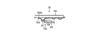
図8は不感帯領域検知スイッチ75の側面概略図、図9は反転作動領域検知スイッチ76の側面概略図である。これらのスイッチ75,76は挟み込み検知スイッチ66と同様に、基板751,761と、基板751,761上に形成された第1導電部752a,762aおよび第2導電部752b,762bと、一端が第1導電部752a,762aに接続された可動片753,763を有する。可動片753,763の先端が実線で示されているように基板751,761から離間しているときは、第1導電部752a,762aと第2導電部752b,762bが非導通状態である。一方、可動片753,763の先端が押圧されて破線で示されているように基板751,761上の第2導電部752b,762bに接触した場合に第1導電部752a,762aと第2導電部752b,762bが導通状態になる。第1導電部752a,762aと第2導電部752b,762bが非導通状態であるときは、これらのスイッチ75,76の切り換え状態がOFF状態であり、導通状態であるときは、これらのスイッチ75,76の切り換え状態がON状態である。   FIG. 8 is a schematic side view of the dead zone detection switch 75, and FIG. 9 is a schematic side view of the reverse operation region detection switch 76. Similar to the pinch detection switch 66, these switches 75 and 76 have substrates 751 and 761, first conductive portions 752a and 762a and second conductive portions 752b and 762b formed on the substrates 751 and 761, and one ends of the switches 75 and 76. It has movable pieces 753 and 763 connected to one conductive portion 752a and 762a. When the tips of the movable pieces 753 and 763 are separated from the substrates 751 and 761 as indicated by solid lines, the first conductive portions 752a and 762a and the second conductive portions 752b and 762b are in a non-conductive state. On the other hand, when the tips of the movable pieces 753 and 763 are pressed and come into contact with the second conductive portions 752b and 762b on the substrates 751 and 761, as indicated by broken lines, the first conductive portions 752a and 762a and the second conductive portions are contacted. The parts 752b and 762b are brought into conduction. When the first conductive parts 752a and 762a and the second conductive parts 752b and 762b are in a non-conductive state, the switching state of these switches 75 and 76 is in the OFF state. , 76 is in the ON state.

不感帯領域検知スイッチ75は、図3からわかるように作動レバー73の直上に配設される。具体的には、作動レバー73が第1円孔73aを中心として回転したときに、可動片753の先端部が作動レバー73の第2アーム部73cの先端に形成された段差73fを乗り越えるような位置に、不感帯領域検知スイッチ75が固定される。このような位置に固定された不感帯領域検知スイッチ75から見た場合、作動レバー73の第2アーム部73cの段差73fを挟んだ一方の部分D1の方が他方の部分D2よりも近い。つまり図3から見て部分D1の高さ位置が部分D2の高さ位置よりも高い。部分D1に可動片753の先端部分が接触しているときは、可動片753が押圧されてその先端部が基板751上の第2導電部752bに接触し、不感帯領域検知スイッチ75の切り換え状態がON状態になる。一方、部分D2に可動片753の先端部が接触しているときは、可動片753の先端部が基板751上の第2導電部752bから離間し、不感帯領域検知スイッチ75の切り換え状態がOFF状態になる。不感帯領域検知スイッチ75が本発明の特定位置領域検知スイッチに相当する。   The dead zone detection switch 75 is disposed immediately above the operation lever 73 as can be seen from FIG. Specifically, when the operating lever 73 rotates about the first circular hole 73a, the tip of the movable piece 753 gets over the step 73f formed at the tip of the second arm 73c of the operating lever 73. The dead zone detection switch 75 is fixed at the position. When viewed from the dead zone detection switch 75 fixed at such a position, one portion D1 sandwiching the step 73f of the second arm portion 73c of the operating lever 73 is closer to the other portion D2. That is, the height position of the part D1 is higher than the height position of the part D2 when viewed from FIG. When the tip portion of the movable piece 753 is in contact with the portion D1, the movable piece 753 is pressed and the tip portion comes into contact with the second conductive portion 752b on the substrate 751, and the switching state of the dead zone detection switch 75 is changed. Turns on. On the other hand, when the tip of the movable piece 753 is in contact with the portion D2, the tip of the movable piece 753 is separated from the second conductive portion 752b on the substrate 751, and the switching state of the dead zone detection switch 75 is OFF. become. The dead zone detection switch 75 corresponds to the specific position region detection switch of the present invention.

反転作動領域検知スイッチ76は第2歯車72の直上に配設される。具体的には、第2歯車72が回転したときに、可動片763の先端部が第2歯車72上に形成されたカム72aにその長さ方向にわたって接触可能となる位置に、反転作動領域検知スイッチ76が固定される。可動片763の先端部がカム72aに接触しているときは可動片763の先端部がカム72aにより押圧されて基板761上の第2導電部762bに接触し、反転作動領域検知スイッチ76の切り換え状態がON状態になる。一方、可動片763の先端がカム72aに接触していないときは可動片763の先端部が基板761上の第2導電部762bから離間し、反転作動領域検知スイッチ76の切り換え状態がOFF状態になる。なお、不感帯領域検知スイッチ75および反転作動領域検知スイッチ76は、蓋84に直接形成されていてもよい。   The reverse operation area detection switch 76 is disposed immediately above the second gear 72. Specifically, when the second gear 72 rotates, the reverse operation region detection is performed at a position where the tip of the movable piece 763 can contact the cam 72a formed on the second gear 72 over the length direction. The switch 76 is fixed. When the tip of the movable piece 763 is in contact with the cam 72a, the tip of the movable piece 763 is pressed by the cam 72a and comes into contact with the second conductive portion 762b on the substrate 761, and the reverse operation region detection switch 76 is switched. The state becomes the ON state. On the other hand, when the tip of the movable piece 763 is not in contact with the cam 72a, the tip of the movable piece 763 is separated from the second conductive portion 762b on the substrate 761, and the switching state of the reverse operation region detection switch 76 is turned off. Become. Note that the dead zone detection switch 75 and the reverse operation region detection switch 76 may be formed directly on the lid 84.

このように構成されたウィンドレギュレータ装置において、電気モータ2の回転がウォームホイール61に伝達されてウォームホイール61が図3および図5の矢印X方向に回転した場合、ウォームホイール61に形成された係止部611に一端が係止された駆動力伝達バネ62が押圧され、この駆動力伝達バネ62もX方向に回転する。駆動力伝達バネ62がX方向に回転すると、第1突片63dにて駆動力伝達バネ62の他端に係止された被駆動プレート63もX方向に回転する。被駆動プレート63には出力軸3が一体回転可能に連結されているので、被駆動プレート63の回転に伴って出力軸3もX方向に回転する。出力軸3のX方向への回転は、図1から見て出力軸3の時計回り方向への回転である。したがって出力軸3の回転によって駆動力伝達機構9のリフトアーム93が図1において反時計回り方向に回転する。これにより窓ガラスWが閉作動する。   In the wind regulator device configured as described above, when the rotation of the electric motor 2 is transmitted to the worm wheel 61 and the worm wheel 61 rotates in the direction of the arrow X in FIGS. 3 and 5, the engagement formed on the worm wheel 61. The driving force transmission spring 62 whose one end is locked to the stopper 611 is pressed, and the driving force transmission spring 62 also rotates in the X direction. When the driving force transmission spring 62 rotates in the X direction, the driven plate 63 locked to the other end of the driving force transmission spring 62 by the first protrusion 63d also rotates in the X direction. Since the output shaft 3 is connected to the driven plate 63 so as to be integrally rotatable, the output shaft 3 also rotates in the X direction as the driven plate 63 rotates. The rotation of the output shaft 3 in the X direction is the rotation of the output shaft 3 in the clockwise direction when viewed from FIG. Therefore, the lift arm 93 of the driving force transmission mechanism 9 rotates counterclockwise in FIG. As a result, the window glass W is closed.

一方、ウォームホイール61が図3および図5の矢印X’方向に回転した場合、係止部611が駆動力伝達バネ62から離間する方向に移動し、やがて被駆動プレート63の第1突片63dに係合する。この係合によりウォームホイール61の回転駆動力が駆動力伝達バネ62を介さずに直接被駆動プレート63に伝達される。これにより被駆動プレート63はX’方向に回転し、それに伴って出力軸3もX’方向に回転する。出力軸3のX’方向への回転は、図1から見て出力軸3の反時計回り方向への回転である。したがって出力軸3の回転によって駆動力伝達機構9のリフトアーム93が図1において時計回り方向に回転する。これにより窓ガラスWが開作動する。   On the other hand, when the worm wheel 61 rotates in the direction of the arrow X ′ in FIGS. 3 and 5, the locking portion 611 moves away from the driving force transmission spring 62, and eventually the first protruding piece 63 d of the driven plate 63. Engage with. By this engagement, the rotational driving force of the worm wheel 61 is directly transmitted to the driven plate 63 without passing through the driving force transmission spring 62. As a result, the driven plate 63 rotates in the X ′ direction, and the output shaft 3 also rotates in the X ′ direction accordingly. The rotation of the output shaft 3 in the X ′ direction is the rotation of the output shaft 3 in the counterclockwise direction as viewed from FIG. Accordingly, the rotation of the output shaft 3 causes the lift arm 93 of the driving force transmission mechanism 9 to rotate clockwise in FIG. As a result, the window glass W is opened.

次に、挟み込み検知スイッチ66の切り換え作動について説明する。窓ガラスWの閉作動時に窓ガラスWと窓枠との間に異物が挟み込まれていないときは、電気モータ2の回転駆動力がそのまま出力軸3に伝達される。このときウォームホイール61と挟み込み検知プレート65は同期回転する。図10はこの場合における両者の作動状態を表す側面概略図である。ウォームホイール61と挟み込み検知プレート65が同期回転している場合は、ウォームホイール61に形成された突片612と挟み込み検知プレート65に形成された突片652との間の距離は変化しない。このため両突片612,652は干渉せずに一定の間隔を保った状態で同一円周上を回転する。また、挟み込み検知プレート65の上部に載置されている挟み込み検知スイッチ66の可動片663の先端部は基板661上に形成された第2導電部662bに接触していない。つまり、異物が挟み込まれていないときには挟み込み検知スイッチ66の切り換え状態はOFF状態である。   Next, the switching operation of the pinching detection switch 66 will be described. If no foreign matter is sandwiched between the window glass W and the window frame when the window glass W is closed, the rotational driving force of the electric motor 2 is transmitted to the output shaft 3 as it is. At this time, the worm wheel 61 and the pinching detection plate 65 rotate synchronously. FIG. 10 is a schematic side view showing both operating states in this case. When the worm wheel 61 and the pinch detection plate 65 are rotating synchronously, the distance between the protrusion 612 formed on the worm wheel 61 and the protrusion 652 formed on the pinch detection plate 65 does not change. For this reason, both the protruding pieces 612 and 652 rotate on the same circumference without interfering with a constant interval. Further, the tip of the movable piece 663 of the pinch detection switch 66 placed on the pinch detection plate 65 is not in contact with the second conductive portion 662b formed on the substrate 661. That is, when the foreign object is not pinched, the switching state of the pinch detection switch 66 is OFF.

一方、窓ガラスWの閉作動時に窓ガラスWと窓枠との間に異物が挟み込まれたときは、異物の存在により窓ガラスWの閉作動(上昇)が妨げられる。このため出力軸3の回転が停止する。出力軸3の回転停止に伴って被駆動プレート63および挟み込み検知プレート65の回転も停止する。しかし、ウォームホイール61は電気モータ2の回転駆動力を受けて、図3および図5のX方向に回転し続ける。このため、被駆動プレート63および挟み込み検知プレート65に対してウォームホイール61が相対回転する。このとき被駆動プレート63に形成された第1突片63dは停止しているのに対してウォームホイール61に形成された係止部611は回転しているので、両者間に挟まれた駆動力伝達バネ62は係止部611のX方向への回転により圧縮される。つまり、駆動力伝達バネ62が圧縮されることにより被駆動プレート63および挟み込み検知プレート65に対するウォームホイール61の相対回転が許容される。図11は駆動力伝達バネ62が圧縮されたときの作動状態を表す挟み込み検知ユニット6の正面図である。なお、被駆動プレート63に対して係止部611がX方向へ相対回転した場合、やがて係止部611が被駆動プレート63に形成されている第2突片63eに係止する。これによりウォームホイール61のそれ以上の相対回転が規制される。   On the other hand, when a foreign object is sandwiched between the window glass W and the window frame during the closing operation of the window glass W, the closing operation (raising) of the window glass W is hindered by the presence of the foreign object. For this reason, the rotation of the output shaft 3 stops. As the output shaft 3 stops rotating, the driven plate 63 and the pinching detection plate 65 also stop rotating. However, the worm wheel 61 receives the rotational driving force of the electric motor 2 and continues to rotate in the X direction of FIGS. For this reason, the worm wheel 61 rotates relative to the driven plate 63 and the pinching detection plate 65. At this time, the first projecting piece 63d formed on the driven plate 63 is stopped, whereas the locking portion 611 formed on the worm wheel 61 is rotating, so that the driving force sandwiched between the two is The transmission spring 62 is compressed by the rotation of the locking portion 611 in the X direction. That is, the rotation of the worm wheel 61 with respect to the driven plate 63 and the pinching detection plate 65 is allowed by compressing the driving force transmission spring 62. FIG. 11 is a front view of the pinching detection unit 6 showing an operation state when the driving force transmission spring 62 is compressed. When the locking portion 611 rotates relative to the driven plate 63 in the X direction, the locking portion 611 eventually locks with the second projecting piece 63e formed on the driven plate 63. As a result, further relative rotation of the worm wheel 61 is restricted.

また、挟み込み検知プレート65に対してウォームホイール61が相対回転した場合、ウォームホイール61に形成されている突片612と挟み込み検知プレート65に形成されている突片652との間の距離が縮まり、やがて両突片は干渉する。図12は、両突片612,652が干渉した状態を示す側面図である。図に示されるように、両突片612,652はテーパ面同士で係合する。この係合により挟み込み検知プレート65の突片652がウォームホイール61の突片612に乗り上げる。これにより挟み込み検知プレート65が上方に押し上げられる。この場合において、各突片612,652の個数は複数(4個)であり、且つ等間隔に配置されているので、複数の突片652が同時に複数の突片612に乗り上げる。よって、挟み込み検知プレート65は周方向にぶれることなく水平状態を保ったまま上方に押し上げられる。   Further, when the worm wheel 61 rotates relative to the pinching detection plate 65, the distance between the protruding piece 612 formed on the worm wheel 61 and the protruding piece 652 formed on the pinching detection plate 65 is reduced. Eventually both projecting pieces will interfere. FIG. 12 is a side view showing a state in which both projecting pieces 612 and 652 interfere with each other. As shown in the figure, the two protruding pieces 612 and 652 are engaged with each other at the tapered surfaces. Due to this engagement, the protrusion 652 of the pinching detection plate 65 rides on the protrusion 612 of the worm wheel 61. As a result, the pinching detection plate 65 is pushed upward. In this case, since the number of the projecting pieces 612 and 652 is plural (four) and arranged at equal intervals, the plural projecting pieces 652 ride on the plural projecting pieces 612 at the same time. Therefore, the pinching detection plate 65 is pushed upward while maintaining a horizontal state without shaking in the circumferential direction.

挟み込み検知プレート65が両突片612,652の係合によって上方に押し上げられた場合、図12に示されるように挟み込み検知プレート65の上面が挟み込み検知スイッチ66の可動片663を押圧する。これにより可動片663の先端部が基板661上に形成されている第2導電部662bに接触し、第1導電部662aと第2導電部662bが導通状態になる。つまり、異物が挟み込まれたときに挟み込み検知スイッチ66の切り換え状態はON状態になる。   When the pinch detection plate 65 is pushed upward by the engagement of the both protrusions 612 and 652, the upper surface of the pinch detection plate 65 presses the movable piece 663 of the pinch detection switch 66 as shown in FIG. As a result, the tip of the movable piece 663 comes into contact with the second conductive portion 662b formed on the substrate 661, and the first conductive portion 662a and the second conductive portion 662b become conductive. That is, when a foreign object is caught, the switching state of the pinching detection switch 66 is turned on.

以上の説明からわかるように、挟み込み検知プレート65が押し上げられていないとき、すなわち挟み込みが発生していないときには挟み込み検知スイッチ66の切り換え状態がOFF状態になり、挟み込み検知プレート65が押し上げられているとき、すなわち挟み込みが発生しているときには挟み込み検知スイッチ66の切り換え状態がON状態になる。換言すれば、挟み込み検知プレート65が押し上げられていないときにおける挟み込み検知プレート65とウォームホイール61との間の距離をA(図10参照)、挟み込み検知プレート65が押し上げられているときにおける上記距離をB(図12参照)としたときに、挟み込み検知スイッチ66は、上記距離がAのときに切り換え状態がOFF状態になり、上記距離がBのときに切り換え状態がON状態となるような位置に設置される。   As can be understood from the above description, when the pinching detection plate 65 is not pushed up, that is, when pinching is not occurring, the switching state of the pinching detection switch 66 is turned off and the pinching detection plate 65 is pushed up. That is, when pinching has occurred, the switching state of the pinching detection switch 66 is turned on. In other words, the distance between the pinch detection plate 65 and the worm wheel 61 when the pinch detection plate 65 is not pushed up is A (see FIG. 10), and the distance when the pinch detection plate 65 is pushed up is the above distance. When B (see FIG. 12) is set, the pinching detection switch 66 is in a position where the switching state is OFF when the distance is A and the switching state is ON when the distance is B. Installed.

次に、位置検知ユニット7の作動について説明する。図3からわかるように位置検知ユニット7の第1歯車71は出力軸3に連結されているので、出力軸3の回転に伴って一体回転する。第1歯車71が回転すると、第1歯車71に噛み合っている第2歯車72が第1歯車71と反対方向に回転する。第2歯車72の回転により第2歯車72の下面に形成された凸部72bも回転する。この凸部72bの作動レバー73に対する回転位置は、出力軸3の回転に伴い変化する窓ガラスWの開閉位置に対応付けて予め決められている。図13は窓ガラスWの開閉位置を表す概略図である。   Next, the operation of the position detection unit 7 will be described. As can be seen from FIG. 3, since the first gear 71 of the position detection unit 7 is connected to the output shaft 3, it rotates integrally with the rotation of the output shaft 3. When the first gear 71 rotates, the second gear 72 meshed with the first gear 71 rotates in the opposite direction to the first gear 71. Due to the rotation of the second gear 72, the convex portion 72b formed on the lower surface of the second gear 72 also rotates. The rotation position of the convex portion 72b with respect to the operating lever 73 is determined in advance in association with the opening / closing position of the window glass W that changes as the output shaft 3 rotates. FIG. 13 is a schematic view showing the opening / closing position of the window glass W.

図13において、窓ガラスWの開閉位置は窓ガラスWの上端の位置により表される。窓ガラスWの開閉位置が図の線Pにより表される全開位置であるときに窓ガラスWは全開し、図の線Sにより表される全閉位置であるときに全閉する。また、窓ガラスWの開閉位置が、図の線Rにより表される全閉近傍の位置から全閉位置までの間の領域R−Sに属する位置であるときには、窓ガラスWを閉めるときに窓ガラスWの上端が窓枠に設けられているウェザストリップなどに接触することにより異物の挟み込みを誤検知するおそれがある。このような窓ガラスWが閉じきる直前に挟み込みが誤検知される領域R−Sは、本明細書において不感帯領域と呼ばれる。この不感帯領域が本発明の特定位置領域に相当する。また図において線Rにより表される開閉位置は本明細書において不感帯領域開始位置と呼ばれる。本実施形態においては、窓ガラスWの開閉位置が全開位置から不感帯領域開始位置までの間の領域(領域P−R)に属する位置、つまり不感帯領域に属さない位置であるときに、第2歯車72の凸部72bが作動レバー73に係合せず、開閉位置が不感帯領域(領域R−S)に属する位置であるときに凸部72bが作動レバー73に係合して作動レバー73が回転作動するように、凸部72bと作動レバー73との配置関係が設定される。   In FIG. 13, the opening / closing position of the window glass W is represented by the position of the upper end of the window glass W. The window glass W is fully opened when the open / close position of the window glass W is represented by the line P in the figure, and is fully closed when it is the fully closed position represented by the line S in the figure. When the window glass W is in a position belonging to the region RS between the position near the fully closed position and the fully closed position represented by the line R in the figure, the window glass W is closed when the window glass W is closed. When the upper end of the glass W comes in contact with a weather strip or the like provided on the window frame, there is a possibility that the foreign object is erroneously detected. Such a region RS in which pinching is erroneously detected immediately before the window glass W is completely closed is referred to as a dead zone region in the present specification. This dead zone region corresponds to the specific position region of the present invention. In addition, the open / close position represented by the line R in the figure is referred to as a dead zone start position in this specification. In the present embodiment, when the open / close position of the window glass W is a position belonging to a region (region PR) from the fully open position to the dead zone start position, that is, a position that does not belong to the dead zone. When the convex portion 72b of 72 does not engage with the operating lever 73 and the open / close position is a position belonging to the dead zone (region RS), the convex portion 72b engages with the operating lever 73 and the operating lever 73 is rotated. In this manner, the arrangement relationship between the convex portion 72b and the operating lever 73 is set.

図14は、第1歯車71,第2歯車72および作動レバー73の配置関係を表す正面図である。図からわかるように抑えバネ74は、作動レバー73を図のX’方向に付勢している。ストッパ73gは、抑えバネ74の付勢力による作動レバー73のX’方向への回転を規制する。この回転規制により作動レバー73が図に示される位置に位置決めされる。そして、位置決めされた作動レバー73の上面(図において手前側)に第1歯車71および第2歯車が噛合状態で組み付けられる。出力軸3の回転により第1歯車71がX方向に回転すると、窓ガラスWが閉作動するとともに、第1歯車71に噛合した第2歯車72がX方向とは反対のX’方向に回転する。   FIG. 14 is a front view illustrating the positional relationship between the first gear 71, the second gear 72, and the operating lever 73. As can be seen from the figure, the holding spring 74 biases the operating lever 73 in the X ′ direction in the figure. The stopper 73g restricts the rotation of the operating lever 73 in the X ′ direction by the urging force of the holding spring 74. Due to this rotation restriction, the operating lever 73 is positioned at the position shown in the figure. And the 1st gearwheel 71 and the 2nd gearwheel are assembled | attached to the upper surface (front side in a figure) of the positioned operation lever 73 in a meshing state. When the first gear 71 rotates in the X direction by the rotation of the output shaft 3, the window glass W is closed and the second gear 72 meshed with the first gear 71 rotates in the X 'direction opposite to the X direction. .

窓ガラスWが全開位置から不感帯領域開始位置まで閉作動するときに、第2歯車72に形成された凸部72bは図14の符号72b’により表される位置から符号72b”により表される位置まで図の実線矢印Sに沿ってX’方向に回転する。また、窓ガラスWが不感帯領域開始位置から全開位置まで開作動するときに凸部72bは図の符号72b”により表される位置から符号72b’により表される位置まで図の一点鎖線矢印S’に沿ってX’方向とは逆方向に回転する。実線矢印Sおよび一点鎖線矢印S’により表される凸部72bの回転領域が図において回転領域Aにより表される。符号72b’により表される位置は、作動レバー73の第1アーム部73bの先端部分の図示上側に接する位置である。符号72b”により表される位置は第1アーム部73bの先端部分の図示下側に接する位置である。したがって、凸部72bの回転位置が回転領域A内の位置である場合、凸部72bは作動レバー73に係合しない。すなわち、窓ガラスWの開閉位置が全開位置から不感帯領域開始位置までの間の位置、つまり不感帯領域に属さない位置であるときは、第2歯車72が作動レバー73に係合しない。   When the window glass W is closed from the fully open position to the dead zone start position, the convex portion 72b formed on the second gear 72 is a position represented by reference numeral 72b "from the position represented by reference numeral 72b 'in FIG. Until the window glass W is opened from the dead zone start position to the fully open position, the convex portion 72b is moved from the position represented by reference numeral 72b "in the figure. It rotates in the direction opposite to the X ′ direction along the one-dot chain line arrow S ′ in the figure up to the position represented by reference numeral 72 b ′. A rotation region of the convex portion 72b represented by the solid line arrow S and the one-dot chain line arrow S 'is represented by a rotation region A in the drawing. The position represented by reference numeral 72 b ′ is a position in contact with the upper side of the distal end portion of the first arm portion 73 b of the operating lever 73 in the drawing. The position represented by reference numeral 72b ″ is a position in contact with the lower side of the distal end portion of the first arm portion 73b. Therefore, when the rotational position of the convex portion 72b is a position within the rotation region A, the convex portion 72b is It does not engage with the operating lever 73. That is, when the opening / closing position of the window glass W is a position between the fully open position and the dead zone start position, that is, a position that does not belong to the dead zone, the second gear 72 is moved to the operating lever 73. Does not engage.

第2歯車72が作動レバー73に係合していない場合、出力軸3の回転駆動力が作動レバー73に伝達されないので作動レバー73は回転作動しない。図15は、作動レバー73が回転作動していない場合における不感帯領域検知スイッチ75と作動レバー73との接触状態を示す部分側面概略図である。図に示されるように、不感帯領域検知スイッチ75の可動片753の先端部は作動レバー73の第2アーム部73bの段差73fを挟んで高さ位置が高い部分D1に当接し、この部分から押圧力を受けて基板751に形成されている第2導電部752bに接触している。したがって、窓ガラスWの開閉位置が不感帯領域に属さない位置であるときは、不感帯領域検知スイッチ75の切り換え状態がON状態である。   When the second gear 72 is not engaged with the operating lever 73, the rotational driving force of the output shaft 3 is not transmitted to the operating lever 73, so that the operating lever 73 does not rotate. FIG. 15 is a partial side schematic view showing a contact state between the dead zone detection switch 75 and the operating lever 73 when the operating lever 73 is not rotating. As shown in the figure, the tip of the movable piece 753 of the dead zone detection switch 75 abuts on a portion D1 having a high height across the step 73f of the second arm portion 73b of the actuating lever 73, and is pushed from this portion. Under pressure, it contacts the second conductive portion 752b formed on the substrate 751. Therefore, when the opening / closing position of the window glass W is a position that does not belong to the dead zone, the switching state of the dead zone detection switch 75 is in the ON state.

窓ガラスWが不感帯領域開始位置からさらに閉作動する場合、第2歯車72の凸部72bは図14の符号72b”により表される位置(この位置は、作動レバー73の第1アーム部73bであって、作動レバー73が出力軸3により支持されている位置から見て第2歯車72を連結する位置よりもさらに遠い部分である)にて、作動レバー73に係合する。この場合において、第2歯車72は作動レバー73に連結されているために、凸部72bと作動レバー73との係合によって作動レバー73に対する第2歯車72の回転が停止する。しかし、第1歯車71はX方向への回転を継続しているため、第2歯車72は第1歯車71との噛み合いによって第1歯車71周りをX方向に回される。つまり第2歯車72が第1歯車71の回転力によって第1歯車71の周りをX方向(第1歯車71の自転方向と同一方向)に公転する。第2歯車72のX方向への公転により、第2歯車72に連結ピン77で連結されている作動レバー73は抑えバネ74の付勢力に抗して第1歯車71(出力軸3)を中心としてX方向に回転作動する。   When the window glass W is further closed from the dead zone start position, the convex portion 72b of the second gear 72 is a position represented by the reference numeral 72b "in FIG. 14 (this position is the first arm portion 73b of the operating lever 73). In this case, the operating lever 73 engages with the operating lever 73 at a position further away from the position where the second gear 72 is connected as viewed from the position supported by the output shaft 3. Since the second gear 72 is connected to the operating lever 73, the rotation of the second gear 72 with respect to the operating lever 73 is stopped by the engagement of the convex portion 72b and the operating lever 73. However, the first gear 71 is X Since the rotation in the direction continues, the second gear 72 is rotated in the X direction around the first gear 71 by meshing with the first gear 71. That is, the second gear 72 is rotated by the rotational force of the first gear 71. According And revolves in the X direction (the same direction as the rotation direction of the first gear 71) around the first gear 71. Due to the revolution of the second gear 72 in the X direction, the second gear 72 is connected by the connecting pin 77. The operating lever 73 is rotated in the X direction about the first gear 71 (output shaft 3) against the urging force of the holding spring 74.

図16は、作動レバー73が回転作動した場合における、第1歯車71,第2歯車72および作動レバー73の配置関係を表す正面図である。作動レバー73は、窓ガラスWが不感帯領域開始位置から全閉位置まで閉作動するときに図の2点鎖線で表される位置から実線で表される位置まで、出力軸3を中心として第2歯車72との係合状態を維持しつつX方向に回転する。また逆に、作動レバー73は、窓ガラスWが全閉位置から不感帯領域開始位置まで開作動するときに図の実線で表される位置から2点鎖線で表される位置まで、出力軸3を中心として第2歯車72とともにX’方向に回転する。すなわち、窓ガラスWの開閉位置が不感帯領域に属する位置であるときには、作動レバー73が第2歯車72に係合するとともに、第2歯車72を伴って出力軸3を中心に図16の回転領域B内を回転作動する。   FIG. 16 is a front view showing the positional relationship between the first gear 71, the second gear 72, and the operation lever 73 when the operation lever 73 is rotated. When the window glass W is closed from the dead zone start position to the fully closed position, the operating lever 73 is a second centering on the output shaft 3 from the position represented by the two-dot chain line in the figure to the position represented by the solid line. It rotates in the X direction while maintaining the engaged state with the gear 72. Conversely, the operating lever 73 moves the output shaft 3 from the position represented by the solid line to the position represented by the two-dot chain line when the window glass W is opened from the fully closed position to the dead zone start position. It rotates in the X ′ direction together with the second gear 72 as the center. That is, when the opening / closing position of the window glass W is a position belonging to the dead zone, the operating lever 73 is engaged with the second gear 72 and the rotation region of FIG. Rotates in B.

図17は、作動レバー73が図16の回転領域B内を回転作動している場合における、不感帯領域検知スイッチ75と作動レバー73との接触状態を示す部分側面概略図である。図に示されるように、不感帯領域検知スイッチ75の可動片753の先端は、作動レバー73が回転すると直ちに第2アーム部73bの段差73fを挟んで高さ位置が低い部分D2に当接するとともに、第2導電部752bから離間する。したがって、窓ガラスWの開閉位置が不感帯領域に属する位置であるときには、不感帯領域検知スイッチ75の切り換え状態はOFF状態である。   FIG. 17 is a partial schematic side view showing a contact state between the dead zone detection switch 75 and the operation lever 73 when the operation lever 73 is rotating in the rotation region B of FIG. As shown in the drawing, the tip of the movable piece 753 of the dead zone detection switch 75 immediately contacts the portion D2 having a low height position across the step 73f of the second arm portion 73b when the operating lever 73 rotates. It is separated from the second conductive part 752b. Therefore, when the opening / closing position of the window glass W is a position belonging to the dead zone, the switching state of the dead zone detection switch 75 is OFF.

このように、不感帯領域検知スイッチ75は作動レバー73の回転作動に基づいて切り換え作動する。具体的には、不感帯領域検知スイッチ75の切り換え状態は、作動レバー73が回転作動していないとき、つまり窓ガラスWの開閉位置が不感帯領域に属しない位置であるときにはON状態であり、作動レバー73が回転作動しているとき、つまり窓ガラスWの開閉位置が不感帯領域に属する位置であるときにはOFF状態である。   As described above, the dead zone detection switch 75 is switched based on the rotation of the operation lever 73. Specifically, the switching state of the dead zone detection switch 75 is ON when the operating lever 73 is not rotating, that is, when the opening / closing position of the window glass W is not in the dead zone, and the operating lever When 73 is rotating, that is, when the opening / closing position of the window glass W is a position belonging to the dead zone, it is in the OFF state.

また、第2歯車72の上面に形成されたカム72aの回転位置と反転作動領域検知スイッチ76との配置関係も、出力軸3の回転に伴い変化する窓ガラスWの開閉位置に対応付けられている。窓ガラスWの開閉位置が図13の線Qにより表される位置(この位置を本明細書において反転作動領域開始位置と呼ぶ)から不感帯領域開始位置までの間の領域(この領域を本明細書において反転作動領域と呼ぶ)に属する位置であるときに、反転作動領域検知スイッチ76の切り換え状態がON状態となり、窓ガラスの開閉位置が反転作動領域に属しない位置であるときに反転作動領域検知スイッチ76の切り換え状態がOFF状態となるように、カム72aの回転位置と反転作動領域検知スイッチ76の配置関係が決定される。   The positional relationship between the rotational position of the cam 72 a formed on the upper surface of the second gear 72 and the reverse operation region detection switch 76 is also associated with the opening / closing position of the window glass W that changes with the rotation of the output shaft 3. Yes. An area between the position where the opening / closing position of the window glass W is represented by the line Q in FIG. 13 (this position is referred to as a reverse operation area start position in this specification) and the dead zone start position (this area is referred to as this specification). The reverse operation region detection switch 76 is turned on when the position belongs to the reverse operation region), and the reverse operation region detection is performed when the window opening / closing position is a position not belonging to the reverse operation region. The positional relationship between the rotational position of the cam 72a and the reverse operation region detection switch 76 is determined so that the switch 76 is switched off.

図18は、窓ガラスWの開閉位置が全開位置であるときにおけるカム72aの回転位置と反転作動領域検知スイッチ76との配置関係を表す図であり、(A)が正面図、(B)が(A)のA方向矢視図である。窓ガラスWの開閉位置が全開位置であるときは、反転作動領域検知スイッチ76の可動片763は第2歯車72のカム72aが形成されていない部分に接触している。このとき可動片763の先端は第2導電部762bに接触していない。すなわち反転作動領域検知スイッチ76の切り換え状態がOFF状態である。   18A and 18B are diagrams showing the positional relationship between the rotational position of the cam 72a and the reverse operation region detection switch 76 when the open / close position of the window glass W is the fully open position. FIG. 18A is a front view, and FIG. It is an A direction arrow directional view of (A). When the open / close position of the window glass W is the fully open position, the movable piece 763 of the reverse operation region detection switch 76 is in contact with a portion of the second gear 72 where the cam 72a is not formed. At this time, the tip of the movable piece 763 is not in contact with the second conductive portion 762b. That is, the switching state of the reverse operation region detection switch 76 is OFF.

窓ガラスWが全開位置から反転作動領域開始位置の直前位置まで閉作動するときは、カム72aの長手方向の一方の端部Kが図の線Pにより表される回転位置から線Q’により表される回転位置まで回転する。逆に、窓ガラスWが反転作動領域開始位置の直前位置から全開位置まで開作動するときは、端部Kが図の線Q’により表される回転位置から線Pにより表される回転位置まで回転する。端部Kの回転位置が線Pにより表される回転位置から線Q’により表される回転位置までの間の回転領域E内に属する位置であるときは、反転作動領域検知スイッチ76の可動片763がカム72aに接触しない。したがって、窓ガラスWの開閉位置が全開位置から反転作動領域開始位置の直前位置までの間の領域に属する位置、つまり反転作動領域に属さない位置であるときは、反転作動領域検知スイッチ76の切り換え状態がOFF状態とされる。   When the window glass W is closed from the fully open position to a position immediately before the reverse operation region start position, one end K in the longitudinal direction of the cam 72a is represented by a line Q 'from the rotational position represented by the line P in the figure. Rotate to the rotated position. On the contrary, when the window glass W is opened from the position immediately before the reverse operation region start position to the fully opened position, the end K is rotated from the rotation position represented by the line Q ′ to the rotation position represented by the line P. Rotate. When the rotation position of the end K is a position belonging to the rotation area E between the rotation position represented by the line P and the rotation position represented by the line Q ′, the movable piece of the reverse operation area detection switch 76 763 does not contact the cam 72a. Accordingly, when the opening / closing position of the window glass W is a position belonging to the region between the fully open position and the position immediately before the reverse operation region start position, that is, a position not belonging to the reverse operation region, the switching of the reverse operation region detection switch 76 is performed. The state is turned off.

図19は、窓ガラスWの開閉位置が反転作動領域開始位置であるときにおけるカム72aの回転位置と反転作動領域検知スイッチ76との配置関係を表す図であり、(A)が正面図、(B)が(A)のB方向矢視図である。図に示されるように、窓ガラスWの開閉位置が反転作動領域開始位置であるときに、反転作動領域検知スイッチ76の可動片763がカム72aの端部Kに乗り上げ始める。このため可動片763の先端がカム72aに押圧されて第2導電部762bに接触し、第1導電部762aと第2導電部762bが導通する。これにより反転作動領域検知スイッチ76の切り換え状態がON状態に切り換わる。   FIG. 19 is a diagram showing the positional relationship between the rotational position of the cam 72a and the reverse operation region detection switch 76 when the opening / closing position of the window glass W is the reverse operation region start position, and FIG. B) is a view in the B direction of (A). As shown in the drawing, when the open / close position of the window glass W is the reverse operation region start position, the movable piece 763 of the reverse operation region detection switch 76 starts to ride on the end K of the cam 72a. For this reason, the tip of the movable piece 763 is pressed by the cam 72a to contact the second conductive portion 762b, and the first conductive portion 762a and the second conductive portion 762b are conducted. As a result, the switching state of the reverse operation region detection switch 76 is switched to the ON state.

図20は、窓ガラスWの開閉位置が不感帯領域開始位置であるときにおけるカム72aの回転位置と反転作動領域検知スイッチ76との配置関係を表す図であり、(A)が正面図、(B)が(A)のC方向矢視図である。図に示されるように、窓ガラスWの開閉位置が不感帯領域開始位置であるときには、反転作動領域検知スイッチ76の可動片763はカム72aに接触している。このため可動片763の先端がカム72aに押圧されて第2導電部762bに接触し、第1導電部762aと第2導電部762bが導通する。よって、窓ガラスWの開閉位置が不感帯領域開始位置であるとき、反転作動領域検知スイッチ76の切り換え状態はON状態である。   FIG. 20 is a diagram illustrating the positional relationship between the rotational position of the cam 72a and the reverse operation region detection switch 76 when the open / close position of the window glass W is the dead zone start position, (A) is a front view, and (B). ) Is a C direction arrow view of (A). As shown in the figure, when the opening / closing position of the window glass W is the dead zone start position, the movable piece 763 of the reverse operation region detection switch 76 is in contact with the cam 72a. For this reason, the tip of the movable piece 763 is pressed by the cam 72a to contact the second conductive portion 762b, and the first conductive portion 762a and the second conductive portion 762b are conducted. Therefore, when the open / close position of the window glass W is the dead zone start position, the switching state of the reverse operation region detection switch 76 is the ON state.

窓ガラスWが反転作動領域開始位置から不感帯領域開始位置まで閉作動するときには、カム72aの端部Kが図20の線Qにより表される回転位置から線Rにより表される回転位置まで回転する。逆に、窓ガラスWが不感帯領域開始位置から反転作動領域開始位置まで開作動するときは、端部Kが図の線Rにより表される回転位置から線Qにより表される回転位置まで回転する。端部Kの回転位置が図の線Qにより表される回転位置から線Rにより表される回転位置までの間の回転領域F内に属する位置であるときは、反転作動領域検知スイッチ76の可動片763がカム72aに接触する。したがって、窓ガラスWの開閉位置が反転作動領域開始位置から不感帯領域開始位置までの間の領域に属する位置、つまり反転作動領域に属する位置であるときは、反転作動領域検知スイッチ76の切り換え状態がON状態とされる。なお、上述のように窓ガラスWが不感帯領域開始位置から全閉位置まで作動するときは第2歯車72が第1歯車71の周りを公転する。したがって、この間は反転作動領域検知スイッチ76の切り換え状態はOFF状態となる。   When the window glass W is closed from the reverse operation region start position to the dead band region start position, the end K of the cam 72a rotates from the rotation position represented by the line Q in FIG. 20 to the rotation position represented by the line R. . Conversely, when the window glass W opens from the dead zone start position to the reverse operation start position, the end K rotates from the rotation position represented by the line R to the rotation position represented by the line Q in the figure. . When the rotation position of the end K is a position belonging to the rotation region F between the rotation position represented by the line Q and the rotation position represented by the line R in the drawing, the reverse operation region detection switch 76 is movable. The piece 763 comes into contact with the cam 72a. Therefore, when the opening / closing position of the window glass W is a position belonging to the region between the reverse operation region start position and the dead zone start position, that is, a position belonging to the reverse operation region, the switching state of the reverse operation region detection switch 76 is Turned on. As described above, when the window glass W operates from the dead zone start position to the fully closed position, the second gear 72 revolves around the first gear 71. Therefore, during this time, the switching state of the reverse operation region detection switch 76 is OFF.

以上の説明からわかるように、本実施形態のウィンドレギュレータ装置は、挟み込み検知スイッチ66,不感帯領域検知スイッチ75および反転作動領域検知スイッチ76を備える。挟み込み検知スイッチ66は、挟み込みが検知されたか否かに基づいて切り換え作動する。不感帯領域検知スイッチ75は窓ガラスWの開閉位置が不感帯領域に属する位置か否かに基づいて切り換え作動する。反転作動領域検知スイッチ76は窓ガラスWの開閉位置が反転作動領域に属する位置か否かに基づいて切り換え作動する。表1は、各スイッチの切り換え状態がどのようなときにON状態になり、どのようなときにOFF状態になるのかをまとめた表である。

Figure 0004947322
As can be seen from the above description, the window regulator device of the present embodiment includes the pinching detection switch 66, the dead zone detection switch 75, and the reverse operation region detection switch 76. The pinch detection switch 66 is switched based on whether pinch is detected. The dead zone detection switch 75 is switched based on whether or not the opening / closing position of the window glass W belongs to the dead zone. The reverse operation region detection switch 76 is switched based on whether or not the open / close position of the window glass W belongs to the reverse operation region. Table 1 summarizes when the switching state of each switch is ON and when it is OFF.
Figure 0004947322

表1に示されるように、挟み込みが検知され、窓ガラスWの開閉位置が不感帯領域外であり且つ反転作動領域内に属する位置(すなわち窓ガラスWの開閉位置が図13における領域Q−R間に属する位置)である場合に、全てのスイッチの切り換え状態がON状態になる。全てのスイッチの切り換え状態がON状態である場合に挟み込み処理が実行される。本実施形態における挟み込み処理は、窓ガラスWを閉作動から開作動に反転させる反転作動処理である。   As shown in Table 1, pinching is detected, and the opening / closing position of the window glass W is outside the dead zone area and belongs to the reverse operation area (that is, the opening / closing position of the window glass W is between the areas QR in FIG. 13). If the switch is in a position belonging to (1), the switching state of all the switches is turned on. The sandwiching process is executed when all the switches are switched on. The sandwiching process in the present embodiment is a reversing operation process for reversing the window glass W from the closing operation to the opening operation.

ちなみに、挟み込みが検知され、且つ窓ガラスWの開閉位置が不感帯領域に属さない位置であっても、窓ガラスWの開閉位置が反転作動領域に属さない位置である場合には挟み込み処理が実行されない。この理由は以下の通りである。   Incidentally, even if the pinching is detected and the opening / closing position of the window glass W does not belong to the dead zone region, the pinching process is not executed when the opening / closing position of the window glass W is not a position belonging to the reversal operation region. . The reason is as follows.

本実施形態のようにアーム式のウィンドレギュレータ装置が用いられている場合、図2のグラフに示されるようにリフトアームの回転位置により出力軸に作用するモーメントが変化する。特にリフトアームの回転位置が図1において水平位置であるときに最も大きいモーメントが出力軸に作用する。出力軸に作用するモーメントが大きい場合にはそのモーメントによって挟み込みが誤検知されるおそれがある。このような誤検知を防止するためには、出力軸に作用するモーメントが大きいときに挟み込み処理を禁止しなければならない。本実施形態においては出力軸に作用するモーメントが小さくなるようなリフトアームの回転領域が予め求められ、求められた回転領域に対応する窓ガラスの開閉領域が反転作動領域と定められる。そして、窓ガラスの開閉位置がこの反転作動領域に属する位置であるときのみ挟み込み処理が許可される。こうすることで、出力軸に作用するモーメントの変化による挟み込みの誤検知を防止しているのである。具体的には、図2に示されるグラフにおいて、リフトアームの回転領域のうち、水平位置よりも上死点側の反転作動許可位置から上死点位置までの間の回転領域に対応する窓ガラスWの開閉領域が反転作動領域と定められる。そして、窓ガラスWの開閉位置が反転作動領域に属するときに反転作動領域検知スイッチ76の切り換え状態がON状態となるように、第2歯車72上にカム72aが形成される。   When an arm type window regulator device is used as in this embodiment, the moment acting on the output shaft varies depending on the rotational position of the lift arm as shown in the graph of FIG. In particular, when the rotational position of the lift arm is the horizontal position in FIG. 1, the largest moment acts on the output shaft. If the moment acting on the output shaft is large, the trapping may be erroneously detected by the moment. In order to prevent such erroneous detection, the pinching process must be prohibited when the moment acting on the output shaft is large. In the present embodiment, the rotation region of the lift arm that reduces the moment acting on the output shaft is obtained in advance, and the opening / closing region of the window glass corresponding to the obtained rotation region is defined as the reverse operation region. The sandwiching process is permitted only when the opening / closing position of the window glass is a position belonging to this reversal operation region. This prevents erroneous detection of pinching due to a change in the moment acting on the output shaft. Specifically, in the graph shown in FIG. 2, the window glass corresponding to the rotation area from the reversal operation permission position on the top dead center side to the top dead center position in the rotation area of the lift arm from the horizontal position. The open / close region of W is defined as the reverse operation region. A cam 72a is formed on the second gear 72 so that the switching state of the reverse operation region detection switch 76 is turned on when the open / close position of the window glass W belongs to the reverse operation region.

挟み込み処理は、例えばECUからの指令に基づいて実行されてもよい。この場合、スイッチ66,75,76がECUに接続され、ECUが各スイッチの切り換え状態を監視する。そして、全てのスイッチの切り換え状態がON状態であるときに、挟み込み処理を実行する指令がECUから電気モータに出力される。これにより挟み込み処理が実行される。しかし、ECUを用いた場合はコストが増加するという問題がある。この点に関し、本実施形態のウィンドレギュレータ装置によれば、各スイッチが電気モータ2に通電するための電気回路に組み込まれるとともに、回路構成に所定の工夫が施されることにより、ECUを用いることなく挟み込み処理が実行される。   The sandwiching process may be executed based on a command from the ECU, for example. In this case, the switches 66, 75, and 76 are connected to the ECU, and the ECU monitors the switching state of each switch. Then, when the switching state of all the switches is the ON state, a command for executing the sandwiching process is output from the ECU to the electric motor. Thereby, the sandwiching process is executed. However, there is a problem that the cost increases when the ECU is used. In this regard, according to the window regulator device of the present embodiment, each switch is incorporated in an electric circuit for energizing the electric motor 2, and a predetermined device is applied to the circuit configuration to use the ECU. The sandwiching process is executed.

図21は、電気モータ2に通電するための電気回路を表す回路図である。この電気回路100は、パワーウィンドスイッチ回路部110と、検知スイッチ回路部120と、ドライブ回路部130とに大別される。パワーウィンドスイッチ回路部110は、通電経路としての高圧ライン111および低圧ライン112と、第1スイッチ接点113および第2スイッチ接点114を備える。高圧ライン111は電源のプラス端子PTに接続され、低圧ライン112は電源のマイナス端子NTに接続される。なお電源のマイナス端子NT側は車体などにボディアースされている。   FIG. 21 is a circuit diagram illustrating an electric circuit for energizing the electric motor 2. The electric circuit 100 is roughly divided into a power window switch circuit unit 110, a detection switch circuit unit 120, and a drive circuit unit 130. The power window switch circuit unit 110 includes a high voltage line 111 and a low voltage line 112 as an energization path, a first switch contact 113 and a second switch contact 114. The high voltage line 111 is connected to the positive terminal PT of the power source, and the low voltage line 112 is connected to the negative terminal NT of the power source. Note that the negative terminal NT side of the power source is grounded to the vehicle body or the like.

第1スイッチ接点113および第2スイッチ接点114は、第1入力端子113a,114a、第2入力端子113b,114bおよび一つの出力端子113c、114cを持つ2入力1出力型の切り換えスイッチ接点であり、車室内に設けられた窓開閉スイッチの操作により入出力端子間の接続状態が選択的に切り換えられる。第1入力端子113a,114aには高圧ライン111が、第2入力端子113b、114bには低圧ライン112が、それぞれ接続される。窓開閉スイッチが操作されていないときは、図に示されるように第2入力端子113b、114bが出力端子113c,114cに接続される。   The first switch contact 113 and the second switch contact 114 are two-input and one-output type changeover switch contacts having first input terminals 113a and 114a, second input terminals 113b and 114b, and one output terminal 113c and 114c. The connection state between the input and output terminals is selectively switched by operating a window opening / closing switch provided in the passenger compartment. The high voltage line 111 is connected to the first input terminals 113a and 114a, and the low voltage line 112 is connected to the second input terminals 113b and 114b. When the window opening / closing switch is not operated, the second input terminals 113b and 114b are connected to the output terminals 113c and 114c as shown in the figure.

検知スイッチ回路部120は、挟み込み検知スイッチ66と、不感帯領域検知スイッチ75と、反転作動領域検知スイッチ76と、これらのスイッチを直列に接続する通電経路であるスイッチライン121を有する。スイッチライン121の一端121aと他端121bは全てのスイッチの切り換え状態がON状態であるときに導通する。   The detection switch circuit unit 120 includes a pinching detection switch 66, a dead zone detection switch 75, a reversal operation region detection switch 76, and a switch line 121 that is an energization path that connects these switches in series. One end 121a and the other end 121b of the switch line 121 are conducted when all the switches are switched on.

ドライブ回路部130は、第1ラッチングリレー131と第2ラッチングリレー132とを備える。本実施形態においてこれらのラッチングリレー131,132は第1コイル131d、132dおよび第2コイル131e,132eを持つ2コイル型のラッチングリレーである。第1ラッチングリレー131においては、第1コイル131dに通電されたときに第1端子131aと第3端子131cが導通し、第2コイル131eに通電されたときに第2端子131bと第3端子131cが導通する。同様に、第2ラッチングリレー132においては、第1コイル132dに通電されたときに第1端子132aと第3端子132cが導通し、第2コイル132eに通電されたときに第2端子132bと第3端子132cが導通する。以下、第1ラッチングリレー131の第2端子131bと第3端子131cが導通しているような切り換え状態(図に示されている状態)を標準状態と呼び、第1端子131aと第3端子131cが導通しているような切り換え状態を反転状態と呼ぶ。同様に、第2ラッチングリレー132の第2端子132bと第3端子132cが導通しているような切り換え状態(図に示されている状態)を標準状態と呼び、第1端子132aと第3端子131cが導通しているような切り換え状態を反転状態と呼ぶ。また、第1ラッチングリレー131の第1コイル131dと第2コイル131eは直列接続される。同様に、第2ラッチングリレー132の第1コイル132dと第2コイル132eは直列接続される。   The drive circuit unit 130 includes a first latching relay 131 and a second latching relay 132. In the present embodiment, these latching relays 131 and 132 are two-coil latching relays having first coils 131d and 132d and second coils 131e and 132e. In the first latching relay 131, the first terminal 131a and the third terminal 131c are conducted when the first coil 131d is energized, and the second terminal 131b and the third terminal 131c are energized when the second coil 131e is energized. Is conducted. Similarly, in the second latching relay 132, when the first coil 132d is energized, the first terminal 132a and the third terminal 132c are electrically connected, and when the second coil 132e is energized, the second terminal 132b and the second terminal 132c are electrically connected. The three terminals 132c are conducted. Hereinafter, the switching state (the state shown in the drawing) in which the second terminal 131b and the third terminal 131c of the first latching relay 131 are conductive is referred to as a standard state, and the first terminal 131a and the third terminal 131c. A switching state in which is conductive is called an inverted state. Similarly, a switching state (state shown in the figure) in which the second terminal 132b and the third terminal 132c of the second latching relay 132 are conductive is called a standard state, and the first terminal 132a and the third terminal A switching state in which 131c is conducting is referred to as an inverted state. The first coil 131d and the second coil 131e of the first latching relay 131 are connected in series. Similarly, the first coil 132d and the second coil 132e of the second latching relay 132 are connected in series.

また、ドライブ回路部130は、通電経路として第1ライン133a,第2ライン133b,第3ライン133c,第4ライン133dを備える。第1ライン133aは第1ラッチングリレー131の第3端子131cと第1スイッチ接点113の出力端子113cとを電気的に接続する。第2ライン133bは第2ラッチングリレー132の第3端子132cと第2スイッチ接点114の出力端子114cとを電気的に接続する。第3ライン133cは、その一端にて電気モータ2の一方の給電端子である第1給電端子2aに電気的に接続される。またその他端側は2本のラインに分岐し、一方の分岐ラインが第1ラッチングリレー131の第2端子131bに、他方の分岐ラインが第2ラッチングリレー132の第1端子132aに、それぞれ接続される。第4ライン133dは、その一端にて電気モータ2の他方の給電端子である第2給電端子2bに電気的に接続される。またその他端側は2本のラインに分岐し、一方の分岐ラインが第1ラッチングリレー131の第1端子131aに、他方の分岐ラインが第2ラッチングリレー132の第2端子132bに、それぞれ接続される。なお、本実施形態において電気モータ2は正逆回転可能であり、第1給電端子2aから第2給電端子2bに向かう方向に電流が流れる場合には正方向に回転し、第2給電端子2bから第1給電端子2aに向かう方向に電流が流れる場合には逆方向に回転する。電気モータ2が正回転駆動した場合には窓ガラスWが閉作動し、逆回転駆動した場合には窓ガラスWが開作動する。   The drive circuit unit 130 includes a first line 133a, a second line 133b, a third line 133c, and a fourth line 133d as energization paths. The first line 133 a electrically connects the third terminal 131 c of the first latching relay 131 and the output terminal 113 c of the first switch contact 113. The second line 133b electrically connects the third terminal 132c of the second latching relay 132 and the output terminal 114c of the second switch contact 114. The third line 133c is electrically connected to the first power supply terminal 2a that is one power supply terminal of the electric motor 2 at one end thereof. The other end branches into two lines, one branch line is connected to the second terminal 131b of the first latching relay 131, and the other branch line is connected to the first terminal 132a of the second latching relay 132. The The fourth line 133d is electrically connected to the second power supply terminal 2b which is the other power supply terminal of the electric motor 2 at one end thereof. The other end branches into two lines, one branch line is connected to the first terminal 131a of the first latching relay 131, and the other branch line is connected to the second terminal 132b of the second latching relay 132. The In this embodiment, the electric motor 2 can be rotated forward and backward, and when current flows in the direction from the first power supply terminal 2a to the second power supply terminal 2b, the electric motor 2 rotates in the forward direction, and from the second power supply terminal 2b. When current flows in the direction toward the first power supply terminal 2a, the motor rotates in the opposite direction. When the electric motor 2 is driven to rotate in the forward direction, the window glass W is closed. When the electric motor 2 is driven to rotate in the reverse direction, the window glass W is opened.

さらに、ドライブ回路部130は、第5ライン133eおよび第6ライン133fを有する。第5ライン133eの一端は検知スイッチ回路部120のスイッチライン121の一端121aに接続している。第5ライン133eの他端側は2本のラインに分岐し、一方の分岐ラインが第1ラッチングリレー131の第1コイル131dに、他方の分岐ラインが第2ラッチングリレー132の第1コイル132dに、それぞれ接続される。第6ライン133fの一端はスイッチライン121の他端121bに接続している。第6ライン133fの他端は第2ライン133bに接続している。この第6ライン133fには第1ダイオード134aが取り付けられている。第1ダイオード134aは、第6ライン133fの一端側(スイッチライン121の他端121bに接続されている側)から他端側(第2ライン133bに接続されている側)に向かう方向に流れる電流を通し、その反対方向へ流れる電流を遮断する。   Further, the drive circuit unit 130 includes a fifth line 133e and a sixth line 133f. One end of the fifth line 133 e is connected to one end 121 a of the switch line 121 of the detection switch circuit unit 120. The other end of the fifth line 133e branches into two lines, one branch line to the first coil 131d of the first latching relay 131, and the other branch line to the first coil 132d of the second latching relay 132. , Each connected. One end of the sixth line 133f is connected to the other end 121b of the switch line 121. The other end of the sixth line 133f is connected to the second line 133b. A first diode 134a is attached to the sixth line 133f. The first diode 134a flows in a direction from one end side (side connected to the other end 121b of the switch line 121) to the other end side (side connected to the second line 133b) of the sixth line 133f. And the current flowing in the opposite direction is cut off.

さらに、ドライブ回路部130は、第7ライン133gおよび第8ライン133hを有する。第7ライン133gは、第1ラッチングリレー131の第2コイル131eと第2ラッチングリレー132の第2コイル132eとを接続する。第8ライン133hは、その一端にて第7ライン133gに接続され、その他端にて第1ライン133aに接続される。この第8ライン133hには第2ダイオード134bが取り付けられている。第2ダイオード134bは、第8ライン133hの一端側(第7ライン133gに接続されている側)から他端側(第1ライン133aに接続されている側)に向かう方向へ流れる電流を通し、その反対方向へ流れる電流を遮断する。   Further, the drive circuit unit 130 includes a seventh line 133g and an eighth line 133h. The seventh line 133g connects the second coil 131e of the first latching relay 131 and the second coil 132e of the second latching relay 132. The eighth line 133h is connected to the seventh line 133g at one end and to the first line 133a at the other end. A second diode 134b is attached to the eighth line 133h. The second diode 134b passes a current flowing in a direction from one end side (side connected to the seventh line 133g) of the eighth line 133h to the other end side (side connected to the first line 133a). The current flowing in the opposite direction is cut off.

さらに、ドライブ回路部130は、第9ライン133i,第10ライン133jおよび第11ライン133kを有する。第9ライン133iは、その一端にて第1ライン133aに接続され、その他端にて第2ライン133bに接続される。本実施形態において、第9ライン133iの一端側は、第1ライン133aのうち、第1スイッチ接点113の出力端子113cとの接続点と第8ライン133hとの接続点との間の部分に接続される。また、第9ライン133iの他端側は、第2ライン133bのうち、第2スイッチ接点114の出力端子114cとの接続点と第6ライン133fとの接続点との間の部分に接続される。第10ライン133jは、その一端にて第9ライン133iに接続される。第10ライン133jの他端側は2つのラインに分岐しており、一方の分岐ラインは第1ラッチングリレー131の第1コイル131dと第2コイル131eとを直列に連結する導線部分に接続され、他方の分岐ラインは第2ラッチングリレー132の第1コイル132dと第2コイル132eとを直列に連結する導線部分に接続される。   Further, the drive circuit unit 130 includes a ninth line 133i, a tenth line 133j, and an eleventh line 133k. The ninth line 133i is connected to the first line 133a at one end and to the second line 133b at the other end. In the present embodiment, one end side of the ninth line 133i is connected to a portion of the first line 133a between the connection point of the first switch contact 113 with the output terminal 113c and the connection point of the eighth line 133h. Is done. The other end of the ninth line 133i is connected to a portion of the second line 133b between the connection point of the second switch contact 114 with the output terminal 114c and the connection point of the sixth line 133f. . The tenth line 133j is connected to the ninth line 133i at one end thereof. The other end side of the tenth line 133j is branched into two lines, and one branch line is connected to a conductor portion that connects the first coil 131d and the second coil 131e of the first latching relay 131 in series, The other branch line is connected to a conductor portion that connects the first coil 132d and the second coil 132e of the second latching relay 132 in series.

また、第9ライン133iには第3ダイオード134cおよび第4ダイオード134dが取り付けられている。第3ダイオード134cは、第9ライン133iの一端(第1ライン133aに接続されている端部)と第10ライン133jに接続されている部分との間に設けられ、第4ダイオード134dは、第9ライン133iの他端(第2ライン133bに接続されている端部)と第10ライン133jに接続されている部分との間に設けられる。つまり、第3ダイオード134cと第4ダイオード134dは、第9ライン133iと第10ライン133jとの接続点を挟んで設けられている。第3ダイオード134cは、第9ライン133iの一端から他端に向かう方向へ流れる電流を通し、その反対方向へ流れる電流を遮断する。一方、第4ダイオード134dは、第9ライン133iの他端から一端に向かう方向へ流れる電流を通し、その反対方向へ流れる電流を遮断する。   A third diode 134c and a fourth diode 134d are attached to the ninth line 133i. The third diode 134c is provided between one end of the ninth line 133i (the end connected to the first line 133a) and the portion connected to the tenth line 133j, and the fourth diode 134d It is provided between the other end of the 9th line 133i (the end connected to the second line 133b) and the portion connected to the 10th line 133j. That is, the third diode 134c and the fourth diode 134d are provided across the connection point between the ninth line 133i and the tenth line 133j. The third diode 134c passes a current flowing in the direction from one end to the other end of the ninth line 133i, and blocks a current flowing in the opposite direction. On the other hand, the fourth diode 134d passes a current flowing in the direction from the other end of the ninth line 133i to the one end, and blocks a current flowing in the opposite direction.

第11ライン133kは、その一端にて第10ライン133jに接続される。第11ライン133kの他端側は接地(ボディアース)される。また、第11ライン133kにはコンデンサ135が取り付けられている。   The eleventh line 133k is connected to the tenth line 133j at one end thereof. The other end side of the eleventh line 133k is grounded (body earth). A capacitor 135 is attached to the eleventh line 133k.

このような回路構成において、窓開閉スイッチが操作されていないときには、上述したように第1スイッチ接点113の第2入力端子113bが出力端子113cに接続され、第2スイッチ接点114の第2入力端子114bが出力端子114cに接続される。このように接続された場合、第1入力端子113a,114aに接続された高圧ライン111が遮断されるので、電源のプラス端子PT側から電気モータ2に電力が供給されない。このため窓ガラスWは開閉作動しない。   In such a circuit configuration, when the window opening / closing switch is not operated, as described above, the second input terminal 113b of the first switch contact 113 is connected to the output terminal 113c, and the second input terminal of the second switch contact 114 is set. 114b is connected to the output terminal 114c. When connected in this way, the high voltage line 111 connected to the first input terminals 113a and 114a is cut off, so that no electric power is supplied to the electric motor 2 from the positive terminal PT side of the power source. For this reason, the window glass W does not open and close.

また、窓ガラスWと窓枠との間に異物が挟み込まれていないときに窓ガラスWが閉作動するように窓開閉スイッチが操作された場合、図22に示されるように、第1スイッチ接点113の第1入力端子113aと出力端子113cとが接続され、第2スイッチ接点114の第2入力端子114bと出力端子114cとが接続される。これにより高圧ライン111が第1スイッチ接点113を介して第1ライン133aに接続される。またこのとき第1ラッチングリレー131の切り換え状態は標準状態(第2端子131bと第3端子131cが導通)にされている。このため第1ラッチングリレー131を介して第1ライン133aと第3ライン133cが接続される。よって、高圧ライン111,第1スイッチ接点113,第1ライン133a,第1ラッチングリレー131,第3ライン133cを経て、電源のプラス端子PTと電気モータ2の第1給電端子2aが電気的に接続される。   When the window opening / closing switch is operated so that the window glass W is closed when no foreign matter is sandwiched between the window glass W and the window frame, as shown in FIG. 113, the first input terminal 113a and the output terminal 113c are connected, and the second input terminal 114b of the second switch contact 114 and the output terminal 114c are connected. As a result, the high voltage line 111 is connected to the first line 133a via the first switch contact 113. At this time, the switching state of the first latching relay 131 is in a standard state (the second terminal 131b and the third terminal 131c are in conduction). Therefore, the first line 133a and the third line 133c are connected via the first latching relay 131. Therefore, the positive terminal PT of the power source and the first feeding terminal 2a of the electric motor 2 are electrically connected through the high voltage line 111, the first switch contact 113, the first line 133a, the first latching relay 131, and the third line 133c. Is done.

また、低圧ライン112は第2スイッチ接点114を介して第2ライン133bに接続される。またこのとき第2ラッチングリレー132の切り換え状態は標準状態(第2端子132bと第3端子132cとが導通)にされているので、第2ラッチングリレー132を介して第2ライン133bと第4ライン133dが接続される。よって、低圧ライン112,第2スイッチ接点114,第2ライン133b,第2ラッチングリレー132,第4ライン133dを経て、電源のマイナス端子NTと電気モータ2の第2給電端子2bが電気的に接続される。   The low-voltage line 112 is connected to the second line 133b via the second switch contact 114. At this time, since the switching state of the second latching relay 132 is in the standard state (the second terminal 132b and the third terminal 132c are in conduction), the second line 133b and the fourth line are connected via the second latching relay 132. 133d is connected. Therefore, the negative terminal NT of the power source and the second feeding terminal 2b of the electric motor 2 are electrically connected through the low voltage line 112, the second switch contact 114, the second line 133b, the second latching relay 132, and the fourth line 133d. Is done.

このため図22の太線で示したような給電経路が形成されて、電源からの電力が電気モータ2に供給される。このとき電気モータ2の第1給電端子2aから第2給電端子2bへと電流が流れる。この方向に電流が流れるとき、電気モータ2は正回転する。電気モータ2が正回転することにより窓ガラスWが閉作動する。また、高圧ライン111から第1スイッチ接点113を通って第1ライン133aを流れる電流は、第9ライン133i側にも分流し、さらに第10ライン133jおよび第11ライン133kを流れる。第11ライン133kを流れる電流によって、第11ライン133kに取り付けられているコンデンサ135が充電される。   For this reason, a power feeding path as shown by a thick line in FIG. 22 is formed, and power from the power source is supplied to the electric motor 2. At this time, a current flows from the first power supply terminal 2a of the electric motor 2 to the second power supply terminal 2b. When current flows in this direction, the electric motor 2 rotates forward. When the electric motor 2 rotates forward, the window glass W is closed. Further, the current flowing through the first line 133a from the high voltage line 111 through the first switch contact 113 is also shunted to the ninth line 133i side, and further flows through the tenth line 133j and the eleventh line 133k. The capacitor 135 attached to the eleventh line 133k is charged by the current flowing through the eleventh line 133k.

また、窓ガラスWが開作動するように窓開閉スイッチが操作された場合、図23に示されるように第1スイッチ接点113の第2入力端子113bと出力端子113cとが接続され、第2スイッチ接点114の第1入力端子114aと出力端子114cとが接続される。すると、高圧ライン111が第2スイッチ接点114を介して第2ライン133bに接続される。また第2ラッチングリレー132の切り換え状態が標準状態にされているので、第2ラッチングリレー132を介して第2ライン133bと第4ライン133dが接続される。よって、高圧ライン111,第2スイッチ接点114,第2ライン133b,第2ラッチングリレー132,第4ライン133dを経て、電源のプラス端子PTと電気モータ2の第2給電端子2bが電気的に接続される。   Further, when the window opening / closing switch is operated so that the window glass W is opened, the second input terminal 113b and the output terminal 113c of the first switch contact 113 are connected as shown in FIG. The first input terminal 114a and the output terminal 114c of the contact 114 are connected. Then, the high voltage line 111 is connected to the second line 133b via the second switch contact 114. Since the switching state of the second latching relay 132 is set to the standard state, the second line 133b and the fourth line 133d are connected via the second latching relay 132. Therefore, the positive terminal PT of the power source and the second feeding terminal 2b of the electric motor 2 are electrically connected via the high voltage line 111, the second switch contact 114, the second line 133b, the second latching relay 132, and the fourth line 133d. Is done.

また、低圧ライン112は第1スイッチ接点113を介して第1ライン133aに接続される。このとき第1ラッチングリレー131の切り換え状態が標準状態にされているので、第1ラッチングリレー131を介して第1ライン133aと第3ライン133cが接続される。よって、低圧ライン112,第1スイッチ接点113,第1ライン133a,第1ラッチングリレー131,第3ライン133cを経て、電源のマイナス端子NTと電気モータ2の第1給電端子2aが電気的に接続される。   The low-voltage line 112 is connected to the first line 133a via the first switch contact 113. At this time, since the switching state of the first latching relay 131 is in the standard state, the first line 133a and the third line 133c are connected via the first latching relay 131. Therefore, the negative terminal NT of the power source and the first power supply terminal 2a of the electric motor 2 are electrically connected via the low voltage line 112, the first switch contact 113, the first line 133a, the first latching relay 131, and the third line 133c. Is done.

このため図の太線で示したような給電経路が形成されて、電源からの電力が電気モータ2に供給される。このとき図に示されるように電気モータ2の第2給電端子2bから第1給電端子2aに向かう方向へ電流が流れる。この方向に電流が流れるとき、電気モータ2は逆回転する。電気モータ2が逆回転することにより窓ガラスWが開作動する。また、高圧ライン111から第2スイッチ接点114を経て第2ライン133bに流れた電流は、第9ライン133i側にも分流し、さらに第10ライン133jおよび第11ライン133kを流れる。第11ライン133kを流れる電流によりコンデンサ135が充電される。   For this reason, a power feeding path as shown by a bold line in the figure is formed, and power from the power source is supplied to the electric motor 2. At this time, as shown in the figure, a current flows in the direction from the second power supply terminal 2b of the electric motor 2 toward the first power supply terminal 2a. When current flows in this direction, the electric motor 2 rotates in the reverse direction. The window glass W is opened by the reverse rotation of the electric motor 2. Further, the current flowing from the high voltage line 111 to the second line 133b via the second switch contact 114 is also shunted to the ninth line 133i side, and further flows through the tenth line 133j and the eleventh line 133k. The capacitor 135 is charged by the current flowing through the eleventh line 133k.

窓ガラスWの閉作動時に異物の挟み込みが検知された場合、挟み込み検知スイッチ66の切り換え状態がON状態になる。このとき不感帯領域検知スイッチ75の切り換え状態がON状態であり且つ反転作動領域検知スイッチ76の切り換え状態もON状態である場合、検知スイッチ回路部120のスイッチライン121の両端121a,121bが導通する。これにより、図24に示されるように、高圧ライン111−第1スイッチ接点113−第1ライン133a−第9ライン133i−第10ライン133j−第1ラッチングリレー131の第1コイル131dおよび第2ラッチングリレー132の第1コイル132d−第5ライン133e−スイッチライン121−第6ライン133f−第2ライン133b−第2スイッチ接点114−低圧ライン112をつなぐリレー回路に電流が流れる。これにより、第10ライン133jと第5ライン133eとの間に設けられている第1ラッチングリレー131の第1コイル131dおよび第2ラッチングリレー132の第1コイル132dが通電される。第1ラッチングリレー131の第1コイル131dへの通電により可動片131fが作動して第1端子131aと第3端子131cとが接続される。第2ラッチングリレー132の第1コイル132dへの通電により可動片132fが作動して第1端子132aと第3端子132cとが接続される。このようにして、第1,第2ラッチングリレー131,132の切り換え状態が標準状態から反転状態に切り換えられる。   When the foreign object is detected during the closing operation of the window glass W, the switching state of the sandwiching detection switch 66 is turned on. At this time, when the switching state of the dead zone detection switch 75 is in the ON state and the switching state of the reverse operation region detection switch 76 is also in the ON state, both ends 121a and 121b of the switch line 121 of the detection switch circuit unit 120 are conducted. Accordingly, as shown in FIG. 24, the first coil 131d and the second latching of the high voltage line 111-the first switch contact 113-the first line 133a-the ninth line 133i-the tenth line 133j-the first latching relay 131. A current flows through a relay circuit connecting the first coil 132 d of the relay 132, the fifth line 133 e, the switch line 121, the sixth line 133 f, the second line 133 b, the second switch contact 114, and the low voltage line 112. Accordingly, the first coil 131d of the first latching relay 131 and the first coil 132d of the second latching relay 132 provided between the tenth line 133j and the fifth line 133e are energized. When the first coil 131d of the first latching relay 131 is energized, the movable piece 131f is activated to connect the first terminal 131a and the third terminal 131c. When the second latching relay 132 is energized to the first coil 132d, the movable piece 132f is activated to connect the first terminal 132a and the third terminal 132c. In this way, the switching state of the first and second latching relays 131 and 132 is switched from the standard state to the reverse state.

上記のようなラッチングリレーの切り換え作動により、電源から電気モータ2への給電経路が図22から図25のように変化する。すなわち、高圧ライン111−第1スイッチ接点113−第1ライン133a−第1ラッチングリレー131−第4ライン133dを経て電源のプラス端子PTが電気モータ2の第2給電端子2bに接続され、低圧ライン112−第2スイッチ接点114−第2ライン133b−第2ラッチングリレー132−第3ライン133cを経て電源のマイナス端子NTが電気モータ2の第1給電端子2aに接続される。このため電気モータ2への給電方向が逆になり、電気モータ2は逆回転する。電気モータ2の逆回転により窓ガラスWが反転作動する。つまり、挟み込みが検知されたときは、窓が閉まるように窓開閉スイッチが操作されていても、窓ガラスWが開作動する。   By the switching operation of the latching relay as described above, the power feeding path from the power source to the electric motor 2 changes as shown in FIGS. That is, the positive terminal PT of the power source is connected to the second power supply terminal 2b of the electric motor 2 through the high voltage line 111-first switch contact 113-first line 133a-first latching relay 131-fourth line 133d, and the low voltage line. The negative terminal NT of the power source is connected to the first power supply terminal 2a of the electric motor 2 through 112-second switch contact 114-second line 133b-second latching relay 132-third line 133c. For this reason, the feeding direction to the electric motor 2 is reversed, and the electric motor 2 rotates in the reverse direction. The window glass W is reversed by the reverse rotation of the electric motor 2. That is, when pinching is detected, the window glass W is opened even if the window opening / closing switch is operated so as to close the window.

挟み込み検知を受けて上記のように窓ガラスWが開作動した場合には挟み込み状態が解消するので、挟み込み検知スイッチ66の切り換え状態は再びOFF状態になる。すると、図24の太線で示された通電経路が形成されなくなるが、第1および第2ラッチングリレー131,132はコイルへの通電が終了された後においても永久磁石などの磁力により第1端子131a,132aと第3端子131c,132cとの接続を維持する。したがって、挟み込み検知スイッチ66の切り換え状態がOFF状態となった後も、窓が閉まるように窓開閉スイッチが操作されている限りは、図26に示されるように電気モータ2への給電経路は変化しない。よって、窓ガラスWの反転作動(開作動)が継続される。   When the window glass W is opened as described above in response to the pinching detection, the pinching state is canceled, so that the switching state of the pinching detection switch 66 is turned off again. Then, although the energization path indicated by the thick line in FIG. 24 is not formed, the first and second latching relays 131 and 132 are not connected to the first terminal 131a by the magnetic force of a permanent magnet or the like even after the energization to the coil is finished. , 132a and the third terminals 131c, 132c are maintained. Therefore, as long as the window opening / closing switch is operated so that the window is closed even after the pinching detection switch 66 is switched off, the power supply path to the electric motor 2 changes as shown in FIG. do not do. Therefore, the reversing operation (opening operation) of the window glass W is continued.

その後、窓開閉スイッチの操作が停止されると、図27に示されるように、第1スイッチ接点113の第2入力端子113bが出力端子113cに接続され、第2スイッチ接点114の第2入力端子114bが出力端子114cに接続される。これにより電源のプラス端子PTと電気モータ2との間の電気的接続が断たれて窓ガラスWの反転作動(開作動)が停止する。このとき図の太線で示されるように、コンデンサ135の放電電流が第11ライン133k−第10ライン133j−第1ラッチングリレー131の第2コイル131eおよび第2ラッチングリレー132の第2コイル132e−第7ライン133g−第8ライン133h−第1ライン133a−低圧ライン112をつなぐリレー回路に流れる。このため第10ライン133jと第7ライン133gとの間に設けられている第1ラッチングリレー131の第2コイル131eおよび第2ラッチングリレー132の第2コイル132eが通電される。第1ラッチングリレー131の第2コイル131eへの通電により可動片131fが作動して第2端子131bと第3端子131cとが接続される。第2ラッチングリレー132の第2コイル132eへの通電により可動片132fが作動して第2端子132bと第3端子132cとが接続される。このように、反転作動後に窓開閉スイッチの操作を停止したときに両ラッチングリレーの切り換え状態が反転状態から標準状態に切り換えられる。この切り換え状態は、その後に反転作動が行われるまで(つまりその後に全てのスイッチ66,75,76の切り換え状態がON状態になるまで)維持される。   Thereafter, when the operation of the window opening / closing switch is stopped, as shown in FIG. 27, the second input terminal 113b of the first switch contact 113 is connected to the output terminal 113c, and the second input terminal of the second switch contact 114 114b is connected to the output terminal 114c. Thereby, the electrical connection between the positive terminal PT of the power source and the electric motor 2 is cut off, and the reversing operation (opening operation) of the window glass W is stopped. At this time, as indicated by a bold line in the figure, the discharge current of the capacitor 135 is changed from the eleventh line 133k to the tenth line 133j to the second coil 131e of the first latching relay 131 and the second coil 132e to the second latching relay 132. It flows to the relay circuit connecting the 7th line 133g-the eighth line 133h-the first line 133a-the low voltage line 112. Therefore, the second coil 131e of the first latching relay 131 and the second coil 132e of the second latching relay 132 provided between the tenth line 133j and the seventh line 133g are energized. The movable piece 131f is actuated by energizing the second coil 131e of the first latching relay 131 to connect the second terminal 131b and the third terminal 131c. The movable piece 132f is actuated by energizing the second coil 132e of the second latching relay 132, and the second terminal 132b and the third terminal 132c are connected. Thus, when the operation of the window opening / closing switch is stopped after the reversing operation, the switching state of both latching relays is switched from the reversing state to the standard state. This switching state is maintained until a reversing operation is performed thereafter (that is, until the switching state of all the switches 66, 75, and 76 is subsequently turned ON).

その後、窓開閉スイッチが開作動方向に操作されると図23に示される経路にしたがって電流が流れて窓ガラスWが開作動する。また窓開閉スイッチが閉作動方向に操作されると図22に示される経路にしたがって電流が流れて窓ガラスWが閉作動する。このように、本実施形態においては、ECUを用いることなく窓ガラスWが自動開閉され、且つ挟み込みが検知された場合に窓ガラスWが自動的に反転作動される。   Thereafter, when the window opening / closing switch is operated in the opening operation direction, a current flows along the path shown in FIG. 23 and the window glass W is opened. Further, when the window opening / closing switch is operated in the closing operation direction, a current flows along the path shown in FIG. 22 and the window glass W is closed. As described above, in the present embodiment, the window glass W is automatically opened and closed without using the ECU, and the window glass W is automatically reversed when the pinching is detected.

以上のように、本実施形態のウィンドレギュレータ装置は、動力源としての電気モータ2と、電気モータ2に連結され電気モータ2が発生する回転駆動力により回転する出力軸3と、出力軸3の回転駆動力により車両の窓ガラスWが開閉するように出力軸3の回動駆動力を窓ガラスWに伝達する駆動力伝達機構9と、窓ガラスWの開閉位置が予め定められる不感帯領域に属する位置であるか否かを検知する位置検知ユニット7を備える。また、位置検知ユニット7は、出力軸3の回転駆動力により回転する回転部材としての第1歯車71および第2歯車72と、作動レバー73と、作動レバー73の回転作動に基づいて切り換え作動する不感帯領域検知スイッチ75とを備える。また、作動レバー73は、窓ガラスWの開閉位置が不感帯領域に属しない位置であるときに第2歯車72に係合せず、窓ガラスWの開閉位置が不感帯領域に属する位置であるときに第2歯車72に係合する。そして、係合時に第2歯車72を介して伝達される出力軸3の回転駆動力によって図16に示されるように回転作動する。   As described above, the window regulator device according to the present embodiment includes the electric motor 2 as a power source, the output shaft 3 connected to the electric motor 2 and rotated by the rotational driving force generated by the electric motor 2, and the output shaft 3. The driving force transmission mechanism 9 transmits the rotational driving force of the output shaft 3 to the window glass W so that the window glass W of the vehicle is opened and closed by the rotational driving force, and the dead zone region where the opening / closing position of the window glass W is predetermined. A position detection unit 7 for detecting whether or not the position is present is provided. Further, the position detection unit 7 performs switching operation based on the rotation operation of the first gear 71 and the second gear 72, the operating lever 73, and the operating lever 73 as rotating members that are rotated by the rotational driving force of the output shaft 3. A dead zone detection switch 75 is provided. The operating lever 73 does not engage with the second gear 72 when the opening / closing position of the window glass W is not in the dead zone area, and the operating lever 73 is first when the opening / closing position of the window glass W is in the dead zone area. Two gears 72 are engaged. And it rotates as FIG. 16 shows with the rotational drive force of the output shaft 3 transmitted via the 2nd gearwheel 72 at the time of engagement.

本実施形態によれば、不感帯領域検知スイッチ75の切り換え状態を変化させるための検知部材として作動レバー73が用いられている。この作動レバー73は回転部材(第1歯車71および第2歯車72)とは別体として設けられているので、回転部材の大きさに左右されずに作動ストロークを大きくすることができる。このため、作動レバー73と不感帯領域検知スイッチ75との配置誤差に多少のずれが生じていたとしても、そのずれに基づく不感帯領域の検知誤差は小さい。つまり、作動レバー73の形状や作動レバー73と不感帯領域検知スイッチ75との配置関係などを厳密に管理せずとも、検知精度の悪化を十分に抑えることができる。   According to the present embodiment, the operating lever 73 is used as a detection member for changing the switching state of the dead zone detection switch 75. Since the operating lever 73 is provided separately from the rotating members (the first gear 71 and the second gear 72), the operating stroke can be increased regardless of the size of the rotating member. For this reason, even if there is a slight shift in the arrangement error between the operating lever 73 and the dead zone detection switch 75, the detection error of the dead zone based on the shift is small. That is, the deterioration of detection accuracy can be sufficiently suppressed without strictly managing the shape of the operating lever 73 and the positional relationship between the operating lever 73 and the dead zone detection switch 75.

また、出力軸3の回転駆動力により回転する回転部材が、出力軸3に一体回転可能に支持された第1歯車71と、第1歯車71に噛合し、第1歯車71の回転を減速するとともに、作動レバー73に係合可能な凸部72bが形成された第2歯車72とにより構成される。また、上記凸部72bは、窓ガラスWの開閉位置が不感帯領域に属しない位置であるときに作動レバー73に係合せず、窓ガラスWの開閉位置が不感帯領域に属する位置であるときに作動レバー73に係合するように第2歯車72上に配置形成されている。そして、作動レバー73は、凸部72bとの係合時に第2歯車72を介して伝達される出力軸3の回転駆動力により回転作動する。このように構成することにより、第2歯車72と作動レバー73との係合時に、凸部72b、第2歯車72、第1歯車71を介して出力軸3の回転駆動力を作動レバー73に確実に伝達することができる。   Further, a rotating member that is rotated by the rotational driving force of the output shaft 3 meshes with the first gear 71 and the first gear 71 supported so as to be integrally rotatable with the output shaft 3, and decelerates the rotation of the first gear 71. In addition, the second gear 72 is formed with a convex portion 72 b that can be engaged with the operating lever 73. The convex portion 72b does not engage with the operation lever 73 when the opening / closing position of the window glass W is not in the dead zone area, and operates when the opening / closing position of the window glass W is in the dead zone area. An arrangement is formed on the second gear 72 so as to engage with the lever 73. The operation lever 73 is rotated by the rotational driving force of the output shaft 3 transmitted through the second gear 72 when engaged with the convex portion 72b. With this configuration, when the second gear 72 and the operating lever 73 are engaged, the rotational driving force of the output shaft 3 is applied to the operating lever 73 via the convex portion 72b, the second gear 72, and the first gear 71. It can be transmitted reliably.

また、作動レバー73は、出力軸3に相対回転可能に支持されているとともに連結ピン77を介して第2歯車72に連結されている。このため第2歯車72に形成された凸部72bが作動レバー73に係合したときは、その係合により第2歯車72の回転が妨げられるとともに作動レバー73と第2歯車72が一体的に動作可能になる。この係合時に第2歯車72は第1歯車71との噛み合いにより第1歯車71の回転方向と同一方向に第1歯車71の周りを公転する。この公転に伴い、第2歯車72に連結ピン77で連結された作動レバー73が出力軸3(第1歯車)を中心として第1歯車71の回転方向と同一方向に回転作動する。このように、作動レバー73と第2歯車72との係合により第2歯車72の自転を規制するとともに、第1歯車71の回転力による第2歯車72の公転に伴って作動レバー73を回転作動させるように構成することにより、作動レバー73をより確実に回転作動させることができる。   The operation lever 73 is supported by the output shaft 3 so as to be relatively rotatable, and is connected to the second gear 72 via a connection pin 77. Therefore, when the convex portion 72b formed on the second gear 72 is engaged with the operation lever 73, the engagement prevents the rotation of the second gear 72 and the operation lever 73 and the second gear 72 are integrated with each other. It becomes possible to operate. During this engagement, the second gear 72 revolves around the first gear 71 in the same direction as the rotation direction of the first gear 71 by meshing with the first gear 71. Along with this revolution, the operating lever 73 connected to the second gear 72 by the connecting pin 77 rotates in the same direction as the rotation direction of the first gear 71 around the output shaft 3 (first gear). As described above, the rotation of the second gear 72 is restricted by the engagement of the operation lever 73 and the second gear 72, and the operation lever 73 is rotated along with the revolution of the second gear 72 by the rotational force of the first gear 71. By configuring the actuator to operate, the operating lever 73 can be rotated more reliably.

また、位置検知ユニット7は、窓ガラスWの閉作動時に出力軸3が回転する方向(X方向)と反対の方向(X’方向)に作動レバー73を付勢する抑えバネ74と、抑えバネ74の付勢力による作動レバー73の回転を規制することにより作動レバー73の回転位置を位置決めするストッパ73gとを備える。このため凸部72bが作動レバー73に係合していないときに、作動レバー73を所望の位置に確実に位置決めすることができる。   In addition, the position detection unit 7 includes a holding spring 74 that urges the operating lever 73 in a direction (X ′ direction) opposite to the direction (X direction) in which the output shaft 3 rotates when the window glass W is closed. And a stopper 73g for positioning the rotation position of the operation lever 73 by restricting the rotation of the operation lever 73 by the biasing force of 74. For this reason, when the convex part 72b is not engaged with the operation lever 73, the operation lever 73 can be reliably positioned at a desired position.

(第2実施形態)
次に、本発明の第2実施形態について説明する。本実施形態のウィンドレギュレータ装置は、位置検知ユニット以外の構成が上記第1実施形態にて説明した構成とほぼ同一である。したがって、第1実施形態と同一の構成については第1実施形態を参照することとしてその説明を省略し、以下、異なる構成を中心に説明する。
(Second Embodiment)
Next, a second embodiment of the present invention will be described. The configuration of the window regulator device of the present embodiment is substantially the same as the configuration described in the first embodiment except for the position detection unit. Therefore, the description of the same configuration as that of the first embodiment will be omitted by referring to the first embodiment, and different configurations will be mainly described below.

本実施形態に係るウィンドレギュレータ装置も上記第1実施形態にて図1を用いて説明したように駆動機構1と駆動力伝達機構9を備える。駆動力伝達機構9の構成は上記第1実施形態にて説明したものと同一であるのでその説明を省略する。   The window regulator device according to the present embodiment also includes the drive mechanism 1 and the drive force transmission mechanism 9 as described with reference to FIG. 1 in the first embodiment. Since the structure of the driving force transmission mechanism 9 is the same as that described in the first embodiment, the description thereof is omitted.

図28は、本実施形態における駆動機構1の分解斜視図である。駆動機構1は、電気モータ2、出力軸3、検知ユニット5およびハウジング8を備える。電気モータ2や出力軸3の構成は上記第1実施形態と同一であるのでその説明を省略する。電気モータ2に連結されたハウジング8も上記第1実施形態と同様に第1ハウジング81、第2ハウジング82,第3ハウジング83および蓋84からなる。第1ハウジング81および第2ハウジング82の構成は上記第1実施形態と同様である。第3ハウジング83の外形は第1実施形態にて示した第3ハウジングと同一である。また、本実施形態における第3ハウジング83の底面83aには第1支持ピン771および第2支持ピン772が設けられている。第1支持ピン771は、底面83aに形成されたボス部83eに相対回転可能に軸支され、図において上方に延在する。第1支持ピン771の基端部分には断面十字状の嵌め合い部771aが形成されている。第2支持ピン772は第3ハウジング83の底面83aに固設されている。この第2支持ピン772の基端部分にはストッパ772aが形成されている。第1支持ピン771および第2支持ピン772の先端は、蓋84に回転可能に支持されている。   FIG. 28 is an exploded perspective view of the drive mechanism 1 in the present embodiment. The drive mechanism 1 includes an electric motor 2, an output shaft 3, a detection unit 5 and a housing 8. Since the configuration of the electric motor 2 and the output shaft 3 is the same as that of the first embodiment, the description thereof is omitted. The housing 8 connected to the electric motor 2 also includes a first housing 81, a second housing 82, a third housing 83, and a lid 84 as in the first embodiment. The configurations of the first housing 81 and the second housing 82 are the same as those in the first embodiment. The outer shape of the third housing 83 is the same as the third housing shown in the first embodiment. Further, a first support pin 771 and a second support pin 772 are provided on the bottom surface 83a of the third housing 83 in the present embodiment. The first support pin 771 is pivotally supported by a boss portion 83e formed on the bottom surface 83a so as to be relatively rotatable, and extends upward in the drawing. A fitting portion 771a having a cross-shaped cross section is formed at the base end portion of the first support pin 771. The second support pin 772 is fixed to the bottom surface 83 a of the third housing 83. A stopper 772 a is formed at the base end portion of the second support pin 772. The tips of the first support pin 771 and the second support pin 772 are rotatably supported by the lid 84.

検知ユニット5は挟み込み検知ユニット6および位置検知ユニット7からなる。挟み込み検知ユニット6の構成は上記第1実施形態にて説明したものと同一であるので、ここでの説明を省略する。位置検知ユニット7は、第1歯車71、第2歯車72、レバー駆動歯車78、作動レバー79、抑えバネ74、不感帯領域検知スイッチ75,反転作動領域検知スイッチ76、および、第3ハウジング83に設けられた上記第1支持ピン771,第2支持ピン772を備える。第1歯車71の中央には円孔が形成されていて、この円孔に出力軸3が挿通されることにより第1歯車71が出力軸3に一体回転可能に支持される。第2歯車72は第1歯車71と噛み合う。第2歯車72の歯数は第1歯車71の歯数よりも多い。したがって、第2歯車72は第1歯車71の回転を減速する。また、第2歯車72の図において上面に凸状のカム72aが形成される。このカム72aは第2歯車72の周方向に沿って所定の長さを持つ円弧形状に形成される。また第2歯車72の中央には断面十字状の貫通孔72cが形成される。レバー駆動歯車78は第2歯車72の図において下方に配設される。レバー駆動歯車78の外周の一部には歯部78aが形成される。また、レバー駆動歯車78の中央には断面十字状の貫通孔78bが形成される。   The detection unit 5 includes a pinching detection unit 6 and a position detection unit 7. Since the sandwiching detection unit 6 has the same configuration as that described in the first embodiment, description thereof is omitted here. The position detection unit 7 is provided in the first gear 71, the second gear 72, the lever drive gear 78, the operation lever 79, the holding spring 74, the dead band region detection switch 75, the reverse operation region detection switch 76, and the third housing 83. The first support pin 771 and the second support pin 772 are provided. A circular hole is formed in the center of the first gear 71, and the first gear 71 is supported by the output shaft 3 so as to be integrally rotatable by inserting the output shaft 3 into the circular hole. The second gear 72 meshes with the first gear 71. The number of teeth of the second gear 72 is greater than the number of teeth of the first gear 71. Therefore, the second gear 72 decelerates the rotation of the first gear 71. Further, a convex cam 72 a is formed on the upper surface in the drawing of the second gear 72. The cam 72 a is formed in an arc shape having a predetermined length along the circumferential direction of the second gear 72. A through hole 72c having a cross-shaped cross section is formed at the center of the second gear 72. The lever drive gear 78 is disposed below the second gear 72 in the figure. A tooth portion 78 a is formed on a part of the outer periphery of the lever drive gear 78. A through hole 78b having a cross-shaped cross section is formed at the center of the lever driving gear 78.

第2歯車72に形成された十字状の貫通孔72cおよびレバー駆動歯車78に形成された十字状の貫通孔78bに第1連結ピン771の嵌め合い部771aが嵌め合わされることにより、第2歯車72およびレバー駆動歯車78が第1連結ピン771に一体回転可能に支持される。   The fitting portion 771a of the first connecting pin 771 is fitted into the cross-shaped through hole 72c formed in the second gear 72 and the cross-shaped through hole 78b formed in the lever drive gear 78, whereby the second gear. 72 and a lever drive gear 78 are supported by the first connecting pin 771 so as to be integrally rotatable.

作動レバー79はプレート形状をなし、基部79aと、基部79aを中心として扇状に形成され外周に歯が形成されたギヤ部79bと、基部79aから延在して鉤状に形成されたレバー部79cとを有する。また基部79aには円孔79dが形成される。作動レバー79は、そのギヤ部79bがレバー駆動歯車78の外周に形成された歯部78aと噛み合い可能となる位置に配設される。また円孔79dに第2支持ピン772が挿通される。これにより作動レバー79が第2支持ピン772に回転可能に支持される。なお第2支持ピン772に抑えバネ74が装着される。この抑えバネ74は、その一端にて第2支持ピン772に形成されたストッパ772aに係合し、その他端にて第2支持ピン772に取り付けられた作動レバー79に係合する。抑えバネ74の弾性力により作動レバー79の位置が規制される。   The actuating lever 79 has a plate shape, a base portion 79a, a gear portion 79b formed in a fan shape with the base portion 79a as the center and teeth formed on the outer periphery, and a lever portion 79c formed in a bowl shape extending from the base portion 79a. And have. A circular hole 79d is formed in the base 79a. The operating lever 79 is disposed at a position where the gear portion 79b can mesh with a tooth portion 78a formed on the outer periphery of the lever driving gear 78. The second support pin 772 is inserted through the circular hole 79d. As a result, the operating lever 79 is rotatably supported by the second support pin 772. A holding spring 74 is attached to the second support pin 772. The holding spring 74 engages with a stopper 772a formed on the second support pin 772 at one end, and engages with an operating lever 79 attached to the second support pin 772 at the other end. The position of the operating lever 79 is regulated by the elastic force of the holding spring 74.

図29は作動レバー79の正面図である。図からわかるように、レバー部79cには段差79fが形成されている。円孔79dの軸方向を高さ方向と定義した場合、この段差79fを挟んだ一方の部分D1の高さ方向の位置は他方の部分D2の高さ方向の位置と異なる。   FIG. 29 is a front view of the operating lever 79. As can be seen from the drawing, a step 79f is formed in the lever portion 79c. When the axial direction of the circular hole 79d is defined as the height direction, the position in the height direction of one part D1 across the step 79f is different from the position in the height direction of the other part D2.

不感帯領域検知スイッチ75および反転作動領域検知スイッチ76の構成は、上記第1実施形態にて図8および図9を用いて説明した不感帯領域検知スイッチ75および反転作動領域検知スイッチ76の構成と同一であるので、これらの図を参照することとしてその説明を省略する。   The configurations of the dead zone detection switch 75 and the reverse actuation region detection switch 76 are the same as the configurations of the dead zone detection switch 75 and the reverse actuation region detection switch 76 described with reference to FIGS. 8 and 9 in the first embodiment. Therefore, the explanation is omitted by referring to these figures.

不感帯領域検知スイッチ75は、作動レバー79が第2支持ピン772を中心として回転したときに、可動片753の先端部が作動レバー79のレバー部79cに形成された段差79fを乗り越えるような位置に固定される。このような位置に固定された不感帯領域検知スイッチ75から見た場合、作動レバー79のレバー部79cの段差79fを挟んだ一方の部分D1の方が他方の部分D2よりも近い。つまり部分D1の高さ位置は部分D2の高さ位置よりも高い。部分D1に可動片753の先端部分が接触しているときは、可動片753が押圧されてその先端部が基板751上の第2導電部752bに接触し、不感帯領域検知スイッチ75の切り換え状態がON状態になる。一方、部分D2に可動片753の先端部が接触しているときは、可動片753の先端部が基板751上の第2導電部752bから離間し、不感帯領域検知スイッチ75の切り換え状態がOFF状態になる。なお、反転作動領域検知スイッチ76と第2歯車72との配置関係は上記第1実施形態で説明した配置関係と同一であるのでその説明を省略する。   The dead zone detection switch 75 is positioned so that the tip of the movable piece 753 gets over the step 79f formed on the lever 79c of the operating lever 79 when the operating lever 79 rotates about the second support pin 772. Fixed. When viewed from the dead zone detection switch 75 fixed at such a position, one portion D1 sandwiching the step 79f of the lever portion 79c of the operating lever 79 is closer to the other portion D2. That is, the height position of the part D1 is higher than the height position of the part D2. When the tip portion of the movable piece 753 is in contact with the portion D1, the movable piece 753 is pressed and the tip portion comes into contact with the second conductive portion 752b on the substrate 751, and the switching state of the dead zone detection switch 75 is changed. Turns on. On the other hand, when the tip of the movable piece 753 is in contact with the portion D2, the tip of the movable piece 753 is separated from the second conductive portion 752b on the substrate 751, and the switching state of the dead zone detection switch 75 is OFF. become. The arrangement relationship between the reverse operation region detection switch 76 and the second gear 72 is the same as the arrangement relationship described in the first embodiment, and a description thereof will be omitted.

このような構成を有するウィンドレギュレータ装置において、窓ガラスWの開閉作動および挟み込み検知ユニット6の作動については上記第1実施形態にて説明した作動と同一であるので、その説明を省略し、以下、第1実施形態とは異なる作動部分、具体的には位置検知ユニット7の作動について説明する。   In the window regulator device having such a configuration, the opening / closing operation of the window glass W and the operation of the sandwiching detection unit 6 are the same as the operations described in the first embodiment, and therefore the description thereof is omitted. The operation part different from the first embodiment, specifically, the operation of the position detection unit 7 will be described.

窓ガラスWの開閉作動に伴って出力軸3が回転すると、その回転は出力軸3に連結された第1歯車71に伝達され、第1歯車71が回転する。第1歯車71が回転すると、第1歯車71に噛み合っている第2歯車72が第1歯車71と反対方向に回転する。この第2歯車72の回転に伴いレバー駆動歯車78も一体的に回転する。レバー駆動歯車78に形成されている歯部78aの作動レバー79に対する回転位置は、出力軸3の回転に伴い変化する窓ガラスWの開閉位置に対応付けて予め決められている。図30は、窓ガラスWの開閉位置が全開位置である場合におけるレバー駆動歯車78と作動レバー79との配置関係を表す正面図である。窓ガラスWの開閉位置が全開位置である場合、レバー駆動歯車78の歯部78aが図30のTで示される位置、すなわち作動レバー79のギヤ部79bとは噛み合わないような回転位置となるように、レバー駆動歯車78が作動レバー79に対して配置されている。   When the output shaft 3 rotates in accordance with the opening / closing operation of the window glass W, the rotation is transmitted to the first gear 71 connected to the output shaft 3, and the first gear 71 rotates. When the first gear 71 rotates, the second gear 72 meshed with the first gear 71 rotates in the opposite direction to the first gear 71. As the second gear 72 rotates, the lever drive gear 78 also rotates integrally. The rotational position of the tooth 78a formed on the lever driving gear 78 with respect to the operating lever 79 is determined in advance in association with the opening / closing position of the window glass W that changes as the output shaft 3 rotates. FIG. 30 is a front view illustrating an arrangement relationship between the lever driving gear 78 and the operating lever 79 when the open / close position of the window glass W is the fully open position. When the open / close position of the window glass W is the fully open position, the tooth portion 78a of the lever drive gear 78 is in a rotational position where it does not mesh with the position indicated by T in FIG. 30, that is, the gear portion 79b of the operating lever 79. In addition, a lever driving gear 78 is arranged with respect to the operating lever 79.

図30に示された配置状態から、窓ガラスが閉作動すると、第1歯車71が図30のX方向に回転する。第1歯車71がX方向に回転した場合には第2歯車72がX方向とは反対のX’方向に回転する。第2歯車72のX’方向への回転に連動してレバー駆動歯車78もX’方向に回転する。レバー駆動歯車78の回転により歯部78aもX’方向に回転する。そして、窓ガラスWの開閉位置が不感帯領域開始位置(図13の線Rにより表される位置)に到達したときは、歯部78aが図32の領域Tにより示される位置、すなわち歯部78aが作動レバー79のギヤ部79bに噛み合い始める位置まで回転する。   When the window glass is closed from the arrangement state shown in FIG. 30, the first gear 71 rotates in the X direction of FIG. When the first gear 71 rotates in the X direction, the second gear 72 rotates in the X ′ direction opposite to the X direction. In conjunction with the rotation of the second gear 72 in the X ′ direction, the lever driving gear 78 also rotates in the X ′ direction. Due to the rotation of the lever driving gear 78, the tooth portion 78a also rotates in the X 'direction. When the open / close position of the window glass W reaches the dead zone start position (the position represented by the line R in FIG. 13), the tooth portion 78a is positioned at the position indicated by the region T in FIG. It rotates to a position where it starts to engage with the gear portion 79b of the operating lever 79.

窓ガラスWが全開位置から不感帯領域開始位置まで閉作動した場合、レバー駆動歯車78の歯部78aは、図30の領域Tにより表される回転位置から図32の領域Tにより表される回転位置まで回転する。歯部78aがこのような回転領域内を回転しているときは、レバー駆動歯車78と作動レバー79は噛み合わない。このため出力軸3の回転駆動力は作動レバー79に伝達されず、作動レバー79は回転作動しない。図31は、レバー駆動歯車78の歯部78aが上記の回転領域内を回転している場合における作動レバー79と不感帯領域検知スイッチ75の接触状態を表す側面図である。図に示されるように、不感帯領域検知スイッチ75の可動片753は作動レバー79のレバー部79cの段差79fを挟んで高さ方向の位置が高い部分D1に当接し、この部分から押圧力を受けて第2導電部752bに接触している。したがって、窓ガラスWの開閉位置が全開位置から不感帯領域開始位置までの間の領域に属する位置、つまり窓ガラスWの開閉位置が不感帯領域に属さない位置であるときは、不感帯領域検知スイッチ75の切り換え状態はON状態とされる。   When the window glass W is closed from the fully open position to the dead zone start position, the tooth portion 78a of the lever drive gear 78 is rotated from the rotational position represented by the region T in FIG. 30 to the rotational position represented by the region T in FIG. Rotate until. When the tooth portion 78a rotates in such a rotation region, the lever driving gear 78 and the operating lever 79 do not mesh with each other. For this reason, the rotational driving force of the output shaft 3 is not transmitted to the operating lever 79, and the operating lever 79 does not rotate. FIG. 31 is a side view showing a contact state between the operating lever 79 and the dead zone detection switch 75 when the tooth portion 78a of the lever driving gear 78 is rotating in the above rotation range. As shown in the figure, the movable piece 753 of the dead zone detection switch 75 is in contact with the portion D1 having a high height position across the step 79f of the lever portion 79c of the operating lever 79, and receives a pressing force from this portion. In contact with the second conductive portion 752b. Therefore, when the opening / closing position of the window glass W belongs to the region between the fully open position and the dead zone start position, that is, when the opening / closing position of the window glass W does not belong to the dead zone, the dead zone detection switch 75 The switching state is the ON state.

窓ガラスWが不感帯領域開始位置からさらに閉作動した場合、レバー駆動歯車78の歯部78aの回転位置が図32に示される位置からさらにX’方向に回転する。これによりレバー駆動歯車78の歯部78aと作動レバー79のギヤ部79bが噛み合い、レバー駆動歯車78と作動レバー79が係合する。この係合により作動レバー79は抑えバネ74の弾性力に抗して第2支持ピン772を中心としてX方向に回転する。図33は、作動レバー79が回転した場合におけるレバー駆動歯車78と作動レバー79との配置関係を表す正面図である。また、図34は、作動レバー79が回転している場合における、作動レバー79と不感帯領域検知スイッチ75の配置関係を表す図、図35は図33のA−A断面図である。図34に示されるように、作動レバー79が回転作動しているときは不感帯領域検知スイッチ75の可動片753が作動レバー79の段差79fを挟んで高さ方向の位置が低い部分D2に当接するとともに、第2導電部752bから離間している。したがって不感帯領域検知スイッチ75の切り換え状態がOFF状態とされる。上述のように作動レバー79が回転している場合は窓ガラスWが不感帯領域開始位置からさらに閉作動する場合、つまり窓ガラスWの開閉位置が不感帯領域に属する位置である場合である。したがって、窓ガラスWの開閉位置が不感帯領域に属する位置であるときには不感帯領域検知スイッチ75の切り換え状態がOFF状態となる。   When the window glass W is further closed from the dead zone start position, the rotation position of the tooth portion 78a of the lever drive gear 78 further rotates in the X 'direction from the position shown in FIG. As a result, the tooth portion 78a of the lever driving gear 78 and the gear portion 79b of the operating lever 79 are engaged, and the lever driving gear 78 and the operating lever 79 are engaged. By this engagement, the operating lever 79 rotates in the X direction around the second support pin 772 against the elastic force of the holding spring 74. FIG. 33 is a front view showing the positional relationship between the lever driving gear 78 and the operating lever 79 when the operating lever 79 rotates. FIG. 34 is a diagram showing the positional relationship between the operating lever 79 and the dead zone detection switch 75 when the operating lever 79 is rotating, and FIG. 35 is a cross-sectional view taken along line AA in FIG. As shown in FIG. 34, when the actuating lever 79 is rotating, the movable piece 753 of the dead zone detection switch 75 abuts the portion D2 having a low position in the height direction across the step 79f of the actuating lever 79. At the same time, it is separated from the second conductive portion 752b. Therefore, the switching state of the dead zone detection switch 75 is turned off. When the operation lever 79 is rotating as described above, the window glass W is further closed from the dead zone start position, that is, the opening / closing position of the window glass W is a position belonging to the dead zone area. Therefore, when the opening / closing position of the window glass W is a position belonging to the dead zone, the switching state of the dead zone detection switch 75 is turned off.

このように、本実施形態においても上記第1実施形態と同様に、窓ガラスWの開閉位置が不感帯領域に属さない位置であるときには作動レバー79がレバー駆動歯車78(回転部材)に係合せず、不感帯領域検知スイッチ75の切り換え状態がON状態とされる。また、窓ガラスWの開閉位置が不感帯領域に属する位置であるときには作動レバー79がレバー駆動歯車78に係合して不感帯領域検知スイッチ75の切り換え状態がOFF状態とされる。よって、不感帯領域検知スイッチ75の切り換え状態に基づいて、窓ガラスWの開閉位置が不感帯領域に属する位置であるか否かが検知される。   Thus, in this embodiment as well, as in the first embodiment, the operating lever 79 does not engage the lever drive gear 78 (rotating member) when the opening / closing position of the window glass W is a position that does not belong to the dead zone. The switching state of the dead zone detection switch 75 is turned on. Further, when the opening / closing position of the window glass W is a position belonging to the dead zone, the operating lever 79 is engaged with the lever driving gear 78, and the switching state of the dead zone detection switch 75 is turned off. Therefore, based on the switching state of the dead zone detection switch 75, it is detected whether the opening / closing position of the window glass W is a position belonging to the dead zone.

本実施形態によれば、不感帯領域検知スイッチ75の切り換え状態を変化させるための検知部材として作動レバー79が用いられている。この作動レバー79は回転部材(第1歯車71、第2歯車72およびレバー駆動歯車78)とは別体として設けられているので、回転部材の大きさに左右されずに作動ストロークを大きくすることができる。このため、作動レバー79と不感帯領域検知スイッチ75との配置誤差に多少のずれが生じていたとしても、そのずれに基づく不感帯領域の検知誤差は小さい。つまり、作動レバー79の形状や作動レバー79と不感帯領域検知スイッチ75との配置関係などを厳密に管理せずとも、十分に検知精度の悪化を抑えることができる。   According to this embodiment, the operation lever 79 is used as a detection member for changing the switching state of the dead zone detection switch 75. Since the operating lever 79 is provided separately from the rotating member (the first gear 71, the second gear 72, and the lever driving gear 78), the operating stroke is increased regardless of the size of the rotating member. Can do. For this reason, even if there is a slight shift in the placement error between the operating lever 79 and the dead zone detection switch 75, the detection error of the dead zone based on the shift is small. That is, the deterioration of detection accuracy can be sufficiently suppressed without strictly managing the shape of the operating lever 79 and the arrangement relationship between the operating lever 79 and the dead zone detection switch 75.

また、作動レバー79のギヤ部79bには歯部が形成されている。また、出力軸3の回転により回転駆動する回転部材として、出力軸3に一体回転可能に支持された第1歯車71と、第1歯車71に噛合可能となるように第1支持ピン771により支持され第1歯車71の回転を減速する第2歯車72と、第2歯車72と一体的に回転するように第1支持ピン771により支持され外周の一部分に作動レバー79の歯部に噛合可能な歯部78aが形成されたレバー駆動歯車78(第3歯車)とを有する。レバー駆動歯車78に形成された歯部78aは、窓ガラスWの開閉位置が不感帯領域に属しない位置であるときには作動レバー79に形成された歯部と噛合せず、窓ガラスWの開閉位置が不感帯領域に属する位置であるときには作動レバー79に形成された歯部と噛合するような回転位置に形成されている。そして、作動レバー79は、その歯部がレバー駆動歯車78に形成された歯部78aと噛合したときにレバー駆動歯車78を介して伝達される出力軸3の回転駆動力により回転作動する。このように構成することにより、レバー駆動歯車78、第2歯車72、第1歯車71を介して出力軸3の回転駆動力を作動レバー79に確実に伝達することができる。   Further, a tooth portion is formed on the gear portion 79 b of the operating lever 79. In addition, as a rotating member that is driven to rotate by the rotation of the output shaft 3, a first gear 71 that is supported so as to rotate integrally with the output shaft 3 and a first support pin 771 that can be engaged with the first gear 71 are supported. A second gear 72 that decelerates the rotation of the first gear 71, and a first support pin 771 that is rotated integrally with the second gear 72, and can be meshed with a tooth portion of the operating lever 79 at a part of the outer periphery. And a lever driving gear 78 (third gear) formed with a tooth portion 78a. The tooth portion 78a formed on the lever driving gear 78 does not mesh with the tooth portion formed on the operating lever 79 when the opening / closing position of the window glass W is not in the dead zone region. When the position belongs to the dead zone, the rotation position is formed so as to mesh with the tooth portion formed on the operating lever 79. The operating lever 79 is rotated by the rotational driving force of the output shaft 3 transmitted through the lever driving gear 78 when the tooth portion meshes with the tooth portion 78 a formed on the lever driving gear 78. With this configuration, the rotational driving force of the output shaft 3 can be reliably transmitted to the operating lever 79 via the lever driving gear 78, the second gear 72, and the first gear 71.

また、位置検知ユニット7は作動レバー79の回転位置を弾性的に位置決めする抑えバネ74を更に備え、作動レバー79は、レバー駆動歯車78と噛合したときに、出力軸3の回転駆動力により抑えバネ74が発生する弾性力に抗して回転作動する。これにより作動レバー79をより確実に回転作動させることができる。   The position detection unit 7 further includes a restraining spring 74 that elastically positions the rotational position of the operating lever 79. The operating lever 79 is restrained by the rotational driving force of the output shaft 3 when meshed with the lever driving gear 78. The spring 74 rotates against the elastic force generated by the spring 74. As a result, the operating lever 79 can be rotated more reliably.

以上、本発明の実施形態について説明したが、本発明は上記実施形態に限定して解釈されるべきものではない。例えば上記実施形態においてはアーム式のウィンドレギュレータ装置を例示したが、ケーブル式その他のウィンドレギュレータ装置であってもよい。なお、アーム式のウィンドレギュレータ装置でない場合は、リフトアームの回転位置によって出力軸に作用するモーメントが変化することはない。よって、モーメントの変化による挟み込みの誤検知が発生しないので、この誤検知による誤作動防止のために設けられている第2歯車72上のカム72aや反転作動領域検知スイッチ76を省略することができる。また、上記実施形態においては車両のサイドウィンドウに設けられた窓ガラスを開閉するためのウィンドレギュレータ装置を例示したが、車両のルーフウィンドウに設けられる窓ガラスなど他の窓ガラスの自動開閉装置として本発明に係るウィンドレギュレータ装置を適用することができる。本発明は、その趣旨を逸脱しない限りに於いて変形可能である。   As mentioned above, although embodiment of this invention was described, this invention should not be limited and limited to the said embodiment. For example, in the above-described embodiment, an arm type window regulator device is illustrated, but a cable type other window regulator device may be used. When the arm type window regulator device is not used, the moment acting on the output shaft does not change depending on the rotational position of the lift arm. Therefore, since erroneous detection of pinching due to a change in moment does not occur, the cam 72a on the second gear 72 and the reverse operation region detection switch 76 provided for preventing malfunction due to this erroneous detection can be omitted. . Further, in the above embodiment, the window regulator device for opening and closing the window glass provided on the side window of the vehicle is exemplified, but the present invention is used as an automatic opening and closing device for other window glass such as the window glass provided on the roof window of the vehicle. The window regulator device according to the invention can be applied. The present invention can be modified without departing from the spirit of the present invention.

1…駆動機構、2…電気モータ(動力源)、3…出力軸、33…出力ギヤ部、35…係合部、5…検知ユニット、6…挟み込み検知ユニット、61…ウォームホイール、62…駆動力伝達バネ、63…被駆動プレート、65…挟み込み検知プレート、66…挟み込み検知スイッチ、7…位置検知ユニット(開閉位置検知手段)、71…第1歯車、72…第2歯車、72a…カム、72b…凸部(係合部材)、72c…円孔、73…作動レバー、73b…第1アーム部、73c…第2アーム部、73e…係止部、73f…段差、73g…ストッパ(位置決め部材)、74…抑えバネ(付勢部材)、75…不感帯領域検知スイッチ(特定位置領域検知スイッチ)、76…反転作動領域検知スイッチ、77…連結ピン、771…第1支持ピン(支持ピン)、772…第2支持ピン、78…レバー駆動歯車(第3歯車)、78a…歯部、79…作動レバー、79a…基部、79b…ギヤ部、79c…レバー部、79f…段差、8…ハウジング、81…第1ハウジング、82…第2ハウジング、83…第3ハウジング、84…蓋、9…駆動力伝達機構 DESCRIPTION OF SYMBOLS 1 ... Drive mechanism, 2 ... Electric motor (power source), 3 ... Output shaft, 33 ... Output gear part, 35 ... Engagement part, 5 ... Detection unit, 6 ... Pinching detection unit, 61 ... Worm wheel, 62 ... Drive Force transmission spring, 63 ... driven plate, 65 ... pinching detection plate, 66 ... pinching detection switch, 7 ... position detection unit (opening / closing position detecting means), 71 ... first gear, 72 ... second gear, 72a ... cam, 72b ... convex portion (engaging member), 72c ... circular hole, 73 ... operating lever, 73b ... first arm portion, 73c ... second arm portion, 73e ... locking portion, 73f ... step, 73g ... stopper (positioning member) ), 74 ... Retaining spring (biasing member), 75 ... Dead band area detection switch (specific position area detection switch), 76 ... Reversal operation area detection switch, 77 ... Connection pin, 771 ... First support pin (support) , 772 ... second support pin, 78 ... lever drive gear (third gear), 78a ... tooth portion, 79 ... actuating lever, 79a ... base, 79b ... gear portion, 79c ... lever portion, 79f ... step, 8 ... Housing, 81 ... First housing, 82 ... Second housing, 83 ... Third housing, 84 ... Lid, 9 ... Driving force transmission mechanism

Claims (6)

動力源と、前記動力源に連結され前記動力源が発生する動力により回転する出力軸と、前記出力軸の回転駆動力により車両の窓ガラスが開閉するように前記出力軸の回転駆動力を窓ガラスに伝達する駆動力伝達機構と、窓ガラスの開閉位置が予め定められる開閉位置領域である特定位置領域に属する位置であるか否かを検知する開閉位置検知手段とを備えるウィンドレギュレータ装置において、
前記開閉位置検知手段が、
前記出力軸の回転駆動力により回転する回転部材と、
窓ガラスの開閉位置が前記特定位置領域に属しない位置であるときに前記回転部材に係合せず、窓ガラスの開閉位置が前記特定位置領域に属する位置であるときに前記回転部材に係合し、係合時に前記回転部材を介して伝達される前記出力軸の回転駆動力により回転作動する作動レバーと、
前記作動レバーの回転作動に基づいて切り換え作動する特定位置領域検知スイッチと、を備えることを特徴とするウィンドレギュレータ装置。
A power source, an output shaft connected to the power source and rotated by power generated by the power source, and a rotational driving force of the output shaft so that the window glass of the vehicle is opened and closed by the rotational driving force of the output shaft. In a window regulator device comprising a driving force transmission mechanism that transmits to glass, and an opening / closing position detection means that detects whether or not the opening / closing position of the window glass belongs to a specific position region that is a predetermined opening / closing position region,
The open / close position detecting means is
A rotating member that rotates by a rotational driving force of the output shaft;
When the opening / closing position of the window glass is a position that does not belong to the specific position area, it is not engaged with the rotating member, and when the opening / closing position of the window glass is a position belonging to the specific position area, the window member is engaged. An actuating lever that is rotated by a rotational driving force of the output shaft that is transmitted through the rotating member when engaged;
And a specific position region detection switch that switches on and off based on the rotation of the operating lever.
請求項1に記載のウィンドレギュレータ装置において、
前記回転部材は、前記出力軸に一体回転可能に支持された第1歯車と、前記第1歯車に噛合し、前記第1歯車の回転を減速するとともに、前記作動レバーに係合可能な係合部材が取り付けられた第2歯車を有し、
前記係合部材は、窓ガラスの開閉位置が前記特定位置領域に属しない位置であるときに前記作動レバーに係合せず、窓ガラスの開閉位置が前記特定位置領域に属する位置であるときに前記作動レバーに係合するように、前記第2歯車に配置され、
前記作動レバーは、前記係合部位との係合時に前記第2歯車を介して伝達される前記出力軸の回転駆動力により回転作動することを特徴とするウィンドレギュレータ装置。
In the window regulator apparatus of Claim 1,
The rotating member engages with the first gear, which is supported by the output shaft so as to be integrally rotatable with the first gear, and reduces the rotation of the first gear and is engageable with the operating lever. A second gear with a member attached thereto;
The engaging member does not engage the operation lever when the opening / closing position of the window glass is a position that does not belong to the specific position area, and when the opening / closing position of the window glass is a position belonging to the specific position area, Arranged on the second gear so as to engage the actuating lever;
The window regulator device according to claim 1, wherein the operating lever is rotated by a rotational driving force of the output shaft transmitted through the second gear when engaged with the engaging portion.
請求項2に記載のウィンドレギュレータ装置において、
前記作動レバーは、前記出力軸に相対回転可能に支持されているとともに連結ピンを介して前記第2歯車に連結されていることを特徴とするウィンドゥレギュレータ装置。
In the window regulator apparatus of Claim 2,
The operating lever is supported by the output shaft so as to be relatively rotatable and is connected to the second gear via a connecting pin.
請求項3に記載のウィンドレギュレータ装置において、
前記開閉位置検知手段は、前記作動レバーを一方の回転方向に付勢する付勢部材と、前記付勢部材の付勢力による前記作動レバーの回転を規制することにより前記作動レバーの回転位置を位置決めする位置決め部材とをさらに備えることを特徴とする、ウィンドレギュレータ装置。
In the window regulator apparatus of Claim 3,
The open / close position detecting means positions the rotational position of the operating lever by restricting rotation of the operating lever by a biasing member that biases the operating lever in one rotational direction and a biasing force of the biasing member. And a positioning member that further comprises a window regulator device.
請求項1に記載のウィンドレギュレータ装置において、
前記作動レバーには歯部が形成され、
前記回転部材は、前記出力軸に一体回転可能に支持された第1歯車と、前記第1歯車に噛合可能となるように支持ピンにより支持され前記第1歯車の回転を減速する第2歯車と、前記第2歯車と一体的に回転するように前記支持ピンにより支持され外周の一部分に前記作動レバーの歯部に噛合可能な歯部が形成された第3歯車とを有し、
前記第3歯車に形成された歯部は、窓ガラスの開閉位置が前記特定位置領域に属しない位置であるときには前記作動レバーに形成された歯部と噛合せず、窓ガラスの開閉位置が前記特定位置領域に属する位置であるときには前記作動レバーに形成された歯部と噛合するような位置に形成され、
前記作動レバーは、その歯部が前記第3歯車に形成された歯部と噛合したときに前記第3歯車を介して伝達される前記出力軸の回転駆動力により回転作動することを特徴とするウィンドレギュレータ装置。
In the window regulator apparatus of Claim 1,
The operating lever is formed with teeth,
The rotating member includes a first gear supported to be rotatable integrally with the output shaft, and a second gear that is supported by a support pin so as to be meshed with the first gear and decelerates the rotation of the first gear. A third gear supported by the support pin so as to rotate integrally with the second gear and having a tooth portion engageable with a tooth portion of the operating lever formed on a part of the outer periphery;
The tooth portion formed on the third gear does not mesh with the tooth portion formed on the operating lever when the opening / closing position of the window glass is a position not belonging to the specific position region, and the opening / closing position of the window glass is When it is a position belonging to a specific position area, it is formed at a position that meshes with a tooth portion formed on the operating lever,
The operating lever is rotated by a rotational driving force of the output shaft transmitted through the third gear when the tooth portion meshes with a tooth portion formed on the third gear. Wind regulator device.
請求項5に記載のウィンドレギュレータ装置において、
前記開閉位置検知手段は前記作動レバーの回転位置を弾性的に位置決めする弾性部材を更に備え、前記作動レバーは、前記第3歯車と噛合したときに、前記出力軸の回転駆動力により前記弾性部材が発生する弾性力に抗して回転作動することを特徴とする、ウィンドレギュレータ装置。
In the window regulator apparatus of Claim 5,
The open / close position detecting means further includes an elastic member for elastically positioning the rotational position of the operating lever, and the operating lever is rotated by the rotational driving force of the output shaft when meshed with the third gear. A window regulator device that rotates against the elastic force generated by the wind.
JP2009224346A 2009-09-29 2009-09-29 Wind regulator device Expired - Fee Related JP4947322B2 (en)

Priority Applications (5)

Application Number Priority Date Filing Date Title
JP2009224346A JP4947322B2 (en) 2009-09-29 2009-09-29 Wind regulator device
US13/497,672 US8726573B2 (en) 2009-09-29 2010-09-15 Window regulator device
IN2636DEN2012 IN2012DN02636A (en) 2009-09-29 2010-09-15
CN2010800433563A CN102575493B (en) 2009-09-29 2010-09-15 Window regulator device
PCT/JP2010/065970 WO2011040245A1 (en) 2009-09-29 2010-09-15 Window regulator device

Applications Claiming Priority (1)

Application Number Priority Date Filing Date Title
JP2009224346A JP4947322B2 (en) 2009-09-29 2009-09-29 Wind regulator device

Publications (2)

Publication Number Publication Date
JP2011074589A JP2011074589A (en) 2011-04-14
JP4947322B2 true JP4947322B2 (en) 2012-06-06

Family

ID=43826071

Family Applications (1)

Application Number Title Priority Date Filing Date
JP2009224346A Expired - Fee Related JP4947322B2 (en) 2009-09-29 2009-09-29 Wind regulator device

Country Status (5)

Country Link
US (1) US8726573B2 (en)
JP (1) JP4947322B2 (en)
CN (1) CN102575493B (en)
IN (1) IN2012DN02636A (en)
WO (1) WO2011040245A1 (en)

Families Citing this family (3)

* Cited by examiner, † Cited by third party
Publication number Priority date Publication date Assignee Title
JP6583075B2 (en) * 2016-03-17 2019-10-02 株式会社デンソー Clutch, motor and power window device
JP6682345B2 (en) * 2016-05-12 2020-04-15 シロキ工業株式会社 Window regulator
CN110491239B (en) * 2019-08-15 2021-07-02 合肥威艾尔智能技术有限公司 Manual opening simulation device for general cabin door

Family Cites Families (8)

* Cited by examiner, † Cited by third party
Publication number Priority date Publication date Assignee Title
JPH03217048A (en) 1990-01-22 1991-09-24 Hitachi Ltd Heat transfer material for junction
JP3217048B2 (en) * 1994-05-11 2001-10-09 アスモ株式会社 Power window device
JP3713792B2 (en) * 1996-02-29 2005-11-09 アイシン精機株式会社 Power window regulator device
CN1187568A (en) * 1996-10-02 1998-07-15 三星自动车株式会社 Apparatus for lifting up and and down window glass for vehicle and method thereof
JPH11101058A (en) 1997-09-25 1999-04-13 Jeco Co Ltd Position detecting device for motor-driven window opening/closing device
JPH11256920A (en) * 1998-03-13 1999-09-21 Koito Mfg Co Ltd Power window device with safety device
DE60123923T2 (en) * 2000-01-19 2007-06-06 Stoneridge Control Devices, Inc., Canton ELECTROMECHANICAL OPERATING DEVICE
IN2012DN02635A (en) * 2009-09-29 2015-09-04 Aisin Seiki

Also Published As

Publication number Publication date
JP2011074589A (en) 2011-04-14
IN2012DN02636A (en) 2015-09-04
US20120192491A1 (en) 2012-08-02
US8726573B2 (en) 2014-05-20
CN102575493A (en) 2012-07-11
CN102575493B (en) 2013-12-25
WO2011040245A1 (en) 2011-04-07

Similar Documents

Publication Publication Date Title
WO2011040246A1 (en) Window regulator device
US7302931B2 (en) Motor-driven throttle valve control device for internal combustion engine
JP3822462B2 (en) Geared motor
JP4947322B2 (en) Wind regulator device
US20190360242A1 (en) Latching device for automotive applications
JP5466512B2 (en) Window regulator and power window device
JP3857459B2 (en) Door opener
WO2018066500A1 (en) Actuator, and actuator for vehicle
JP5184012B2 (en) Automatic switchgear for vehicles
JP5195705B2 (en) Electric motor drive circuit and window regulator device.
JP5195704B2 (en) Wind regulator device
JP3913658B2 (en) Motor with electromagnetic clutch
JP2011074579A (en) Sliding door automatic opening and closing device
JPS61167765A (en) Remote actuator
JP5397620B2 (en) Window regulator device
CN112639270B (en) Gas-saving device
JP4747796B2 (en) Vehicle door closer device
JP2006029538A (en) Motor driven drain valve
JP2016104951A (en) Vehicle door lock device
JP2003202069A (en) Actuator
JP2013019215A (en) Vehicular door lock device
JP5460468B2 (en) Clutch device and actuator
JP6346073B2 (en) Vehicle door lock device
JP2005248584A (en) Automatic opening/closing apparatus for vehicle
JP5602406B2 (en) Automatic switchgear for vehicles

Legal Events

Date Code Title Description
A621 Written request for application examination

Free format text: JAPANESE INTERMEDIATE CODE: A621

Effective date: 20111226

A871 Explanation of circumstances concerning accelerated examination

Free format text: JAPANESE INTERMEDIATE CODE: A871

Effective date: 20120113

TRDD Decision of grant or rejection written
A975 Report on accelerated examination

Free format text: JAPANESE INTERMEDIATE CODE: A971005

Effective date: 20120203

A01 Written decision to grant a patent or to grant a registration (utility model)

Free format text: JAPANESE INTERMEDIATE CODE: A01

Effective date: 20120208

A01 Written decision to grant a patent or to grant a registration (utility model)

Free format text: JAPANESE INTERMEDIATE CODE: A01

A61 First payment of annual fees (during grant procedure)

Free format text: JAPANESE INTERMEDIATE CODE: A61

Effective date: 20120221

FPAY Renewal fee payment (event date is renewal date of database)

Free format text: PAYMENT UNTIL: 20150316

Year of fee payment: 3

R151 Written notification of patent or utility model registration

Ref document number: 4947322

Country of ref document: JP

Free format text: JAPANESE INTERMEDIATE CODE: R151

FPAY Renewal fee payment (event date is renewal date of database)

Free format text: PAYMENT UNTIL: 20150316

Year of fee payment: 3

LAPS Cancellation because of no payment of annual fees