JP5460468B2 - Clutch device and actuator - Google Patents
Clutch device and actuator Download PDFInfo
- Publication number
- JP5460468B2 JP5460468B2 JP2010125567A JP2010125567A JP5460468B2 JP 5460468 B2 JP5460468 B2 JP 5460468B2 JP 2010125567 A JP2010125567 A JP 2010125567A JP 2010125567 A JP2010125567 A JP 2010125567A JP 5460468 B2 JP5460468 B2 JP 5460468B2
- Authority
- JP
- Japan
- Prior art keywords
- movable body
- rotating body
- eccentric
- rotation
- rotation axis
- Prior art date
- Legal status (The legal status is an assumption and is not a legal conclusion. Google has not performed a legal analysis and makes no representation as to the accuracy of the status listed.)
- Active
Links
- 210000000078 claw Anatomy 0.000 claims description 86
- 230000002093 peripheral effect Effects 0.000 claims description 16
- 238000013459 approach Methods 0.000 claims description 11
- 230000000149 penetrating effect Effects 0.000 claims 1
- 230000005540 biological transmission Effects 0.000 description 15
- 238000004519 manufacturing process Methods 0.000 description 10
- 230000033001 locomotion Effects 0.000 description 7
- 238000010586 diagram Methods 0.000 description 5
- 230000000694 effects Effects 0.000 description 5
- 230000004048 modification Effects 0.000 description 5
- 238000012986 modification Methods 0.000 description 5
- 230000000052 comparative effect Effects 0.000 description 4
- 230000003111 delayed effect Effects 0.000 description 4
- 238000003825 pressing Methods 0.000 description 4
- 230000001105 regulatory effect Effects 0.000 description 4
- 230000000903 blocking effect Effects 0.000 description 3
- 230000007257 malfunction Effects 0.000 description 3
- 230000009467 reduction Effects 0.000 description 3
- 238000002347 injection Methods 0.000 description 2
- 239000007924 injection Substances 0.000 description 2
- 238000000034 method Methods 0.000 description 2
- 230000008569 process Effects 0.000 description 2
- 230000007704 transition Effects 0.000 description 2
- 230000004308 accommodation Effects 0.000 description 1
- 238000006243 chemical reaction Methods 0.000 description 1
- 239000000470 constituent Substances 0.000 description 1
- 238000013461 design Methods 0.000 description 1
- 238000006073 displacement reaction Methods 0.000 description 1
- 238000001746 injection moulding Methods 0.000 description 1
- 230000007246 mechanism Effects 0.000 description 1
- 238000012545 processing Methods 0.000 description 1
- 239000011347 resin Substances 0.000 description 1
- 229920005989 resin Polymers 0.000 description 1
- 238000000926 separation method Methods 0.000 description 1
Images


Description
本発明はクラッチ装置及びアクチュエータに関する。 The present invention relates to a clutch device and an actuator.
特許文献1に従来のクラッチ装置及びアクチュエータが開示されている。このクラッチ装置は、ベース部材(図3等の符号15a、15b参照)と、ベース部材に対して、中心を回転軸芯とする回転軸(図5等の符号20参照)周りに回転可能に支持され、駆動源に回転駆動される第1回転体(図5等の符号21参照)と、ベース部材に対して回転軸周りに回転可能に支持され、第1回転体に隣接する第2回転体(図5等の符号26参照)と、第1回転体と第2回転体との間に設けられ、第1回転体と第2回転体とが一体回転する接続状態と、第1回転体とは無関係に第2回転体が回転可能な遮断状態とを切り替える切替手段(図5等の符号22参照)とを備える。
Patent Document 1 discloses a conventional clutch device and actuator. This clutch device is supported so as to be rotatable about a base member (see reference numerals 15a and 15b in FIG. 3 and the like) and a rotation shaft (see
切替手段は、第1可動体(図5等の符号24参照)と、第2可動体(図5等の符号31参照)と、付勢部材(図5等の符号32参照)と、制動部材(図7等の符号47参照)とを有する。 The switching means includes a first movable body (see reference numeral 24 in FIG. 5 and the like), a second movable body (see reference numeral 31 in FIG. 5 and the like), an urging member (see reference numeral 32 in FIG. 5 and the like), and a braking member. (See reference numeral 47 in FIG. 7 and the like).
第1可動体は、第1回転体に対して回動角度が初期位置(図5参照)から所定角度(図8参照)までの間に制限されつつ回転軸周りに回動可能に支持されている。そして、第1可動体には、回転軸と直交する平面に沿って、回転軸の径方向と交差する方向に延びる段付孔(図5等の符号30参照)が貫設されている。 The first movable body is supported so as to be rotatable around the rotation axis while the rotation angle is limited between an initial position (see FIG. 5) and a predetermined angle (see FIG. 8) with respect to the first rotating body. Yes. The first movable body is provided with a stepped hole (see reference numeral 30 in FIG. 5) extending in a direction intersecting the radial direction of the rotation axis along a plane orthogonal to the rotation axis.
第2可動体は角形断面をなす係合ピンであり、第1可動体の段付孔に進退可能に挿入されている。そして、第2可動体は、第1回転体が駆動源に回転駆動されない場合、第1可動体が初期位置に位置することにより段付孔内に後退して第2回転体から離反する一方、第1回転体が駆動源に回転駆動されて正方向に回転する場合、第1可動体が初期位置から回動することにより段付孔から突出して第2回転体に係合するように構成されている。 The second movable body is an engagement pin having a square cross section, and is inserted into the stepped hole of the first movable body so as to be able to advance and retract. When the first movable body is not rotationally driven by the drive source, the second movable body moves away from the second rotary body by retreating into the stepped hole when the first movable body is positioned at the initial position. When the first rotating body is rotated by the drive source and rotated in the forward direction, the first movable body is configured to protrude from the stepped hole and engage with the second rotating body by rotating from the initial position. ing.
付勢部材は、第2可動体と段付孔との間に設けられ、第1可動体を初期位置に向かって付勢し、かつ第2可動体を段付孔内に後退させるように付勢する。 The biasing member is provided between the second movable body and the stepped hole, biases the first movable body toward the initial position, and biases the second movable body back into the stepped hole. Rush.
制動部材は、ベース部材に設けられ、第1可動体に所定の摩擦力を付与して、第1可動体の回転軸周りの回転を制動する。 The braking member is provided on the base member and applies a predetermined frictional force to the first movable body to brake the rotation of the first movable body around the rotation axis.
上記構成である従来のクラッチ装置では、第1回転体が駆動源に回転駆動されない場合、切替手段は、付勢部材により第1可動体が第1回転体に対して初期位置に位置し、それに伴って、第2可動体が第2回転体から離反して遮断状態とするようになっている。その一方、第1回転体が駆動源に回転駆動されて正方向に回転する場合、切替手段は、制動部材により第1可動体が付勢部材に抗しつつ第1回転体に対して所定の回動角度まで回り遅れ、それに伴って、第2可動体が第2回転体に係合して接続状態とするようになっている。 In the conventional clutch device having the above-described configuration, when the first rotating body is not rotationally driven by the driving source, the switching unit is positioned at the initial position with respect to the first rotating body by the biasing member, and Along with this, the second movable body is separated from the second rotating body so as to be cut off. On the other hand, when the first rotating body is driven to rotate by the drive source and rotates in the forward direction, the switching means has a predetermined relative to the first rotating body while the first movable body resists the urging member by the braking member. The rotation is delayed until the rotation angle, and accordingly, the second movable body is engaged with the second rotating body to be connected.
アクチュエータは、ベース部材に固定される駆動源と、上記構成のクラッチ装置と、第2回転体の回転に伴って動作する出力部とを備えており、駆動源の回転駆動又は停止に対応して、出力部を動作させることができる。 The actuator includes a drive source fixed to the base member, the clutch device configured as described above, and an output unit that operates in accordance with the rotation of the second rotating body, and corresponds to the rotational drive or stop of the drive source. The output unit can be operated.
しかし、上記従来のクラッチ装置は、構造が複雑であり、製造コストの高騰化を生じている。 However, the above-described conventional clutch device has a complicated structure, resulting in an increase in manufacturing cost.
すなわち、上記従来のクラッチ装置は、第1可動体に段付孔を加工する工程が煩雑である。例えば、第1可動体を樹脂の射出成形により製造する場合、スライドコアを備えた金型を用いなければならない。また、第2可動体と付勢部材とを段付孔に組み付ける工程も煩雑である。特に、特許文献1では、回り止めのために第2可動体を角形断面としており、構成部品の複雑化や、組み付け工程の煩雑化を一層招いている。 That is, in the conventional clutch device, the step of processing the stepped hole in the first movable body is complicated. For example, when the first movable body is manufactured by resin injection molding, a mold having a slide core must be used. Moreover, the process of assembling the second movable body and the urging member into the stepped hole is also complicated. In particular, in Patent Document 1, the second movable body has a square cross-section for preventing rotation, which further complicates components and complicates the assembly process.
このため、上記従来のアクチュエータにおいても、製造コストの低廉化が難しい。 For this reason, it is difficult to reduce the manufacturing cost even in the conventional actuator.
本発明は、上記従来の実情に鑑みてなされたものであって、製造コストの低廉化を実現できるクラッチ装置及びアクチュエータを提供することを解決すべき課題としている。 The present invention has been made in view of the above-described conventional situation, and an object to be solved is to provide a clutch device and an actuator that can realize a reduction in manufacturing cost.
本発明のクラッチ装置は、ベース部材と、
前記ベース部材に対して回転軸芯周りに回転可能に支持され、駆動源に回転駆動される第1回転体と、
前記ベース部材に対して前記回転軸芯周りに回転可能に支持され、前記第1回転体に隣接する第2回転体と、
前記第1回転体と前記第2回転体との間に設けられ、前記第1回転体と前記第2回転体とが一体回転する接続状態と、前記第1回転体とは無関係に前記第2回転体が回転可能な遮断状態とを切り替える切替手段とを備えるクラッチ装置であって、
前記切替手段は、前記第1回転体に対して回動角度が初期位置から所定角度までの間に制限されつつ前記回転軸芯周りに回動可能に支持された第1可動体と、
前記第1可動体に対して前記回転軸芯から偏心した偏心軸芯周りに回動可能に支持され、前記第1回転体が前記駆動源に回転駆動されない場合、前記第1可動体が前記初期位置に位置することにより前記回転軸芯に近づいて前記第2回転体から離反する一方、前記第1回転体が前記駆動源に回転駆動されて正方向に回転する場合、前記第1可動体が前記初期位置から回動することにより前記回転軸芯から離れて前記第2回転体に係合する第2可動体と、
前記第1回転体又は前記第2可動体と前記第1可動体との間に設けられ、前記第1可動体を前記初期位置に向かって付勢する付勢部材と、
前記ベース部材に設けられ、前記第1可動体に所定の摩擦力を付与して、前記第1可動体の前記回転軸芯周りの回転を制動し、前記第1回転体に対する前記第1可動体の回り遅れを生じさせる制動部材とを有することを特徴とする(請求項1)。
The clutch device of the present invention includes a base member,
A first rotating body that is rotatably supported around the rotation axis with respect to the base member, and is driven to rotate by a drive source;
A second rotating body that is rotatably supported around the rotation axis with respect to the base member, and is adjacent to the first rotating body;
The second rotating body is provided between the first rotating body and the second rotating body, and the second rotating body is independent of the first rotating body and the connection state in which the first rotating body and the second rotating body rotate integrally. A clutch device comprising switching means for switching between a shut-off state in which the rotating body can rotate,
The switching means includes a first movable body supported so as to be rotatable around the rotation axis while the rotation angle is limited between an initial position and a predetermined angle with respect to the first rotation body;
When the first movable body is rotatably supported around an eccentric axis that is eccentric from the rotation axis, and the first movable body is not driven to rotate by the drive source, the first movable body is When the first rotating body is driven to rotate by the drive source and rotates in the positive direction while approaching the rotating shaft core and moving away from the second rotating body by being positioned, the first movable body is A second movable body engaged with the second rotating body away from the rotation axis by rotating from the initial position;
A biasing member that is provided between the first rotating body or the second movable body and the first movable body, and biases the first movable body toward the initial position;
The first movable body is provided on the base member, applies a predetermined frictional force to the first movable body, brakes the rotation of the first movable body around the rotation axis, and the first movable body with respect to the first rotary body. And a braking member that causes a delay in rotation (claim 1).
本発明のクラッチ装置において、切替手段は以下のように動作する。まず、第1回転体が駆動源に回転駆動されない場合、第1可動体は、付勢部材に付勢されることにより、第1回転体に対して初期位置に位置する。それに伴って、第2可動体は、偏心軸芯周りに回動し、回転軸芯に近づいて第2回転体から離反する。その結果、第1回転体と第2回転体との間には、駆動源からの回転駆動力を伝達する経路が無くなり、第1回転体とは無関係に第2回転体が回転可能な遮断状態となる。 In the clutch device of the present invention, the switching means operates as follows. First, when the first rotating body is not rotationally driven by the driving source, the first movable body is positioned at the initial position with respect to the first rotating body by being biased by the biasing member. Along with this, the second movable body rotates around the eccentric shaft core, approaches the rotating shaft core, and moves away from the second rotating body. As a result, there is no path for transmitting the rotational driving force from the drive source between the first rotating body and the second rotating body, so that the second rotating body can rotate independently of the first rotating body. It becomes.
一方、第1回転体が駆動源に回転駆動されて正方向に回転する場合、第1可動体は、制動部材に所定の摩擦力を付与されることにより、回転軸芯周りの回転が制動されて、付勢部材の付勢力に抗しつつ、第1回転体に対して所定の回動角度まで回り遅れる。それに伴って、第2可動体は、偏心軸芯周りに回動し、回転軸芯から離れて第2回転体に係合する。その結果、第1回転体と第2回転体との間には、駆動源からの回転駆動力を伝達する経路が形成され、第1回転体と第2回転体とが一体回転する接続状態となる。 On the other hand, when the first rotating body is rotated by the drive source and rotates in the forward direction, the rotation of the first movable body around the rotation axis is braked by applying a predetermined frictional force to the braking member. Thus, the rotation is delayed to a predetermined rotation angle with respect to the first rotating body while resisting the urging force of the urging member. Along with this, the second movable body rotates around the eccentric shaft core and engages with the second rotating body away from the rotation shaft core. As a result, a path for transmitting the rotational driving force from the driving source is formed between the first rotating body and the second rotating body, and the connection state in which the first rotating body and the second rotating body rotate integrally is provided. Become.
このように動作する本発明のクラッチ装置では、第2可動体が偏心軸芯に回動可能に支持される。このため、第1可動体に対して第2可動体を回転軸芯と略平行に差し込むことにより容易に組み付けでき、組み付け作業の簡素化を実現できる。また、構成部品の形状も簡素化できる。例えば、上記従来技術のように、第1可動体に対して、回転軸芯と直交する平面に沿って、回転軸芯の径方向と交差する方向に延びる段付孔を貫設する必要がなくなる。このため、射出成形金型等の製造設備も簡素化できる。 In the clutch device of the present invention that operates as described above, the second movable body is rotatably supported by the eccentric shaft core. For this reason, it is possible to easily assemble the second movable body by inserting the second movable body into the first movable body substantially parallel to the rotation axis, thereby realizing simplification of the assembly work. In addition, the shape of the component parts can be simplified. For example, unlike the prior art described above, there is no need to provide a stepped hole extending in a direction intersecting the radial direction of the rotation axis along the plane perpendicular to the rotation axis with respect to the first movable body. . For this reason, manufacturing facilities, such as an injection mold, can also be simplified.
したがって、本発明のクラッチ装置は、製造コストの低廉化を実現できる。 Therefore, the clutch device of the present invention can realize a reduction in manufacturing cost.
本発明のクラッチ装置において、第2可動体は、第1回転体が駆動源に回転駆動されて逆方向に回転する場合、第1可動体が初期位置に位置することにより回転軸芯に近づいて第2回転体から離反することが好ましい(請求項2)。 In the clutch device of the present invention, the second movable body approaches the rotation axis when the first movable body is positioned at the initial position when the first rotary body is rotated by the drive source and rotates in the reverse direction. It is preferable to move away from the second rotating body (claim 2).
この場合、駆動源の誤動作(例えば、駆動源を構成する電動モータの誤配線)により、第1回転体が逆方向に回転駆動される場合でも、第2可動体が第2回転体から離反した状態が維持されるので遮断状態を継続できる。このため、クラッチ装置及びクラッチ装置が適用されるアクチュエータの故障を防止できる。 In this case, the second movable body is separated from the second rotating body even when the first rotating body is driven to rotate in the reverse direction due to a malfunction of the driving source (for example, incorrect wiring of the electric motor constituting the driving source). Since the state is maintained, the interruption state can be continued. For this reason, failure of the clutch device and the actuator to which the clutch device is applied can be prevented.
本発明のクラッチ装置において、第1回転体には、第1可動体の回動角度を制限する角度規制部が形成されていることが好ましい。また、第1可動体には、偏心軸芯を形成する偏心部が形成されていることが好ましい。また、第2可動体には、偏心部と係合する被偏心部と、付勢部材によって角度規制部と当接するストッパと、偏心軸芯及びストッパから離れて設けられ、第1回転体が正方向に回転することにより角度規制部と摺接するストッパに案内された状態で回転軸芯から離れ、第2回転体と係合を継続可能な爪部とが形成されていることが好ましい(請求項3)。 In the clutch device of the present invention, it is preferable that the first rotating body is formed with an angle restricting portion that restricts a rotation angle of the first movable body. Moreover, it is preferable that the eccentric part which forms an eccentric shaft center is formed in the 1st movable body. The second movable body is provided apart from the eccentric portion that engages with the eccentric portion, the stopper that contacts the angle regulating portion by the biasing member, the eccentric shaft core, and the stopper. It is preferable that a claw portion which is separated from the rotation axis in a state of being guided by a stopper which is in sliding contact with the angle regulating portion by rotating in a direction and which can continue to engage with the second rotating body is formed. 3).
この場合、このクラッチ装置は、上記の簡素な構成を採用することで、第1回転体に対する第1可動体の回転軸芯周りの円運動を、第2可動体の偏心回転により、爪部の往復運動(回転軸芯に対して接近又は離反する運動)に変換することを容易に実現でき、その結果、本発明の作用効果を確実に奏することができる。 In this case, the clutch device adopts the simple configuration described above, so that the circular motion around the rotation axis of the first movable body relative to the first rotary body is caused by the eccentric rotation of the second movable body. Conversion to reciprocating motion (movement approaching or moving away from the rotation axis) can be easily realized, and as a result, the effects of the present invention can be reliably achieved.
本発明のクラッチ装置では、爪部が第2回転体に係合した場合において、ストッパが角度規制部に押されることにより、爪部の第2回転体に対する係合位置を支点として、被偏心部及び偏心部が回転軸芯周りに第1回転体の回転方向と逆方向に付勢されるように構成されていることが好ましい(請求項4)。 In the clutch device according to the present invention, when the claw portion is engaged with the second rotating body, the stopper is pushed by the angle restricting portion, so that the eccentric portion has the engaging position of the claw portion with respect to the second rotating body as a fulcrum. It is preferable that the eccentric portion is configured to be urged around the rotation axis in the direction opposite to the rotation direction of the first rotating body.
上記請求項4の構成を備える本発明のロック装置では、爪部が第2回転体に係合すると、被偏心部及び偏心部が回転軸芯周りに第1回転体の回転方向と逆方向に付勢されるので、係合中は第1可動体の第1回転体に対する回り遅れを確実に維持できる。このため、爪部が回転軸芯から離反する状態が維持され、爪部と第2回転体との係合を確実に継続できる。 In the locking device of the present invention having the above-described configuration according to the fourth aspect, when the claw portion engages with the second rotating body, the eccentric portion and the eccentric portion are arranged in the direction opposite to the rotation direction of the first rotating body around the rotation axis. Since it is biased, it is possible to reliably maintain the rotation delay of the first movable body relative to the first rotating body during the engagement. For this reason, the state in which the claw portion is separated from the rotation axis is maintained, and the engagement between the claw portion and the second rotating body can be reliably continued.
これに対して、仮に、爪部が第2回転体に係合することにより被偏心部及び偏心部が回転軸芯周りに第1回転体の回転方向と同じ方向に付勢されるようになっていると、係合中は回り遅れを維持しているべき第1可動体が第1回転体に対して先行回転し易くなる。そして、この先行回転が生じて第1可動体の回り遅れを維持できなくなった場合には、爪部が回転軸芯に接近して、爪部と第2回転体との係合を継続できなくなる。すなわち、本発明のロック装置は、上記請求項4の構成を備えることにより、「第1可動体が第1回転体に対して先行回転して爪部と第2回転体との係合を継続できなくなる現象」を回避できる。 On the other hand, if the claw portion engages with the second rotating body, the eccentric portion and the eccentric portion are urged around the rotation axis in the same direction as the rotation direction of the first rotating body. In this case, the first movable body, which should maintain the rotation delay during the engagement, easily rotates in advance with respect to the first rotating body. When the preceding rotation occurs and the rotation delay of the first movable body cannot be maintained, the claw portion approaches the rotation axis and the engagement between the claw portion and the second rotation body cannot be continued. . That is, the locking device of the present invention has the above-described configuration according to the fourth aspect, whereby “the first movable body rotates in advance with respect to the first rotating body and the engagement between the claw portion and the second rotating body is continued. "Phenomenon that cannot be done" can be avoided.
本発明のクラッチ装置では、爪部が第2回転体に係合した場合において、ストッパの角度規制部に対する当接位置と、偏心軸芯とを結んだ直線をL1とし、直線L1に直交し、当接位置を通過する直線をL2とし、直線L1に直交し、偏心軸芯を通過する直線をL3とし、偏心軸芯と回転軸芯とを結んだ直線をL4とし、直線L4に直交し、偏心軸芯を通過する直線をL5とすると、
回転軸芯は、直線L2と直線L3とに挟まれる領域に存在し、爪部は、直線L4により仕切られる2つの領域のうち、偏心軸芯を基準として第1回転体の回転方向と逆方向にある領域に存在し、当接位置は、直線L5により仕切られる2つの領域のうち、回転軸芯がある領域に存在していることが好ましい(請求項5)。
In the clutch device of the present invention, when the claw portion is engaged with the second rotating body, a straight line connecting the contact position of the stopper with the angle restricting portion and the eccentric shaft core is L1, and orthogonal to the straight line L1, A straight line passing through the contact position is L2, orthogonal to the straight line L1, a straight line passing through the eccentric shaft core is L3, a straight line connecting the eccentric shaft core and the rotation shaft core is L4, and orthogonal to the straight line L4, If the straight line passing through the eccentric shaft core is L5,
The rotation axis is present in a region sandwiched between the straight line L2 and the straight line L3, and the claw portion is in a direction opposite to the rotation direction of the first rotating body with reference to the eccentric shaft core in two regions partitioned by the straight line L4. It is preferable that the contact position exists in a region where the rotation axis is located, in the two regions partitioned by the straight line L5.
この場合、このクラッチ装置は、上記請求項5の具体的構成を備えることにより、「第1可動体が第1回転体に対して先行回転して爪部と第2回転体との係合を継続できなくなる現象」を確実に回避できる。 In this case, the clutch device is provided with the specific configuration of the above-described fifth aspect, so that “the first movable body rotates in advance with respect to the first rotating body to engage the claw portion and the second rotating body. “Phenomenon that cannot be continued” can be surely avoided.
本発明のクラッチ装置において、第1回転体は、回転軸芯と同軸の回転軸穴が形成された第1円盤部と、第1円盤部の外周縁に形成され、回転軸芯と同軸に延在する第1円筒部と、第1円筒部の外周面に形成された外歯とを有し得る。また、第2回転体は、第1円盤部と間隔を有して対向する第2円盤部と、第2円盤部の外周縁に形成され、回転軸芯と同軸に第1円筒部に向かって延在する第2円筒部と、第2円筒部の内周面に形成され、爪部と係合する被係合部とを有し得る。そして、第1円盤部、第1円筒部、第2円盤部及び第2円筒部により内部空間が区画されることが好ましい。内部空間内には、第1円盤部に隣接する第1可動体と、第1可動体と第2円盤部とに挟まれる第2可動体と、第1可動体に保持される付勢部材としてのねじりコイルばねとが収容され得る。第1円盤部は内部空間に向かって角度規制部を突出させ得る。第1可動体には、一面側に延びて回転軸穴から突出し、制動部材と摺接する円柱部と、他面側に凹設された偏心部としての偏心軸穴と、他面側に形成され、ねじりコイルばねの一端を係止する第1係止部と、他面側に形成され、ねじりコイルばねの他端を係止する第2係止部とが形成されることが好ましい。さらに、第2可動体には、偏心軸穴に挿入される被偏心部としての偏心ピンと、組付時に角度規制部と第2係止部との間に突出し、偏心軸芯周りに回動することによりねじりコイルばねの他端を係止する第3係止部とが形成されていることが好ましい(請求項6)。 In the clutch device of the present invention, the first rotating body is formed on a first disk portion in which a rotating shaft hole coaxial with the rotating shaft core is formed, and on an outer peripheral edge of the first disk portion, and extends coaxially with the rotating shaft core. It can have the 1st cylindrical part which exists, and the external tooth formed in the outer peripheral surface of a 1st cylindrical part. The second rotating body is formed on the second disk portion facing the first disk portion with an interval, and on the outer peripheral edge of the second disk portion, toward the first cylindrical portion coaxially with the rotation axis. It may have an extended second cylindrical portion and an engaged portion that is formed on the inner peripheral surface of the second cylindrical portion and engages with the claw portion. And it is preferable that internal space is divided by the 1st disk part, the 1st cylinder part, the 2nd disk part, and the 2nd cylinder part. In the internal space, as a first movable body adjacent to the first disk portion, a second movable body sandwiched between the first movable body and the second disk portion, and an urging member held by the first movable body Of torsion coil springs. The first disk portion can project the angle restricting portion toward the internal space. The first movable body is formed on the other surface side, extending to one surface side, projecting from the rotation shaft hole, slidably contacting the brake member, an eccentric shaft hole serving as an eccentric portion recessed on the other surface side. Preferably, a first locking portion that locks one end of the torsion coil spring and a second locking portion that is formed on the other surface side and locks the other end of the torsion coil spring are formed. Further, the second movable body protrudes between an eccentric pin as an eccentric portion to be inserted into the eccentric shaft hole and the angle regulating portion and the second locking portion during assembly, and rotates around the eccentric shaft core. Thus, it is preferable that a third locking portion for locking the other end of the torsion coil spring is formed.
このような具体的構成により、このクラッチ装置は、各構成部材を回転軸芯に沿って順番に組み付けることができる。その途中で、付勢部材としてのねじりコイルばねを第1可動体に保持させることができる。その結果、組み付け作業を大幅に簡素化でき、発明の作用効果をより確実に奏することができる。 With such a specific configuration, this clutch device can assemble the constituent members in order along the rotation axis. On the way, the torsion coil spring as the urging member can be held by the first movable body. As a result, the assembling work can be greatly simplified, and the effects of the invention can be achieved more reliably.
本発明のクラッチ装置において、ベース部材には回転軸芯を形成する支持軸が固定され得る。また、第1可動体には、円柱部の他面側に突出し、回転軸芯と同軸の凸部と、円柱部から凸部まで支持軸を挿通させる軸穴とが形成されることが好ましい。そして、第2可動体には、回転軸芯に直交する平面に沿う平板形状とされ、偏心軸芯周りの回動時に支持軸及び凸部との干渉を回避するスリットが自己の中央に貫設された平板部が形成されていることが好ましい(請求項7)。 In the clutch device of the present invention, a support shaft that forms a rotation axis may be fixed to the base member. Moreover, it is preferable that the 1st movable body is formed in the other surface side of a cylindrical part, and the convex part coaxial with a rotating shaft core and the shaft hole which penetrates a support shaft from a cylindrical part to a convex part are formed. The second movable body has a flat plate shape along a plane orthogonal to the rotation axis, and a slit is provided in the center of the second movable body to avoid interference with the support shaft and the protrusion when rotating around the eccentric axis. It is preferable that a flat plate portion is formed (claim 7).
この場合、支持軸と軸穴とにより、強固に第1可動体を回転軸芯周りに回動可能に支持できる。また、平板部により第2可動体を大型化することなく、第2可動体の強度を高くできる。その結果、このクラッチ装置は、耐久性が向上する。 In this case, the first movable body can be firmly supported by the support shaft and the shaft hole so as to be rotatable around the rotation axis. Moreover, the intensity | strength of a 2nd movable body can be made high, without enlarging a 2nd movable body with a flat plate part. As a result, the durability of the clutch device is improved.
本発明のアクチュエータは、ベース部材に固定される駆動源と、上記のクラッチ装置と、第2回転体の回転に伴って動作する出力部とを備えることを特徴とする(請求項8)。 The actuator of the present invention includes a drive source fixed to a base member, the above-described clutch device, and an output section that operates in accordance with the rotation of the second rotating body (Claim 8).
本発明のアクチュエータは、上記クラッチ装置が奏する作用効果により、製造コストの低廉化を実現できる。 According to the actuator of the present invention, the manufacturing cost can be reduced due to the effects of the clutch device.
以下、本発明を具体化した実施例を図面を参照しつつ説明する。なお、下側ハウジング2Aの底部側(図1における紙面奥側、図2における紙面下側)を下側と規定し、その反対側(図1における紙面手前、図2における紙面上側)を上側と規定して、以下の説明を行う。
DESCRIPTION OF THE PREFERRED EMBODIMENTS Embodiments embodying the present invention will be described below with reference to the drawings. The bottom side of the
(実施例)
図1に示すように、実施例のクラッチ装置10は、アクチュエータ1の一部を構成している。図示は省略するが、アクチュエータ1は、例えば車両に搭載されて、車両用開閉体(例えば、ドア)のラッチ解除用に用いられる。但し、本発明によるクラッチ装置は、以下の事例に限らず、自動車ドアのラッチ施錠用、或いは、ドアロック装置のロッキングレバーを施錠側又は解除側に操作する各アクチュエーターを含めた、多種の用途に用いることが可能であることは言うまでもない。以下、アクチュエータ1の各構成要素について説明する。
(Example)
As shown in FIG. 1, the
図1及び図2に示すように、アクチュエータ1は、上面側(図1の紙面手前側)が開放された箱形状である下側ハウジング2Aと、下側ハウジング2Aの開放された面を覆う蓋形状である上側ハウジング2B(図2参照)とを備えている。図1では、上側ハウジング2Bの図示を省略しているが、上側ハウジング2Bは、下側ハウジング2Aの紙面手前側に位置している。下側ハウジング2A及び上側ハウジング2Bは、本発明の「ベース部材」の一例である。
As shown in FIGS. 1 and 2, the actuator 1 includes a lower housing 2 </ b> A having a box shape with an upper surface side (front side in FIG. 1) open, and a lid that covers an open surface of the lower housing 2 </ b> A. And an
図1に示すように、下側ハウジング2A及び上側ハウジング2Bにより区画された閉空間内には、電動モータ9と、クラッチ装置10と、出力部8とが収容されている。
As shown in FIG. 1, an
電動モータ9は、本発明の「駆動源」の一例であり、下側ハウジング2Aの一方の内壁面に隣接するように固定されている。電動モータ9の駆動軸には、ウォームギヤ9Aが一体回転可能に固定されている。下側ハウジング2Aにおいて電動モータ9の近傍には、コネクタ5が設けられている。このコネクタ5を介して、電動モータ9は外部に設けられたコントローラ(図示省略)と電気的に接続される。本実施例では、電動モータ9は、車両用開閉体の施錠又は開錠の際、コントローラに制御されて回転又は停止する。
The
図1及び図2に示すように、クラッチ装置10は、支持軸3と、第1回転体110と、第2回転体120と、切替手段20とを備える。
As shown in FIGS. 1 and 2, the
支持軸3は、下側ハウジング2A及び上側ハウジング2Bに両端支持された円柱軸体である。ここで支持軸3の軸芯を回転軸芯Cと呼ぶことにする。
The
図2及び図3に示すように、第1回転体110は、回転軸芯Cと同軸の回転軸穴113が形成された第1円盤部111と、第1円盤部111の外周縁に形成され、回転軸芯Cと同軸に2段に延在する第1円筒部112と、第1円筒部112の外周面に形成された外歯119とを有する。第1円盤部111は、上方に向けて略角柱状の角度規制部114を突出させている。角度規制部114は、後述する第1可動体210の第1回転体110に対する回動角度を制限するためのものである。
As shown in FIGS. 2 and 3, the first
図2に示すように、回転軸穴113に後述する第1可動体210の円柱部211を挿入し、第1可動体210の軸穴214に支持軸3を挿入することにより、第1回転体110は、下側ハウジング2A及び上側ハウジング2Bに対して、回転軸芯C周りに回転可能に支持されている。
As shown in FIG. 2, a
図1に示すように、外歯119は、ウォームギヤ9Aと噛み合っている。第1回転体110は、ウォームギヤ9A及び外歯119を介して、電動モータ9により回転駆動される。本実施例では、電動モータ9は、第1回転体110を正方向(図1の紙面に向かって時計回り。以下、同様。)に回転させるようにコントローラに制御される。すなわち、本実施例では、コントローラと電動モータ9とが正しく配線されていれば、電動モータ9が第1回転体110を逆方向(図1の紙面に向かって反時計回り。以下、同様。)に回転させることはない。
As shown in FIG. 1, the
図2及び図3に示すように、第2回転体120は、回転軸芯Cと同軸の回転軸穴123(図2参照)が形成され、第1円盤部111に対して上方に間隔を有して対向する第2円盤部121と、第2円盤部121の外周縁に形成され、回転軸芯Cと同軸に第1円筒部112の内周面側に向かって下方に延在する第2円筒部122と、第2円筒部122の内周面から回転軸芯Cの径内方向に突出する複数個の被係合部124(図1及び図2参照)と、回転軸芯Cと同軸に第2円盤部121の上側に突出する伝達ギヤ129とを有する。
As shown in FIGS. 2 and 3, the second
図1に示すように、各被係合部124は、平面視した場合、略三角形状に突出している。各被係合部124の正方向を向く面は、回転軸芯Cの円周方向に対して僅かに傾斜して長く延びている。その一方、各被係合部124の逆方向を向く面は、回転軸芯Cの径内方向に短く延びている。各被係合部124をこのような形状とすることにより、後述する第2可動体220の爪部223が各被係合部124の逆方向を向く面に係合することが可能となっている。
As shown in FIG. 1, each engaged
図2に示すように、回転軸穴123に支持軸3を挿入することにより、第2回転体120も、下側ハウジング2A及び上側ハウジング2Bに対して、回転軸芯C周りに回転可能に支持されている。
As shown in FIG. 2, by inserting the
第1円盤部111、第1円筒部112、第2円盤部121及び第2円筒部122により内部空間100が区画されている。内部空間100内には、図2及び図3に示すように、第1可動体210と、第2可動体220と、付勢部材としてのねじりコイルばね50とが収容されている。また、第1回転体110の下方には、制動部材60が設けられている。これら、第1可動体210、第2可動体220、ねじりコイルばね50及び制動部材60が切替手段20である。
The
図3及び図4に示すように、第1可動体210は、回転軸芯Cを囲む扇形状とされており、図2に示すように、第1円盤部111に上方から隣接する状態で内部空間100内に収容されている。図2〜図4に示すように、第1可動体210には、回転軸芯Cと同軸に下方に突出する円柱部211と、円柱部211の上側に突出し、回転軸芯Cと同軸の凸部213と、円柱部211から凸部213まで支持軸3を挿通させる軸穴214とが形成されている。
As shown in FIGS. 3 and 4, the first
図2及び図5に示すように、円柱部211が回転軸穴113に挿入され、軸穴214に支持軸3が挿入された状態では、第1可動体210は、回転軸芯C周りに回動可能に支持されている。但し、第1可動体210は、扇形状部分の正方向を向く端面210Aが直接角度規制部114に当て止まるか、又は逆方向を向く端面210Bが後述する第2可動体220のストッパ224を介して角度規制部114に当て止まることにより、第1回転体110に対する回動角度が制限される。
As shown in FIGS. 2 and 5, the first
図5に示すように、第1可動体210の端面210Aが角度規制部114に当て止まる位置が、第1可動体210の第1回転体110に対する「初期位置」である。その一方、第1可動体210が初期位置から第1回転体110に対して逆方向に相対回転して、第1可動体210の端面210Bがストッパ224を介して角度規制部114に当て止まる位置が、第1可動体210が第1回転体110に対して「初期位置」から所定角度αだけ回動した位置である(図10参照)。すなわち、第1可動体210は、第1回転体110に対して回動角度が初期位置から所定角度αまでの間に制限されつつ回転軸芯C周りに回動可能に支持されている。なお、所定角度αは、後述する爪部223が偏心軸芯H周りに回動して回転軸芯Cに対して接近又は離反する際の変位量を充分に確保するため、45°〜180°の範囲内とすることがより好ましい。本実施例では所定角度αは、約90°である。
As shown in FIG. 5, the position where the
図4及び図5に示すように、第1可動体210の上面側には、軸穴214と間隔を有して偏心軸穴212が凹設されている。偏心軸穴212は、本発明の「偏心部」の一例であり、回転軸芯Cから偏心した偏心軸芯Hを形成している。
As shown in FIGS. 4 and 5, an
また、第1可動体210の上面側には、軸穴214と偏心軸穴212とを円環状に囲む溝部215と、溝部215と偏心軸穴212とを連通させるスリット形状の第1係止部216と、軸穴214及び偏心軸穴212を挟んで第1係止部216とは反対側に位置し、上方に突出して上端側が幅方向に張り出した第2係止部217とが形成されている。
Further, on the upper surface side of the first
溝部215と第1係止部216と第2係止部217とは、図3に示すねじりコイルばね50を保持するものである。ねじりコイルばね50は、付勢力を蓄えるように捻られた状態で、図5に示すように溝部215内に収容される。この状態で、ねじりコイルばね50の径内方向に折り曲げられた一端50Aは第1係止部216に係止され、径外方向に折り曲げられた他端50Bは第2係止部217に係止される。これにより、ねじりコイルばね50は、付勢力を蓄えた状態で第1可動体210に保持されて、収容空間100内に収容される。クラッチ装置10の組付時には、ねじりコイルばね50の他端50Bと角度規制部114との間に、後述するストッパ224が介在し、ねじりコイルばね50の他端50Bがストッパ224の正方向を向く面である第3係止部225に当接する。これにより、ねじりコイルばね50は、第1可動体210を初期位置に向かって正方向に付勢するようになっている。
The
図6は、クラッチ装置10の第1円盤部111より下側を図示している。図2及び図6に示すように、第1可動体210の円柱部211は、第1回転体110の回転軸穴113から下方に突出し、下側ハウジング2Aの底部に凹設された制動部材収容部2C内に延在している。制動部材収容部2C内には、制動部材60が収容されている。
FIG. 6 illustrates the lower side of the
図3及び図6に示すように、制動部材60は、略枠形状とされて円柱部211を自己の内側に挿通させつつ制動部材収容部2Cと係合する保持部材61と、保持部材61に回転軸芯Cの径方向にスライド可能に保持されて円柱部211に当接する押圧部材62と、保持部材61と押圧部材62との間に設けられ、押圧部材62を円柱部211に向けて付勢するコイルばね63とにより構成されている。保持部材61と、コイルばね63に付勢された押圧部材62とが円柱部211に摺接することにより、制動部材60は、第1可動体210に所定の摩擦力を付与して、第1可動体210の回転軸芯C周りの回転を制動する。制動部材60が第1可動体210に付与する所定の摩擦力は、ねじりコイルばね50の付勢力より大きくされる一方、電動モータ9から伝達される回転駆動力よりも小さくされている。このため、制動部材60は、第1可動体210の端面210Bがストッパ224を介して角度規制部114に当て止まるまでは、第1可動体210の回転軸芯C周りの回転を抑制する。その結果、第1可動体210が第1回転体110に対して回り遅れる。そして、端面210Bがストッパ224を介して角度規制部114に当て止まった後は、制動部材60は、電動モータ9から伝達される回転駆動力に負けて、円柱部211との間に滑りを生じる。その結果、第1可動体210は、第1回転体110とともに回転軸芯C周りに回転する。
As shown in FIGS. 3 and 6, the braking
図3及び図7に示すように、第2可動体220は、回転軸芯Cに直交する平面に沿う平板形状とされた平板部221を有する。平板部221には、偏心ピン222と、ストッパ224と、爪部223とが形成されている。偏心ピン222は、平板部221の略中央から下方に突出する円柱軸体である。ストッパ224は、平板部221の偏心ピン222から離れた外周縁側から下方に突出する略角柱体である。爪部223は、平板部221の偏心軸芯H及びストッパ224から離れた外周縁側から径外方向に突出する略三角突起である。図2に示すように、第2可動体220は、第1可動体210と第2円盤部121とに挟まれた状態で内部空間100内に収容されている。
As shown in FIGS. 3 and 7, the second
偏心ピン222は、本発明の「被偏心部」の一例である。図8〜図10に示すように、この偏心ピン222が偏心軸穴212に挿入されることにより、第2可動体220は、第1可動体210に対して偏心軸芯H周りに回動可能に支持されている。平板部221には、偏心軸芯Hを囲む円弧状のスリット226が形成されている。このスリット226により、第2可動体220は、偏心軸芯H周りの回動時に支持軸3及び凸部213との干渉を回避できる(図8〜図10参照)。
The
ストッパ224は、組付時において、第1可動体210の第2係止部217に係止されたねじりコイルばね50の他端50Bと、角度規制部114との間に突出する。そして、ストッパ224の正方向を向く面は、第3係止部225とされている。第3係止部225は、第2可動体220が偏心軸芯H周りに回動する際、図9及び図10に示すように、ねじりコイルばね50の他端50Bを係止して、ねじりコイルばね50の付勢力に抗しつつ、ねじりコイルばね50をさらにねじるようになっている。この際、ねじりコイルばね50の他端50Bは、第2係止部217から離れる。
The
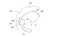
図8は、第1回転体110が停止した状態を示している。第1可動体210及び第1回転体110の相対位置関係に着目した場合、第1可動体210は、第1回転体110に対して初期位置にある。なお、第1回転体110は、電動モータ9の回転に伴って、図8〜図10に示す姿勢だけでなく、回転軸芯C周りに任意の姿勢をとり得る。
FIG. 8 shows a state where the first
この場合、ストッパ224と角度規制部114との間に小さなガタが確保され、第3係止部225とねじりコイルばね50の他端50Bとの間にも小さなガタが確保されている。第1回転体110が第1可動体210に対して正方向に回動しようとすると、第3係止部225がねじりコイルばね50の他端50Bを押して、ねじりコイルばね50をさらに捻ろうとする。この際、ねじりコイルばね50に蓄えられた付勢力により、ねじりコイルばね50の他端50Bは、第3係止部225を第1可動体210に対して逆方向に付勢する。言い換えれば、第1係止部216に係止されたねじりコイルばね50の一端50Aは、第1可動体210を初期位置に向かって正方向に付勢する。この状態では、爪部223は、回転軸芯Cに近づいて、被係合部124から離反している(図8において、爪部223と回転軸芯Cとの距離をR1とする。)。その結果、第1回転体110と第2回転体120との間には、電動モータ9からの回転駆動力を伝達する経路が無くなり、第1回転体110とは無関係に第2回転体120が回転可能な遮断状態となる。なお、第2回転体120は、図8〜図10の紙面手前側に位置しているので、二点鎖線で図示する。
In this case, a small backlash is secured between the
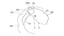
図9及び図10は、電動モータ9に回転駆動されて第1回転体110が図8に示す状態から正方向に回転する状態を示している。第1可動体210及び第1回転体110の相対位置関係に着目した場合、図9は、第1可動体210が第1回転体110に対して初期位置から逆方向に所定角度αまで回動する途中の状態を示し、図10は、第1可動体210が第1回転体110に対して初期位置から逆方向に所定角度αまで回動した状態を示している。
9 and 10 show a state in which the first
上述した通り、制動部材60は、第1可動体210の端面210Bがストッパ224を介して角度規制部114に当て止まるまで、すなわち、第1可動体210が第1回転体110に対して初期位置から逆方向に所定角度αまで回動するまでは、第1可動体210の回転軸芯C周りの回転を抑制する。このため、第1可動体210は、図8に示す状態から図10に示す状態に移行するまでの間、第1回転体110に対して回り遅れる。そして、図10に示すように、端面210Bがストッパ224を介して角度規制部114に当て止まった後は、制動部材60は、電動モータ9から伝達される回転駆動力に負けて、第1可動体210の円柱部211との間に滑りを生じる。その結果、第1可動体210は第1回転体110とともに回転軸芯C周りに正方向に回転する。
As described above, the braking
図9に示す状態(図8に示す状態から図10に示す状態に移行する途中の状態)では、ストッパ224が角度規制部114に当接して正方向に押される一方、制動部材60が第1可動体210の回転軸芯C周りの回転を抑制する。このため、第2可動体220が偏心軸芯H周りに正方向に回動する。この際、ストッパ224は、角度規制部114に接したまま滑ることにより、第2可動体220の姿勢を決める。このため、爪部223は、ストッパ224に案内されて、回転軸芯Cから離れて被係合部124に接近する。
In the state shown in FIG. 9 (the state in the middle of the transition from the state shown in FIG. 8 to the state shown in FIG. 10), the
そして、図10に示す状態まで移行すると、第2可動体220がさらに偏心軸芯H周りに正方向に回動する。このため、爪部223が回転軸芯Cからさらに離れて、被係合部124に係合する(図10において、爪部223と回転軸芯Cとの距離をR2とすると、R1に対してR2が大きくなっている。)。その結果、第1回転体110と第2回転体120との間には、電動モータ9からの回転駆動力を伝達する経路が形成され、第1回転体110と第2回転体120とが正方向に一体回転可能な接続状態となる。そして、第2回転体120は、第1回転体110、第1可動体210及び第2可動体220とともに回転軸芯C周りに正方向に回転する。
Then, when the state moves to the state shown in FIG. 10, the second
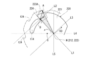
この際、図11に示すように、爪部223が被係合部124に係合した場合において、ストッパ224が角度規制部114に押されることにより、ストッパ224の角度規制部114に対する当接位置Bが力点となり、爪部223の被係合部124に対する係合位置Aが支点となり、偏心ピン222及び偏心軸穴212(偏心軸芯H)が作用点となって、偏心ピン222及び偏心軸穴212が回転軸芯C周りに第1回転体110の回転方向(正方向)と逆方向(点線K1参照)に付勢される。これにより、爪部223と被係合部124とが係合している間、第1可動体210の第1回転体110に対する回り遅れを確実に維持できる。このため、爪部223が回転軸芯Cから距離R2だけ離反する状態が維持され、爪部223と第2回転体120との係合を確実に継続できる。
At this time, as shown in FIG. 11, when the
また、この際、第1可動体210の軸芯H周りの回動に伴って、第3係止部225がねじりコイルばね50の付勢力を蓄えるように、ねじりコイルばね50を正方向にねじる。このため、接続状態では、ねじりコイルばね50に、第1可動体210を初期位置まで復帰させることが可能な強い付勢力が蓄えられる。
At this time, the
次に、電動モータ9の回転が停止して、それまで正方向に回転していた第1回転体110が停止した場合、例えば図10に示す状態で第1回転体110が停止した場合、円柱部211に電動モータ9の回転駆動力が作用しなくなるので、制動部材60が再び第1可動体210の回転軸芯C周りの回転を抑制する。そうすると、図9に示すように、ねじりコイルばね50に蓄えられた強い付勢力が第1回転体110を押し戻すように作用して、第1回転体110を逆方向に回転させる。
Next, when the rotation of the
図9に示す状態(図10に示す状態から図9に示す状態に移行する途中の状態)では、ストッパ224もねじりコイルばね50の他端50Bに押されて角度規制部114に当接したまま逆方向に押し戻される一方、制動部材60が第1可動体210の回転軸芯C周りの回転を抑制する。このため、第2可動体220が偏心軸芯H周りに逆方向に回動する。この際も、ストッパ224は、角度規制部114に接したまま滑ることにより、第2可動体220の姿勢を決める。このため、爪部223は、ストッパ224に案内されて、回転軸芯Cに近づいて被係合部124から離反する。
In the state shown in FIG. 9 (the state in the middle of the transition from the state shown in FIG. 10 to the state shown in FIG. 9), the
そして、図8に示す状態まで移行すると、第2可動体220がさらに偏心軸芯H周りに逆方向に回動し、第1可動体210が第1回転体110に対して初期位置に復帰する。このため、爪部223が回転軸芯Cにさらに近づいて、被係合部124からさらに離反する。その結果、第1回転体110と第2回転体120とが遮断状態となる。要するに、第1回転体110に対する第1可動体210の回転軸芯C周りの円運動が、第2可動体220の偏心回転により、爪部223の往復運動(回転軸芯Cに対して接近(図8のR1参照)又は離反(図10のR2参照)する運動)に変換される。
Then, when the state moves to the state shown in FIG. 8, the second
一方、電動モータ9の誤動作(例えば、電動モータ9の誤配線)により、第1回転体110が図8に示す状態から逆方向に回転する場合、第1可動体210の端面210Aが角度規制部114に当接するので、電動モータ9の回転駆動力が角度規制部114を介して第1可動体210に伝達される。このため、制動部材60は、電動モータ9から伝達される回転駆動力に負けて、円柱部211との間に滑りを生じる。その結果、第1可動体210は第1回転体110とともに回転軸芯C周りに逆方向に回転する。この際、ストッパ224もねじりコイルばね50の他端50Bに押されて角度規制部114に当接したままの状態が維持されるので、第2可動体220は偏心軸芯H周りに回動せず、爪部223が被係合部124から離反したままとなる。その結果、第1回転体110と第2回転体120とは、遮断状態が継続される。
On the other hand, when the first
次に、出力部8について説明する。図1に示すように、出力部8は、大径の第1出力ギヤ8Aと、小径の第2出力ギヤ8Bと、扇型の第3出力ギヤ8Cと、伝達軸8Dとを備える。第1出力ギヤ8A及び第2出力ギヤ8Bは同軸構成の一体品であり、支持軸3と間隔を有して下側ハウジング2A及び上側ハウジング2Bに両端支持された支持軸4に回転可能に支持されている。第1出力ギヤ8Aは、伝達ギヤ129と噛み合っている。第1出力ギヤ8Aの下側に位置する第2出力ギヤ8Bは第3出力ギヤ8Cと噛み合っている。
Next, the
第3出力ギヤ8Cは伝達軸8Dの一端に結合され、伝達軸8Dの中間部は下側ハウジング2Aに回転可能に支持されている。そして、伝達軸8Dの他端は、下側ハウジング2Aの外側に突出しており、作動アーム7と結合されている。
The
すなわち、第2回転体120が回転すれば、伝達ギヤ129、第1出力ギヤ8A、第2出力ギヤ8B、第3出力ギヤ8C及び伝達軸8Dを介して作動アーム7にその回転が伝達されて、作動アーム7が伝達軸8D周りに揺動する。逆に、作動アーム7が伝達軸8Dに揺動すれば、伝達軸8D、第3出力ギヤ8C、第2出力ギヤ8B、第1出力ギヤ8A及び伝達ギヤ129を介して第2回転体120にその揺動が伝達されて、第2回転体120が回転軸芯C周りに回転する。
That is, if the second
上記構成である実施例のクラッチ装置10が適用されたアクチュエータ1は、以下の通り、動作する。
The actuator 1 to which the
コントローラに制御されて電動モータ9が停止した状態では、第1回転体110も停止する。この状態では、上述したように、切替手段20が第1回転体110と第2回転体120とを遮断状態に切り替えるので、第2回転体120は第1回転体110とは無関係に回転可能となる。その結果、作動アーム7は、電動モータ9とは無関係に伝達軸8D周りに揺動可能となる。
In a state where the
その一方、コントローラに制御されて電動モータ9が回転すると、第1回転体110が正方向に回転駆動される。そうすると、上述したように、切替手段20が第1回転体110と第2回転体120とを接続状態に切り替えるので、第2回転体120が第1回転体110とともに正方向に回転する。その結果、作動アーム7にその回転が伝達されて、作動アーム7が伝達軸8D周りに正方向に揺動する。
On the other hand, when the
その後、電動モータ9が停止すれば、切替手段20が再び第1回転体110と第2回転体120とを遮断状態に切り替えるので、作動アーム7は、電動モータ9とは無関係に伝達軸8D周りに揺動可能となる。
After that, if the
なお、作動アーム7を図1に示す状態に復帰させるリターンスプリング(図示せず)を作動アーム7に装着してもよい。この場合、電動モータ9の回転に伴って作動アーム7が図1に示す位置から正方向に揺動した後、電動モータ9の回転が停止すると、リターンスプリングに付勢されて、作動アーム7が電動モータ9とは無関係に、図1に示す位置に早期に復帰できる。
Note that a return spring (not shown) for returning the
また、電動モータ9の誤動作(例えば、電動モータ9の誤配線)により、第1回転体110が逆方向に回転駆動される場合でも、上述したように、切替手段20は、第1回転体110と第2回転体120とを遮断状態に維持する。このため、電動モータ9から作動アーム7に逆方向の回転駆動力が伝達されることはなく、アクチュエータ1の故障を防止できる。
Even when the first
実施例のクラッチ装置10では、第2可動体220が偏心軸芯Hに回動可能に支持される。このため、第1可動体210に対して第2可動体220を回転軸芯Cに沿って差し込むことにより容易に組み付けでき、組み付け作業の簡素化を実現できる。また、第1可動体210及び第2可動体220の形状も簡素化できる。例えば、上記従来技術のように、第1可動体210に対して、回転軸芯Cと直交する平面に沿って、回転軸芯Cの径方向と交差する方向に延びる段付孔を貫設する必要がなくなる。このため、射出成形金型等の製造設備もスライドコア等の複雑な機構が不要となり、簡素化できる。
In the
したがって、このクラッチ装置10及びアクチュエータ1は、製造コストの低廉化を実現できる。
Therefore, the
また、このクラッチ装置10は、簡素な構成である角度規制部114、偏心軸穴212、偏心ピン22、爪部223及びストッパ224等を採用することで、第1回転体110に対する第1可動体210の回転軸芯C周りの円運動を、第2可動体220の偏心回転により、爪部223の往復運動(回転軸芯Cに対して接近又は離反する運動)に変換することを容易に実現でき、その結果、製造コストの低廉化を確実に実現できる。
In addition, the
特に、このクラッチ装置10では、図10に示すように、第1可動体210が初期位置から所定角度αまで回動することにより、回転軸芯Cと偏心軸芯Hと爪部223とがこの順序で略直線状に並んだ状態で、爪部223が被係合部124と係合する。この場合、爪部223を可能な限り突出させた状態で接続状態とすることができるので、このクラッチ装置10は、爪部223の進退ストロークを確保し易い。その結果、第1回転体110の初期位置から所定角度αまでの可動範囲を小さくでき、また、第2可動体220を小型化し易い。
In particular, in the
また、仮に、角度規制部114、爪部223及びストッパ224の相対位置関係を変更して、当接位置B、係合位置A、回転軸芯C及び偏心軸芯Hのレイアウトを図12のように変更した比較例を想定する。図12の比較例では、爪部223が被係合部124に係合した場合において、ストッパ224が角度規制部114に押されることにより、当接位置Bが力点となり、係合位置Aが支点となり、偏心ピン222及び偏心軸穴212(偏心軸芯H)が作用点となって、偏心ピン222及び偏心軸穴212が回転軸芯C周りに第1回転体110の回転方向(正方向)と同じ方向(点線K2参照)に付勢される。そうすると、係合中は回り遅れを維持しているべき第1可動体210が第1回転体110に対して先行回転し易くなる。そして、この先行回転が生じて第1可動体210の回り遅れを維持できなくなった場合には、爪部223が回転軸芯Cに接近して、爪部223と被係合部124との係合を継続できなくなる。
Further, if the relative positional relationship of the
この点、このクラッチ装置10では、図11を示して上述した通り、爪部223が被係合部124に係合すると、偏心ピン222及び偏心軸穴212(偏心軸芯H)が回転軸芯C周りに第1回転体110の回転方向(正方向)と逆方向(点線K1参照)に付勢されるので、爪部223と被係合部124とが係合している間、第1可動体210の第1回転体110に対する回り遅れを確実に維持できる。このため、このロック装置10は、「第1可動体210が第1回転体110に対して先行回転して爪部223と第2回転体120との係合を継続できなくなる現象」を回避できる。
In this regard, in this
ここで、「第1可動体210が第1回転体110に対して先行回転して爪部223と第2回転体120との係合を継続できなくなる現象」を確実に回避できる条件を以下に説明する。これらの条件は、発明者らが当接位置B、係合位置A、回転軸芯C及び偏心軸芯Hのレイアウトを様々な態様に変更して機構学的に考察し、さらに、製品設計上の実用性を考慮して定めたものである。
Here, the conditions for reliably avoiding the phenomenon that “the first
爪部223が第2回転体120に係合した場合を示す図11及び図12において、当接位置Bと偏心軸芯Hとを結んだ直線をL1とし、直線L1に直交し、当接位置Bを通過する直線をL2とし、直線L1に直交し、偏心軸芯Hを通過する直線をL3とし、偏心軸芯Hと回転軸芯Cとを結んだ直線をL4とし、直線L4に直交し、偏心軸芯Hを通過する直線をL5とする。
11 and 12 showing the case where the
そうすると、実施例のロック装置10では、図11に示すように、回転軸芯Cは、直線L2と直線L3とに挟まれる領域に存在し、爪部223は、直線L4により仕切られる2つの領域のうち、偏心軸芯Hを基準として第1回転体の回転方向(正方向)と逆方向にある領域(図11においてL4より上側の領域)に存在し、当接位置Bは、直線L5により仕切られる2つの領域のうち、回転軸芯Cがある領域(図11においてL5より左側の領域)に存在している。このような条件を満たすことにより、爪部223が被係合部124に係合すると、偏心ピン222及び偏心軸穴212(偏心軸芯H)が回転軸芯C周りに第1回転体110の回転方向(正方向)と逆方向に付勢される構成を確実に実現でき、「第1可動体が第1回転体に対して先行回転して爪部と第2回転体との係合を継続できなくなる現象」を確実に回避できる。
Then, in the
これに対して、図12の比較例では、回転軸芯Cは、直線L2と直線L3とに挟まれる領域に存在しておらず、当接位置Bは、直線L5により仕切られる2つの領域のうち、回転軸芯Cがある領域(図12においてL5より左側の領域)に存在していない。このように上記各条件を満たさない比較例では、上述した通り、「第1可動体が第1回転体に対して先行回転して爪部と第2回転体との係合を継続できなくなる現象」が生じ易い。 On the other hand, in the comparative example of FIG. 12, the rotation axis C does not exist in the region sandwiched between the straight line L2 and the straight line L3, and the contact position B is the two regions partitioned by the straight line L5. Of these, the rotation axis C is not present in a region (a region on the left side of L5 in FIG. 12). As described above, in the comparative example that does not satisfy the above conditions as described above, “the first movable body rotates in advance with respect to the first rotating body and the engagement between the claw portion and the second rotating body cannot be continued. "Is likely to occur.
さらに、このクラッチ装置10は、上記具体的構成により、第1回転体110、第1可動体210、第2可動体220及び第2回転体120を回転軸芯Cに沿って順番に組み付られる。その途中で、ねじりコイルばね50を第1可動体210に保持させることができる。その結果、組み付け作業を大幅に簡素化でき、製造コストの低廉化をより確実に実現できる。
Further, in the
また、このクラッチ装置10は、支持軸3及び軸穴214により、強固に第1可動体210を回転軸芯C周りに回動可能に支持できる。また、上記構成である平板部221により、第2可動体220を大型化することなく、第2可動体220の強度を高くできる。その結果、このクラッチ装置及びアクチュエータ1は、耐久性が向上する。
Further, the
(変形例)
変形例のクラッチ装置は、実施例の第2可動体220における爪部223の代わりに、図13〜図15に示すように、ストッパ224の近傍に配設された爪部223Aを採用している。変形例のクラッチ装置における爪部223A以外の構成は、全て実施例のクラッチ装置10と同一である。このため、同一構成については同一の符号を付して説明を省略又は簡略する。
(Modification)
The clutch device of the modified example employs a
図13及び図14に示すように、爪部223Aは、平板部221の外周縁側から径外方向に突出する略三角突起である。爪部223Aは、偏心軸芯Hに対してストッパ224と略同一方向に位置し、ストッパ224よりも偏心軸芯Hから離れるように突出している。
As shown in FIGS. 13 and 14, the
図14は、図8に示すクラッチ装置10と同じ状態、すなわち、第1回転体110が停止した状態を示している。この状態では、爪部223Aは、回転軸芯Cに近づいて、被係合部124から離反している(図14において、爪部223Aと回転軸芯Cとの距離をR1とする。)。その結果、第1回転体110と第2回転体120とが遮断状態となる。
FIG. 14 shows the same state as the
図15は、図10に示すクラッチ装置10と同じ状態、すなわち、電動モータ9に回転駆動されて第1回転体110が正方向に回転することにより、第1可動体210が第1回転体110に対して初期位置から逆方向に所定角度αまで回動した状態を示している。図14の状態から図15の状態まで移行すると、第2可動体220が偏心軸芯H周りに正方向に回動する。このため、爪部223Aが回転軸芯Cから離れて、被係合部124に係合する(図15において、爪部223Aと回転軸芯Cとの距離をR2とすると、R1に対してR2が大きくなっている。)。その結果、第1回転体110と第2回転体120とが接続状態となる。
FIG. 15 shows the same state as the
この際、図16に示すように、爪部223Aが被係合部124に係合した場合において、ストッパ224が角度規制部114に押されることにより、ストッパ224の角度規制部114に対する当接位置Bが力点となり、爪部223Aの被係合部124に対する係合位置Aが支点となり、偏心ピン222及び偏心軸穴212(偏心軸芯H)が作用点となって、偏心ピン222及び偏心軸穴212が回転軸芯C周りに第1回転体110の回転方向(正方向)と逆方向(点線K3参照)に付勢される。これにより、爪部223Aと被係合部124とが係合している間、第1可動体210の第1回転体110に対する回り遅れを確実に維持できる。このため、爪部223Aが回転軸芯Cから距離R2だけ離反する状態が維持され、爪部223Aと第2回転体120との係合を確実に継続できる。
At this time, as shown in FIG. 16, when the
上記構成である変形例のロック装置も、実施例のクラッチ装置10と同様の作用効果を奏することができる。
The lock device of the modified example having the above-described configuration can also achieve the same operational effects as the
特に、このクラッチ装置では、図14に示すように、第1可動体210が初期位置に位置することにより、偏心軸芯Hと回転軸芯Cと爪部223Aとがこの順序で略直線状に並んだ状態で、爪部223Aが被係合部124と離反する。この場合、爪部223Aを可能な限り引っ込めた状態で遮断状態とすることができるので、このクラッチ装置は、爪部223Aの進退ストロークを確保し易い。その結果、第1回転体110の初期位置から所定角度αまでの可動範囲を小さくでき、また、第2可動体220を小型化し易い。
In particular, in this clutch device, as shown in FIG. 14, when the first
また、このロック装置では、実施例のロック装置10と同様、爪部223Aが第2回転体120に係合した場合を示す図16において、回転軸芯Cは、直線L2と直線L3とに挟まれる領域に存在し、爪部223Aは、直線L4により仕切られる2つの領域のうち、偏心軸芯Hを基準として第1回転体の回転方向(正方向)と逆方向にある領域(図16においてL4より上側の領域)に存在し、当接位置Bは、直線L5により仕切られる2つの領域のうち、回転軸芯Cがある領域(図16においてL5より左側の領域)に存在している。このような条件を満たすことにより、爪部223Aが被係合部124に係合すると、偏心ピン222及び偏心軸穴212(偏心軸芯H)が回転軸芯C周りに第1回転体110の回転方向(正方向)と逆方向(点線K3参照)に付勢される構成を確実に実現でき、「第1可動体が第1回転体に対して先行回転して爪部と第2回転体との係合を継続できなくなる現象」をより確実に回避できる。
Further, in this locking device, similarly to the
以上において、本発明を実施例に即して説明したが、本発明は上記実施例に制限されるものではなく、その趣旨を逸脱しない範囲で適宜変更して適用できることはいうまでもない。 While the present invention has been described with reference to the embodiments, it is needless to say that the present invention is not limited to the above-described embodiments and can be appropriately modified and applied without departing from the spirit thereof.
例えば、第1可動体の偏心部が円柱軸体であり、第2可動体の被偏心部が円柱軸体を回転可能に支持する軸穴であってもよい。 For example, the eccentric part of the first movable body may be a cylindrical shaft body, and the eccentric part of the second movable body may be a shaft hole that rotatably supports the cylindrical shaft body.
また、第2可動体における被偏心部、爪部及びストッパは、本発明の作用効果を奏することができれば、どのような相対位置関係でもかまわない。 Further, the eccentric portion, the claw portion, and the stopper in the second movable body may have any relative positional relationship as long as the effects of the present invention can be achieved.
本発明は開閉体のロック装置等に利用可能である。 The present invention can be used for an opening / closing body locking device or the like.
2A、2B…ベース部材(2A…下側ハウジング、2B…上側ハウジング)
C…回転軸芯
9…駆動源(電動モータ)
110…第1回転体
120…第2回転体
20…切替手段
10…クラッチ装置
α…所定角度
210…第1可動体
H…偏心軸芯
220…第2可動体
50…付勢部材(ねじりコイルばね)
60…制動部材
114…角度規制部
212…偏心部(偏心軸穴)
222…被偏心部(偏心ピン)
223、223A…爪部
224…ストッパ
A…爪部の第2回転体に対する係合位置
B…ストッパの角度規制部に対する当接位置
L1…ストッパの角度規制部に対する当接位置と、偏心軸芯とを結んだ直線
L2…直線L1に直交し、当接位置を通過する直線
L3…直線L1に直交し、偏心軸芯を通過する直線
L4…偏心軸芯と回転軸芯とを結んだ直線
L5…直線L4に直交し、偏心軸芯を通過する直線
113…回転軸穴
111…第1円盤部
112…第1円筒部
119…外歯
121…第2円盤部
122…第2円筒部
124…被係合部
100…内部空間
211…円柱部
216…第1係止部
217…第2係止部
225…第3係止部
50A…ねじりコイルばねの一端
50B…ねじりコイルばねの他端
3…支持軸
213…凸部
214…軸穴
226…スリット
221…平板部
8…出力部
1…アクチュエータ
2A, 2B ... Base member (2A ... Lower housing, 2B ... Upper housing)
C ... Rotating
DESCRIPTION OF
60 ...
222 ... eccentric part (eccentric pin)
223, 223A ... claw
Claims (8)
前記ベース部材に対して回転軸芯周りに回転可能に支持され、駆動源に回転駆動される第1回転体と、
前記ベース部材に対して前記回転軸芯周りに回転可能に支持され、前記第1回転体に隣接する第2回転体と、
前記第1回転体と前記第2回転体との間に設けられ、前記第1回転体と前記第2回転体とが一体回転する接続状態と、前記第1回転体とは無関係に前記第2回転体が回転可能な遮断状態とを切り替える切替手段とを備えるクラッチ装置であって、
前記切替手段は、前記第1回転体に対して回動角度が初期位置から所定角度までの間に制限されつつ前記回転軸芯周りに回動可能に支持された第1可動体と、
前記第1可動体に対して前記回転軸芯から偏心した偏心軸芯周りに回動可能に支持され、前記第1回転体が前記駆動源に回転駆動されない場合、前記第1可動体が前記初期位置に位置することにより前記回転軸芯に近づいて前記第2回転体から離反する一方、前記第1回転体が前記駆動源に回転駆動されて正方向に回転する場合、前記第1可動体が前記初期位置から回動することにより前記回転軸芯から離れて前記第2回転体に係合する第2可動体と、
前記第1回転体又は前記第2可動体と前記第1可動体との間に設けられ、前記第1可動体を前記初期位置に向かって付勢する付勢部材と、
前記ベース部材に設けられ、前記第1可動体に所定の摩擦力を付与して、前記第1可動体の前記回転軸芯周りの回転を制動し、前記第1回転体に対する前記第1可動体の回り遅れを生じさせる制動部材とを有することを特徴とするクラッチ装置。 A base member;
A first rotating body that is rotatably supported around the rotation axis with respect to the base member, and is driven to rotate by a drive source;
A second rotating body that is rotatably supported around the rotation axis with respect to the base member, and is adjacent to the first rotating body;
The second rotating body is provided between the first rotating body and the second rotating body, and the second rotating body is independent of the first rotating body and the connection state in which the first rotating body and the second rotating body rotate integrally. A clutch device comprising switching means for switching between a shut-off state in which the rotating body can rotate,
The switching means includes a first movable body supported so as to be rotatable around the rotation axis while the rotation angle is limited between an initial position and a predetermined angle with respect to the first rotation body;
When the first movable body is rotatably supported around an eccentric axis that is eccentric from the rotation axis, and the first movable body is not driven to rotate by the drive source, the first movable body is When the first rotating body is driven to rotate by the drive source and rotates in the positive direction while approaching the rotating shaft core and moving away from the second rotating body by being positioned, the first movable body is A second movable body engaged with the second rotating body away from the rotation axis by rotating from the initial position;
A biasing member that is provided between the first rotating body or the second movable body and the first movable body, and biases the first movable body toward the initial position;
The first movable body is provided on the base member, applies a predetermined frictional force to the first movable body, brakes the rotation of the first movable body around the rotation axis, and the first movable body with respect to the first rotary body. And a braking member that causes a delay in rotation.
前記第1可動体には、前記偏心軸芯を形成する偏心部が形成され、
前記第2可動体には、前記偏心部と係合する被偏心部と、前記付勢部材によって前記角度規制部と当接するストッパと、前記偏心軸芯及び前記ストッパから離れて設けられ、前記第1回転体が正方向に回転することにより前記角度規制部と摺接する前記ストッパに案内された状態で前記回転軸芯から離れ、前記第2回転体と係合を継続可能な爪部とが形成されている請求項1又は2記載のクラッチ装置。 The first rotating body is formed with an angle restricting portion that restricts a rotation angle of the first movable body,
The first movable body is formed with an eccentric portion that forms the eccentric shaft core,
The second movable body is provided with an eccentric portion that engages with the eccentric portion, a stopper that comes into contact with the angle restricting portion by the biasing member, a distance from the eccentric shaft core and the stopper, A claw portion that is separated from the rotation axis while being guided by the stopper that is in sliding contact with the angle restricting portion when the one rotating body rotates in a forward direction and that can continue to engage with the second rotating body is formed. The clutch device according to claim 1 or 2, wherein
前記ストッパが前記角度規制部に押されることにより、前記爪部の前記第2回転体に対する係合位置を支点として、前記被偏心部及び前記偏心部が前記回転軸芯周りに前記第1回転体の回転方向と逆方向に付勢されるように構成されている請求項3記載のクラッチ装置。 When the claw portion is engaged with the second rotating body,
When the stopper is pushed by the angle restricting portion, the eccentric portion and the eccentric portion are arranged around the rotation axis with the engaging position of the claw portion with respect to the second rotating body as a fulcrum. The clutch device according to claim 3, wherein the clutch device is configured to be urged in a direction opposite to a rotation direction of the motor.
前記ストッパの前記角度規制部に対する当接位置と、前記偏心軸芯とを結んだ直線をL1とし、前記直線L1に直交し、前記当接位置を通過する直線をL2とし、前記直線L1に直交し、前記偏心軸芯を通過する直線をL3とし、前記偏心軸芯と前記回転軸芯とを結んだ直線をL4とし、前記直線L4に直交し、前記偏心軸芯を通過する直線をL5とすると、
前記回転軸芯は、前記直線L2と前記直線L3とに挟まれる領域に存在し、
前記爪部は、前記直線L4により仕切られる2つの領域のうち、前記偏心軸芯を基準として前記第1回転体の回転方向と逆方向にある領域に存在し、
前記当接位置は、前記直線L5により仕切られる2つの領域のうち、前記回転軸芯がある領域に存在している請求項4記載のクラッチ装置。 When the claw portion is engaged with the second rotating body,
A straight line connecting the contact position of the stopper with the angle restricting portion and the eccentric shaft core is L1, orthogonal to the straight line L1, and a straight line passing through the contact position is L2, and orthogonal to the straight line L1. A straight line passing through the eccentric shaft core is L3, a straight line connecting the eccentric shaft core and the rotary shaft core is L4, a straight line orthogonal to the straight line L4 and passing through the eccentric shaft core is L5. Then
The rotation axis is present in a region sandwiched between the straight line L2 and the straight line L3,
The claw portion is present in a region in a direction opposite to the rotation direction of the first rotating body, with respect to the eccentric shaft core, out of two regions partitioned by the straight line L4.
The clutch device according to claim 4, wherein the contact position is present in a region where the rotation axis is located, of two regions partitioned by the straight line L5.
前記第2回転体は、前記第1円盤部と間隔を有して対向する第2円盤部と、前記第2円盤部の外周縁に形成され、前記回転軸芯と同軸に前記第1円筒部に向かって延在する第2円筒部と、前記第2円筒部の内周面に形成され、前記爪部と係合する被係合部とを有し、
前記第1円盤部、前記第1円筒部、前記第2円盤部及び前記第2円筒部により内部空間が区画され、
前記内部空間内には、前記第1円盤部に隣接する前記第1可動体と、前記第1可動体と前記第2円盤部とに挟まれる前記第2可動体と、前記第1可動体に保持される前記付勢部材としてのねじりコイルばねとが収容され、
前記第1円盤部は前記内部空間に向かって前記角度規制部を突出させており、
前記第1可動体には、一面側に延びて前記回転軸穴から突出し、前記制動部材と摺接する円柱部と、他面側に凹設された前記偏心部としての偏心軸穴と、他面側に形成され、前記ねじりコイルばねの一端を係止する第1係止部と、他面側に形成され、前記ねじりコイルばねの他端を係止する第2係止部とが形成され、
前記第2可動体には、前記偏心軸穴に挿入される前記被偏心部としての偏心ピンと、組付時に前記角度規制部と前記第2係止部との間に突出し、前記偏心軸芯周りに回動することにより前記ねじりコイルばねの他端を係止する第3係止部とが形成されている請求項3乃至5のいずれか1項記載のクラッチ装置。 The first rotating body is formed at a first disk portion having a rotation shaft hole coaxial with the rotation shaft core, and at an outer peripheral edge of the first disk portion, and extends first coaxially with the rotation shaft core. 1 cylindrical portion and external teeth formed on the outer peripheral surface of the first cylindrical portion,
The second rotating body is formed at a second disk portion facing the first disk portion with an interval, and an outer peripheral edge of the second disk portion, and is coaxial with the rotating shaft and the first cylindrical portion. A second cylindrical portion extending toward the inner surface, and an engaged portion that is formed on the inner peripheral surface of the second cylindrical portion and engages with the claw portion,
An internal space is partitioned by the first disk part, the first cylindrical part, the second disk part, and the second cylindrical part,
In the internal space, the first movable body adjacent to the first disk portion, the second movable body sandwiched between the first movable body and the second disk portion, and the first movable body A torsion coil spring as the biasing member to be held is accommodated,
The first disk part projects the angle restricting part toward the internal space,
The first movable body includes a cylindrical portion that extends to one surface and protrudes from the rotation shaft hole and is in sliding contact with the braking member, an eccentric shaft hole as the eccentric portion that is recessed on the other surface side, and another surface. A first locking portion that locks one end of the torsion coil spring and a second locking portion that locks the other end of the torsion coil spring formed on the other surface side,
The second movable body includes an eccentric pin as the eccentric portion inserted into the eccentric shaft hole, and protrudes between the angle restricting portion and the second locking portion when assembled, and around the eccentric shaft core. The clutch device according to any one of claims 3 to 5, wherein a third locking portion that locks the other end of the torsion coil spring by rotating in the direction is formed.
前記第1可動体には、前記円柱部の他面側に突出し、前記回転軸芯と同軸の凸部と、前記円柱部から前記凸部まで前記支持軸を挿通させる軸穴とが形成され、
前記第2可動体には、前記回転軸芯に直交する平面に沿う平板形状とされ、前記偏心軸芯周りの回動時に前記支持軸及び前記凸部との干渉を回避するスリットが自己の中央に貫設された平板部が形成されている請求項6記載のクラッチ装置。 A support shaft that forms the rotating shaft core is fixed to the base member,
The first movable body is formed with a convex portion that protrudes to the other surface side of the cylindrical portion, is coaxial with the rotational axis, and a shaft hole that allows the support shaft to be inserted from the cylindrical portion to the convex portion.
The second movable body has a flat plate shape along a plane orthogonal to the rotation axis, and a slit that avoids interference with the support shaft and the convex portion when rotating around the eccentric axis is in the center of the second movable body. The clutch device according to claim 6, wherein a flat plate portion penetrating the shaft is formed.
請求項1乃至7のいずれか1項記載のクラッチ装置と、
前記第2回転体の回転に伴って動作する出力部とを備えることを特徴とするアクチュエータ。 The drive source fixed to the base member;
The clutch device according to any one of claims 1 to 7,
An actuator comprising: an output unit that operates in accordance with the rotation of the second rotating body.
Priority Applications (1)
| Application Number | Priority Date | Filing Date | Title |
|---|---|---|---|
| JP2010125567A JP5460468B2 (en) | 2010-06-01 | 2010-06-01 | Clutch device and actuator |
Applications Claiming Priority (1)
| Application Number | Priority Date | Filing Date | Title |
|---|---|---|---|
| JP2010125567A JP5460468B2 (en) | 2010-06-01 | 2010-06-01 | Clutch device and actuator |
Publications (2)
| Publication Number | Publication Date |
|---|---|
| JP2011252524A JP2011252524A (en) | 2011-12-15 |
| JP5460468B2 true JP5460468B2 (en) | 2014-04-02 |
Family
ID=45416613
Family Applications (1)
| Application Number | Title | Priority Date | Filing Date |
|---|---|---|---|
| JP2010125567A Active JP5460468B2 (en) | 2010-06-01 | 2010-06-01 | Clutch device and actuator |
Country Status (1)
| Country | Link |
|---|---|
| JP (1) | JP5460468B2 (en) |
Families Citing this family (1)
| Publication number | Priority date | Publication date | Assignee | Title |
|---|---|---|---|---|
| JP6520350B2 (en) * | 2015-04-23 | 2019-05-29 | 株式会社アンセイ | Clutch device and actuator |
Family Cites Families (2)
| Publication number | Priority date | Publication date | Assignee | Title |
|---|---|---|---|---|
| JP4659559B2 (en) * | 2005-08-23 | 2011-03-30 | 三井金属アクト株式会社 | Electric actuator |
| JP2010090913A (en) * | 2008-10-03 | 2010-04-22 | Mitsuba Corp | Clutch mechanism and door lock drive assembly |
-
2010
- 2010-06-01 JP JP2010125567A patent/JP5460468B2/en active Active
Also Published As
| Publication number | Publication date |
|---|---|
| JP2011252524A (en) | 2011-12-15 |
Similar Documents
| Publication | Publication Date | Title |
|---|---|---|
| KR102097056B1 (en) | Motor vehicle door lock | |
| US10563434B2 (en) | Locking unit for a motor vehicle | |
| US8757679B2 (en) | Closing device comprising two pawls and a motor-driven actuating mechanism | |
| JP5469789B2 (en) | A lock unit having a plurality of claw portions and a claw portion having a spring | |
| JP4532555B2 (en) | Steering spindle lock device for automobile | |
| RU2652580C2 (en) | Lock for a motor vehicle door | |
| JP5260360B2 (en) | Electric steering lock device | |
| US7263909B2 (en) | Drive device | |
| JP4448512B2 (en) | Device for locking the steering shaft of an automobile | |
| US9079517B2 (en) | Dual cam recliner | |
| US20110265586A1 (en) | Glove box actuator | |
| JP5260358B2 (en) | Electric steering lock device | |
| KR101589331B1 (en) | Drive unit comprising a blocked functional element for a central locking mechanism | |
| EP0684356B1 (en) | Door lock driving device | |
| JP7121055B2 (en) | vehicle door handle assembly | |
| JP5460468B2 (en) | Clutch device and actuator | |
| JP5450265B2 (en) | Clutch device and actuator | |
| JP3761041B2 (en) | Electric actuator | |
| JP2018200773A (en) | Switch mechanism and geared motor, and damper device | |
| US20200166131A1 (en) | Parking lock and a transmission having the parking lock | |
| US9827949B2 (en) | Electric steering lock device | |
| CN113904498B (en) | Rotary actuator | |
| CN111379480B (en) | Door latch lock device | |
| US20210102412A1 (en) | Vehicle door lock device | |
| JP6337826B2 (en) | Clutch device and actuator |
Legal Events
| Date | Code | Title | Description |
|---|---|---|---|
| A621 | Written request for application examination |
Free format text: JAPANESE INTERMEDIATE CODE: A621 Effective date: 20130501 |
|
| A977 | Report on retrieval |
Free format text: JAPANESE INTERMEDIATE CODE: A971007 Effective date: 20131218 |
|
| TRDD | Decision of grant or rejection written | ||
| A01 | Written decision to grant a patent or to grant a registration (utility model) |
Free format text: JAPANESE INTERMEDIATE CODE: A01 Effective date: 20140107 |
|
| A61 | First payment of annual fees (during grant procedure) |
Free format text: JAPANESE INTERMEDIATE CODE: A61 Effective date: 20140114 |
|
| R150 | Certificate of patent or registration of utility model |
Ref document number: 5460468 Country of ref document: JP Free format text: JAPANESE INTERMEDIATE CODE: R150 Free format text: JAPANESE INTERMEDIATE CODE: R150 |
|
| R250 | Receipt of annual fees |
Free format text: JAPANESE INTERMEDIATE CODE: R250 |
|
| R250 | Receipt of annual fees |
Free format text: JAPANESE INTERMEDIATE CODE: R250 |
|
| R250 | Receipt of annual fees |
Free format text: JAPANESE INTERMEDIATE CODE: R250 |
|
| R250 | Receipt of annual fees |
Free format text: JAPANESE INTERMEDIATE CODE: R250 |
|
| R250 | Receipt of annual fees |
Free format text: JAPANESE INTERMEDIATE CODE: R250 |
|
| R250 | Receipt of annual fees |
Free format text: JAPANESE INTERMEDIATE CODE: R250 |
|
| R250 | Receipt of annual fees |
Free format text: JAPANESE INTERMEDIATE CODE: R250 |
|
| R250 | Receipt of annual fees |
Free format text: JAPANESE INTERMEDIATE CODE: R250 |