JP4932202B2 - Part program generating apparatus for image measuring apparatus, part program generating method for image measuring apparatus, and part program generating program for image measuring apparatus - Google Patents
Part program generating apparatus for image measuring apparatus, part program generating method for image measuring apparatus, and part program generating program for image measuring apparatus Download PDFInfo
- Publication number
- JP4932202B2 JP4932202B2 JP2005262338A JP2005262338A JP4932202B2 JP 4932202 B2 JP4932202 B2 JP 4932202B2 JP 2005262338 A JP2005262338 A JP 2005262338A JP 2005262338 A JP2005262338 A JP 2005262338A JP 4932202 B2 JP4932202 B2 JP 4932202B2
- Authority
- JP
- Japan
- Prior art keywords
- image
- feature
- measurement
- part program
- work
- Prior art date
- Legal status (The legal status is an assumption and is not a legal conclusion. Google has not performed a legal analysis and makes no representation as to the accuracy of the status listed.)
- Active
Links
Images


Description
本発明は、測定対象(以下、ワーク)に対する測定手順を記述したパートプログラムを生成するための画像測定装置用パートプログラム生成装置、その方法、及びプログラムに関する。 The present invention relates to a part program generation device for an image measurement device, a method thereof, and a program for generating a part program that describes a measurement procedure for a measurement object (hereinafter, a workpiece).
従来、CNC(Computer Numerical Control)タイプの画像測定装置において、ワークの測定条件を記述したパートプログラムは、おおむね次の2つの方法を用いて作成される。一つは、測定機上に実際ワークを載置して、測定手順を画像測定装置に記憶させる方法(オンラインティーチング)であり、もう一つはワークの2次元CADデータを画面上に表示させ、マウス操作等により特定領域を指定し、測定手順を画像測定装置に記憶させる方法(オフラインティーチング)である。この他、ワークの画像を複数範囲に分割して撮影した後、複数の画像を一枚に合成するとともに、各複数範囲の画像の位置関係を記録させ、その一枚に合成したワークの画像に基づき、パートプログラムを作成する技術が開示されている(特許文献1)。 2. Description of the Related Art Conventionally, in a CNC (Computer Numerical Control) type image measuring apparatus, a part program that describes workpiece measurement conditions is generally created using the following two methods. One is a method (online teaching) in which an actual work is placed on a measuring machine and the measurement procedure is stored in the image measuring device. The other is to display the two-dimensional CAD data of the work on the screen. This is a method (offline teaching) in which a specific region is designated by operating a mouse or the like, and the measurement procedure is stored in the image measuring apparatus. In addition, after the work image is divided into a plurality of ranges and photographed, the plurality of images are combined into one sheet, and the positional relationship between the images of each of the plurality of ranges is recorded, and the combined work image is combined into one sheet. Based on this, a technique for creating a part program is disclosed (Patent Document 1).
上記のティーチングにおいて、例えば、一定形状のエッジが等方向及び等間隔に形成されたワークを対象とする場合、等間隔でエッジを測定する、所謂、STEP&REPEAT機能を組み込めば、迅速にパートプログラムを作成することが可能となる。
しかしながら、実際、多くのワークは、一定形状のエッジを複数有しているものの、全てのそれら一定形状のエッジが等方向及び等間隔に配置されているとは限らない。したがって、STEP&REPEAT機能をワーク全体に適応可能であるケースは稀であり、多くの場合、オペレータは、ワークに対して部分的にSTEP&REPEAT機能を使うか、或いは、マニュアルにより一定形状のエッジをそれぞれ個別に指定する必要があり、パートプログラムの生成には、未だ多くの時間を要している。 However, in fact, many workpieces have a plurality of fixed-shaped edges, but not all of the fixed-shaped edges are arranged in equal directions and at equal intervals. Therefore, it is rare that the STEP & REPEAT function can be applied to the entire work. In many cases, the operator uses the STEP & REPEAT function partially for the work, or each edge of a fixed shape is manually specified. It must be specified, and it still takes a lot of time to generate the part program.
本発明は、このような問題に鑑みてなされたものであって、ワークが一定形状のエッジを複数有する場合、マニュアル操作によって、それぞれ個別にエッジを指定することなく、迅速にパートプログラムを作成する画像測定装置用パートプログラム生成装置、その方法、及びそのプログラムを提供することを目的とする。 The present invention has been made in view of such problems, and when a workpiece has a plurality of edges having a fixed shape, a part program can be quickly created without manually specifying each edge manually. An object of the present invention is to provide a part program generation device for an image measurement device, a method thereof, and a program thereof.
上記の目的の達成のため、本出願の第1の発明に係る画像測定装置用パートプログラム生成装置は、ワークを撮像して得られる画像データに基づいてワークを測定する画像測定装置に用いられ、測定の手順を記述したパートプログラムを生成するパートプログラム生成装置であって、前記ワークに対して領域を指定する領域指定手段と、前記領域を複数の分割領域に分割する領域分割手段と、それぞれの分割領域に移動して前記分割領域の位置情報を取得すると共に、それぞれの分割領域内の前記ワークを撮像して複数の第1ワーク画像を取得する撮像手段と、前記位置情報をもとに複数の前記第1ワーク画像を接合することにより、第2ワーク画像を取得する画像接合手段と、前記第2ワーク画像を表示する表示手段と、前記第2ワーク画像から特定の特徴を有する特徴画像を抽出する特徴画像抽出手段と、指定された前記特徴画像の少なくとも一つに測定条件を指定する測定条件指定手段と、指定された前記測定条件を全ての前記特徴画像に割り当てる測定条件割当手段とを備えたことを特徴とする。また、前記測定箇所抽出手段は、前記第2ワーク画像の画素数及び輝度に基づき前記特徴画像を抽出することが望ましい。さらに、前記測定対象抽出手段は、前記特徴画像の位置、及び図形角度を検出し、前記測定条件割当手段は、前記特徴画像の位置及び図形角度に基づき前記測定条件を割り当てることが望ましい。 In order to achieve the above object, the part program generation device for an image measurement device according to the first invention of the present application is used in an image measurement device that measures a workpiece based on image data obtained by imaging the workpiece, A part program generation device for generating a part program describing a measurement procedure, an area designating unit for designating an area for the work, an area dividing unit for dividing the area into a plurality of divided areas, An image pickup unit that moves to a divided area to acquire position information of the divided area, images the workpiece in each divided area and acquires a plurality of first work images, and a plurality of pieces based on the position information by joining the first workpiece image, and the image joining means for acquiring second workpiece image, and display means for displaying the second workpiece image, said second workpiece image All of the features and the feature image extracting means for extracting feature image having a particular characteristic, the measurement condition specifying means for specifying at least one the measurement conditions specified the feature image, the designated said measurement condition from It is characterized by comprising measurement condition assigning means for assigning to an image. Moreover, it is preferable that the measurement location extraction unit extracts the feature image based on the number of pixels and the luminance of the second work image . Furthermore, it is preferable that the measurement object extraction unit detects the position and graphic angle of the feature image, and the measurement condition assigning unit allocates the measurement condition based on the position and graphic angle of the feature image .
上記の目的の達成のため、本出願の第2の発明に係る画像測定装置用パートプログラム生成方法は、ワークを撮像して得られる画像データに基づいてワークを測定する画像測定装置に用いられ、測定の手順を記述したパートプログラムを生成するパートプログラム生成方法であって、前記ワークに対して領域を指定するステップと、前記領域を複数の分割領域に分割するステップと、それぞれの分割領域に移動して前記分割領域の位置情報を取得すると共に、それぞれの分割領域内の前記ワークを撮像して複数の第1ワーク画像を取得するステップと、前記位置情報をもとに複数の前記第1ワーク画像を接合することにより、第2ワーク画像を取得するステップと、前記第2ワーク画像を表示するステップと、前記第2ワーク画像から特定の特徴を有する特徴画像を抽出するステップと、指定された前記特徴画像の少なくとも一つに測定条件を指定するステップと、指定された前記測定条件を全ての前記特徴画像に割り当てるステップとを有することを特徴とする。 In order to achieve the above object, the image measurement device part program generation method according to the second invention of the present application is used in an image measurement device that measures a workpiece based on image data obtained by imaging the workpiece, A part program generation method for generating a part program that describes a measurement procedure, the step of specifying an area for the workpiece, the step of dividing the area into a plurality of divided areas, and moving to each divided area And acquiring the position information of the divided areas, capturing a plurality of first work images by imaging the work in each divided area, and a plurality of the first works based on the position information by joining the images, obtaining a second workpiece image, and displaying the second workpiece image, particular from the second workpiece image Extracting a feature image having a mark, specifying a measurement condition for at least one of the specified feature images, and assigning the specified measurement condition to all the feature images. Features.
上記の目的の達成のため、本出願の第3の発明に係る画像測定用パートプログラム生成用プログラムは、ワークを撮像して得られる画像データに基づいてワークを測定する画像測定装置に用いられ、測定の手順を記述したパートプログラムを生成するのに用いられる画像測定用パートプログラム生成用プログラムであって、前記ワークに対して領域を指定するステップと、前記領域を複数の分割領域に分割するステップと、それぞれの分割領域に移動して前記分割領域の位置情報を取得すると共に、それぞれの分割領域内の前記ワークを撮像して複数の第1ワーク画像を取得するステップと、前記位置情報をもとに複数の前記第1ワーク画像を接合することにより、第2ワーク画像を取得するステップと、前記第2ワーク画像を表示するステップと、前記第2ワーク画像から特定の特徴を有する特徴画像を抽出するステップと、指定された前記特徴画像の少なくとも一つに測定条件を指定するステップと、指定された前記測定条件を全ての前記特徴画像に割り当てるステップとをコンピュータに実行させるよう構成されたことを特徴とする。また、前記特徴画像を抽出するステップは、前記第2ワーク画像の画素数及び輝度に基づき前記特徴画像を抽出することが望ましい。さらに、前記特徴画像を抽出するステップは、前記特徴画像の位置及び図形角度を検出し、前記測定条件を割り当てるステップは、前記特徴画像の位置及び図形角度に基づき前記測定条件を割り当てることが望ましい。
In order to achieve the above object, the image measurement part program generation program according to the third invention of the present application is used in an image measurement apparatus that measures a workpiece based on image data obtained by imaging the workpiece, An image measurement part program generation program used to generate a part program describing a measurement procedure, the step of designating an area for the work, and the step of dividing the area into a plurality of divided areas Moving to each divided area to acquire position information of the divided area, capturing the work in each divided area to obtain a plurality of first work images, and the position information by joining a plurality of the first workpiece image bets, obtaining a second workpiece image, stearyl displaying the second workpiece image And flop, extracting feature image having a particular feature from the second workpiece image, a step of specifying a measurement condition in at least one of said designated feature image, all the specified the measurement conditions The step of assigning to the characteristic image is configured to cause a computer to execute. The step of extracting the feature image preferably extracts the feature image based on the number of pixels and the luminance of the second work image . Furthermore, the step of extracting the feature image, detects the position and shape angles of the feature image, assigning the measurement conditions, it is desirable to assign the measurement condition based on the position and shape angles of the feature image.
本発明によれば、特徴画像抽出手段により、特定の特徴を有する特徴画像を抽出し、測定条件指定手段により、任意の一つの特徴画像に測定条件を指定すれば、測定条件割当手段により、全ての特長画像に対して上記任意の一つの特徴画像と同様の測定条件が指定されるとともに、パートプログラムを生成することが可能となる。したがって、同形状の箇所を複数有するワークを測定する場合、同形状の箇所それぞれにマニュアル操作により測定条件の設定をすることなく、迅速にパートプログラムを作成することが可能となる。 According to the present invention, if a feature image having a specific feature is extracted by the feature image extracting means, and the measurement condition is specified for any one feature image by the measurement condition specifying means, The same measurement conditions as those of any one of the feature images are designated for the feature image, and a part program can be generated. Therefore, when measuring a workpiece having a plurality of parts having the same shape, it is possible to quickly create a part program without manually setting measurement conditions for each part having the same shape.
以下、添付図面を参照して本発明に係る画像測定用パートプログラム生成装置の好ましい一実施形態について説明する、図1は、本実施の形態に係る画像測定用パートプログラム生成装置の全体構成を示す斜視図である。このシステムは、非接触型の画像測定機1と、この画像測定機1を駆動制御すると共に、必要なデータ処理を実行するコンピュータシステム2と、計測結果をプリントアウトするプリンタ3とにより構成されている。
Hereinafter, a preferred embodiment of an image measurement part program generation device according to the present invention will be described with reference to the accompanying drawings. FIG. 1 shows an overall configuration of an image measurement part program generation device according to the present embodiment. It is a perspective view. This system includes a non-contact type
画像測定機1は、次のように構成されている。即ち、架台11上には、ワーク12を載置する測定テーブル13が装着されており、この測定テーブル13は、図示しないY軸駆動機構によってY軸方向に駆動される。架台11の両側縁中央部には上方に延びる支持アーム14、15が固定されており、この支持アーム14、15の両上端部を連結するようにX軸ガイド16が固定されている。このX軸ガイド16には、撮像ユニット17が支持されている。撮像ユニット17は、図示しないX軸駆動機構によってX軸ガイド16に沿って駆動される。撮像ユニット17の下端部には、CCDカメラ18が測定テーブル13と対向するように装着されている。また、撮像ユニット17の内部には、図示しない照明装置及びフォーカシング機構の他、CCDカメラ18のZ軸方向の位置を移動させるZ軸駆動機構と、撮影位置でのCCDカメラ18のZ方向の位置を検知する位置センサ19が内蔵されている。
The
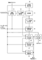
コンピュータシステム2は、コンピュータ本体21、キーボード22、ジョイスティックボックス(以下、J/Sと呼ぶ)23、マウス24及びCRT25を備えて構成されている。コンピュータ本体21は、例えば図2に示すように構成されている。即ち、CCDカメラ18から入力されるワーク12の画像情報は、インタフェース(以下、I/Fと呼ぶ)31を介して画像メモリ32に格納される。
The
また、図示しないCADシステムにより作成されるワーク12のCADデータは、例えば、CADデータによるオフラインティーチングが実行される場合、I/F33を介してCPU35に入力され、CPU35でビットマップの画像情報に展開された後、画像メモリ32に格納される。画像メモリ32に格納された画像情報は、表示制御部36を介してCRT25に表示される。
The CAD data of the
一方、キーボード22、J/S23、及びマウス24から入力されるコード情報及び位置情報は、I/F34を介してCPU35に入力される。CPU35は、ROM37に格納されたマクロプログラム及びHDD38からI/F39を介してRAM40に格納された測定実行プログラム、測定結果表示プログラム、パートプログラム生成プログラム、パートプログラム等に従って測定実行処理、パートプログラム作成、及び測定結果の表示処理等を実行する。
On the other hand, code information and position information input from the
CPU35は、測定実行処理に従って、I/F41を介して画像測定機1を制御する。HDD38は、CADデータ、測定実行プログラム、測定結果表示プログラム、パートプログラム等を格納する記録媒体である。RAM40は、各種プログラムを格納する他、各種処理のワーク領域を提供する。
The
図3は、パートプログラム生成装置の機能ブロック図である。ワーク12の画像は、画像取得部51によって撮影される。画像取得部51は、キーボード22、マウス24などの操作に基づいて、ワーク12の指定された範囲において、CCDカメラ18を駆動させて、複数枚の画像を撮影する。撮影されたワークの画像は、画像メモリ32に供給され、また、このワークの画像は、ワーク画像展開部52において、ラスタ画像及びベクタ画像の2つの形式に変換されて、それぞれ記憶部53に格納される。ワーク画像合成部54は、記憶部53に記憶された複数枚のワークの画像を一枚のワークの画像に合成する。座標系設定部55は、この一枚に合成されたワークの画像による座標系と、ワーク12の座標系とを一致させるための座標系設定を行う。また、特徴画像抽出部56は、記憶部53に格納されたワークの画像のうち、キーボード22、マウス24などの操作に基づいて、ワークの画像の一定の特徴を有する箇所を特徴画像として抽出する。測定条件設定部57は、後述するエッジ検出ツール等の種類を含む測定条件を設定する。パートプログラム生成部58は、測定条件設定部57で設定された測定条件に基づいて、特徴画像抽出部56により抽出された全ての特徴画像に対して測定条件を設定して、パートプログラムファイルを生成する。生成されたパートプログラムファイルは、パートプログラム編集部59で適宜編集処理される。生成及び編集されたパートプログラムファイルは、パートプログラム出力部60を介してHDD38等に格納される。
FIG. 3 is a functional block diagram of the part program generation device. The image of the
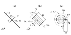
次に、図4乃至図6を参照して、パートプログラム生成装置において使用されるエッジ検出ツールを説明する。ここで、エッジ検出ツールとは、CRT25上に表示されたワークの画像に基づき、マウス操作により測定条件を決定可能とするものである。図4(a)は最もシンプルなツール(以下、シンプルツールと呼ぶ)71で、ワークを撮像して得られる画像情報72の濃度レベルが、矢印の基端から先端の間で急激に変化している点をエッジ点として検出するためのものである。このシンプルツール71は、中点の位置座標(X、Y)と、その長さWと、角度θとによって定義され、マウス操作のドラッグにより、ワークの画像の任意の箇所に配置可能である。同図(b)は、矩形の箱形のツール(以下、ボックスツールと呼ぶ)73で、直線画像情報72aの検出に適しており、中点の位置座標(X、Y)と、両側の矢印の長さWと、両側の矢印間の幅Hと、角度θとによって定義される。ボックスツール73の場合、幅Hの中に予め設定された間隔ΔHで、矢印の基端から先端に向かうエッジ検出が繰り返される。同図(c)は、円形のツール(以下、円ツールと呼ぶ)74で、円形画像情報72bの検出に適しており、位置座標(X、Y)と、測定を開始する内径r1と、測定を終了する外径r2によって定義される。円ツール74の場合、予め設定された角度Δθで、座標(X、Y)を中心として回転し、矢印の基端から先端に向かうエッジ検出が繰り返される。また、上記ボックスツール、円ツールの他に、円弧ツール等もある。これらツール71、73、74の全てのパラメータを図形要素毎に演算によって求めても良いが、演算処理が複雑になるので、ここではツール71、73、74の位置と傾きのみを、測定対象として選択された図形要素毎に演算して決定することにより、演算処理量を削減している。
Next, an edge detection tool used in the part program generation apparatus will be described with reference to FIGS. Here, the edge detection tool is a tool that allows measurement conditions to be determined by a mouse operation based on a workpiece image displayed on the
従って、エッジ検出ツールの設定においては、図形要素の種類(線、円、円弧等)毎に、エッジの種類(ツールタイプ)、数、長さW(画素数)、オフセット数のみを設定する。図5(a)は、矩形画像情報72cについて、シンプルツール71を適用し、数nが3で、上辺の両端からそれぞれOFFだけオフセットを設定し、図中Aの範囲をシンプルツール71の配置範囲として設定している例を示している。オフセットOFFを設定するのは、線や円弧の端部にシンプルツール71が配置されることによりエッジ検出不能のエラーが発生するのを回避するためである。オフセットOFFは、長さで設定しても良いし、線の長さのパーセントで設定するようにしても良い。同図(b)は、円形画像情報72bについて、4つのシンプルツール71を配置した例である。円形の場合には、オフセットは不要である。
Therefore, in setting the edge detection tool, only the edge type (tool type), number, length W (number of pixels), and number of offsets are set for each type of graphic element (line, circle, arc, etc.). In FIG. 5A, the
このようにして設定された内容を図6に示す。各図形要素について、そのツールタイプ、ツール数、長さW及びオフセットOFFがエッジ検出ツール生成条件として測定条件設定部59の中に設定される。この例では、1次候補だけでなく、1次候補のツールの生成に失敗した場合の他のツール候補も2次候補として設定されている。
The contents thus set are shown in FIG. For each graphic element, the tool type, the number of tools, the length W, and the offset OFF are set in the measurement
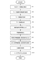
次に、図7、図8を参照して、上記のように構成された非接触画像測定システムにおけるパートプログラム生成手順について説明する。図7は、パートプログラムの自動生成処理の手順を示すフローチャートであり、図8は、例えば、BGAパッケージ等のワーク12を測定した場合の本実施形態に係る代表的なCRT25の表示例である。ここで、ワーク12は、球状に突出したボール部81を備えている。まず、キーボード22及びマウス24から、CPU35を介して、ワーク12を表示するように制御命令が出力されると、CCDカメラ18の撮像倍率を低倍率に切り替え、測定テーブル13に設置されたワーク12が撮影される。この映像の信号は、CCDカメラ18からI/F31、画像メモリ32、表示制御部36を介してCRT25に送られて、図8(a)に示すようなワーク12のズームアウトされた生の画像が表示される(S1)。ここで、照明については、キーボード22及びマウス24の入力により、垂直落射照明、透過照明、リングファイバ照明、プログラム制御リング照明等の照明の種類についての設定と、照明の光量設定(光なし(0%)から最大光(100%)まで)が可能である。レンズについては、固定倍率レンズ、プログラム制御パワーターレット、プログラム制御ズームレンズ等の数種のレンズについてのレンズ倍率の設定が可能である。
Next, a part program generation procedure in the non-contact image measurement system configured as described above will be described with reference to FIGS. FIG. 7 is a flowchart showing the procedure of the part program automatic generation processing, and FIG. 8 is a display example of a
また、CRT25にはマウスのポインタPが表示されており、オペレータは、例えば、図8(b)に示す82の位置にポインタPを移動させてマウス24をクリックし、次いでマウス24をドラッグしてポインタPを83の位置まで移動させて画像を四角形84により囲む。上記操作により、ティーチングの対象範囲すなわちパートプログラムを作成する測定対象範囲84の指定を行う(S2)。
In addition, a mouse pointer P is displayed on the
ティーチングの対象範囲の指定が完了すると、図8(c)に示すように、指定された測定対象範囲84の範囲を、多数の小範囲Dに分割して、矢印A方向に移動しながら、CCDカメラ18により撮影を行う。すなわち、1つの小範囲Dを撮影したら、その撮影位置でのCCDカメラ18のXY方向の位置を図示しない位置センサの出力に基づいて検知するとともにその位置データをその撮影画像に関連付けて記録する。その後、順次CCDカメラ18を矢印A方向に移動させ、指定された測定対象範囲84の範囲の撮影が終了するまで、同様に小範囲Dを撮影していく(S3)。なお、隣接する小範囲Dは、接合を行うため、所定の重複範囲を持つようにするのが好ましい。
When the designation of the teaching target range is completed, the designated
撮影が終了すれば、得られた小範囲Dの多数の画像を接合し、ワークの画像を合成する(S4)。上述のように、多数の小範囲Dの画像は重複範囲を持っている。この重複範囲に公知のパターンマッチング等の手法を適用することにより、この小範囲Dの画像を、測定対象範囲84の全範囲を含む1枚のワーク保存画像データ85として取得することができる。この1枚の大画面のワーク保存画像データ85を、撮像時のCCDカメラ18の位置(XY方向)、照明条件等と共にHDD38に保存する。接合する代わりに、CCDカメラ18の位置を検知する位置センサ(図示せず)からの位置データに基づいて、小範囲Dの画像間の位置関係を演算して保存させるようにしてもよい。
When the photographing is finished, a large number of images in the obtained small range D are joined, and a workpiece image is synthesized (S4). As described above, many small range D images have overlapping ranges. By applying a known method such as pattern matching to the overlapping range, the image of the small range D can be acquired as one piece of work-save
次に、オペレータは、ワーク保存画像データ85から一定の特徴を有する測定箇所を特徴画像として抽出するため、その測定箇所の特徴をキーボード22及びマウス24により入力する(S5)。図8の場合、抽出する対象は円形画像のボール部81であり、オペレータは、その円形画像に対応する画素数、及び輝度を有する連結成分を検出する制御命令をキーボード22及びマウス24により入力する。上記制御命令が入力されると、特徴画像抽出部56は、入力された画素数、及び輝度を有する連結成分、即ち、ボール部81の画像を特徴画像として抽出し、その抽出結果をCRT25上に、例えば図8(d)に示すように表示する(S6)。そして、抽出する対象が、円形のボール部81であることから、例えば、抽出された特徴画像に2値化処理を行った後、連結成分の特徴を解析し、連結成分の重心位置を算出し、これをボール部81の中心位置86とする。
Next, in order to extract a measurement location having a certain feature from the work
次に、任意の一つの特徴画像に対して測定条件を決定する(S7)。すなわち、キーボード22及びマウス24の入力により、エッジ検出ツールの種類の設定、配置するエッジ検出ツールの数の設定、エッジ検出ツールのサイズの設定、オフセット値等の設定を行う。図8(e)は、抽出された任意の一つの特徴画像、ここにおいては、ボール部81の画像に対して、上述した円ツール74が設定される例を示している。
Next, a measurement condition is determined for one arbitrary feature image (S7). That is, setting of the type of edge detection tool, setting of the number of edge detection tools to be arranged, setting of the size of the edge detection tool, setting of an offset value, and the like are performed by input from the
このように任意の一つの特徴画像にエッジ検出ツールが配置されると、つづいて、全てのボール部81を有する特徴画像の中心座標86に、前工程(S7)において設定した円ツール74が配置される(S8)。
When the edge detection tool is arranged in one arbitrary feature image as described above, the
次に、実際の測定データとワーク保存画像データ85との公差照合が行われる(S9)。本設定では、数種の公差に対応できるようになっており、例えば、上下限公差として、座標値、角度、距離に対して、設計値からの許容範囲を上限公差と下限公差で設定する。また、公差範囲として、位置度、形状(真直度、真円度等)に対して、公差域を設定する。また、この他はめ合い公差等についても公差情報の設定を行うことができ、これらの公差情報は公差リストとして保存することができる。また、前記公差情報の設定には、全ての測定対象図形に対して共通の公差情報を設定する方法と、普通公差ファイルによって設計値に合わせて公差情報を設定する方法の二つの設定方法が用意されている。公差情報を設定した後、これら設定条件に基づきパートプログラムが生成され(S10)、本プログラムは終了する。
Next, the tolerance comparison between the actual measurement data and the work
次に、図9を参照して、ワークが、例えばリードフレーム等である場合を説明する。図9に示すように、ワーク12’は、1つの矩形のダイパッド91と、ダイパッド91の近傍に末端が位置する複数のリード部92と、ダイパッド91に接続された4本のリード接続部93と、を有する。なお、図9に示す本制御は、マニュアル操作においてエッジ検出ツールの設定に時間を要する複数のリード部92のエッジを測定対象としている。この場合においても、図9(a)〜図9(c)に示す工程は、ワーク12のボール部81を測定した図8の例と同様に図7に示す手順で実行される。即ち、図9(a)に示すように、ワーク12’全体の生の画像を表示させる(S1)。次に、まず、図9(b)に示すように、マウス24のドラッグ操作により一定領域を四角形94で囲み、ティーチングの範囲を指定する(S2)。そして、図9(c)に示すように、CCDカメラ18を駆動して四角形94内即ち測定対象範囲内のワーク12’の画像を撮影して(S3)、一枚のワーク保存画像データ95に合成する(S4)。
Next, a case where the workpiece is, for example, a lead frame will be described with reference to FIG. As shown in FIG. 9, the
次に、リード部92を検出する制御命令をキーボード22及びマウス24により入力する(S5)。つづいて、この制御命令に基づき、図9(d)に示すように、ワーク保存画像データ95からリード部92が特徴画像として抽出される(S6)とともに、その中心線96の角度、及びその先端97の位置が算出される。ここで、図9(d)においては、特徴画像として抽出されるリード部92を実線で示し、特徴画像ではないダイパッド91及びリード接続部93を破線で示している。
Next, a control command for detecting the
リード部92及びその先端97の算出方法は、例えば、リード部92の画像を二値化し、リード部92の階調を1、リード部以外の背景部を0とする二値画像を得る。つづいて、8連結で線幅1の線図形を生成(Hilditchの細線化アルゴリズム等)し、その線図形を中心線96とする。つづいて、中心線96の8連結で連結度1となる画素を算出し、その連結度1となる画素をリード92の先端97とする。このように、中心線96の角度、及び先端97の位置を算出することが可能である。
The calculation method of the
次に、図9(e)に示すように、オペレータは、任意の選択した一つのリード部92にエッジ検出ツールを配置する(S7)。ここでは、リード部92に、マウス24の操作により矩形のボックスツール73a、73bが設定されている。つづいて、このように設定されたボックスツール73a、73bは、図9(d)に示された全ての特徴画像であるリード部92に対して同様に設定される(S8)。これら全てのリード部92に対するエッジ検出ツールの配置は、例えば、図9(e)に示すように、リード部92毎に、先端97を原点として、中心線96と、その中心線96に直交する軸98とからなる座標系(X’Y’)を設け、配置すべきボックスツール73a、73bの中心w1及びw2を算出することにより実行可能である。すなわち、任意に選択したリード部92に配置したエッジ検出ツールの位置をその座標系(X’、Y’)に基づき特定し、そのエッジ検出ツールの位置をその他全てのリード部92が有するそれぞれの座標系(X’、Y’)に割り当てることにより実行可能である。なお、図9(e)においてのエッジ検出ツールの配置は、一例であって、配置するエッジ検出ツールは、2つ以上であっても良く、ボックスツール73に限られることはない。
Next, as shown in FIG. 9E, the operator places an edge detection tool on one arbitrarily selected lead portion 92 (S7). Here,
上記のようにS8までのステップが完了すれば、図8の例と同様に公差値の設定が行われ(S9)、パートプログラムが生成される(S10)。 When the steps up to S8 are completed as described above, tolerance values are set in the same manner as in the example of FIG. 8 (S9), and a part program is generated (S10).
以上、発明の実施の形態を説明したが、本発明はこれらに限定されるものではなく、発明の趣旨を逸脱しない範囲内において種々の変更、追加、置換等が可能である。例えば、本実施例においては、ワークを撮影し、複数の画像を合成したワークの画像に基づき、パートプログラムを作成したが、撮影した一枚の画像のみであっても良く、或いは、予め用意された2次元CADデータに基づき、パートプログラムを作成することも可能である。 Although the embodiments of the invention have been described above, the present invention is not limited to these embodiments, and various modifications, additions, substitutions, and the like can be made without departing from the spirit of the invention. For example, in the present embodiment, a part program is created based on an image of a work obtained by photographing a work and combining a plurality of images. However, only one photographed image may be used or prepared in advance. It is also possible to create a part program based on the two-dimensional CAD data.
1…画像測定機、2…コンピュータシステム、3…プリンタ、11…架台、12、12’…ワーク、13…測定テーブル、14、15…支持アーム、16…X軸ガイド、17…撮像ユニット、18…CCDカメラ、19…位置センサ、21…コンピュータ本体、22…キーボード、23…ジョイスティックボックス、24…マウス、25…CRT、31、33、34、39、41…I/F、32…画像メモリ、35…CPU、36…表示制御部、37…ROM、38…HDD、40…RAM51…画像取得部、52…ワーク画像展開部、53…記憶部、54…ワーク画像合成部、55…座標系設定部、56…特徴画像抽出部、57…測定条件設定部、58…パートプログラム生成部、59…パートプログラム編集部、60…パートプログラム出力部。
DESCRIPTION OF
Claims (9)
前記ワークに対して領域を指定する領域指定手段と、
前記領域を複数の分割領域に分割する領域分割手段と、
それぞれの分割領域に移動して前記分割領域の位置情報を取得すると共に、それぞれの分割領域内の前記ワークを撮像して複数の第1ワーク画像を取得する撮像手段と、
前記位置情報をもとに複数の前記第1ワーク画像を接合することにより、第2ワーク画像を取得する画像接合手段と、
前記第2ワーク画像を表示する表示手段と、
前記第2ワーク画像から特定の特徴を有する特徴画像を抽出する特徴画像抽出手段と、
指定された前記特徴画像の少なくとも一つに測定条件を指定する測定条件指定手段と、
指定された前記測定条件を全ての前記特徴画像に割り当てる測定条件割当手段と
を備えたことを特徴とする画像測定装置用パートプログラム生成装置。 A part program generation device that is used in an image measurement device that measures a workpiece based on image data obtained by imaging the workpiece and generates a part program that describes a measurement procedure,
Area designating means for designating an area for the workpiece;
Area dividing means for dividing the area into a plurality of divided areas;
An image pickup unit that moves to each divided area to obtain position information of the divided area, and that takes an image of the workpiece in each divided area and obtains a plurality of first work images ;
Image joining means for obtaining a second workpiece image by joining a plurality of the first workpiece images based on the position information;
Display means for displaying the second work image ;
Feature image extraction means for extracting a feature image having a specific feature from the second work image ;
Measurement condition designating means for designating measurement conditions for at least one of the specified feature images;
A part program generation device for an image measurement device, comprising: measurement condition assignment means for assigning the designated measurement condition to all the feature images.
前記測定条件割当手段は、前記特徴画像の位置に基づき前記測定条件を割り当てる
ことを特徴とする請求項1又は2記載の画像測定装置用パートプログラム生成装置。 The feature image extraction means detects a position of the feature image ;
3. The image measurement device part program generation device according to claim 1 , wherein the measurement condition assigning unit assigns the measurement condition based on a position of the feature image .
前記測定条件割当手段は、前記特徴画像の図形角度に基づき前記測定条件を割り当てる
ことを特徴とする請求項1又は2記載の画像測定装置用パートプログラム生成装置。 The feature image extraction means detects a figure angle of the feature image ;
3. The image measurement device part program generation device according to claim 1 , wherein the measurement condition assigning unit assigns the measurement condition based on a graphic angle of the feature image .
前記ワークに対して領域を指定するステップと、
前記領域を複数の分割領域に分割するステップと、
それぞれの分割領域に移動して前記分割領域の位置情報を取得すると共に、それぞれの分割領域内の前記ワークを撮像して複数の第1ワーク画像を取得するステップと、
前記位置情報をもとに複数の前記第1ワーク画像を接合することにより、第2ワーク画像を取得するステップと、
前記第2ワーク画像を表示するステップと、
前記第2ワーク画像から特定の特徴を有する特徴画像を抽出するステップと、
指定された前記特徴画像の少なくとも一つに測定条件を指定するステップと、
指定された前記測定条件を全ての前記特徴画像に割り当てるステップと
を有することを特徴とする画像測定装置用パートプログラム生成方法。 A part program generation method for generating a part program that describes a measurement procedure and is used in an image measurement apparatus that measures a workpiece based on image data obtained by imaging the workpiece,
Designating an area for the workpiece;
Dividing the region into a plurality of divided regions;
Moving to each divided area to obtain position information of the divided area, capturing the work in each divided area and obtaining a plurality of first work images; and
Obtaining a second work image by joining a plurality of the first work images based on the position information;
Displaying the second work image ;
Extracting a feature image having a specific feature from the second work image ;
Designating measurement conditions for at least one of the designated feature images;
Assigning the designated measurement condition to all the feature images. A method of generating a part program for an image measurement device.
前記ワークに対して領域を指定するステップと、
前記領域を複数の分割領域に分割するステップと、
それぞれの分割領域に移動して前記分割領域の位置情報を取得すると共に、それぞれの分割領域内の前記ワークを撮像して複数の第1ワーク画像を取得するステップと、
前記位置情報をもとに複数の前記第1ワーク画像を接合することにより、第2ワーク画像を取得するステップと、
前記第2ワーク画像を表示するステップと、
前記第2ワーク画像から特定の特徴を有する特徴画像を抽出するステップと、
指定された前記特徴画像の少なくとも一つに測定条件を指定するステップと、
指定された前記測定条件を全ての前記特徴画像に割り当てるステップと
をコンピュータに実行させるよう構成されたことを特徴とする画像測定用パートプログラム生成用プログラム。 An image measurement part program generating program used for an image measuring apparatus for measuring a workpiece based on image data obtained by imaging the workpiece, and used for generating a part program describing a measurement procedure,
Designating an area for the workpiece;
Dividing the region into a plurality of divided regions;
Moving to each divided area to obtain position information of the divided area, capturing the work in each divided area and obtaining a plurality of first work images; and
Obtaining a second work image by joining a plurality of the first work images based on the position information;
Displaying the second work image ;
Extracting a feature image having a specific feature from the second work image ;
Designating measurement conditions for at least one of the designated feature images;
An image measurement part program generation program configured to cause a computer to execute the step of assigning the specified measurement condition to all the feature images.
前記測定条件を割り当てるステップは、前記特徴画像の位置に基づき前記測定条件を割り当てる
することを特徴とする請求項6又は7記載の画像測定装置用パートプログラム生成用プログラム。 Extracting the feature image includes detecting a position of the feature image ;
The program for generating a part program for an image measurement device according to claim 6 or 7 , wherein the step of assigning the measurement condition assigns the measurement condition based on a position of the feature image .
前記測定条件を割り当てるステップは、前記特徴画像の図形角度に基づき前記測定条件を割り当てる
ことを特徴とする請求項6又は7記載の画像測定装置用パートプログラム生成用プログラム。 Extracting the feature image includes detecting a graphic angle of the feature image ;
8. The program for generating a part program for an image measuring device according to claim 6 , wherein the step of assigning the measurement condition assigns the measurement condition based on a graphic angle of the feature image .
Priority Applications (1)
| Application Number | Priority Date | Filing Date | Title |
|---|---|---|---|
| JP2005262338A JP4932202B2 (en) | 2005-09-09 | 2005-09-09 | Part program generating apparatus for image measuring apparatus, part program generating method for image measuring apparatus, and part program generating program for image measuring apparatus |
Applications Claiming Priority (1)
| Application Number | Priority Date | Filing Date | Title |
|---|---|---|---|
| JP2005262338A JP4932202B2 (en) | 2005-09-09 | 2005-09-09 | Part program generating apparatus for image measuring apparatus, part program generating method for image measuring apparatus, and part program generating program for image measuring apparatus |
Publications (2)
| Publication Number | Publication Date |
|---|---|
| JP2007071835A JP2007071835A (en) | 2007-03-22 |
| JP4932202B2 true JP4932202B2 (en) | 2012-05-16 |
Family
ID=37933380
Family Applications (1)
| Application Number | Title | Priority Date | Filing Date |
|---|---|---|---|
| JP2005262338A Active JP4932202B2 (en) | 2005-09-09 | 2005-09-09 | Part program generating apparatus for image measuring apparatus, part program generating method for image measuring apparatus, and part program generating program for image measuring apparatus |
Country Status (1)
| Country | Link |
|---|---|
| JP (1) | JP4932202B2 (en) |
Cited By (2)
| Publication number | Priority date | Publication date | Assignee | Title |
|---|---|---|---|---|
| US10521923B2 (en) | 2016-03-16 | 2019-12-31 | Mitutoyo Corporation | Part program generating device of surface texture measuring apparatus |
| US10612917B2 (en) | 2016-03-16 | 2020-04-07 | Mitutoyo Corporation | Control method of surface texture measuring apparatus |
Families Citing this family (5)
| Publication number | Priority date | Publication date | Assignee | Title |
|---|---|---|---|---|
| JP5654801B2 (en) * | 2010-08-19 | 2015-01-14 | 株式会社ミツトヨ | Image measuring apparatus and image measuring method |
| JP5770486B2 (en) | 2011-02-21 | 2015-08-26 | 株式会社トプコン | All-around image measuring device |
| JP5947168B2 (en) * | 2012-09-14 | 2016-07-06 | 株式会社キーエンス | Appearance inspection apparatus, control method and program for appearance inspection apparatus |
| JP6008667B2 (en) * | 2012-09-14 | 2016-10-19 | 株式会社キーエンス | Appearance inspection apparatus, appearance inspection method and program |
| JP2020017111A (en) * | 2018-07-26 | 2020-01-30 | ファナック株式会社 | Work measurement device, work measurement method and program |
Family Cites Families (6)
| Publication number | Priority date | Publication date | Assignee | Title |
|---|---|---|---|---|
| JPH10283480A (en) * | 1997-03-31 | 1998-10-23 | Omron Corp | Recognition processor and storage medium for recognition processing applied for the same device |
| JP3924855B2 (en) * | 1997-08-19 | 2007-06-06 | 株式会社ニコン | Image measuring machine and method |
| JP2000124697A (en) * | 1998-10-15 | 2000-04-28 | Matsushita Electric Ind Co Ltd | Electrode height inspection method |
| JP2003058900A (en) * | 2001-08-20 | 2003-02-28 | Mitsutoyo Corp | Device for generating part program for image measuring instrument, and program |
| JP2003203216A (en) * | 2002-01-08 | 2003-07-18 | Mitsutoyo Corp | Image measuring device part program generating device and image forming device part program generating program |
| JP3922942B2 (en) * | 2002-03-06 | 2007-05-30 | 株式会社ミツトヨ | Image measuring apparatus, image measuring method, and image measuring program |
-
2005
- 2005-09-09 JP JP2005262338A patent/JP4932202B2/en active Active
Cited By (3)
| Publication number | Priority date | Publication date | Assignee | Title |
|---|---|---|---|---|
| US10521923B2 (en) | 2016-03-16 | 2019-12-31 | Mitutoyo Corporation | Part program generating device of surface texture measuring apparatus |
| US10612917B2 (en) | 2016-03-16 | 2020-04-07 | Mitutoyo Corporation | Control method of surface texture measuring apparatus |
| DE102017203530B4 (en) | 2016-03-16 | 2023-09-28 | Mitutoyo Corporation | Device for generating a part program of a device for measuring a surface condition |
Also Published As
| Publication number | Publication date |
|---|---|
| JP2007071835A (en) | 2007-03-22 |
Similar Documents
| Publication | Publication Date | Title |
|---|---|---|
| US6968080B2 (en) | Method and apparatus for generating part programs for use in image-measuring instruments, and image-measuring instrument and method of displaying measured results therefrom | |
| JP4932202B2 (en) | Part program generating apparatus for image measuring apparatus, part program generating method for image measuring apparatus, and part program generating program for image measuring apparatus | |
| JP4492654B2 (en) | 3D measuring method and 3D measuring apparatus | |
| JP5923824B2 (en) | Image processing device | |
| JP7167453B2 (en) | APPEARANCE INSPECTION SYSTEM, SETTING DEVICE, IMAGE PROCESSING DEVICE, SETTING METHOD AND PROGRAM | |
| JP2000346638A (en) | Method for generating measuring procedure file, measuring apparatus and storage medium | |
| US6600808B2 (en) | Part program generating apparatus and program for image measuring apparatus | |
| EP2387000B1 (en) | Image measuring apparatus, program, and teaching method of image measuring apparatus | |
| JP5467962B2 (en) | Measurement setting data creation device, measurement setting data creation method, program for measurement setting data creation device, and dimension measurement device | |
| JP3855244B2 (en) | Three-dimensional image recognition device using a microscope | |
| US7991219B2 (en) | Method and apparatus for detecting positions of electrode pads | |
| JP3672970B2 (en) | Non-contact image measurement system | |
| JP2011141807A (en) | Method and system for management of mill ends | |
| JP4812477B2 (en) | Image measurement device part program generation device, image measurement device part program generation method, and image measurement device part program generation program | |
| JP6300120B2 (en) | Control data generation method and control data generation apparatus | |
| JP2005030966A (en) | Inspection data setting method, and inspection method and device using it | |
| JP2003203216A (en) | Image measuring device part program generating device and image forming device part program generating program | |
| JP3589512B2 (en) | Inspection point marking method for microfabricated products, automatic dimension inspection method and automatic dimension inspection device | |
| JP7152973B2 (en) | Inspection condition creation support device, inspection condition creation support method, inspection condition creation support program, and recording medium | |
| JP3806269B2 (en) | Icon generating method, measuring apparatus, and storage medium | |
| JP2004239761A (en) | Image measuring instrument, and program for generating edge tracking measuring program | |
| JP7152972B2 (en) | Inspection condition creation support device, inspection condition creation support method, inspection condition creation support program, and recording medium | |
| JP2004078988A (en) | Instrument for measuring image, and method for displaying measured result | |
| JPH11281327A (en) | Method for measuring line width and device therefor | |
| JP6894590B2 (en) | Reference point identification device, machining program generation system, reference point identification method |
Legal Events
| Date | Code | Title | Description |
|---|---|---|---|
| A621 | Written request for application examination |
Free format text: JAPANESE INTERMEDIATE CODE: A621 Effective date: 20080808 |
|
| A977 | Report on retrieval |
Free format text: JAPANESE INTERMEDIATE CODE: A971007 Effective date: 20110525 |
|
| A131 | Notification of reasons for refusal |
Free format text: JAPANESE INTERMEDIATE CODE: A131 Effective date: 20110531 |
|
| A521 | Written amendment |
Free format text: JAPANESE INTERMEDIATE CODE: A523 Effective date: 20110728 |
|
| TRDD | Decision of grant or rejection written | ||
| A01 | Written decision to grant a patent or to grant a registration (utility model) |
Free format text: JAPANESE INTERMEDIATE CODE: A01 Effective date: 20120124 |
|
| A01 | Written decision to grant a patent or to grant a registration (utility model) |
Free format text: JAPANESE INTERMEDIATE CODE: A01 |
|
| A61 | First payment of annual fees (during grant procedure) |
Free format text: JAPANESE INTERMEDIATE CODE: A61 Effective date: 20120215 |
|
| R150 | Certificate of patent or registration of utility model |
Free format text: JAPANESE INTERMEDIATE CODE: R150 Ref document number: 4932202 Country of ref document: JP Free format text: JAPANESE INTERMEDIATE CODE: R150 |
|
| FPAY | Renewal fee payment (event date is renewal date of database) |
Free format text: PAYMENT UNTIL: 20150224 Year of fee payment: 3 |
|
| R250 | Receipt of annual fees |
Free format text: JAPANESE INTERMEDIATE CODE: R250 |
|
| R250 | Receipt of annual fees |
Free format text: JAPANESE INTERMEDIATE CODE: R250 |
|
| R250 | Receipt of annual fees |
Free format text: JAPANESE INTERMEDIATE CODE: R250 |