JP2005030966A - Inspection data setting method, and inspection method and device using it - Google Patents
Inspection data setting method, and inspection method and device using it Download PDFInfo
- Publication number
- JP2005030966A JP2005030966A JP2003271925A JP2003271925A JP2005030966A JP 2005030966 A JP2005030966 A JP 2005030966A JP 2003271925 A JP2003271925 A JP 2003271925A JP 2003271925 A JP2003271925 A JP 2003271925A JP 2005030966 A JP2005030966 A JP 2005030966A
- Authority
- JP
- Japan
- Prior art keywords
- image
- inspection
- sample
- data
- imaging
- Prior art date
- Legal status (The legal status is an assumption and is not a legal conclusion. Google has not performed a legal analysis and makes no representation as to the accuracy of the status listed.)
- Pending
Links
Images


Landscapes
- Length Measuring Devices By Optical Means (AREA)
- Length-Measuring Devices Using Wave Or Particle Radiation (AREA)
- Analysing Materials By The Use Of Radiation (AREA)
- Investigating Materials By The Use Of Optical Means Adapted For Particular Applications (AREA)
Abstract
Description
本発明は検査装置に関し、特に検査対象を複数の視野に分割して検査するための検査データ設定方法及びそれを使った検査方法並びに装置に関すものである。 The present invention relates to an inspection apparatus, and more particularly, to an inspection data setting method for inspecting an inspection object divided into a plurality of fields of view, and an inspection method and apparatus using the inspection data setting method.
欠陥検査装置や外観検査装置、寸法検査装置や線幅測定装置、及び画質検査装置、等の検査装置においては、従来、検査(測定)データとして、被検査対象物の検査エリア(以下、検査エリアと称する)の撮像視野毎に画像処理パラメータを設定していた。即ち、検査データとは、被検査対象物の検査エリア毎の対応する位置座標及びエリア座標、並びに、検査エリア毎の画像処理パラメータを含むデータである(例えば、特許文献1参照)。
そして、被検査対象の加工データや実装データ等の作成時に必要とされるため、この時点で作成されている等、撮像視野の位置や座標の情報が既に分かっている場合を除き、オペレータは実際の撮像位置に操作器を使って移動し、被検査対象である実際の試料を確認しながら位置や座標(以下、位置座標と称する)の登録を行う必要があった。撮像視野が既に分かっている場合とは、例えば、被検査対象物が部品実装基板であって、その部品実装基板に実装された部品の欠陥を検査する場合である。この場合、その部品実装基板に部品を実装するための部品実装データがあり、そのデータを参照すれば部品の検査エリアの位置座標が分かる。
In inspection apparatuses such as defect inspection apparatuses, appearance inspection apparatuses, dimension inspection apparatuses, line width measurement apparatuses, and image quality inspection apparatuses, conventionally, as inspection (measurement) data, an inspection area of an object to be inspected (hereinafter referred to as an inspection area). Image processing parameters are set for each imaging field of view. That is, the inspection data is data including the corresponding position coordinates and area coordinates for each inspection area of the object to be inspected, and image processing parameters for each inspection area (see, for example, Patent Document 1).
And since it is required when creating processing data, mounting data, etc. to be inspected, the operator actually does not know unless the information of the position and coordinates of the imaging field of view is already known. It is necessary to register the position and coordinates (hereinafter referred to as position coordinates) while confirming the actual sample to be inspected by moving to the imaging position using the operating device. The case where the imaging field of view is already known is, for example, a case where the object to be inspected is a component mounting board, and a component mounted on the component mounting board is inspected for defects. In this case, there is component mounting data for mounting the component on the component mounting board, and the position coordinates of the inspection area of the component can be known by referring to the data.
しかし、事前にそのような位置座標が分かるデータが無い場合には、被検査対象物の検査エリア毎に画像処理パラメータを設定する必要があった。例えば、上記の部品実装基板を被検査対象物としていても、異物検査や傷検査を目的とした検査や部品実装基板上または内部に形成された配線パターンや電極等の場合には、被検査対象物の検査したい場所(検査エリア)が部品搭載位置と無関係に存在することが多く、検査エリア毎に画像処理パラメータを設定する必要があった。
更に、欠陥検査装置や外観検査装置、寸法検査装置や線幅測定装置、及び画質検査装置、等の検査装置は、通常、微小欠陥や微細加工されたパターンの寸法、位置ずれ等を検出することを目的とする(例えば、特許文献2、特許文献3参照)。このため、検査エリア(即ち、検査したい場所)を拡大して、その拡大画像を使用して検査する。従って、1つの検査エリアが複数の撮像視野の画像に分割されることがあった。このように1つの検査エリアが複数の撮像視野に分割されるため、1つ1つの検査エリアに対応する検査データの設定作業が複雑なものとなっていた。なお、撮像視野の画像とは、拡大画像を取得する場合に、画像処理に必要な分解能(解像度)を有する最大の画像のことである。撮像視野とは、その視野画像が取得する被検査対象の領域のことである。
However, when there is no data for determining such position coordinates in advance, it is necessary to set an image processing parameter for each inspection area of the inspection object. For example, even if the above-mentioned component mounting board is the object to be inspected, in the case of inspection for the purpose of foreign object inspection or scratch inspection, wiring patterns or electrodes formed on or inside the component mounting board, the object to be inspected In many cases, a place (inspection area) where an object is to be inspected exists regardless of the component mounting position, and it is necessary to set an image processing parameter for each inspection area.
Furthermore, inspection devices such as defect inspection devices, appearance inspection devices, dimension inspection devices, line width measurement devices, and image quality inspection devices usually detect the size and displacement of micro-defects and micro-processed patterns. (For example, refer to
前述の従来技術には、位置座標が分かるデータが無い場合には、被検査対象物の検査エリア毎に位置座標データを入力してから、画像処理パラメータを設定しなければならない欠点があった。更にまた、1つの検査エリアが複数のエリア(視野領域)に分割されるため、検査データの設定作業が複雑なものになる欠点があった。
本発明の目的は、上記のような欠点を除去し、検査データを作成する過程で、位置座標データの入力を必要としないで画像処理パラメータを設定できる検査データ設定方法及びその方法を使った検査装置を提供することにある。
更に、検査実行時と同じ解像度(分解能)をもつようにするために、検査データ設定時に欠陥検出処理の試行が可能な画像を生成する検査データ設定方法及びその方法を使った検査装置を提供することにある。
The prior art described above has a drawback in that when there is no data for knowing the position coordinates, the image processing parameters must be set after inputting the position coordinate data for each inspection area of the inspection object. Furthermore, since one inspection area is divided into a plurality of areas (field-of-view areas), there is a disadvantage that the work of setting inspection data becomes complicated.
An object of the present invention is to eliminate the above-described drawbacks and in the process of creating inspection data, an inspection data setting method capable of setting image processing parameters without requiring input of position coordinate data, and inspection using the method To provide an apparatus.
Furthermore, in order to have the same resolution (resolution) as that at the time of inspection execution, an inspection data setting method for generating an image capable of trial of defect detection processing at the time of inspection data setting and an inspection apparatus using the method are provided. There is.
上記の目的を達成するため、本発明の検査データ設定方法は、試料の一部を撮像する撮像部と、撮像された該試料の画像の画像処理を行い試料の検査を行う検査装置であって、予め設定された検査データに基づいて検査を行う検査装置において、上記試料を撮像視野ごとに分割した画像で取込み、該分割した画像をつなぎ合せて1枚の画像を生成し、該生成された1枚の画像を表示し、該表示された画像に基づいて上記検査データの少なくとも1つを設定する。
また、本発明の検査方法は、試料の一部を撮像し、撮像された該試料の画像を画像処理し、該画像処理されたデータまたは上記撮像された該試料の画像の少なくともいずれかを表示し、予め設定された検査データに基づいて検査を行う検査方法において、上記表示部に表示された画像に基づいて上記検査装置を操作し、オペレータの指示に応じて、上記検査データを作成または変更する。
また、上記の目的を達成するため、本発明の検査装置は、少なくとも、試料の一部を撮像する撮像部と、撮像された該試料の画像を画像処理してその結果をデータとして画像処理部と、該画像処理部から出力されるデータまたは上記撮像された該試料の画像の少なくともいずれかを表示する表示部とを、少なくとも備え、予め設定された検査データに基づいて検査を行う検査装置において、上記表示部に表示された画像に基づいて上記検査装置を操作する操作手段を有し、該操作手段は、オペレータの指示に応じて、上記検査データを作成または変更する。
また、上記の目的を達成するため、本発明の検査装置の上記操作手段は、上記試料を撮像視野ごとに分割した画像で取込み、該分割した画像をつなぎ合せて1枚の画像を生成し、該生成された1枚の画像を表示し、該表示された画像に基づいて上記検査データの少なくとも1つを設定する。
In order to achieve the above object, an inspection data setting method of the present invention includes an imaging unit that images a part of a sample, and an inspection apparatus that performs image processing of the captured image of the sample and inspects the sample. In an inspection apparatus that performs inspection based on preset inspection data, the sample is captured as an image divided for each imaging field of view, and the divided images are joined to generate a single image. One image is displayed, and at least one of the inspection data is set based on the displayed image.
Further, the inspection method of the present invention images a part of a sample, performs image processing on the image of the imaged image, and displays at least one of the image-processed data and the imaged image of the sample. In the inspection method for performing inspection based on preset inspection data, the inspection apparatus is operated based on the image displayed on the display unit, and the inspection data is created or changed in accordance with an operator instruction To do.
In order to achieve the above object, an inspection apparatus according to the present invention includes at least an imaging unit that images a part of a sample, and an image processing unit that performs image processing on the captured image of the sample and uses the result as data. And a display unit that displays at least one of data output from the image processing unit or the captured image of the sample, and an inspection apparatus that performs inspection based on preset inspection data And operating means for operating the inspection apparatus based on the image displayed on the display unit, and the operating means creates or changes the inspection data in accordance with an instruction from the operator.
Further, in order to achieve the above object, the operation means of the inspection apparatus of the present invention takes the sample as an image divided for each imaging field of view and joins the divided images to generate one image, The generated image is displayed, and at least one of the inspection data is set based on the displayed image.
本発明によれば、検査エリアの設定時に、検査エリアが撮像視野をまたがっていても、操作者は撮像視野、ステージ座標を意識することなく本設定を行うことができる。
また、撮像視野を意識する必要がないことから従来、視野毎に設定していた検査データの設定をまとめて行うことが可能となる。
更に、拡大画像取得のため、全体が一度に撮像できない場合にも実行可能となる。
According to the present invention, when setting the inspection area, even if the inspection area extends over the imaging field of view, the operator can perform this setting without being aware of the imaging field of view and stage coordinates.
In addition, since it is not necessary to be aware of the imaging field of view, it is possible to collectively set inspection data that has been set for each field of view.
Furthermore, since the enlarged image is acquired, it can be executed even when the entire image cannot be captured at once.
本発明の検査データ設定方法及びそれを使った検査方法並びに装置の一実施形態は、欠陥検査装置や外観検査装置、寸法検査装置や線幅測定装置、及び画質検査装置、等の検査装置において、少なくとも被検査対象物である試料の一部を拡大撮影することができる撮像部と、撮像する試料の位置座標を変えるためのマニュピレータ(操作手段)を備える検査装置である。この検査装置は、例えば、撮像した画像に対して画像処理を行う機能を有し、また、マニュピレータをソフトウエアプログラムにより動作させる機能を有し、これらの機能を組合せることにより試料の所定の領域(検査エリア)を撮像した画像を判別し欠陥を検出することができる。
本発明の検査データ設定方法では、例えば、検査を行うための検査データを作成する過程で、試料全体の画像(全撮像視野画像)を撮像視野毎に分割して取込み、更にその画像をつなぎ合せて高分解能な1枚の画像を生成する。
この生成された1枚の画像(以下、生成画像と称する)に対して検査エリアの設定、画像処理パラメータの設定といった検査データ作成操作を行うため、検査エリアの位置座標を新たに入力しないで、検査エリアを設定または変更できる。即ち、オペレータが撮像視野の位置座標、サイズを意識する必要がない。更に、生成画像は、検査実行時と同じ解像度を持つために、データ設定時に欠陥検出処理の試行を行うことができる。
また、本発明の検査装置は、例えば、被検査対象の検査エリアの画像の再取込時及び検査実行時には検査エリアを含む撮像視野を自動的に計算して、検査対象となる撮像視野のみを取込み欠陥判定を行う。また、取込んだ複数の撮像視野の画像のつなぎ合わせ画像を生成して表示する。
An embodiment of an inspection data setting method and an inspection method and apparatus using the inspection data setting method of the present invention is an inspection apparatus such as a defect inspection apparatus, an appearance inspection apparatus, a dimension inspection apparatus, a line width measurement apparatus, and an image quality inspection apparatus. An inspection apparatus includes an imaging unit capable of enlarging and photographing at least a part of a sample that is an object to be inspected, and a manipulator (operation means) for changing position coordinates of the sample to be imaged. This inspection apparatus has, for example, a function of performing image processing on a captured image, and a function of operating a manipulator by a software program. By combining these functions, a predetermined region of a sample is obtained. It is possible to detect an image obtained by imaging the (inspection area) and detect a defect.
In the inspection data setting method of the present invention, for example, in the process of creating inspection data for performing an inspection, an image of the entire sample (entire imaging visual field image) is divided and captured for each imaging visual field, and the images are joined together. A high-resolution image.
In order to perform inspection data creation operations such as setting of an inspection area and setting of image processing parameters for this generated image (hereinafter referred to as a generated image), without newly inputting the position coordinates of the inspection area, The inspection area can be set or changed. That is, the operator does not need to be aware of the position coordinates and size of the imaging field of view. Further, since the generated image has the same resolution as that at the time of executing the inspection, it is possible to try the defect detection process at the time of data setting.
In addition, the inspection apparatus of the present invention automatically calculates an imaging field including the inspection area at the time of re-acquisition of an image of the inspection area to be inspected and execution of an inspection, for example, and only an imaging field to be inspected is obtained. Take in defects. Further, a stitched image of a plurality of captured image fields is generated and displayed.
本発明の検査データ設定方法は、例えば、試料全体を所定の複数の撮像視野のサイズに分割して撮像し、それら撮像した画像を、画像処理技術により並べてつなぎ合せて1枚の画像として生成する。即ち、この生成された1枚の画像(生成画像)は、検出精度に適合する分解能のエリア(撮像視野)に分割して撮像された画像を、1枚の画像となるようにつなぎ合せている。この生成画像の持つ分解能は、分割して撮像した画像1つずつの分解能と同じ分解能を有する。従って、この生成画像で画像処理パラメータの設定やティーチングを行うことが可能であり、撮像視野サイズを意識することなく作業が可能となる。
この生成画像に対して検査する範囲(検査エリア)の設定を行う。このとき操作者は検査視野のサイズや区分けを意識せずに操作できる。
また、検査を拡大画像で行うのであれば、撮像視野サイズに合せて分割して撮像されたそれら拡大画像を生成画像となるようにつなぎ合せる。従って、生成画像の持つ分解能は、拡大画像1枚毎の分解能と同じになる。
In the inspection data setting method of the present invention, for example, the entire sample is imaged by dividing it into a plurality of predetermined imaging fields of view, and the captured images are arranged and joined together by an image processing technique to generate one image. . That is, the generated image (generated image) is divided into an area (imaging field of view) with a resolution suitable for the detection accuracy, and the captured images are joined to form a single image. . The resolution of the generated image has the same resolution as that of each of the divided images. Therefore, it is possible to set image processing parameters and teach with this generated image, and work can be performed without being aware of the imaging field of view size.
The inspection range (inspection area) is set for the generated image. At this time, the operator can operate without being aware of the size and division of the inspection visual field.
Further, if the inspection is performed with an enlarged image, the enlarged images that are divided and imaged according to the imaging field size are connected to form a generated image. Therefore, the resolution of the generated image is the same as the resolution of each enlarged image.
図4は、試料 5 として電力増幅器の略構造を説明するための図で、試料の一例を説明するための図である。図4において、(a) は平面図で、(b) は (a) の 破線 g-g′での断面図である。 51 は電力増幅器、52 は無酸素銅等の金属放熱板、53 は配線基板、50-1 〜 50-5 は半導体チップで、50-1 と 50-2は FET( Field Effect Transistor )チップ、50-3 はダイオード( Di )チップ、54 は半導体チップ 50-1 〜 50-3 と金属放熱板を接着するはんだである。配線基板 53 の配線パターン、配線材、及び他の実装部品は省略している。
FIG. 4 is a diagram for explaining a schematic structure of a power amplifier as the
図4に示すように、半導体チップ 50-1 〜 50-3 は金属放熱板 52 に、はんだ 54 によって接着(ダイボンド)されている。この接着では、はんだ 54 に気泡が発生していないことが電力増幅器 51 の電気的特性、放熱性、信頼性等の品質に大きく影響するため、製造段階で、綿密に検査する必要がある。
As shown in FIG. 4, the semiconductor chips 50-1 to 50-3 are bonded (die-bonded) to the
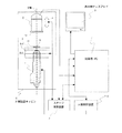
図1を用いて、本発明の検査装置の一実施例を説明する。図1は、本発明の検査装置の一実施例であり、半導体チップのダイボンド部分のボイド(気泡)を検出するための X 線検査装置の構成を示すブロック図である。 An embodiment of the inspection apparatus of the present invention will be described with reference to FIG. FIG. 1 is a block diagram showing the configuration of an X-ray inspection apparatus for detecting voids (bubbles) in a die bond portion of a semiconductor chip, which is an embodiment of the inspection apparatus of the present invention.
1 は X 線発生装置、11 は X 線発生装置 1 の先端部である。X 線発生装置 1 は、例えば、 X 線管である。2 は X 線カメラであり、2-1は X 線カメラ 2 の X 線イメージインテンシファイア(X 線蛍光増倍管、以下、X 線 II 管と称する)部で、2-2 は X 線カメラ 2 の CCD カメラ、12 は X 線 II 管部 2-1 の入力蛍光面である。3 は試料テーブルで、3-1 は X 軸試料ステージ、3-2 は Y 軸試料ステージである。4 は Z 軸移動機構で、撮像画像の拡大率を変えるために X 線カメラ 2 を上下方向に移動させる。5 は試料、6 は X 線防護キャビンであり、X 線の漏洩を防止するためのカバーである。また、X 線防護キャビン 6 は、真空状態近くの圧力に減圧するためのチャンバーの役割をも有する。
7 は制御用パーソナルコンピュータ(以下、制御用 PC と称する)、8 は制御用 PC 7 の表示用ディスプレイ、9 はステージ制御装置、10 は X 線制御装置である。
1 is the X-ray generator, and 11 is the tip of the
7 is a control personal computer (hereinafter referred to as a control PC), 8 is a display for the
X 線発生装置 1 は、先端部 11 から放射状に X 線を照射する。高電圧電源供給部、真空ポンプ系等、X 線発生装置 1 が動作するために必要な構成は本発明の説明には述べないので省略した。同様に、試料 5 を交換する機構についても説明を省略する。
The
X 線発生装置 1 の先端部 11 から照射された X 線は、放射状に広がりながら試料テーブル 3 とその試料テーブル 3 上に固定された試料 5 を透過して、その透過 X 線が、X 線 II 管部 2-1 の入力蛍光面 12 に到達する。
X 線 II 管部 2-1 は、入射した X 線を X 線の強度の差に対応した輝度差の光(可視光)に変換し、CCD カメラ 2-2 に出力する。CCD カメラ 2-2 は、入射した光を映像信号に変換して出力する。このように、X 線カメラ 2 は、被検査対象物を透過してきた X 線影像を撮像して出力する。
尚、図1の実施例では、X 線を可視光に変換するために、X 線イメージインテンシファイアを使用したが、シンチレータ等、X 線を可視光に変換するものであれば、何でも良いことは明らかである。
X-rays irradiated from the
X-ray II tube part 2-1 converts the incident X-rays into light with a luminance difference corresponding to the difference in X-ray intensity (visible light) and outputs it to CCD camera 2-2. CCD camera 2-2 converts the incident light into a video signal and outputs it. In this way, the
In the embodiment shown in FIG. 1, an X-ray image intensifier is used to convert X-rays into visible light. However, any device that converts X-rays into visible light, such as a scintillator, may be used. Is clear.
試料テーブル 3 は、X 軸と Y 軸から成る座標平面上を X 軸方向と Y 軸方向にそれぞれ移動する X 軸試料ステージ 3-1 と Y 軸試料ステージ 3-2 上に載せられ、試料テーブル 3 は試料 5 を試料テーブル 3 上に固定し、ステージ制御装置 9 からの制御に基づいて試料 5 の観察位置を変更するように移動する。ステージ制御装置 9 は、X 軸試料ステージ 3-1 と Y 軸試料ステージ 3-2 とを連動して、試料テーブルを所定の位置座標に動かすので、以降、X 軸試料ステージ 3-1 と Y 軸試料ステージ 3-2 とを総称して試料ステージと称する。また、ステージ制御装置 9 は、Z 軸移動機構 4 を制御して、X 線カメラ 2 ( CCD カメラ 2-2 と X 線 II 管部 2-1 )を Z 軸方向に動かし、入力蛍光面 12 を Z 軸方向に上下移動する。
Sample table 3 is placed on X-axis sample stage 3-1 and Y-axis sample stage 3-2 that move in the X-axis direction and Y-axis direction on the coordinate plane consisting of X-axis and Y-axis, respectively. Moves the
撮像倍率の変更の一実施例を、図3を用いて更に説明する。図3は、図1のX 線 II 管部 2-1 の入力蛍光面 12 と試料 5 及び、X 線発生装置 1 の先端部 11 を拡大して表示した図である。図3では、図1の試料テーブル 3 及び試料ステージは省略している。
An example of changing the imaging magnification will be further described with reference to FIG. FIG. 3 is an enlarged view of the
図1と図3において、ステージ制御装置 9 は、Z 軸移動機構 4 を制御して、X 線カメラ 2( CCD カメラ 2-2 と X 線 II 管部 2-1 )を Z 軸方向に動かし、試料 5 と入力蛍光面 12 との距離 B を変更し、試料 5 の撮像倍率を適宜変更する。このとき、X 線発生装置 1 の先端部 11 と観察試料面 14 との距離 A は固定である。
即ち、幾何学拡大率 GM は、式(1) によって算出することができる。式(1) において、Φ は、X 線 II 管部 2-1 の入力蛍光面 12 のサイズ径であり、例えば、Φ = 100 mm である。即ち、図3の(b) は図3の(a) の入力蛍光面 12 を X 線発生装置 1 側から見た概略図である。四角は、CCD カメラ 2-2 の X 線が入力される画面を表し、その画素サイズが横 Wx 、高さ Wy (例えば、横 640 画素、高さ 480 画素)に相当するサイズである。入力蛍光面 12 のサイズ径Φとは、この四角の対角線長さである。
1 and 3, the stage controller 9 controls the Z-
That is, the geometric enlargement ratio GM can be calculated by the equation (1). In Equation (1), Φ is the size diameter of the
また、Sx は試料観察面 14 の撮像視野の横幅であり、Sy は撮像視野の高さである。この撮像視野は、X 線発生装置 1 の先端部 11 と入力蛍光面 12 の外縁部とを結ぶ直線 13 が、観察試料面 14 と交差してできる四角形内の領域(エリア)である。

また、幾何学拡大率 GM は、式(2) のように、X 線発生装置 1 の先端部 11 と観察試料面 14 との距離 A と、X 線発生装置 1 の先端部 11 と入力蛍光面 12 との距離( A + B )の比で表すことができる。
尚、距離 A は、先端部 11 から試料 5 までの最小距離を FOD( Focus Object Distance )で、最小距離 FOD から実際の観察試料面 14 までの距離を t とすると、式(3) のように表すことができる。
また、距離 B は、最小先端部 11 と入力蛍光面 12 との最小距離を FFD( Focus Film Distance )、最小距離 FFD と実際の入力蛍光面 12 距離を Zp とすると、式(4) のように表すことができる。
図1、図3の実施例では、距離 A を固定し、距離 B を変更することによって拡大率を制御しているが、距離 A を変更することによっても良いし、距離 A と距離 B の両方を変更するようにしても良い。 In the embodiment of FIGS. 1 and 3, the distance A is fixed and the magnification B is controlled by changing the distance B. However, the distance A may be changed, or both the distance A and the distance B may be controlled. May be changed.
制御用 PC 7 は、予め設定された検査データに基づいて、X 線カメラ 2 から出力された映像信号を入力し、試料ステージの制御、Z 軸 移動機構 4 の制御、画像処理(例えば、画質改善、欠陥選出、判定、画像保存、等)、X 線発生装置 1 の制御、及び、オペレーションパネルの機能を有する。また、制御用 PC 7 は、内部に、検査データ他の各種データを保存するための記憶部を有するが、外部記憶装置を別に備え、必要なデータ(画像データを含む場合もある)の少なくとも1部を外部記憶装置に保存することも可能である。
また、制御用 PC 7 は、後述する方法等によって、新規に検査データを設定する他、予め設定された検査データの変更を行う。
The
Further, the
表示用ディスプレイ 8 は、制御用 PC 7 の表示用ディスプレイであり、検査データの設定時または変更時等、制御用PC 7 との GUI 操作や、入力手段(キーボード、マウス等のポインティングデバイス)を使ったオペレータとの対話、撮像した X 線透過画像、検査データ、等を必要に応じて表示する。
The display for
尚、図1の実施例では、制御用 PC 7 を用い、制御用 PC 7 とオペレータとの間での GUI 操作、例えば、入力手段(キーボード、マウス等のポインティングデバイス)を使ったオペレータとの対話形式での操作で説明したが、本発明はその他、ジョグコントローラ等のパーソナルコンピュータ制御専用の操作器(オペレーションパネル)を用いても良い。
尚、図1の説明では、制御用 PC 7 を用いたが、シーケンサ、CPU 、MPU 等による専用の操作制御手段を用いても本発明を実現できることは自明である。
In the embodiment shown in FIG. 1, the
In the description of FIG. 1, the
図2を用いて、本発明の検査データ設定方法の一実施例を説明する。図2の検査データ設定方法は、例えば、図1で述べた検査装置を使用して実行できる。従って、図2の実施例を図1の検査装置を参照して説明する。図2は、本発明の検査データ設定方法の一実施例の処理動作例を示すフローチャートである。
試料データ名入力ステップ 201 では、オペレータの入力によって検査対象となる試料の型式(識別番号)が入力されると、制御用PC 7 はその入力された型式を認識する。
型式判別ステップ 202 では、入力された試料の型式に該当する過去のデータが存在するか否かを判別する。もし、過去のデータが存在していれば試料データ読み込みステップ 206 に進み、過去のデータが存在していなければ新規試料データ入力ステップ 203 に進む。
An embodiment of the inspection data setting method of the present invention will be described with reference to FIG. The inspection data setting method in FIG. 2 can be executed using, for example, the inspection apparatus described in FIG. Accordingly, the embodiment of FIG. 2 will be described with reference to the inspection apparatus of FIG. FIG. 2 is a flowchart showing an example of processing operation of an embodiment of the inspection data setting method of the present invention.
In the sample data
In the
試料データ読込みステップ 206 では、既に登録されているデータの中から、試料の型式に該当するデータを選択して検査データとして読込み、撮像位置移動・画像取込みステップ 207 に進む。検査データとは、例えば、試料サイズ、検出最小欠陥サイズ、取込み基準位置(座標オフセット)、撮像視野サイズ、撮像視野数、撮像位置座標等である。
試料サイズ Ws は、図4において、電力増幅器 51 の横サイズ H 、縦サイズ V 、厚さ T である。撮像視野サイズは、図3(b) の撮像視野の横幅 Sx と高さ Sy であり、検出最小欠陥サイズ Dmin と CCD カメラ 2-2 の画像サイズ(画素数 Wx ,Wy )によって定まる(後述)。
In the sample
The sample size Ws is the horizontal size H, the vertical size V, and the thickness T of the power amplifier 51 in FIG. The imaging field size is the horizontal width Sx and height Sy of the imaging field in FIG. 3B, and is determined by the minimum detected defect size Dmin and the image size (number of pixels Wx, Wy) of the CCD camera 2-2 (described later).
新規試料データ入力ステップ 203 では、試料サイズ、最小欠陥検出サイズ Dmin 、取込み基準位置(座標オフセット)を入力し、画像視野サイズ・数算出ステップ 204 に進む。
次に、画像視野サイズ・数算出ステップ 204 では、最小検出欠陥サイズ Dmin より撮像視野サイズ Sx と Sy とを式(6) で求める。ここで、Sx は横方向のサイズ、Sy は高さ方向のサイズ、Ds は検査装置の分解能、Wx は CCD カメラ 2-2 の横方向の最大サイズ、Wy は CCD カメラ 2-2 の高さ方向の最大サイズである。
In the new sample
Next, in the image visual field size / number calculation step 204, the imaging visual field sizes Sx and Sy are obtained from the minimum detected defect size Dmin by Expression (6). Where Sx is the horizontal size, Sy is the height size, Ds is the resolution of the inspection device, Wx is the maximum horizontal size of CCD camera 2-2, and Wy is the height direction of CCD camera 2-2 Is the maximum size.
図5によって、撮像視野サイズの算出の方法を説明する。撮像視野サイズは、検出最小欠陥サイズDmin と CCD カメラ 2-2 の画像サイズ(画素数 Wx ,Wy )によって求められる。図5は、検出最小欠陥サイズ Dmin が 5 μm 、分解能 Ds が 10 のときの最小欠陥と画素サイズの関係を説明するための図である。 With reference to FIG. 5, a method of calculating the imaging visual field size will be described. The imaging field size is determined by the minimum detected defect size Dmin and the image size (number of pixels Wx, Wy) of the CCD camera 2-2. FIG. 5 is a diagram for explaining the relationship between the minimum defect and the pixel size when the detected minimum defect size Dmin is 5 μm and the resolution Ds is 10. FIG.
被検査対象を検査するときに要求される分解能 Ds が 10 であれば、検出最小欠陥サイズ(直径 5 μm )は 10 分割された値 0.5 μm が最小視野サイズとなる。従って、1画素当たり 0.5 μm としたときの画素数に相当するサイズが、撮像視野サイズとなる。即ち、画像サイズを横 640 画素、高さ 480 画素としたとき、横 640 × 0.5 = 320 μm 、高さ 480 × 0.5 = 240 μm が撮像視野サイズである。即ち、図5の格子それぞれが1画素分の画素サイズであり、例えば、CCD カメラ 2-2(または、入力蛍光面 12 のサイズ)の画像サイズが、640 × 480 画素( Wx × Wy = 640 × 480 )であれば、横方向にこの格子サイズが 640 個、高さ方向にこの格子サイズが 480 個並んだ画素数で撮像されることになる。
次に、幾何学拡大率 GM を式(2) によって算出する。
また、式(5) を変形することにより、Zp は式(7) のように表すことができる。従って、幾何学拡大率 GM が式(2)から求まれば、Zp が算出できる。
Further, Zp can be expressed as in Equation (7) by modifying Equation (5). Therefore, Zp can be calculated if the geometric enlargement ratio GM is obtained from equation (2).
図6は、図4の試料(電力増幅器 51 )について、複数の撮像視野に分割した例を示す図である。最初のステージ座標 Op( xoff ,yoff )から、横 Sx 、高さ Sy の長さ及び視野ピッチで破線の領域の撮像視野に分割されている。
尚、このとき各撮像視野のエリアは、周囲の撮像視野と重複させても良い。重複された領域、即ちオーバラップ部があると、視野ピッチはオーバラップ分だけ小さくなる。また、図6の例では、端部について検査漏れがないように、予め設定された値だけ、外側に大きく撮像視野が設定される。
FIG. 6 is a diagram showing an example in which the sample (power amplifier 51) in FIG. 4 is divided into a plurality of imaging fields. From the first stage coordinates Op (xoff, yoff), the image is divided into an imaged field of view of a broken line area with a length of horizontal Sx, a height of Sy, and a field pitch.
At this time, the area of each imaging field may overlap with the surrounding imaging field. If there is an overlapped area, that is, an overlap portion, the viewing pitch is reduced by the overlap. Further, in the example of FIG. 6, the imaging field of view is set larger on the outside by a preset value so that there is no inspection omission at the end.
次に撮像位置座標算出ステップ 205 では、撮像視野それぞれのステージ座標を計算し、撮像位置移動・画像取込みステップ 207 に進む。
撮像位置移動・画像取込みステップ 207 では、試料ステージを各撮像視野の該当するステージ座標に移動して画像取込みを行い、全視野撮像判定ステップ 208 に進む。
全視野撮像判定ステップ 208 では、試料 5 全体の画像(即ち、全撮像視野画像)を取込んだか否かを判定する。全撮像視野画像を取り込んでいない場合は、撮像位置移動・画像取込みステップ 207 に戻る。また、全撮像視野画像を取り込んだ場合には、画像生成処理ステップ 209 に進む。
画像生成処理ステップ 209 では、取込んだ全ての画像を並べてつなぎ合せる処理を行い、試料 5 全体を合せた1枚の画像として生成する。
Next, in imaging position coordinate
In the imaging position movement /
In the all-field imaging determination step 208, it is determined whether or not the
In the image
次に、生成画像表示ステップ 210 では、画像生成処理ステップ 209 で生成した1枚の画像をディスプレイ 8 に表示する。このとき、試料 5 全体を表示するため、所定の割合で画素の間引きを行い、間引きされた画像を表示する。ディスプレイ 8 に表示された画像は間引きされた画像だが、実際に1枚の画像として保持されたデータは、つなぎ合せる前の各分割された視野サイズでの画像(即ち、拡大された画像)の解像度(分解能)を有しているため、高い解像度での画像処理が実現できる。
Next, in the generated image display step 210, one image generated in the image
次に、検査エリア設定ステップ 211 では、型式判別ステップ 202 で新規(過去のデータが存在していない)と判定されているときには、検査エリアの設定を行う。また、型式判別ステップ 202 で過去のデータが存在していれば、読み込まれた既に設定されている検査エリアが表示され選択可能となる。
オペレータが検査エリアを指定または変更する場合は、ディスプレイ 8 の表示画面上を GUI 操作して行なう。例えば、検査エリアを四角形に設定するとして、マウスで、検査エリアとして設定したい四角形の左下隅の点から右上隅の点まで、表示画面上をドラックして行う。この指定されたエリアを制御用 PC 7 が認識して記憶する。オペレータは、既に設定されている検査エリアを見て変更を加えたい時には、変更したい検査エリアの四角形について、四角形の4隅の点または4辺をドラッグして変更する。
この検査エリアは、分割した複数の撮像視野を跨っていても良く、オペレータは撮像視野、ステージ座標を意識することなく本設定を行うことができる。
検査エリア設定ステップ 211 では、オペレータが検査エリアの設定された視野を認識し、制御用 PC 7 に記憶し、拡大表示判定ステップ 212 に進む。
Next, in the inspection area setting step 211, when it is determined in the
When the operator designates or changes the inspection area, the display screen of
This inspection area may straddle a plurality of divided imaging fields, and the operator can make this setting without being aware of the imaging field and stage coordinates.
In the inspection area setting step 211, the operator recognizes the field of view set in the inspection area, stores it in the
拡大表示判定ステップ 212 では、検査エリアの中から、オペレータが希望する検査エリアの拡大表示を行うか否かを判定する。この判定は、オペレータの指定による。例えば、オペレータが検査エリアの拡大をしない場合には、ディスプレイ 8 上に表示された拡大パスボタンをGUI 操作で押し、検査エリアの拡大をしたい場合には、ディスプレイ 8 上に表示された拡大ボタンをGUI 操作で押す。拡大パスボタンが押された場合には、設定終了ステップ 220 に進み、拡大ボタンが押された場合には、オペレータが検査エリアの拡大を指示したことを認識し、表示画面上には、検査エリア毎に設定する検出項目、画像処理パラメータ、判定パラメータを編集する為の選択ボタンを表示する。これらのボタンは、拡大ボタンと同時に表示されても良い。オペレータは、これらの中から必要なボタンを選択し、制御用 PC 7 がどれかのボタンが選択されたことを認識し、一部拡大表示ステップ 213 に進む。
尚、検査エリアが複数ある場合には、順番に検査エリアを表示するように、ディスプレイ 8 の表示画面上に操作ボタンを表示する。また、それぞれの検査エリアが識別できるように名称を付す。オペレータは操作ボタンを選択して操作を行う。以下同様に、ディスプレイ 8 の表示画面上にはその時々にオペレータが操作・入力するために必要な操作ボタンが表示される。
In the enlargement display determination step 212, it is determined whether or not to enlarge the inspection area desired by the operator from the inspection areas. This determination is based on an operator's designation. For example, if the operator does not enlarge the inspection area, press the enlargement path button displayed on the
When there are a plurality of inspection areas, operation buttons are displayed on the display screen of the
一部拡大表示ステップ 213 では、指定された検査エリア部分を拡大表示する。また、間引きが必要な場合はエリア全体が表示可能となるように、表示用の画像を作成するために、画素の間引きを行う。画素の間引きは、例えば、所定数おきに横方向と高さ方向の画素を除いて、表示用の画像を作成する。
次に、画像パラメータ設定・変更ステップ 214 では、検査エリア毎に設定する検出項目、画像処理パラメータ、判定パラメータを編集する。このとき画像生成処理ステップ 209 で生成した画像が検査を実行する際の拡大率で撮像されているので、その拡大率による解像度(分解能)での画像処理が実行可能となる。
In a partially enlarged display step 213, the designated inspection area portion is enlarged and displayed. Further, when thinning is necessary, pixel thinning is performed in order to create an image for display so that the entire area can be displayed. In the pixel thinning, for example, a display image is created by excluding pixels in the horizontal direction and the height direction every predetermined number.
Next, in the image parameter setting / changing step 214, detection items, image processing parameters, and determination parameters set for each examination area are edited. At this time, since the image generated in the image
次に、画像再取込み判定ステップ 215 では、再度検査エリアを含む撮像視野の画像を取込むか否かを判定する。即ち、オペレータは、一部拡大表示ステップ 213 で拡大表示された画像を見たときに、再度検査エリアを含む撮像視野の画像を取込むか否かを判断し、表示画面上の該当するボタンを押す。これらのボタンのいずれかが押されたかを制御用 PC 7 が認識することによって、画像の再取込みするか否かを選択する。
画像の再取込みと判定すれば、試料データ再読込みステップ 216 に進み、画像の再取込み要求無しと判定すれば、設定終了ステップ 220 に進む。この画像再取込みは、画像処理試行で再現性確認のために行う。
Next, in an image re-acquisition determination step 215, it is determined again whether or not an image of the imaging field including the examination area is captured. That is, when the operator sees the image magnified and displayed in the partially magnified display step 213, the operator determines again whether to capture the image of the imaging field of view including the examination area, and presses the corresponding button on the display screen. Push. The
If it is determined that the image is to be retaken, the process proceeds to step 216 for re-reading the sample data. This image re-acquisition is performed for reproducibility confirmation in an image processing trial.
試料データ再読込みステップ 216 では、再取込みを行う。即ち、再度撮像視野のステージ座標等のデータ(検査取込み視野(検査エリア)、撮像位置座標、等)を取得し、撮像位置移動・画像再取込みステップ 217 に進む。
撮像位置移動・画像再取込みステップ 217 では、試料ステージを各撮像視野の該当するステージ座標に移動して画像取込みを行い、全視野再撮像判定ステップ 218 に進む。
全視野再撮像判定ステップ 218 では、対象画像を取込んだかを判断する。未終了の場合は撮像位置移動・画像再取込みステップ217 繰り返し、終了の場合は、画像再生成処理ステップ209 に進む。
画像再生成処理ステップ 209 では、取込んだ隣接する画像をつなぎ合わせる処理を行い検査エリアの画像を、試料 5 全体を合せた1枚の画像として生成し、一部拡大表示ステップ 213 に進む。
一部拡大表示ステップ 213 では、既に指定された検出項目、画像処理パラメータ、判定パラメータによって再度、指定された検査エリア部分を拡大表示する。以下の処理は、既に説明した内容と同様である。
設定終了ステップ 220 では、全ての設定が終了したか否かを選択し、処理を繰返す場合は検査エリア設定ステップ 211 に戻り、終了する場合には、処理を終了する。処理の終了または否は、オペレータからの選択指示による。
In the sample
In the imaging position movement /
In the full-field
In the image
In the partially enlarged display step 213, the designated inspection area portion is enlarged and displayed again by the already designated detection item, image processing parameter, and determination parameter. The following processing is the same as that already described.
In the setting end step 220, it is selected whether or not all the settings are completed. If the process is repeated, the process returns to the inspection area setting step 211. If the process is ended, the process ends. Whether the process ends or not depends on a selection instruction from the operator.
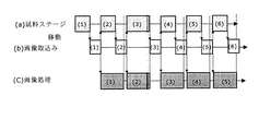
検査を実行する場合には、上記の検査データに基づいて、検査エリアが設定されている撮像視野のみの画像を取込み検査対象として欠陥検出及び判定を行う。図7と図6によって、検査の一実施例を説明する。
図7は、試料ステージ移動と画像取込み及び画像処理のタイミング例を示す図である。図6に示す各撮像視野に付した (1) 〜 (7) の場所が画像取込み場所、即ち検査エリアである。図7(a) は、試料ステージが移動している時間を示す。図7(b) は、画像を取込んでいる時間を示す。図7(c) は、画像処理している時間を示す。
まず試料ステージが、図7(a) において最初の視野画像 (1) のステージ座標に移動する。移動が終了した後、画像の取込みを行う。画像の取込みが終了した時点で、次の視野画像 (2) のステージ座標に移動すると共に、取込まれた視野画像 (1) の画像処理を行う。
次の視野画像 (2) のステージ座標に移動が終了した後、視野画像 (2) の画像の取込みを行う。画像の取込みが終了した時点で、次の視野画像 (3) のステージ座標に移動すると共に、取込まれた視野画像 (2) の画像処理を行う。
以下、同様に検査データで設定された通り、試料ステージの移動、視野画像の取得及び画像処理を全ての検査データとして設定された全ての視野画像について取得しながら、画像処理を行って、測定または検査を行う。尚、前の視野画像の画像処理が終了してから、次の視野画像の取込みが終了するようにタイミングが調整されている。
When the inspection is executed, based on the above inspection data, an image of only the imaging field of view in which the inspection area is set is captured, and defect detection and determination are performed as an inspection target. An example of the inspection will be described with reference to FIGS.
FIG. 7 is a diagram illustrating a timing example of sample stage movement, image capture, and image processing. The locations (1) to (7) attached to each imaging field shown in FIG. 6 are image capture locations, that is, inspection areas. FIG. 7A shows the time during which the sample stage is moving. FIG. 7B shows the time during which an image is captured. FIG. 7C shows the time during image processing.
First, the sample stage moves to the stage coordinates of the first visual field image (1) in FIG. After the movement is completed, the image is captured. When the image capture is completed, the stage coordinate of the next visual field image (2) is moved and image processing of the captured visual field image (1) is performed.
After moving to the stage coordinates of the next visual field image (2), the image of the visual field image (2) is captured. When the image capture is completed, the stage coordinate of the next visual field image (3) is moved and image processing of the captured visual field image (2) is performed.
Similarly, as set in the inspection data, the image processing is performed while acquiring the all the visual field images set as all the inspection data while moving the sample stage, acquiring the visual field images, and performing image processing. Perform an inspection. The timing is adjusted so that the capture of the next visual field image is completed after the image processing of the previous visual field image is completed.
また、表示用ディスプレイ 8 への取込み画像の表示や処理結果の表示は、必要に応じて行う。従って、1つの試料のすべての検査エリアについて画像処理が終了してから表示しても良いし、それぞれに結果が出たまたは検査で何らかの欠陥や測定データ等が得られた順に徐々に表示しても良い。
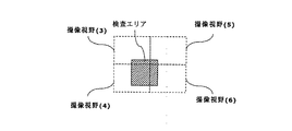
図8は、本発明の検査結果の表示の一実施例を示す図である。表示用ディスプレイ 8 には、例えば、図8の検査エリア部分だけを表示しても良いし、撮像視野 (3) 、撮像視野 (4) 、撮像視野 (5) 、撮像視野 (6) を順にまたは並べて一度に表示しても良い。また、他の検査エリアと同時に並べて表示しても良い。
In addition, display of captured images and display of processing results on the display for
FIG. 8 is a diagram showing an example of display of inspection results according to the present invention. On the
上述の実施例1〜3は、X 線検査装置について説明した。しかし、欠陥検査装置や外観検査装置、寸法検査装置や線幅測定装置、及び画質検査装置、等の検査装置全てにおいて、拡大画像を取得し画像処理によってまたは表示された画像を目視によって検査または測定する検査装置に適用できることは明らかである。また、このとき、特許文献1の第2頁及び第5図に示されるように、拡大手段として、投下型の顕微鏡(落射顕微鏡)を用い、被検査対象物からの反射光を拡大して撮像装置によって取得するような検査装置であっても良いことは自明である。
Examples 1 to 3 described above have described the X-ray inspection apparatus. However, in all inspection devices such as defect inspection devices, appearance inspection devices, dimension inspection devices, line width measurement devices, and image quality inspection devices, an enlarged image is acquired and image processing is performed or the displayed image is inspected or measured visually. It is clear that the present invention can be applied to an inspection apparatus. At this time, as shown in
また、上述の実施例1〜3では、検査装置において、拡大画像を取得し画像処理によってまたは表示された画像を目視によって検査または測定する検査装置について述べた。しかし、欠陥検査装置や外観検査装置、寸法検査装置や線幅測定装置、及び画質検査装置、等の検査装置全てにおいて、取得する画像が分解能に対応する倍率が拡大である必要は無く、等倍画像や縮小画像であっても、被検査対象に比べて一度に取得する画像が小さく、複数の画像の取得が必要である場合に、本発明の検査データ設定方法及びそれを使った検査方法並びに装置に適用できることは明らかである。 In the first to third embodiments, the inspection apparatus has been described in which an enlarged image is acquired and image processing is performed or the displayed image is inspected or measured in the inspection apparatus. However, in all inspection apparatuses such as a defect inspection apparatus, appearance inspection apparatus, dimension inspection apparatus, line width measurement apparatus, and image quality inspection apparatus, it is not necessary that the magnification corresponding to the resolution of the acquired image is enlarged. Even in the case of an image or a reduced image, when an image to be acquired at a time is small compared to an object to be inspected and it is necessary to acquire a plurality of images, the inspection data setting method of the present invention, an inspection method using the same, and Obviously, it can be applied to the device.
上記の実施例によれば、個別に取込んだ画像をつなぎ合わせて1枚の画像として生成し、この1枚の画像を対象に検査に必要な設定を行うことが可能となる。
これによって、検査エリアの設定時に、検査エリアが撮像視野をまたがっていても良く、オペレータは、撮像視野、ステージ座標を意識することなく設定を行うことができる。
また、撮像視野を意識する必要がないことから、従来、視野毎に設定していた検査データの設定をまとめて行うことが可能となる。
更に、生成した1枚の画像は、検査を実行する際の拡大率(即ち、分解能に見合った拡大、等倍、または縮小率)で撮像されているので、そのまま画像処理の実行が可能となる。例えば、拡大率を変更して試料全体を撮像した場合には検査時と解像度(分解能)が異なり検査を実行できないが、本実施例によれば、そのまま実行可能である。
更に、試料が大きく、分解能に見合った拡大、等倍、または縮小率では、全体が撮像できない場合にも対応可能である。
According to the above-described embodiment, it is possible to connect the individually captured images to generate a single image, and to perform settings necessary for the inspection with respect to the single image.
Thereby, when setting the inspection area, the inspection area may straddle the imaging field of view, and the operator can perform the setting without being aware of the imaging field of view and the stage coordinates.
In addition, since there is no need to be aware of the imaging field of view, it is possible to collectively set inspection data that has been set for each field of view.
Furthermore, since the generated single image is imaged at an enlargement rate at the time of executing the inspection (ie, enlargement, equal magnification, or reduction rate corresponding to the resolution), the image processing can be executed as it is. . For example, when the entire sample is imaged by changing the magnification rate, the resolution (resolution) is different from that at the time of the inspection, and the inspection cannot be executed. However, according to the present embodiment, it can be executed as it is.
Furthermore, it is possible to cope with a case where the entire sample cannot be imaged with a large sample and an enlargement, equal magnification, or reduction ratio corresponding to the resolution.
1:X 線管、 2:X 線カメラ、 2-1:X 線 II 管部、 2-2:CCD カメラ、 3:試料テーブル、 3-1:X 軸試料ステージ、 3-2:Y 軸試料ステージ、 4:Z 軸移動機構、 5:試料、 6:X 線防護キャビン、 7:制御用 PC、 8:表示用ディスプレイ、 9:ステージ制御装置、 10:X 線制御装置、 11:先端部、 12:入力蛍光面、 51:電力増幅器、 52:金属放熱板、 53:配線基板、 50-1 ,50-2 ,50-3:半導体チップ、 54:はんだ。
1: X-ray tube, 2: X-ray camera, 2-1: X-ray II tube, 2-2: CCD camera, 3: Sample table, 3-1: X-axis sample stage, 3-2: Y-axis sample Stage, 4: Z-axis movement mechanism, 5: Sample, 6: X-ray protective cabin, 7: Control PC, 8: Display for display, 9: Stage controller, 10: X-ray controller, 11: Tip, 12: Input phosphor screen, 51: Power amplifier, 52: Metal heat sink, 53: Wiring board, 50-1, 50-2, 50-3: Semiconductor chip, 54: Solder.
Claims (4)
上記試料を撮像視野ごとに分割した画像で取込み、
該分割した画像をつなぎ合せて1枚の画像を生成し、
該生成された1枚の画像を表示し、
該表示された画像に基づいて上記検査データの少なくとも1つを設定することを特徴とする検査データ設定方法。 In an imaging unit that images a part of a sample, and an inspection apparatus that performs image processing of the captured image of the sample and inspects the sample, in an inspection apparatus that performs inspection based on preset inspection data,
Capture the above sample with an image divided for each field of view,
Connect the divided images to generate one image,
Display the generated single image,
An inspection data setting method, wherein at least one of the inspection data is set based on the displayed image.
上記表示部に表示された画像に基づいて上記検査装置を操作し、オペレータの指示に応じて、上記検査データを作成または変更することを特徴とする検査方法。 A part of the sample is imaged, the captured image of the sample is image-processed, and at least one of the image-processed data or the captured image of the sample is displayed, and the inspection data set in advance is displayed. In the inspection method for performing the inspection based on
An inspection method comprising operating the inspection apparatus based on an image displayed on the display unit, and creating or changing the inspection data in accordance with an instruction from an operator.
上記表示部に表示された画像に基づいて上記検査装置を操作する操作手段を有し、
該操作手段は、オペレータの指示に応じて、上記検査データを作成または変更することを特徴とする検査装置。 An image capturing unit that captures at least a part of the sample, an image processing unit that performs image processing on the captured image of the sample, and uses the result as data, data output from the image processing unit, or the image captured In an inspection apparatus that includes at least a display unit that displays at least one of the images of the sample, and inspects based on preset inspection data,
Having an operation means for operating the inspection apparatus based on the image displayed on the display unit;
The operation device creates or changes the inspection data in accordance with an instruction from an operator.
上記操作手段は、上記試料を撮像視野ごとに分割した画像で取込み、該分割した画像をつなぎ合せて1枚の画像を生成し、該生成された1枚の画像を表示し、該表示された画像に基づいて上記検査データの少なくとも1つを設定することを特徴とする検査装置。
The inspection apparatus according to claim 3, wherein
The operation means captures the sample as an image divided for each imaging field of view, connects the divided images to generate one image, displays the generated one image, and displays the displayed image. An inspection apparatus, wherein at least one of the inspection data is set based on an image.
Priority Applications (1)
| Application Number | Priority Date | Filing Date | Title |
|---|---|---|---|
| JP2003271925A JP2005030966A (en) | 2003-07-08 | 2003-07-08 | Inspection data setting method, and inspection method and device using it |
Applications Claiming Priority (1)
| Application Number | Priority Date | Filing Date | Title |
|---|---|---|---|
| JP2003271925A JP2005030966A (en) | 2003-07-08 | 2003-07-08 | Inspection data setting method, and inspection method and device using it |
Publications (2)
| Publication Number | Publication Date |
|---|---|
| JP2005030966A true JP2005030966A (en) | 2005-02-03 |
| JP2005030966A5 JP2005030966A5 (en) | 2006-07-27 |
Family
ID=34209638
Family Applications (1)
| Application Number | Title | Priority Date | Filing Date |
|---|---|---|---|
| JP2003271925A Pending JP2005030966A (en) | 2003-07-08 | 2003-07-08 | Inspection data setting method, and inspection method and device using it |
Country Status (1)
| Country | Link |
|---|---|
| JP (1) | JP2005030966A (en) |
Cited By (8)
| Publication number | Priority date | Publication date | Assignee | Title |
|---|---|---|---|---|
| JP2008122097A (en) * | 2006-11-08 | 2008-05-29 | Hitachi Kokusai Electric Inc | Inspection measuring device |
| JP2009002712A (en) * | 2007-06-19 | 2009-01-08 | I-Bit Co Ltd | Die bonder apparatus |
| JP2009236632A (en) * | 2008-03-26 | 2009-10-15 | Panasonic Electric Works Co Ltd | X-ray foreign matter inspection device |
| JP2014055864A (en) * | 2012-09-13 | 2014-03-27 | Keyence Corp | Image measurement device, manufacturing method of the same and program for image measurement device |
| CN104583761A (en) * | 2012-08-28 | 2015-04-29 | 住友化学株式会社 | Defect inspection apparatus, and defect inspection method |
| CN104713481A (en) * | 2015-03-21 | 2015-06-17 | 江阴新杰科技有限公司 | Visual inspection method based on planar imaging technology |
| JP2015227809A (en) * | 2014-05-30 | 2015-12-17 | 住友ベークライト株式会社 | Inspection method of inspected object |
| JP2019124517A (en) * | 2018-01-15 | 2019-07-25 | 東芝Itコントロールシステム株式会社 | Radiation inspection device |
-
2003
- 2003-07-08 JP JP2003271925A patent/JP2005030966A/en active Pending
Cited By (10)
| Publication number | Priority date | Publication date | Assignee | Title |
|---|---|---|---|---|
| JP2008122097A (en) * | 2006-11-08 | 2008-05-29 | Hitachi Kokusai Electric Inc | Inspection measuring device |
| JP2009002712A (en) * | 2007-06-19 | 2009-01-08 | I-Bit Co Ltd | Die bonder apparatus |
| JP2009236632A (en) * | 2008-03-26 | 2009-10-15 | Panasonic Electric Works Co Ltd | X-ray foreign matter inspection device |
| CN104583761A (en) * | 2012-08-28 | 2015-04-29 | 住友化学株式会社 | Defect inspection apparatus, and defect inspection method |
| CN104583761B (en) * | 2012-08-28 | 2016-12-21 | 住友化学株式会社 | Flaw detection apparatus and defect detecting method |
| JP2014055864A (en) * | 2012-09-13 | 2014-03-27 | Keyence Corp | Image measurement device, manufacturing method of the same and program for image measurement device |
| JP2015227809A (en) * | 2014-05-30 | 2015-12-17 | 住友ベークライト株式会社 | Inspection method of inspected object |
| CN104713481A (en) * | 2015-03-21 | 2015-06-17 | 江阴新杰科技有限公司 | Visual inspection method based on planar imaging technology |
| JP2019124517A (en) * | 2018-01-15 | 2019-07-25 | 東芝Itコントロールシステム株式会社 | Radiation inspection device |
| JP7018770B2 (en) | 2018-01-15 | 2022-02-14 | 東芝Itコントロールシステム株式会社 | Radiation inspection equipment |
Similar Documents
| Publication | Publication Date | Title |
|---|---|---|
| JP5325580B2 (en) | Defect observation method and apparatus using SEM | |
| KR101342203B1 (en) | Method and device for testing defect using sem | |
| JP4866141B2 (en) | Defect review method using SEM review device and SEM defect review device | |
| US20190170659A1 (en) | Defect inspection device, defect inspection method, and program | |
| JP5066056B2 (en) | Sample observation method and electron microscope | |
| JP4586051B2 (en) | Scanning electron microscope | |
| US20210072165A1 (en) | Defect display device and method | |
| JP2006269489A (en) | Defect observation device and defect observation method using defect observation device | |
| JP2013171425A (en) | Image processing device | |
| JP5018868B2 (en) | Sample observation method and apparatus | |
| JP5390215B2 (en) | Defect observation method and defect observation apparatus | |
| JP4512471B2 (en) | Scanning electron microscope and semiconductor inspection system | |
| TWI390228B (en) | Semiconductor poor analytical devices, poor analytical methods, and poor analytical procedures | |
| TWI397105B (en) | Semiconductor poor analytical devices, poor analytical methods, and poor analytical procedures | |
| JP4932202B2 (en) | Part program generating apparatus for image measuring apparatus, part program generating method for image measuring apparatus, and part program generating program for image measuring apparatus | |
| JP2005030966A (en) | Inspection data setting method, and inspection method and device using it | |
| JP3361768B2 (en) | X-ray fluorescence analyzer and X-ray irradiation position confirmation method | |
| JP2008032754A (en) | X-ray fluoroscopic inspection apparatus | |
| JP6049052B2 (en) | Wafer visual inspection apparatus and sensitivity threshold setting method in wafer visual inspection apparatus | |
| JP4228773B2 (en) | Board inspection equipment | |
| JP4415285B1 (en) | Wire inspection apparatus, wire inspection method, and wire inspection program | |
| JP4072420B2 (en) | Calibration method for fluoroscopic inspection apparatus | |
| JPH08313217A (en) | Noncontact image measuring system | |
| JP7285988B2 (en) | Inspection device and inspection method | |
| JP2004233262A (en) | Measuring result displaying method, x-ray device and computer program |
Legal Events
| Date | Code | Title | Description |
|---|---|---|---|
| A521 | Written amendment |
Free format text: JAPANESE INTERMEDIATE CODE: A523 Effective date: 20060608 |
|
| A621 | Written request for application examination |
Free format text: JAPANESE INTERMEDIATE CODE: A621 Effective date: 20060608 |
|
| A977 | Report on retrieval |
Free format text: JAPANESE INTERMEDIATE CODE: A971007 Effective date: 20080711 |
|
| A131 | Notification of reasons for refusal |
Free format text: JAPANESE INTERMEDIATE CODE: A131 Effective date: 20081021 |
|
| A521 | Written amendment |
Free format text: JAPANESE INTERMEDIATE CODE: A523 Effective date: 20081219 |
|
| RD02 | Notification of acceptance of power of attorney |
Free format text: JAPANESE INTERMEDIATE CODE: A7422 Effective date: 20081219 |
|
| A02 | Decision of refusal |
Free format text: JAPANESE INTERMEDIATE CODE: A02 Effective date: 20090331 |