JP4914062B2 - Two-tiered retaining wall and its construction method - Google Patents
Two-tiered retaining wall and its construction method Download PDFInfo
- Publication number
- JP4914062B2 JP4914062B2 JP2005357607A JP2005357607A JP4914062B2 JP 4914062 B2 JP4914062 B2 JP 4914062B2 JP 2005357607 A JP2005357607 A JP 2005357607A JP 2005357607 A JP2005357607 A JP 2005357607A JP 4914062 B2 JP4914062 B2 JP 4914062B2
- Authority
- JP
- Japan
- Prior art keywords
- retaining wall
- mountain retaining
- mountain
- ground
- constructing
- Prior art date
- Legal status (The legal status is an assumption and is not a legal conclusion. Google has not performed a legal analysis and makes no representation as to the accuracy of the status listed.)
- Active
Links
Images


Landscapes
- Retaining Walls (AREA)
Description
本発明は、例えば、建物外周部に採光用スペース等に供されるドライエリアが形成され
、その内側に更に深い位置まで地下階が形成された建築物のように、地下躯体の下部深度
が外周部と内部で異なる建築物の地下工事に採用される二段山留め壁とその構築方法に関
する。
The present invention is such that, for example, a building in which a dry area provided for a daylighting space is formed on the outer periphery of a building, and a basement floor is formed to a deeper position on the inside thereof, the lower depth of the underground frame is the outer periphery. It is related with the two-tiered mountain retaining wall and its construction method used for underground construction of different buildings inside and outside.
地下躯体の下部深度が外周部と内部で異なる場合には、図7に示すように、山留め壁を
二段にすることがある。1は外側山留め壁、2は外側山留め壁1の内側に段差掘削部3を
隔てて構築された内側山留め壁である。地下水位Lが高い場合には、外側山留め壁1が遮
水壁となるように、外側山留め壁1として、止水性能が高いソイルセメント柱列壁などが
採用され、内側山留め壁としては、親杭横矢板壁などが採用される。
When the depth of the lower part of the underground frame is different between the outer peripheral part and the inside, as shown in FIG.
外側山留め壁1の水平抵抗もしくは根入れ部分の抵抗だけでは、側圧に耐えない場合、
支保工が用いられる。支保工としては、切梁を採用するよりも施工上及びコスト上有利で
、且つ、敷地に余裕のある場合には、例えば、図示のように、外側山留め壁1とその外側
に打設した控杭6をタイロッド7で連結する形式とされ、内側山留め壁2は地盤アンカー
9で支保される。
If the lateral resistance of the outer
A support is used. As for the support work, if it is more advantageous in terms of construction and cost than adopting a cut beam, and there is room in the site, for example, as shown in the figure, the outer
しかしながら、従来の二段山留め壁では、以下のような問題点がある。
(1)外側山留め壁1と内側山留め壁2の夫々を独立して設計・施工するためにオーバー
スペック(過剰品質)となり、不経済である。
(2)夫々の山留め壁1,2が平行してあることによる相乗効果が発揮できていない。例
えば、原地盤の地下水位が高く、図示のように、外側山留め壁1を遮水壁としてタイロッ
ド形式、内側山留め壁2を地盤アンカー形式とした場合、内側山留め壁2の地盤アンカー
9の定着部が遮水壁(外側山留め壁1)を貫通してしまい、止水性が確保できない。また
、地盤アンカー9の定着部と外側山留め壁1の芯材1aが干渉するため、芯材長さの設計
に制約がある。しかも、内側山留め壁2の内部地盤の掘削途中で地盤アンカー9の施工が
行われるので、工期が長くなり、コストが高く付く。
However, the conventional double-tiered retaining wall has the following problems.
(1) Since each of the outer
(2) The synergistic effect due to the fact that the mountain retaining
尚、特許文献1には、地盤掘削に伴って構築される開水構造の山留め壁と、この山留め
壁から所定距離背面側に離れた地盤内に造成された遮水壁とからなり、山留め壁と遮水壁
との間の地盤の地下水位をディープウエル等により低下させて、山留め壁の内側地盤を掘
削する二重の山留め構造が提案されている。この従来例は、地盤アンカーが遮水壁を貫通
していないが、山留め壁と遮水壁の間の地盤が掘削されず、段差掘削部が形成された二段
山留め壁(地下躯体の下部深度が外周部と内部で異なる建築物の地下工事に採用される二
段山留め壁)ではない。
本発明は、外側山留め壁と内側山留め壁の上端部とを鉄筋等の水平な連結材で繋いだ二
段山留め壁の地盤掘削に伴う挙動を検討し、その実測結果から、外側山留め壁の挙動は、
内側山留め壁の内部掘削に伴う地盤変位の影響とつなぎ鉄筋による引張り力の影響を考慮
することにより応力分布をほぼ評価でき、内側山留め壁は、二段山留め段差分の地盤を上
載荷重として考慮した背面側圧設定によりほぼ評価できるという事実を知見し、この新知
見に基づいて成されたものであって、内側山留め壁の内部掘削時に地盤アンカー等の支保
工を必要としないため、掘削工事を円滑に進めることができ、工期短縮とコスト低減を図
り得る二段山留め壁とその構築方法を提供することを課題とする。
The present invention examines the behavior associated with ground excavation of a two-stage mountain retaining wall in which the outer mountain retaining wall and the upper end of the inner mountain retaining wall are connected by a horizontal connecting material such as a reinforcing bar, and from the measurement results, the behavior of the outer mountain retaining wall is investigated. Is
The stress distribution can be almost evaluated by considering the effect of ground displacement due to the internal excavation of the inner retaining wall and the effect of the tensile force by the connecting rebar, and the inner retaining wall considers the ground for the two-step retaining structure as an overload. The fact that it can be almost evaluated by setting the pressure on the back side was founded, and it was made based on this new knowledge. Since excavation of the inner retaining wall is not required, support work such as ground anchors is not required. It is an object of the present invention to provide a double-stage mountain retaining wall and a method for constructing it that can reduce the work period and cost.
上記の課題を解決するために、本発明が講じた技術的手段は、次の通りである。即ち、
請求項1に記載の発明による二段山留め壁は、外側山留め壁の上下方向中間部とその内側
に段差掘削部を隔てて構築された内側山留め壁の上端部とを引張り力を負担可能な連結材
で連結してあることを特徴としている。
In order to solve the above-mentioned problems, technical measures taken by the present invention are as follows. That is,
The two-stage mountain retaining wall according to the first aspect of the present invention is a connection that can bear a tensile force between the vertical middle portion of the outer mountain retaining wall and the upper end portion of the inner mountain retaining wall that is constructed with a step excavation portion therebetween. It is characterized by being connected with materials.
請求項2に記載の発明による二段山留め壁の構築方法は、請求項1に記載の二段山留め
壁を構築する方法であって、外側山留め壁の上下方向中間部とその内側に段差掘削部を隔
てて構築された内側山留め壁の上端部とを引張り力を負担可能な連結材で連結した後、内
側山留め壁の内部地盤を掘削することを特徴としている。
A method for constructing a two-level mountain retaining wall according to
尚、請求項2に記載の二段山留め壁の構築方法において、外側山留め壁としては、新設
される場合と、既設の山留め壁を利用する場合とがある。
In addition, in the construction method of the two-stage mountain retaining wall according to
請求項3に記載の発明は、前者の場合であり、請求項2に記載の二段山留め壁の構築方
法であって、外側山留め壁を構築した後、外側山留め壁の内部地盤を内側山留め壁の上端
レベルまで掘削し、外側山留め壁の上下方向中間部と内側山留め壁の上端部とを引張り力
を負担可能な連結材で連結した後、内側山留め壁の内部地盤を掘削することを特徴として
いる。
The invention according to
請求項4に記載の発明は、後者の場合であり、請求項2に記載の二段山留め壁の構築方
法であって、既設の外側山留め壁の上下方向中間部とその内側に段差掘削部を隔てて構築
された内側山留め壁の上端部とを引張り力を負担可能な連結材で連結した後、内側山留め
壁の内部地盤を掘削することを特徴としている。この場合、請求項5に記載の発明のよう
に、解体された既存建物の基礎底盤の補強鉄筋と内側山留め壁の芯材を溶接等により連結
し、引張り力を負担可能な連結材として、解体された既存建物の基礎底盤を使用すること
ができる。
The invention described in
However, the foundation floor of the existing building that has been demolished can be used as a connecting material that can bear the tensile force .
請求項1,2に記載の発明によれば、内側山留め壁の上端部が引張り力を負担可能な連
結材によって外側山留め壁の上下方向中間部に繋がれているため、内側山留め壁の変形を
抑制しつつ内側山留め壁の内部地盤を掘削でき、内側山留め壁の内部掘削時に地盤アンカ
ー等の支保工を必要としないため、掘削工事を円滑に進めることができ、工期短縮とコス
ト低減を図り得る。
According to invention of
また、内側山留め壁の内部掘削時に地盤アンカーが不要であるから、地盤アンカーの定
着部が遮水壁としての外側山留め壁を貫通して止水性が確保できなくなったり、地盤アン
カーの定着部と外側山留め壁の芯材が干渉して、芯材長さの設計が制約されるといった問
題の発生を回避できる。
In addition, since ground anchors are not required when excavating the inner retaining wall, the anchoring part of the ground anchor cannot penetrate the outer retaining wall as a water-impervious wall and cannot secure water sealing, or the anchoring part of the ground anchor Occurrence of the problem that the core material of the retaining wall interferes and the design of the core material length is restricted can be avoided.
連結材としては、要求される引張り力を負担し得るものであれば、鉄筋、鉄骨、鉄筋コ
ンクリートなど様々な仕様を選定することが可能であり、例えば、鉄筋とコンクリートで
内,外側山留め壁を連結し、一体化させて剛性を高め、この鉄筋コンクリート造の連結材
を内,外側山留め壁間の段差掘削部に位置する鉄筋コンクリート造の通路や床面に兼用す
る等して、山留めの合理化を図ることができる。また、外側山留め壁と内側山留め壁を一
体の山留め壁として設計・施工することにより、外側山留め壁の上下長さを低減すること
が可能であり、夫々を独立して設計・施工する場合のようなオーバースペック(過剰品質
)となることを回避できて、経済的である。
As the connecting material, various specifications such as rebar, steel frame, reinforced concrete can be selected as long as it can bear the required tensile force. For example, the inner and outer mountain retaining walls are connected with rebar and concrete. To increase the rigidity of the reinforced concrete structure, and streamline the retaining by using this reinforced concrete connecting material as a reinforced concrete passage or floor located at the step excavation between the inner and outer retaining walls. Can do. Also, by designing and constructing the outer and inner retaining walls as a single retaining wall, the vertical length of the outer retaining wall can be reduced, as in the case of designing and constructing each independently. It is economical because it can avoid excessive overspec (excessive quality).
請求項3に記載の発明によれば、外側山留め壁の構築、外側山留め壁の内部地盤を内側
山留め壁の上端レベルまで掘削することによる段差掘削部の形成、引張り力を負担可能な
連結材による外側山留め壁の上下方向中間部と内側山留め壁の上端部との連結、内側山留
め壁の内部地盤の掘削といった手順により、請求項1に記載の二段山留め壁を構築できる
。
According to the invention described in
請求項4に記載の発明によれば、外側山留め壁として既設の山留め壁を利用するので、
既存建物を解体撤去して新しい建築物(地下躯体の下部深度が外周部と内部で異なる建築
物)を建設する場合、外側山留め壁の構築の工程、費用が省略されることになり、非常に
経済的である。
According to the invention of
When dismantling the existing building and constructing a new building (a building where the depth of the lower part of the basement is different from that of the outer periphery and the inside), the construction process and cost of the outer retaining wall will be omitted. Economical.
殊に、請求項5に記載の発明によれば、外側山留め壁の上下方向中間部と新たに構築さ
れた内側山留め壁の上端部とを連結する引張り力を負担可能な連結材として、解体された
既存建物の基礎底盤を利用するので、一層経済的である。
In particular, according to the invention described in
以下、本発明の実施形態を図面に基づいて説明する。図1は、二段山留め壁の一例を示
す。図1において、1は外側山留め壁、2は外側山留め壁1の内側に段差掘削部3を隔て
て構築された内側山留め壁である。外側山留め壁1及び内側山留め壁2としては、地中連
続壁、柱列壁、親杭横矢板壁などを適宜選択できるが、図示の例では、地下水位Lが高い
ため、外側山留め壁1が遮水壁となるように、外側山留め壁1として、止水性能が高いソ
イルセメント柱列壁が採用されており、内側山留め壁2としては、親杭横矢板壁が採用さ
れている。1aは芯材(例えばH鋼)、2aは親杭となる芯材(例えばH鋼)である。
Hereinafter, embodiments of the present invention will be described with reference to the drawings. FIG. 1 shows an example of a two-level mountain retaining wall. In FIG. 1,
外側山留め壁1の上下方向中間部と内側山留め壁2の上端部とは連結材4で連結されて
いる。連結材4としては、要求される引張り強度を負担し得るものであれば、鉄筋、鉄骨
、鉄筋コンクリートなど様々な仕様を選定することが可能である。この例では、連結材4
として鉄筋が使用されており、図3に示すように、鉄筋の一端部を直角に折曲加工して、
その折曲部分を芯材1aのフランジ中央部に溶接し、鉄筋の他端部を芯材2aのウエブに
溶接してある。連結材(鉄筋)4は、内側山留め壁2の親杭となる芯材2a毎に設けられ
ている。5は連結材4が埋め込まれた状態に打設されたコンクリートであり、連結材4を
保護している。連結材4を鉄筋コンクリート造として、内,外側山留め壁1,2間の段差
掘削部3に位置する鉄筋コンクリート造の通路や床面に兼用することもできる。
The intermediate portion in the vertical direction of the outer
As shown in Fig. 3, one end of the reinforcing bar is bent at a right angle,
The bent portion is welded to the center of the flange of the
外側山留め壁1は、その外側に打設した控杭6とタイロッド7で連結することによって
支保されているが、切梁形式による支保工を選択してもよく、外側山留め壁1の横抵抗が
十分に大きければ、これらの支保工を省略してもよい。
The
図2は、本発明の他の実施形態を示す。この二段山留め壁は、地下水位Lがさほど高く
なく、湧水があっても段差掘削部3に排水溝を形成する等して湧水を排水処理できるため
、外側山留め壁1として親杭横矢板壁を採用し、内側山留め壁2としてソイルセメント柱
列壁を採用した点に特徴がある。その他の構成は、図1、図3の実施形態と同じであるた
め、同一構成部材に同一符号を付し、説明を省略する。
FIG. 2 shows another embodiment of the present invention. This two-stage mountain retaining wall has a groundwater level L that is not so high, and even if there is spring water, the spring water can be drained by forming a drainage groove in the
上記の構成によれば、内側山留め壁2の上端部が連結材4によって外側山留め壁1の上
下方向中間部に繋がれているため、内側山留め壁2の変形を抑制しつつ内側山留め壁2の
内部地盤を掘削でき、内側山留め壁2の内部掘削時に地盤アンカー等の支保工を必要とし
ないため、掘削工事を円滑に進めることができ、工期短縮とコスト低減を図り得る。
According to said structure, since the upper end part of the inner
また、内側山留め壁2の内部掘削時に地盤アンカーが不要であるから、地盤アンカーの
定着部が遮水壁としての外側山留め壁1を貫通して止水性が確保できなくなったり、地盤
アンカーの定着部と外側山留め壁1の芯材1aが干渉して、芯材長さの設計が制約される
といった問題の発生を回避できる。
In addition, since the ground anchor is not required when excavating the
外側山留め壁1と内側山留め壁2を一体の山留め壁として設計・施工することにより、
外側山留め壁1の上下長さを低減することが可能であり、夫々を独立して設計・施工する
場合のようなオーバースペック(過剰品質)となることを回避できて、経済的である。
By designing and constructing the
It is possible to reduce the vertical length of the outer
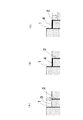
図4は、図1、図2に示した二段山留め壁の構築方法を示し、図4の(A)に示すよう
に、外側山留め壁1を構築した後、外側山留め壁1の内部地盤を内側山留め壁2の上端レ
ベルまで掘削して、段差掘削部3を形成し、図4の(B)に示すように、外側山留め壁1
の上下方向中間部と内側山留め壁2の上端部とを連結材4で連結した後、図4の(C)に
示すように、内側山留め壁2の内部地盤を掘削して、図1、図2に示した二段山留め壁を
構築している。内側山留め壁2は段差掘削部3の形成後、構築されるのが普通であるが、
外側山留め壁1の内部地盤の掘削に先立って造成しておくことも可能である。
FIG. 4 shows a construction method of the two-stage mountain retaining wall shown in FIGS. 1 and 2. After the outer
1 and the upper end of the
It is also possible to create the outer
図5は、図1、図2に示した二段山留め壁を構築する他の構築方法を示す。この構築方
法は、外側山留め壁1として、既設の山留め壁を利用する点に特徴がある。即ち、図5の
(A)に示すように、既設の山留め壁aを残置させた状態に、既存建物8を解体撤去する
ことにより、既設の山留め壁aを外側山留め壁1として使用し、必要があれば、外側山留
め壁1の内部地盤を内側山留め壁2の上端レベルまで掘削して、段差掘削部3を形成し、
次に、図5の(B)に示すように、外側山留め壁1の上下方向中間部と内側山留め壁2の
上端部とを連結材4で連結した後、図4の(C)に示すように、内側山留め壁2の内部地
盤を掘削して、図1、図2に示した二段山留め壁を構築している。
FIG. 5 shows another construction method for constructing the two-level mountain retaining wall shown in FIGS. 1 and 2. This construction method is characterized in that an existing mountain retaining wall is used as the outer
Next, as shown in FIG. 5B, the vertical intermediate portion of the
この構成によれば、外側山留め壁1として既設の山留め壁aを利用するので、既存建物
8を解体撤去して新しい建築物(地下躯体の下部深度が外周部と内部で異なる建築物)を
建設する場合、外側山留め壁1の構築の工程と費用が省略されることになり、非常に経済
的である。
According to this configuration, since the existing mountain retaining wall a is used as the outer
図6は、図1、図2に示した二段山留め壁を構築する他の構築方法を示す。この構築方
法は、外側山留め壁1として、既設の山留め壁aを利用し、連結材4として既存建物8の
基礎底盤bを利用する点に特徴がある。即ち、図6の(A)に示すように、既設の山留め
壁aと基礎底盤bを残置させた状態に、既存建物8を解体撤去することにより、既設の山
留め壁aを外側山留め壁1として使用し、図6の(B)に示すように、基礎底盤bを貫通
する状態に内側山留め壁2を構築し、基礎底盤bの補強鉄筋と内側山留め壁2の芯材2a
を溶接する等して、内側山留め壁2より外側に位置する基礎底盤bを外側山留め壁1の上
下方向中間部と内側山留め壁2の上端部とを連結する連結材4として利用し、しかる後、
図6の(C)に示すように、内側山留め壁2の内部地盤を掘削して、図1、図2に示した
二段山留め壁を構築している。
FIG. 6 shows another construction method for constructing the two-level mountain retaining wall shown in FIGS. 1 and 2. This construction method is characterized in that the existing mountain retaining wall a is used as the outer
Is used as a connecting
As shown in FIG. 6C, the inner ground of the inner
この構成によれば、既設の山留め壁aを外側山留め壁1として利用するだけでなく、既
存建物8の基礎底盤bを連結材4として利用するので、連結材4の工程が省略ないし簡略
化されることになり、一層経済的である。
According to this configuration, not only the existing mountain retaining wall a is used as the outer
以上、図1〜図6に基づいて本発明の実施形態を説明したが、本発明は図示した構成の
みに限定されるものではなく、本発明の要旨を逸脱しない範囲において、種々なる態様で
実施し得ることは勿論である。
Although the embodiment of the present invention has been described based on FIGS. 1 to 6, the present invention is not limited to the illustrated configuration, and can be implemented in various modes without departing from the gist of the present invention. Of course you can.
1 外側山留め壁
2 内側山留め壁
3 段差掘削部
4 連結材
a 既設の山留め壁
b 既存建物の基礎底盤
DESCRIPTION OF
Claims (5)
壁の上端部とを引張り力を負担可能な連結材で連結してあることを特徴とする二段山留め
壁。 A two-stage mountain retaining structure characterized in that an intermediate portion in the vertical direction of the outer retaining wall and an upper end portion of the inner retaining wall constructed with a step excavation portion inside are connected by a connecting material capable of bearing a tensile force. wall.
部とその内側に段差掘削部を隔てて構築された内側山留め壁の上端部とを引張り力を負担
可能な連結材で連結した後、内側山留め壁の内部地盤を掘削することを特徴とする二段山
留め壁の構築方法。 A method for constructing a two-stage retaining wall according to claim 1, wherein a tensile force is applied between an intermediate portion in the vertical direction of the outer retaining wall and an upper end portion of the inner retaining wall that is constructed with a step excavation portion inside. A method for constructing a two-level mountain retaining wall, wherein the inner ground of the inner mountain retaining wall is excavated after coupling with a burdenable coupling material.
山留め壁の内部地盤を内側山留め壁の上端レベルまで掘削し、外側山留め壁の上下方向中
間部と内側山留め壁の上端部とを引張り力を負担可能な連結材で連結した後、内側山留め
壁の内部地盤を掘削することを特徴とする二段山留め壁の構築方法。 3. The method for constructing a two-level retaining wall according to claim 2, wherein after the outer retaining wall is constructed, the inner ground of the outer retaining wall is excavated to the upper end level of the inner retaining wall, and the intermediate portion in the vertical direction of the outer retaining wall. A method for constructing a two-stage mountain retaining wall, comprising: excavating an inner ground of the inner mountain retaining wall after coupling the upper end portion of the inner mountain retaining wall with a coupling material capable of bearing a tensile force.
間部とその内側に段差掘削部を隔てて構築された内側山留め壁の上端部とを引張り力を負
担可能な連結材で連結した後、内側山留め壁の内部地盤を掘削することを特徴とする二段
山留め壁の構築方法。 The method for constructing a two-stage retaining wall according to claim 2, wherein a tensile force is applied between an intermediate portion in the vertical direction of the existing outer retaining wall and an upper end portion of the inner retaining wall that is constructed with a step excavation portion therebetween. A construction method of a two-stage mountain retaining wall characterized by excavating the inner ground of the inner mountain retaining wall after being coupled with a coupling material capable of bearing a load.
て、引張り力を負担可能な連結材として、解体された既存建物の基礎底盤を使用すること
を特徴とする請求項4に記載の二段山留め壁の構築方法。 Connect the reinforcing bars of the foundation bottom of the demolished existing building and the core material of the inner retaining wall by welding etc.
The method for constructing a two-level mountain retaining wall according to claim 4, wherein a foundation floor of an existing building that has been demolished is used as a connecting material capable of bearing a tensile force.
Priority Applications (1)
| Application Number | Priority Date | Filing Date | Title |
|---|---|---|---|
| JP2005357607A JP4914062B2 (en) | 2005-12-12 | 2005-12-12 | Two-tiered retaining wall and its construction method |
Applications Claiming Priority (1)
| Application Number | Priority Date | Filing Date | Title |
|---|---|---|---|
| JP2005357607A JP4914062B2 (en) | 2005-12-12 | 2005-12-12 | Two-tiered retaining wall and its construction method |
Publications (2)
| Publication Number | Publication Date |
|---|---|
| JP2007162266A JP2007162266A (en) | 2007-06-28 |
| JP4914062B2 true JP4914062B2 (en) | 2012-04-11 |
Family
ID=38245497
Family Applications (1)
| Application Number | Title | Priority Date | Filing Date |
|---|---|---|---|
| JP2005357607A Active JP4914062B2 (en) | 2005-12-12 | 2005-12-12 | Two-tiered retaining wall and its construction method |
Country Status (1)
| Country | Link |
|---|---|
| JP (1) | JP4914062B2 (en) |
Families Citing this family (7)
| Publication number | Priority date | Publication date | Assignee | Title |
|---|---|---|---|---|
| KR100813664B1 (en) * | 2006-12-12 | 2008-03-14 | 장지건 | Method for constructing land-side protection wall |
| CN102071693B (en) * | 2011-01-13 | 2012-06-06 | 广州市城市规划勘测设计研究院 | Construction method of variable section cement-soil gravity type retaining wall |
| JP2013015015A (en) * | 2012-10-25 | 2013-01-24 | Tokyu Construction Co Ltd | Structure and construction method for earth retaining wall |
| JP5943202B2 (en) * | 2012-12-27 | 2016-06-29 | 株式会社カヌカデザイン | Composite retaining wall and its construction method |
| CN105804093B (en) * | 2016-05-05 | 2017-10-03 | 宁波建工工程集团有限公司 | Prefabricated double-row pile foundation pit supporting construction integrated with water-stop curtain and its construction method |
| CN109594523A (en) * | 2018-12-18 | 2019-04-09 | 上海市水利工程设计研究院有限公司 | A kind of assembled two-stage retaining wall structure |
| CN111119232A (en) * | 2020-01-23 | 2020-05-08 | 贵州星隆迪岩土工程有限公司 | Improved pile-support two-layer retaining wall structure and construction method |
Family Cites Families (3)
| Publication number | Priority date | Publication date | Assignee | Title |
|---|---|---|---|---|
| JP2570566B2 (en) * | 1993-03-02 | 1997-01-08 | 鹿島建設株式会社 | Mountain retaining method |
| JP2001107361A (en) * | 1999-10-08 | 2001-04-17 | Shimizu Corp | Earth retaining work structure and ground excavation method |
| JP4196269B2 (en) * | 2003-06-12 | 2008-12-17 | 清水建設株式会社 | Evaluation method for supporting performance of synthetic retaining wall |
-
2005
- 2005-12-12 JP JP2005357607A patent/JP4914062B2/en active Active
Also Published As
| Publication number | Publication date |
|---|---|
| JP2007162266A (en) | 2007-06-28 |
Similar Documents
| Publication | Publication Date | Title |
|---|---|---|
| JP4914062B2 (en) | Two-tiered retaining wall and its construction method | |
| KR100917044B1 (en) | Concrete retaining wall construction method with dual wall jointed by anchor | |
| KR20060092552A (en) | The non-strut down framework construction method of having used cast in place concrete pile | |
| JP5285254B2 (en) | Rebuilding method | |
| JP5046742B2 (en) | Retaining wall and its supporting method | |
| JP6855296B2 (en) | Building foundation structure and its construction method | |
| KR20080005109A (en) | Structure for supporting retaining wall of earth with arch material and method constructing the arch structure | |
| JP5634931B2 (en) | Construction method of underground structure | |
| KR101054696B1 (en) | Top-down construction method for underground structure with slurry wall retained by slab diaphragm effect | |
| KR101262357B1 (en) | Inclined Earth Retaining Structure Method | |
| JP5976373B2 (en) | Pile foundation reinforcement structure and reinforcement method | |
| JP4532435B2 (en) | Retaining wall and its construction method | |
| KR102396786B1 (en) | Underground expansion and top-down method of new building using reinforcement of existing underground outer wall | |
| JP5465086B2 (en) | Construction method of underground structure | |
| KR101296856B1 (en) | Reinforcement structure for wall of underground structure and construction method of underground structure using the same | |
| JP6368584B2 (en) | Foundation construction method | |
| JP4440799B2 (en) | Ground excavation method | |
| JP6768477B2 (en) | How to build an underground structure | |
| JP4228308B2 (en) | Reinforcement method for existing floors and seismic isolation method for existing buildings | |
| KR20080059951A (en) | Underground outer wall construction method using temporary retaining wall and connecting member strengthening shearing force therefor | |
| JP4798203B2 (en) | Reinforcement structure and reinforcement method for existing foundation | |
| JP4757590B2 (en) | Seismic reinforcement method for existing reinforced concrete structures | |
| KR102065941B1 (en) | Method for constructing soil retaining wall structure using h-pile | |
| JP2011157719A (en) | Earth retaining method | |
| JP4529631B2 (en) | Underground structure and construction method of underground structure |
Legal Events
| Date | Code | Title | Description |
|---|---|---|---|
| A621 | Written request for application examination |
Free format text: JAPANESE INTERMEDIATE CODE: A621 Effective date: 20080926 |
|
| A977 | Report on retrieval |
Free format text: JAPANESE INTERMEDIATE CODE: A971007 Effective date: 20100730 |
|
| A131 | Notification of reasons for refusal |
Free format text: JAPANESE INTERMEDIATE CODE: A131 Effective date: 20110531 |
|
| A521 | Written amendment |
Free format text: JAPANESE INTERMEDIATE CODE: A523 Effective date: 20110715 |
|
| A02 | Decision of refusal |
Free format text: JAPANESE INTERMEDIATE CODE: A02 Effective date: 20110906 |
|
| A521 | Written amendment |
Free format text: JAPANESE INTERMEDIATE CODE: A523 Effective date: 20111202 |
|
| A911 | Transfer of reconsideration by examiner before appeal (zenchi) |
Free format text: JAPANESE INTERMEDIATE CODE: A911 Effective date: 20111213 |
|
| TRDD | Decision of grant or rejection written | ||
| A01 | Written decision to grant a patent or to grant a registration (utility model) |
Free format text: JAPANESE INTERMEDIATE CODE: A01 Effective date: 20120117 |
|
| A01 | Written decision to grant a patent or to grant a registration (utility model) |
Free format text: JAPANESE INTERMEDIATE CODE: A01 |
|
| A61 | First payment of annual fees (during grant procedure) |
Free format text: JAPANESE INTERMEDIATE CODE: A61 Effective date: 20120120 |
|
| R150 | Certificate of patent or registration of utility model |
Ref document number: 4914062 Country of ref document: JP Free format text: JAPANESE INTERMEDIATE CODE: R150 Free format text: JAPANESE INTERMEDIATE CODE: R150 |
|
| FPAY | Renewal fee payment (event date is renewal date of database) |
Free format text: PAYMENT UNTIL: 20150127 Year of fee payment: 3 |