JP4909232B2 - Information processing apparatus, image processing apparatus, and methods thereof - Google Patents
Information processing apparatus, image processing apparatus, and methods thereof Download PDFInfo
- Publication number
- JP4909232B2 JP4909232B2 JP2007269529A JP2007269529A JP4909232B2 JP 4909232 B2 JP4909232 B2 JP 4909232B2 JP 2007269529 A JP2007269529 A JP 2007269529A JP 2007269529 A JP2007269529 A JP 2007269529A JP 4909232 B2 JP4909232 B2 JP 4909232B2
- Authority
- JP
- Japan
- Prior art keywords
- halftone
- processing apparatus
- information processing
- displacement
- halftone dot
- Prior art date
- Legal status (The legal status is an assumption and is not a legal conclusion. Google has not performed a legal analysis and makes no representation as to the accuracy of the status listed.)
- Expired - Fee Related
Links
Images


Classifications
-
- H—ELECTRICITY
- H04—ELECTRIC COMMUNICATION TECHNIQUE
- H04N—PICTORIAL COMMUNICATION, e.g. TELEVISION
- H04N1/00—Scanning, transmission or reproduction of documents or the like, e.g. facsimile transmission; Details thereof
- H04N1/40—Picture signal circuits
- H04N1/405—Halftoning, i.e. converting the picture signal of a continuous-tone original into a corresponding signal showing only two levels
Landscapes
- Engineering & Computer Science (AREA)
- Multimedia (AREA)
- Signal Processing (AREA)
- Image Processing (AREA)
- Facsimile Image Signal Circuits (AREA)
- Color, Gradation (AREA)
Description
本発明は、ハーフトーンスクリーンの作成およびハーフトーンスクリーンを用いる画像処理に関する。 The present invention relates to creation of a halftone screen and image processing using the halftone screen.
光ビームを走査して、有機光導電体(OPC)やアモルファスシリコンなどの感光ドラムの一様に帯電された表層から電荷を除去する露光過程をもつ電子写真方式の印刷装置は非線形特性を有する。また、現像、転写、定着などの電子写真プロセスの複雑さも非線形特性の要因になる。 An electrophotographic printing apparatus having an exposure process in which a light beam is scanned to remove charges from a uniformly charged surface layer of a photosensitive drum such as an organic photoconductor (OPC) or amorphous silicon has nonlinear characteristics. In addition, the complexity of electrophotographic processes such as development, transfer, and fixing are factors of nonlinear characteristics.
この非線形特性により、印刷ドットの間で干渉が生じる。例えば、独立した1ドットを印刷しようとしてもドットは記録され難く、数ドットのクラスタ状態になると確実にドットが記録される。また、ドット間の距離が小さいとトナーが移動してドットがつながることがある。なお、インクジェット方式のように、インク滴をメディアに付着させてドットを記録するプロセスは、インクとメディアの間のミクロ現象はあるが、印刷ドットの間の干渉は生じ難く、確実にドットを記録することができる。 This non-linear characteristic causes interference between printed dots. For example, even if an independent dot is printed, it is difficult to record the dot, and the dot is surely recorded when a cluster state of several dots is reached. Also, if the distance between dots is small, the toner may move and the dots may be connected. In addition, as in the inkjet method, the process of recording dots by attaching ink droplets to media has micro phenomena between the ink and the media, but interference between printed dots is unlikely to occur, and dots are recorded reliably. can do.
電子写真方式の印刷装置による印刷画像は、上記の電子写真プロセスの非線形特性により、空間周波数の変動に大きく影響される。電子写真プロセスにより中間調画像を形成する場合、非線形性を考慮して、網点方式を利用する。網点方式を利用すれば基本空間周波数が固定され、空間周波数の変動を受けずに、ドットを安定に記録することができる。例えば、網点の線数をN線/インチとすると、網点のピッチPは25.4/N[mm]になる。つまり、空間周波数は1/(2P)=N/(2×25.4)であり、基本空間周波数が固定されたことになる。従って、基本空間周波数において、常に、電子写真プロセスが安定化するように印刷装置を設計すれば、印刷画像を安定に形成することができる。例えば、1200dpiの印刷装置において200線/インチの網点スクリーンの基本空間周波数は4サイクル/mmである。つまり、4サイクル/mmの空間周波数において電子写真プロセスを安定化させれば、印刷装置の画像再現特性が向上する。 The printed image by the electrophotographic printing apparatus is greatly influenced by the fluctuation of the spatial frequency due to the non-linear characteristic of the electrophotographic process. When a halftone image is formed by an electrophotographic process, a halftone dot method is used in consideration of nonlinearity. If the halftone dot method is used, the basic spatial frequency is fixed, and dots can be recorded stably without being affected by variations in the spatial frequency. For example, if the number of halftone dots is N lines / inch, then the halftone dot pitch P is 25.4 / N [mm]. That is, the spatial frequency is 1 / (2P) = N / (2 × 25.4), and the basic spatial frequency is fixed. Therefore, if the printing apparatus is designed so that the electrophotographic process is always stabilized at the fundamental spatial frequency, a printed image can be stably formed. For example, in a 1200 dpi printer, the basic spatial frequency of a 200 line / inch halftone screen is 4 cycles / mm. In other words, if the electrophotographic process is stabilized at a spatial frequency of 4 cycles / mm, the image reproduction characteristics of the printing apparatus are improved.
網点方式によるAM変調方式は、安定な画像再現特性が得られる。その反面、カラー印刷においてはCMYK各色のトナーを重ねることでモアレが発生し易い。モアレを抑えるには、色成分ごとにスクリーン角を変えて、色成分の間で生じるモアレビートを高周波側に追いやり、モアレが視覚的に目立たないようにする。例えば、Yのスクリーン角を30度、C、M、Kのスクリーン角を0または60度にして、色トナーの重なりによるモアレを抑制する。 The AM modulation method based on the halftone dot method provides stable image reproduction characteristics. On the other hand, in color printing, moire tends to occur when toners of CMYK colors are overlapped. In order to suppress moire, the screen angle is changed for each color component, and the moire beat generated between the color components is driven to the high frequency side so that the moire is not visually noticeable. For example, the screen angle of Y is set to 30 degrees, and the screen angles of C, M, and K are set to 0 or 60 degrees to suppress moire due to overlapping of color toners.
また、ディジタルハーフトーン処理においては、ディジタル画像の解像度が離散的であるためスクリーン角を任意に取ることはできない。しかし、色成分ごとに最適かつ離散的なスクリーン角を選択すれば、モアレを抑制することができる。 In digital halftone processing, the screen angle cannot be arbitrarily set because the resolution of the digital image is discrete. However, moire can be suppressed by selecting an optimal and discrete screen angle for each color component.
ただし、スクリーン角を導入し最適化しても、モアレビートを高周波側に追いやるだけで、色成分の重なりによって生じる独特のパターンが残る。これが所謂ロゼッタパターンであり、高画質な画像を出力する場合の障害になる。とくに、高画質の写真画像を出力する場合、銀塩プロセスの写真のように滑らかな画質再現が求められ、ロゼッタパターンは大きな障害である。 However, even if the screen angle is introduced and optimized, a unique pattern caused by overlapping color components remains only by driving the moire beat to the high frequency side. This is a so-called rosette pattern, which becomes an obstacle when outputting a high-quality image. In particular, when outputting a high-quality photographic image, smooth image quality reproduction is required like a silver salt process photograph, and the rosette pattern is a major obstacle.
別のアプローチとして、誤差拡散やブルーノイズマスクによるFM変調方式によって階調を再現する方法がある。FM変調方式は、印刷ドットの配置がランダムになり、階調性も良好で、色成分の重なりによるモアレもないため、インクジェット方式や熱転写方式などで広く採用される。しかし、FM変調方式は、ドット間隔が変化し、ドット間隔を自由にコントロールすることができない。例えば、濃度値が高くなるに連れてドットの間隔が徐々に縮まる。このため空間周波数特性が高周波数に及び、印刷装置の周波数特性の影響をもろに受ける。従って、空間周波数変動の影響を受け易い電子写真方式の印刷装置にFM変調方式は向かない。 As another approach, there is a method of reproducing gradations by an FM modulation method using error diffusion or a blue noise mask. The FM modulation method is widely used in the ink jet method and the thermal transfer method because the arrangement of printed dots is random, the gradation is good, and there is no moiré due to overlapping of color components. However, in the FM modulation method, the dot interval changes, and the dot interval cannot be freely controlled. For example, the dot interval gradually decreases as the density value increases. For this reason, the spatial frequency characteristic reaches a high frequency and is influenced by the frequency characteristic of the printing apparatus. Therefore, the FM modulation method is not suitable for an electrophotographic printing apparatus that is easily affected by spatial frequency fluctuations.
上記の問題を改善する方式として、ハイブリッドハーフトーン方式が注目されている。この方式は、AM変調方式とFM変調方式の中間的な方式で、両者の特長を併せもつ。ハイブリッドハーフトーン方式は、ドットを網点のようにクラスタ化して、各ドットの間隔を変動させる。ドットの間隔の変動が不規則で異方性をもつため、ドット間の空間的な相関性が低下して、モアレの発生が抑制される。 As a method for improving the above problems, a hybrid halftone method has attracted attention. This method is an intermediate method between the AM modulation method and the FM modulation method, and has both features. In the hybrid halftone method, dots are clustered like halftone dots, and the interval between dots is changed. Since the variation in the dot interval is irregular and anisotropic, the spatial correlation between the dots decreases, and the generation of moire is suppressed.
ハイブリッドハーフトーン方式は、例えば非特許文献1、特許文献1などに開示されている。これら文献に記載された技術によれば、ドットを網点のようにクラスタ化し、乱数と回転操作により格子点(網点の中心位置)を移動することで周期性を喪失させ、モアレの発生を抑制する。ハイブリッドハーフトーンスクリーンの作成は、様々な方法が提案されているが、何れもAM変調方式の長所(印刷安定性)とFM変調方式の長所(モアレ解消、高解像度)を特長とし、高線数で高画質な画像出力が期待できる。
The hybrid halftone method is disclosed in, for example, Non-Patent
ただし、ハイブリッドハーフトーン方式は、2400dpiといった高解像度の印刷機をターゲットとし、一つの網点を高解像度に形成することを前提とする。一方、オフィス用の電子写真方式のプリンタの解像度は600dpi程度であり、高い網点線数と充分な階調特性を両立させることは難しい。さらに、光ビームを走査するエンジンのピッチむらや、機械振動によるバンディングノイズなどは画質を著しく劣化させる要因になり、オフィス用のプリンタにハイブリッドハーフトーン方式を適用するには特別な配慮が必要である。 However, the hybrid halftone method targets a high-resolution printer such as 2400 dpi and assumes that one halftone dot is formed with a high resolution. On the other hand, the resolution of an electrophotographic printer for office use is about 600 dpi, and it is difficult to achieve both a high number of halftone lines and sufficient gradation characteristics. In addition, uneven pitch of the engine that scans the light beam and banding noise due to mechanical vibration cause image quality to deteriorate significantly, and special considerations are required to apply the hybrid halftone method to office printers. .
電子写真方式の印刷装置にハイブリッドハーフトーン方式を適用すると、低濃度域および中濃度域は比較的良好な階調特性を示す。しかし、高濃度域は網点が成長して網点間の白領域の面積が低下して、一から二画素幅の白領域になる。このため、温度、機械振動、電子写真プロセス変動などによって、白領域は潰れ易い不安定な状態になり、前述したピッチむらやバンディングノイズによって画質が著しく劣化する。 When the hybrid halftone method is applied to an electrophotographic printing apparatus, the low density region and the medium density region exhibit relatively good gradation characteristics. However, in the high density region, halftone dots grow and the area of the white region between the halftone dots decreases, so that a white region having one to two pixel widths is obtained. For this reason, the white region is easily crushed due to temperature, mechanical vibration, electrophotographic process variation, and the like, and the image quality is significantly deteriorated due to the above-described pitch unevenness and banding noise.
白領域の潰れを回避する方法として、白ドットを導入する方法がある。AM変調方式では、市松模様状に黒ドットと白ドットを配置して、中間濃度を境に、白ドットを外側から黒ドット化する(黒ドットを成長させる)。つまり、濃度軸に対して、黒ドットと白ドットを対称に成長させて、白ドットの安定性を図る。しかし、市松模様状に白ドットを配置するため、白ドットを導入しない(すべて黒ドットの)場合に比べて網点線数は約√(1/2)≒0.7に低下する。 As a method for avoiding the collapse of the white area, there is a method for introducing white dots. In the AM modulation method, black dots and white dots are arranged in a checkered pattern, and white dots are converted to black dots from the outside (grow the black dots) with an intermediate density as a boundary. In other words, black dots and white dots are grown symmetrically with respect to the density axis, thereby achieving stability of the white dots. However, since the white dots are arranged in a checkered pattern, the number of dotted lines is reduced to about √ (1/2) ≈0.7 compared to the case where white dots are not introduced (all are black dots).
600dpiのプリンタにより平均175線の網点スクリーンを形成する場合、白ドットを導入しない状態では、平均3.4×3.4画素の閾値マトリクスを用いて、約12画素が一つの閾値マトリクスを構成する網点の対象になる。しかし、白ドットを導入すると、約2.4×2.4画素の閾値マトリクスになり、一つの閾値マトリクスを構成する網点の対象は約六画素でしかない。つまり、所望の網点スクリーンを構成することは困難になり、解像度が低いオフィス用のプリンタに白ドットを導入することは難しい。言い換えれば、低解像度のプリンタでは、白ドットを導入せずに、高線数で高画質な安定した階調再現性が要求される。 When forming a halftone dot screen with an average of 175 lines by a 600 dpi printer, in a state where white dots are not introduced, a threshold matrix of an average of 3.4 × 3.4 pixels is used, and about 12 pixels constitute one threshold value matrix. Become a target. However, when white dots are introduced, a threshold matrix of about 2.4 × 2.4 pixels is obtained, and the target of halftone dots constituting one threshold matrix is only about six pixels. That is, it is difficult to construct a desired halftone screen, and it is difficult to introduce white dots into an office printer with low resolution. In other words, a low-resolution printer is required to have stable gradation reproducibility with a high number of lines and high image quality without introducing white dots.
本発明は、電子写真方式の低解像度プリンタにも適用可能なハーフトーン処理用の閾値マトリクスを作成することを目的とする。 It is an object of the present invention to create a threshold matrix for halftone processing that can be applied to an electrophotographic low-resolution printer.
また、モアレの発生を抑制し、良好な階調再現が得られるハーフトーン処理用の閾値マトリクスを生成することを他の目的とする。 Further, suppressing the occurrence of moire, a is another object to generate a threshold matrix for halftone processing the resulting good tone reproduction.
本発明は、前記の目的を達成する一手段として、以下の構成を備える。 The present invention has the following configuration as one means for achieving the above object.
本発明にかかる処理は、ハーフトーン処理用の閾値マトリクスを生成する際に、所定領域に配置された網点格子点の座標を非周期的かつランダムに変位し、前記所定領域を前記変位した網点格子点を囲む多角形に分割し、前記多角形が囲む網点を前記変位の向きに成長させる前記閾値マトリクスを生成することを特徴とする。 In the processing according to the present invention, when generating a threshold matrix for halftone processing, the coordinates of halftone grid points arranged in a predetermined area are displaced aperiodically and randomly, and the predetermined area is shifted to the displaced network. The threshold matrix is generated by dividing the dot lattice points into polygons surrounding the point lattice points and growing the halftone dots surrounded by the polygons in the direction of the displacement.
本発明によれば、電子写真方式の低解像度プリンタにも適用可能なハーフトーン処理用の閾値マトリクスを作成することができる。 According to the present invention, it is possible to create a threshold matrix for halftone processing that can be applied to an electrophotographic low-resolution printer.
また、モアレの発生を抑制し、良好な階調再現が得られるハーフトーン処理用の閾値マトリクスを生成することができる。 Further, suppressing the occurrence of moire, a threshold matrix for halftone processing the resulting good tone reproduction can be generate.
以下、本発明にかかる実施例の画像処理を図面を参照して詳細に説明する。 Hereinafter, image processing according to an embodiment of the present invention will be described in detail with reference to the drawings.
[装置の構成]
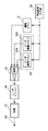
図1は実施例の画像処理装置の構成例を示すブロック図である。
[Device configuration]
FIG. 1 is a block diagram illustrating a configuration example of an image processing apparatus according to an embodiment.
スキャナ11と、電子写真方式のプリンタ12を有する複合機(MFP)10は、内蔵するコントローラ13によって、その機能が制御される。
The functions of a multifunction peripheral (MFP) 10 having a
コントローラ13のCPU17は、RAM15をワークメモリとして、ROM14やハードディスクドライブ(HDD)16に格納されたオペレーティングシステム(OS)や各種プログラムを実行する。HDD16は、制御プログラム、画像処理プログラムなどのプログラムや画像データを記憶する。
The
CPU17は、表示部18にユーザインタフェイスを表示して、表示部18のソフトウェアキーや、操作パネル19のキーボードからユーザの指示を入力する。例えば、ユーザ指示がコピーを示す場合、スキャナ11によって読み取った原稿画像をプリンタ12によって印刷する(コピー機能)。
The
通信部20は、図には示さないが、公衆回線やネットワークに接続する通信インタフェイスである。CPU17は、ユーザ指示がファクシミリ送信を示す場合、スキャナ11によって読み取った原稿画像を、通信部20を制御してユーザが指定する相手先にファクシミリ送信する(ファクシミリ機能)。また、ユーザ指示がプッシュスキャンを示す場合、スキャナ11によって読み取った原稿画像を、通信部20を制御して指定のサーバ装置に送信する(プッシュスキャン機能)。また、通信部20がファクシミリ画像を受信した場合、CPU17は、受信画像をプリンタ12で印刷する(ファクシミリ機能)。また、通信部20が印刷ジョブを受信した場合、CPU17は、印刷ジョブに従いプリンタ12で画像を印刷する(プリンタ機能)。また、通信部20がプルスキャンジョブを受信した場合、CPU17は、スキャンジョブに従いスキャナ11によって読み取った原稿画像を指定のサーバ装置やクライアント装置に送信する(プルスキャン機能)。
Although not shown in the drawing, the
●光学系の構成
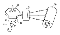
図2はプリンタ12の光学系の構成例を示す図である。
FIG. 2 is a diagram showing a configuration example of the optical system of the
半導体レーザ素子などのビーム光源27から出力された光ビーム26は、球面系あるいはアナモフィック光学系によるコリメータレンズ28を介して回転多面鏡25の反射面に入射する。回転多面鏡25の回転により偏向された光ビーム26は、f-θレンズなどの結像レンズ29を介して、回転する感光ドラム30上に結像し、感光ドラム30上を光走査する。
A
●ドットジェネレータ
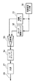
図3はハイブリッドハーフトーンスクリーン(以下、HHS)を生成するドットジェネレータの構成例を示すブロック図である。なお、ドットジェネレータは、コントローラ13の一部として構成される。
Dot Generator FIG. 3 is a block diagram showing a configuration example of a dot generator that generates a hybrid halftone screen (hereinafter, HHS). The dot generator is configured as a part of the
同期信号入力部35は、同期信号として、プリンタ12から1ラインの走査タイミングを示す水平同期信号Hsync、一頁の走査タイミングを示す垂直同期信号Vsync、および、画素クロックVclockを入力する。これら同期信号は、順次、RAM15に割り当てられた画像メモリ31に入力され、感光ドラム30の走査位置に対応する画像データが出力される。また、同期信号は、順次、ROM14またはRAM15に割り当てられたディザ閾値メモリ32に入力され、感光ドラム30の走査位置に対応する、後述する閾値マトリクスが出力される。
The synchronization
比較器33は、感光ドラム30の走査位置に対応する画像データと閾値マトリクスを入力して、画像データと閾値マトリクスの各セルの閾値を比較して、セルごとに、下式に従い二値信号を出力する。
D ≧ Th0の場合、出力信号=‘1’
D < Th0の場合、出力信号=‘0’ …(1)
ここで、Th0は閾値、
Dは画像データ
The
When D ≥ Th0, output signal = '1'
When D <Th0, output signal = '0' (1)
Where Th0 is a threshold,
D is image data
レーザドライバ34は、比較器33が出力する二値信号に従いビーム光源27を駆動して、ビーム光源27の発光を制御する。つまり、比較器33の出力信号が‘1’の場合はビーム光源27に光ビーム26を出力させ(レーザオン)、‘0’の場合はビーム光源27に光ビーム26を出力させない(レーザオフ)。
The
[HHSの作成]
図4はHHSを作成する処理を説明するフローチャートで、CPU17が実行する処理である。
[Create HHS]
FIG. 4 is a flowchart for explaining processing for creating an HHS, which is executed by the
●「揺らぎ」「回転」操作
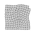
CPU17は、ROM14またはHDD16から、整列した(規則正しく並んだ)正方網点格子列の情報(格子間隔p)を入力する(S21)。図5は正方網点格子列を示す図で、網点格子点が間隔pで整列した格子点列である。HHSの平均格子間隔を与える網点格子の密度は、形成する画像の線数が目標値になるように決定する。
● "Fluctuation" and "Rotation" operations
The
次に、CPU17は、網点格子点列に「揺らぎ」と「回転」操作を与え(S22)、その結果から変位ベクトルを計算する(S23)。図6は「揺らぎ」操作を示す図で、網点格子点Pに、x方向とy方向にランダムな変位Vx、Vy与える操作である。変位ベクトルV1は次式で示される。
V1 = (Vx1, Vy1) …(2)
ここで、Vx1はx方向のランダムな変位、
Vy1はy方向のランダムな変位
Next, the
V1 = (Vx1, Vy1)… (2)
Where Vx1 is a random displacement in the x direction,
Vy1 is a random displacement in the y direction
図7は「揺らぎ」操作によって変位を与えた網点格子点を示す図である。図8は「揺らぎ」操作による各網点格子点の変位ベクトルを示す図で、ランダムな変位を与えるため、変位ベクトル間の相関はない。 FIG. 7 is a diagram showing halftone dot lattice points that are displaced by the “fluctuation” operation. FIG. 8 is a diagram showing a displacement vector of each halftone dot lattice point by the “fluctuation” operation. Since a random displacement is given, there is no correlation between the displacement vectors.
図9は「回転」操作によって点132を回転中心とする変位を与えた網点格子点を示す図である。「回転」操作後の網点格子点の座標は次式で表される。
Px' = (Px - Jx)cosθ - (Py - Jy)sinθ + Jx
Py' = (Px - Jx)sinθ + (Py - Jy)cosθ + Jy …(3)
ここで、(Px, Py)は回転前の網点格子点の座標、
(Px', Py')は回転後の網点格子点の座標、
(Jx, Jy)は回転中心132の座標
FIG. 9 is a diagram showing halftone dot lattice points that are displaced about the
Px '= (Px-Jx) cosθ-(Py-Jy) sinθ + Jx
Py '= (Px-Jx) sinθ + (Py-Jy) cosθ + Jy… (3)
Where (Px, Py) is the coordinates of the halftone dot before rotation,
(Px ', Py') is the coordinates of the halftone dot after rotation,
(Jx, Jy) is the coordinates of the center of
式(3)において、θは回転角で、下式に示すように、回転中心132から離れるに従い小さくなる。
θ = θ0(1 - r/r0) …(4)
ここで、rは回転中心132から網点格子点(Px, Py)までの距離、
r0は回転を与える半径(図9に符号133で示す)、
θ0は回転中心132における回転角
In equation (3), θ is the rotation angle, and decreases as the distance from the
θ = θ 0 (1-r / r 0 )… (4)
Where r is the distance from the
r 0 is a radius to give rotation (indicated by
θ 0 is the rotation angle at the center of
「回転」操作には色々な方法が考えられるが、ここでは簡単な式(4)の方式を説明する。この「回転」操作により、回転前の網点格子点と回転後の網点格子点の変位ベクトルV2は次式で示される。
V2 = (Vx2, Vy2) = (Px'-Px, Py'-Py) …(5)
Although various methods can be considered for the “rotation” operation, a simple method of equation (4) will be described here. By this “rotation” operation, the displacement vector V2 of the halftone dot before rotation and the halftone dot after rotation is expressed by the following equation.
V2 = (Vx2, Vy2) = (Px'-Px, Py'-Py)… (5)
図10は「回転」操作による各網点格子点の変位ベクトルを示す図で、ランダムな変位を与えるため、変位ベクトル間の相関はない。 FIG. 10 is a diagram showing the displacement vector of each halftone dot by the “rotation” operation. Since a random displacement is given, there is no correlation between the displacement vectors.
●ボロノイ分割
次に、CPU17は、変位後の網点格子点を母点としてボロノイ(Voronoi)分割を行いボロノイ多角形を作成し、各ボロノイ多角形の重心点を計算する(S24)。網点格子点Piに対するボロノイ多角形は次式に示す点V(Pi)の集合であり、ボロノイ多角形は網点格子点Piの勢力圏を現す。
V(Pi) = {P|d(P, Pi) < d(P, Pj), ∀j≠i} …(6)
ここで、PjはPiに隣接する網点格子点、
d(P, Pi)は点Pと網点格子点Piの距離、
d(P, Pj)は点Pと網点格子点Pjの距離
Voronoi division Next, the
V (Pi) = (P | d (P, Pi) <d (P, Pj), ∀j ≠ i}… (6)
Where Pj is a halftone dot adjacent to Pi,
d (P, Pi) is the distance between the point P and the halftone dot Pi,
d (P, Pj) is the distance between point P and halftone dot Pj
ボロノイ多角形の辺(ボロノイ境界)は、ドロネ(Delaunay)三角形の外心点を結ぶ線分である。また、ドロネ三角形は、隣接する網点格子点間を結ぶ線分を辺としてもち、網点格子点に対して一義的に決まる。従って、ボロノイ多角形も一義的に決まる。ドロネ三角形の外心点(Gx, Gy)は次式で表される。
Gx = {X02(Y1-Y2) + X12(Y2-Y0) + X22(Y0-Y1) - (Y0-Y1)(Y1-Y2)(Y2-Y0)}/L
Gy = -Gx(X2-X1)/(Y2-Y1) + (X2-X1)(X1+X2)/2/(Y2-Y1) + (Y1+Y2)/2 …(7)
ここで、L = 2{X0(Y1-Y2) + X1(Y2-Y0) + X2(Y0-Y1)}、
(X0, Y0)、(X1, Y1)、(X2, Y2)はドロネ三角形の頂点座標
The sides of the Voronoi polygon (Voronoi boundary) are line segments that connect the outer center points of the Delaunay triangle. The Delaunay triangle has a line segment connecting adjacent halftone lattice points as a side and is uniquely determined with respect to the halftone lattice point. Therefore, the Voronoi polygon is also uniquely determined. The outer center point (Gx, Gy) of the Delaunay triangle is expressed by the following equation.
Gx = {X0 2 (Y1-Y2) + X1 2 (Y2-Y0) + X2 2 (Y0-Y1)-(Y0-Y1) (Y1-Y2) (Y2-Y0)} / L
Gy = -Gx (X2-X1) / (Y2-Y1) + (X2-X1) (X1 + X2) / 2 / (Y2-Y1) + (Y1 + Y2) / 2… (7)
Where L = 2 {X0 (Y1-Y2) + X1 (Y2-Y0) + X2 (Y0-Y1)},
(X0, Y0), (X1, Y1), (X2, Y2) are the coordinates of the vertex of the Delaunay triangle
このように、一つの網点格子点を内部にもつボロノイ多角形を形成し、ボロノイ多角形を網点形状にする。初期の正方網点格子列は周期性をもつが、「揺らぎ」「回転」操作によって周期性は乱される。従って、モアレの発生を抑制することができる。 In this way, a Voronoi polygon having one halftone lattice point is formed, and the Voronoi polygon is formed into a halftone dot shape. The initial square dot grid array has periodicity, but the periodicity is disturbed by “fluctuation” and “rotation” operations. Therefore, the generation of moire can be suppressed.
CPU17は、ボロノイ多角形の重心点を黒化(網点の成長)の中心にする。なお、ボロノイ多角形の重心は、ボロノイ多角形を三角形に分割し、各三角形の重心と面積を求め、各三角形の重心にその三角形の面積を加重して、重心の平均値を計算することで求まる。図11はボロノイ多角形および各ボロノイ多角形の重心(×印)を示す図である。一般に、重心の位置は網点格子点の位置と異なり、重心を新たな黒化の中心とすることで、接近し過ぎた網点格子点を緩和する(引き離す)効果があり、均一性や一様性に効果的である。
The
●多角形の扁平化
次に、CPU17は、黒化領域(網点形状)を決定する(S25)。「揺らぎ」による変位ベクトルV1と、「回転」による変位ベクトルV2は合成されて下式に示すベクトルVが得られる。
V = V1 + V2 = (Vx1+Vx2, Vy1+Vy2) …(8)
Polygon flattening Next, the
V = V1 + V2 = (Vx1 + Vx2, Vy1 + Vy2)… (8)
図12はボロノイ多角形の一つを示す図で、ボロノイ多角形136は重心134と合成変位ベクトル135をもつ。図13は変位ベクトル135に沿ってボロノイ多角形136を扁平化して網点形状を決定する方法を示す図である。
FIG. 12 shows one of the Voronoi polygons. The
ボロノイ多角形136の各頂点と、変位ベクトル135の中点が一致するように各頂点にベクトル135aを配置し、ベクトル135aの始点と終点を頂点とするボロノイ多角形136に相似の多角形136aと136bを生成する。つまり、ベクトル135aに沿ってボロノイ多角形136を各方向に拡張した多角形136aと136bを生成する。そして、多角形136aの頂点A、B、Cおよび多角形136bの頂点D、E、F、Gから、網点形状を示す凸包多角形(扁平化した多角形)ABCDEFGを生成する。この扁平化により、N角形のボロノイ多角形から最大N+2角形の多角形が生成される。
A
●黒化の過程
黒化の過程(網点の成長過程)を図14から図16を参照して説明する。
● Blackening Process The blackening process (halftone dot growth process) will be described with reference to FIGS.
図14はハイライト寄りの網点を示す図で、網点面積率が小さい場合を示す。多角形ABCDEFGは、ボロノイ多角形の重心134を中心として、網点の成長とともに相似形を保持しながら拡大する。つまり、ボロノイ多角形の重心134を網点の成長中心にする。図18は網点面積率30%時の網点を示す図である。変位ベクトルの向きに扁平化された網点が「回転」操作に伴う渦巻状のパターンをもって形成される。
FIG. 14 is a diagram showing halftone dots closer to highlights, and shows a case where the halftone dot area ratio is small. The polygon ABCDEFG expands around the center of
図15は網点が成長して(網点面積率が大きくなり)隣接するボロノイ多角形に接する状態を示す図である。多角形ABCDEFGは、網点面積率が大きくなると、変位ベクトルに沿う向きにある辺BCと辺EFが隣接するボロノイ多角形の辺に接する。辺BCと辺EFは、扁平化前のボロノイ多角形の対応する辺と平行であり、隣接するボロノイ多角形と、点ではなく辺で接する。なお、図15の状態に達すると、変位ベクトルの向きに沿う網点の成長は終了する。 FIG. 15 is a diagram showing a state in which halftone dots grow (the halftone dot area ratio increases) and are in contact with adjacent Voronoi polygons. When the halftone dot area ratio increases, the polygon ABCDEFG is in contact with the side of the Voronoi polygon where the side BC and the side EF in the direction along the displacement vector are adjacent. The side BC and the side EF are parallel to the corresponding side of the Voronoi polygon before flattening, and contact the adjacent Voronoi polygon with a side instead of a point. Note that when the state of FIG. 15 is reached, the growth of halftone dots along the direction of the displacement vector ends.
図16は網点がさらに成長した状態を示す図で、変位ベクトルの向きに交差する方向に網点が成長し、辺ABと辺DEが隣接するボロノイ多角形の辺に接する。この状態で白領域として残るのは、△P1A'G'と△P2C'D'で、扁平化前のボロノイ多角形内の一部に白領域が集中する。 FIG. 16 is a diagram showing a state in which the halftone dot is further grown. The halftone dot grows in a direction intersecting the direction of the displacement vector, and the side AB and the side DE are in contact with the adjacent Voronoi polygon side. In this state, ΔP1A′G ′ and ΔP2C′D ′ remain as white areas, and the white areas are concentrated in a part of the Voronoi polygon before flattening.
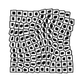
図18から図20は黒化(網点の成長)過程を示す図で、変位ベクトルの向きに沿って網点が成長する様子を示す図である。 FIGS. 18 to 20 are diagrams showing a blackening process (growth of halftone dots) and showing how the halftone dots grow along the direction of the displacement vector.
●閾値マトリクスの作成
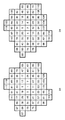
次に、CPU17は、閾値マトリクスを作成する(S26)。図17はあるボロノイ多角形の黒化(網点の成長)用の閾値マトリクスを示す図である。
Creation of threshold matrix Next, the
閾値マトリクスは、ボロノイ多角形内をドットサイズに応じて分割し、各区画(セル)に、ドットをオフからオンに切り替える、画素値に対する閾値を設定したものである。ボロノイ多角形が沢山の画素(区画)を含む場合、成長過程の網点形状は、前述した扁平化後の多角形に略相似である。しかし、解像度が低いプリンタにおいて高線数のHHSを形成すると、一つのボロノイ多角形が含む画素(区画)の数は極めて少なく、成長過程の網点の形状は扁平化後の多角形に相似とは言えず、多少変形するが、白ドット面積の集中化効果に違いはない。 The threshold matrix is obtained by dividing the inside of the Voronoi polygon according to the dot size and setting thresholds for pixel values for switching the dots from off to on in each section (cell). When the Voronoi polygon includes many pixels (sections), the halftone dot shape in the growth process is substantially similar to the flattened polygon described above. However, when HHS with a high line number is formed in a printer with low resolution, one Voronoi polygon contains very few pixels (partitions), and the halftone dot shape in the growth process is similar to the polygon after flattening. However, there is no difference in the concentration effect of the white dot area.
勿論、CPU17は、一つの網点格子点に対応するボロノイ多角形の閾値マトリクスを作成するわけではなく、HHS全体のボロノイ多角形の閾値マトリクスを作成する。これら閾値マトリクスは、変位前の網点格子点の位置に関連付けされて、例えばHDD16に格納される。
Of course, the
[階調数の増加]
図17に示す閾値マトリクスの例では、画素の数が60個のため61階調しか表現できない。そこで、レーザドライバ34による光ビームのパルス幅変調を加えて、階調数を増すことが可能である。
[Increase the number of gradations]
In the example of the threshold matrix shown in FIG. 17, since the number of pixels is 60, only 61 gradations can be expressed. Therefore, the number of gradations can be increased by applying pulse width modulation of the light beam by the
図21は印刷画像の階調数を増やす場合のドットジェネレータの構成例を示すブロック図である。図3と異なる構成は、ディザ閾値メモリ32aと32bの二つのディザ閾値メモリがある点である。図22はディザ閾値メモリ32aと32bに格納された閾値マトリクスを示す図で、図22(a)は奇数の閾値を、図22(b)は偶数の閾値を示すように交互に閾値が設定されている。つまり、あるボロノイ多角形について、ディザ閾値メモリ32aには図22(a)に示す閾値マトリクスが格納され、ディザ閾値メモリ32bには図22(b)に示す閾値マトリクスが格納される。
FIG. 21 is a block diagram illustrating a configuration example of a dot generator when the number of gradations of a print image is increased. A configuration different from FIG. 3 is that there are two
比較器33は、感光ドラム30の走査位置に対応する画像データと二つの閾値マトリクスを入力して、画像データと各セルの閾値を比較して、セルごとに、下式に従い三値信号を出力する。
Th0 ≦ D の場合、出力信号=‘2’
Th1 ≦ D < Th0の場合、出力信号=‘1’ …(9)
D < Th1の場合、出力信号=‘0’
ここで、Th0、Th1は閾値、
Dは画像データ
Output signal = '2' when Th0 ≤ D
When Th1 ≤ D <Th0, output signal = '1' (9)
When D <Th1, output signal = '0'
Where Th0 and Th1 are thresholds,
D is image data
なお、図22に示す例では、入力される画像データを120で正規化する必要がある。つまり、画像データが8ビットだとすると、比較器33は、画像データ×120/255を計算し、正規化後の画像データによって上記の比較を行う。なお、図22に示す例では、正規化後の画像データは小数点以下一桁の有効数字をもつことが好ましい。
In the example shown in FIG. 22, the input image data needs to be normalized by 120. That is, assuming that the image data is 8 bits, the
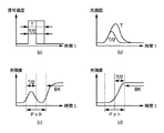
レーザドライバ34は、比較器33が出力する三値信号に従いビーム光源27の発光を制御する。つまり、図23(a)に示すように、比較器33の出力信号が‘2’の場合はビーム光源27にパルス幅Tの光ビーム26を出力させる。また、‘1’の場合はビーム光源27にパルス幅T/2の光ビーム26を出力させ、‘0’の場合はビーム光源27に光ビーム26を出力させない。こうすれば、パルス幅変調により階調数が増え、画素の数が60の閾値マトリクスを用いた場合、121階調を得ることができる。
The
ただし、図23(b)に示すようにパルス幅T/2の光強度のピーク値は、パルス幅Tの光強度のピーク値に比べて低く、パルス幅T/2による露光は非常に不安定である。そこで、レーザドライバ34は、パルス幅T/2で形成するドット(以下、半ドット)が、パルス幅Tで形成したまたは形成するドット(以下、全ドット)に隣接するようにビーム光源27の発光タイミングを制御する。
However, as shown in FIG. 23 (b), the peak value of the light intensity with the pulse width T / 2 is lower than the peak value of the light intensity with the pulse width T, and the exposure with the pulse width T / 2 is very unstable. It is. Therefore, the
例えば、図23(c)はドット幅の左側に半ドットを形成し、続いて全ドットを形成するようにビーム光源27の発光タイミングを制御する例であるが、ドット幅の右側に全ドットから孤立した半ドットが形成されるため、半ドットは非常に不安定である。一方、図23(d)はドット幅の右側に半ドットを形成し、続いて全ドットを形成するようにビーム光源27の発光タイミングを制御する例であるが、全ドットに隣接して半ドットが形成されるため、安定して半ドットを形成することができる。
For example, FIG. 23 (c) is an example in which the light emission timing of the
上記ではプリンタ10のコントローラ13がHHSを生成するように説明した。しかし、形成する画像の線数に応じた平均格子間隔のHHSを予め作成して、HDD16などに格納しておき、画像形成に必要なHHSをディザ閾値メモリ32にロードして利用すればよい。
In the above description, the
このように、電子写真方式のオフィスプリンタにも適用可能なハイブリッドハーフトーンスクリーン(HHS)を生成することができる。このHHSを使用して印刷画像を形成すれば、白領域のクラスタ化により高濃度域(シャドウ域)における階調性の安定性を図ることができる。従って、電子写真方式のオフィスプリンタにおいて、白ドットを導入せずに、モアレを抑制した、高線数で高画質な安定した階調再現性が達成される。 In this manner, a hybrid halftone screen (HHS) that can be applied to an electrophotographic office printer can be generated. If a print image is formed using this HHS, the gradation of the high density region (shadow region) can be stabilized by clustering the white region. Therefore, in an electrophotographic office printer, stable gradation reproducibility with a high number of lines and high image quality can be achieved without introducing white dots and suppressing moire.
以下、本発明にかかる実施例2の画像処理を説明する。なお、実施例2において、実施例1と略同様の構成については、同一符号を付して、その詳細説明を省略する。 The image processing according to the second embodiment of the present invention will be described below. Note that the same reference numerals in the second embodiment denote the same parts as in the first embodiment, and a detailed description thereof will be omitted.
図24は実施例2のHHSを生成する処理を説明するフローチャートで、CPU17が実行する処理である。図4に示す処理と異なるのは、格子点列に副走査方向の変位与える(S27)ことである。
FIG. 24 is a flowchart for explaining processing for generating an HHS according to the second embodiment. This processing is executed by the
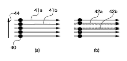
前述したように、電子写真方式の印刷装置は、ピッチむらやバンディングノイズの影響を受け易い。図25(a)に示すように、レーザスポット40は、感光ドラム30上を主走査され、走査ライン41aと41bは、通常、副走査方向44に規則正しい間隔をもつ。しかし、回転多面鏡26の反射面の傾きや感光ドラム30の回転むらなどにより、図25(b)に破線で示すように、間隔が不規則な走査ライン42aと42bになる。走査ラインの間隔が不規則になると、印刷画像には、帯状の縞模様(所謂バンディングノイズ)が生じて、画質が著しく低下する。
As described above, an electrophotographic printing apparatus is susceptible to pitch unevenness and banding noise. As shown in FIG. 25 (a), the
走査ラインの間隔が不規則に起因する画質劣化を軽減するために、格子点列に副走査方向の変位を与える。副走査方向44を向く変位ベクトルV3は下式で表される。ただし、y方向を副走査方向と定義すると変位ベクトルV3はx方向の成分だけになる。
V3 = (Vx3, Vy3) = (Vx3, 0) …(10)
In order to reduce image quality deterioration caused by irregular scan line intervals, a displacement in the sub-scanning direction is given to the grid of dot points. A displacement vector V3 facing the
V3 = (Vx3, Vy3) = (Vx3, 0)… (10)
前述した変位ベクトルV1、V2に、変位ベクトルV3を合成した、変位ベクトルVは下式で表される。
V = V1 + V2 +α・V3 = (Vx1+Vx2+α・Vx3, Vy1+Vy2) …(11)
ここで、係数αは副走査方向の変位ベクトルの強度を表す
The displacement vector V obtained by combining the displacement vectors V1 and V2 with the displacement vector V3 is expressed by the following equation.
V = V1 + V2 + α ・ V3 = (Vx1 + Vx2 + α ・ Vx3, Vy1 + Vy2)… (11)
Here, the coefficient α represents the intensity of the displacement vector in the sub-scanning direction.
式(11)に示す係数αの大きさを調整して、網点の副走査の連結の強度を制御することができる。 By adjusting the magnitude of the coefficient α shown in the equation (11), it is possible to control the strength of the sub-scanning connection of halftone dots.
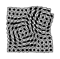
図26は副走査方向の変位を加えた各格子点の変位ベクトルを示す図で、図10に示す変位ベクトルに比べて副走査方向(図26においては縦方向)のベクトル成分が増えている。図27は網点面積率30%時の網点を示す図で、図18に示す網点と比べると、網点が副走査方向に扁平化されている。また、図28は網点面積率70%の網点を示す図で、前述した係数αの設定に依存するが、網点は全体的に副走査方向に連結して行くことが分かる。 FIG. 26 is a diagram showing a displacement vector of each lattice point to which displacement in the sub-scanning direction is added, and the vector component in the sub-scanning direction (vertical direction in FIG. 26) is increased as compared with the displacement vector shown in FIG. FIG. 27 is a diagram showing halftone dots when the halftone dot area ratio is 30%. Compared with the halftone dots shown in FIG. 18, the halftone dots are flattened in the sub-scanning direction. FIG. 28 is a diagram showing halftone dots with a halftone dot area ratio of 70%, and it is understood that the halftone dots are connected in the sub-scanning direction as a whole, depending on the setting of the coefficient α described above.
図29は網点の副走査方向の連結による効果を説明する図である。 FIG. 29 is a diagram for explaining the effect of connecting halftone dots in the sub-scanning direction.
通常、光ビームのスポット40は、副走査方向44に長軸をもつ楕円である。走査ライン42aと42bにピッチむらが生じても、副走査方向44に連続する線はスポット40が重なるため、ピッチむらの影響を受け難い。一方、主走査方向に連続する線は、スポット40が重なる効果を受け難く、バンディングノイズを解消することができない。例えば、ピッチむらがあるプリンタによって二画素おきに一画素幅の縦線(副走査方向に沿う線)と横線(主走査方向に沿う線)を等間隔に描画する。この場合、縦線はピッチむらの影響を受けないが、横線はピッチむらの影響を受け、横線の間隔が変化し、これが濃度むらとなってバンディングノイズを生じる。
Usually, the
実施例2のように、網点格子点に副走査方向の変位を与えれば、副走査方向に連結したライン成分を多く含むようになり、ピッチむらの影響を受け難くなり、安定した高画質出力を期待することができる。 If the displacement in the sub-scanning direction is given to the halftone dot as in the second embodiment, it will contain many line components connected in the sub-scanning direction, making it less susceptible to pitch unevenness and stable high-quality output. Can be expected.
[他の実施例]
なお、本発明は、複数の機器(例えばコンピュータ、インタフェイス機器、リーダ、プリンタなど)から構成されるシステムに適用しても、一つの機器からなる装置(例えば、複写機、ファクシミリ装置、制御装置など)に適用してもよい。
[Other embodiments]
Note that the present invention can be applied to a system composed of a plurality of devices (for example, a computer, an interface device, a reader, a printer, etc.), or a device (for example, a copier, a facsimile machine, a control device) composed of a single device. Etc.).
また、本発明の目的は、上記実施例の機能を実現するコンピュータプログラムを記録した記憶媒体をシステムまたは装置に供給し、そのシステムまたは装置のコンピュータ(CPUやMPU)が前記コンピュータプログラムを実行することでも達成される。この場合、記憶媒体から読み出されたソフトウェア自体が上記実施例の機能を実現することになり、そのコンピュータプログラムと、そのコンピュータプログラムを記憶する、コンピュータが読み取り可能な記憶媒体は本発明を構成する。 Another object of the present invention is to supply a storage medium storing a computer program for realizing the functions of the above-described embodiments to a system or apparatus, and the computer (CPU or MPU) of the system or apparatus executes the computer program. But it is achieved. In this case, the software read from the storage medium itself realizes the functions of the above embodiments, and the computer program and the computer-readable storage medium storing the computer program constitute the present invention. .
また、前記コンピュータプログラムの実行により上記機能が実現されるだけではない。つまり、そのコンピュータプログラムの指示により、コンピュータ上で稼働するオペレーティングシステム(OS)および/または第一の、第二の、第三の、…プログラムなどが実際の処理の一部または全部を行い、それによって上記機能が実現される場合も含む。 Further, the above functions are not only realized by the execution of the computer program. That is, according to the instruction of the computer program, the operating system (OS) and / or the first, second, third,... This includes the case where the above function is realized.
また、前記コンピュータプログラムがコンピュータに接続された機能拡張カードやユニットなどのデバイスのメモリに書き込まれていてもよい。つまり、そのコンピュータプログラムの指示により、第一の、第二の、第三の、…デバイスのCPUなどが実際の処理の一部または全部を行い、それによって上記機能が実現される場合も含む。 The computer program may be written in a memory of a device such as a function expansion card or unit connected to the computer. That is, it includes the case where the CPU of the first, second, third,... Device performs part or all of the actual processing according to the instructions of the computer program, thereby realizing the above functions.
本発明を前記記憶媒体に適用する場合、その記憶媒体には、先に説明したフローチャートに対応または関連するコンピュータプログラムが格納される。 When the present invention is applied to the storage medium, the storage medium stores a computer program corresponding to or related to the flowchart described above.
Claims (12)
所定領域に配置された網点格子点の座標を非周期的かつランダムに変位する変位手段と、
前記所定領域を前記変位した網点格子点を囲む多角形に分割する分割手段と、
前記多角形が囲む網点を前記変位の向きに成長させる前記閾値マトリクスを生成する生成手段とを有することを特徴とする情報処理装置。 An information processing apparatus for generating a threshold matrix for halftone processing,
A displacement means for aperiodically and randomly displacing the coordinates of the halftone dot arranged in the predetermined area;
Dividing means for dividing the predetermined region into polygons surrounding the displaced halftone dot lattice points;
An information processing apparatus comprising: a generation unit configured to generate the threshold value matrix that grows halftone dots surrounded by the polygon in the displacement direction.
画像形成装置の同期信号に従い、画像データを入力し、前記閾値マトリクスを前記メモリから入力して、前記画像データと前記閾値マトリクスの各セルの閾値を比較する比較手段と、
前記比較の結果に応じて、前記画像形成装置のレーザ光源を駆動する駆動手段とを有することを特徴とする画像処理装置。 A memory for storing a threshold value matrix generated by the information processing device according to any one of claims 1 to 8 ,
Comparing means for inputting image data in accordance with a synchronization signal of the image forming apparatus, inputting the threshold value matrix from the memory, and comparing the threshold value of each cell of the image data and the threshold value matrix;
Depending on the result of the comparison, the image processing apparatus according to claim Rukoto to have a driving means for driving the laser light source of the image forming apparatus.
前記変位手段が、所定領域に配置された網点格子点の座標を非周期的かつランダムに変位し、
前記分割手段が、前記所定領域を前記変位した網点格子点を囲む多角形に分割し、
前記生成手段が、前記多角形が囲む網点を前記変位の向きに成長させる前記閾値マトリクスを生成することを特徴とする情報処理方法。 An information processing method for an information processing apparatus that includes a displacement unit, a division unit, and a generation unit, and generates a threshold matrix for halftone processing,
The displacement means displaces coordinates of halftone lattice points arranged in a predetermined region aperiodically and randomly ,
The dividing means divides the predetermined area into polygons surrounding the displaced halftone dot lattice points,
The information processing method characterized in that the generation means generates the threshold matrix for growing halftone dots surrounded by the polygon in the direction of the displacement.
前記比較手段が、画像形成装置の同期信号に従い、画像データを入力し、前記閾値マトリクスを前記メモリから入力して、前記画像データと前記閾値マトリクスの各セルの閾値を比較し、The comparison unit inputs image data in accordance with a synchronization signal of the image forming apparatus, inputs the threshold matrix from the memory, compares the threshold of each cell of the image data and the threshold matrix,
前記駆動手段が、前記比較の結果に応じて、前記画像形成装置のレーザ光源を駆動することを特徴とする画像処理方法。An image processing method, wherein the driving unit drives a laser light source of the image forming apparatus according to a result of the comparison.
Priority Applications (4)
| Application Number | Priority Date | Filing Date | Title |
|---|---|---|---|
| JP2007269529A JP4909232B2 (en) | 2007-10-16 | 2007-10-16 | Information processing apparatus, image processing apparatus, and methods thereof |
| US12/246,977 US8149463B2 (en) | 2007-10-16 | 2008-10-07 | Information processing apparatus, image processing apparatus and method thereof, which create and use a halftone screen |
| EP08166581.2A EP2051498B1 (en) | 2007-10-16 | 2008-10-14 | Information processing apparatus, image processing apparatus and method thereof |
| CN2008101703545A CN101415062B (en) | 2007-10-16 | 2008-10-16 | Information processing apparatus, image processing apparatus and method thereof |
Applications Claiming Priority (1)
| Application Number | Priority Date | Filing Date | Title |
|---|---|---|---|
| JP2007269529A JP4909232B2 (en) | 2007-10-16 | 2007-10-16 | Information processing apparatus, image processing apparatus, and methods thereof |
Publications (3)
| Publication Number | Publication Date |
|---|---|
| JP2009100229A JP2009100229A (en) | 2009-05-07 |
| JP2009100229A5 JP2009100229A5 (en) | 2010-12-02 |
| JP4909232B2 true JP4909232B2 (en) | 2012-04-04 |
Family
ID=40293785
Family Applications (1)
| Application Number | Title | Priority Date | Filing Date |
|---|---|---|---|
| JP2007269529A Expired - Fee Related JP4909232B2 (en) | 2007-10-16 | 2007-10-16 | Information processing apparatus, image processing apparatus, and methods thereof |
Country Status (4)
| Country | Link |
|---|---|
| US (1) | US8149463B2 (en) |
| EP (1) | EP2051498B1 (en) |
| JP (1) | JP4909232B2 (en) |
| CN (1) | CN101415062B (en) |
Families Citing this family (17)
| Publication number | Priority date | Publication date | Assignee | Title |
|---|---|---|---|---|
| JP4753191B2 (en) * | 2008-05-15 | 2011-08-24 | 一夫 相坂 | Image recognition method |
| US8520277B2 (en) * | 2010-08-03 | 2013-08-27 | Canon Kabushiki Kaisha | Image processing apparatus, image processing method, and storage medium |
| JP2012248997A (en) * | 2011-05-26 | 2012-12-13 | Oki Data Corp | Screen image generation method and image forming device |
| JP5644808B2 (en) * | 2012-04-27 | 2014-12-24 | コニカミノルタ株式会社 | Image processing apparatus and image processing method |
| JP6099952B2 (en) | 2012-11-29 | 2017-03-22 | キヤノン株式会社 | Gamma correction table creation method, or image processing method using gamma correction table and control method thereof |
| CN103152509B (en) * | 2013-04-02 | 2015-04-01 | 武汉大学 | Image halftone threshold value matrix design method based on nonlinear characteristic of printer |
| CN105593765B (en) * | 2013-09-27 | 2018-04-03 | 佳能株式会社 | Conductive member for electrophotography, handle box and electronic photographing device |
| JP6192466B2 (en) * | 2013-09-27 | 2017-09-06 | キヤノン株式会社 | Electrophotographic conductive member, process cartridge, and electrophotographic apparatus |
| CN105579913B (en) * | 2013-09-27 | 2018-02-16 | 佳能株式会社 | Conductive member for electrophotography, handle box and electronic photographing device |
| GB2522422A (en) * | 2014-01-22 | 2015-07-29 | Landa Corp Ltd | Apparatus and method for half-toning |
| JP6351342B2 (en) * | 2014-04-04 | 2018-07-04 | キヤノン株式会社 | Method for creating dot arrangement or threshold matrix, image processing apparatus, and storage medium |
| CN103985320A (en) * | 2014-05-27 | 2014-08-13 | 利亚德光电股份有限公司 | Method for restraining moire and display device capable of restraining moire |
| JP6441046B2 (en) * | 2014-11-26 | 2018-12-19 | 三菱製紙株式会社 | Light transmissive conductive material |
| CN104537654B (en) * | 2014-12-19 | 2017-04-12 | 大连理工大学 | Printed image tampering forensic methods based on half-tone dot location distortion |
| US10410100B1 (en) | 2017-11-14 | 2019-09-10 | Landa Corporation Ltd. | AM Screening |
| CN111324470B (en) * | 2020-01-20 | 2023-11-07 | 北京百度网讯科技有限公司 | Method and device for generating information |
| CN111724322B (en) * | 2020-06-19 | 2023-08-22 | 杭州海康机器人股份有限公司 | Method and system for removing noise of laser stripe image |
Family Cites Families (8)
| Publication number | Priority date | Publication date | Assignee | Title |
|---|---|---|---|---|
| US6128099A (en) * | 1995-06-08 | 2000-10-03 | Delabastita; Paul A. | Halftone screen generator, halftone screen and method for generating same |
| US6249355B1 (en) * | 1998-10-26 | 2001-06-19 | Hewlett-Packard Company | System providing hybrid halftone |
| US20040223189A1 (en) * | 2003-05-09 | 2004-11-11 | Anoop Bhattacharjya | Rapid design of smooth multi-level multi-frequency screens |
| JP2005136612A (en) * | 2003-10-29 | 2005-05-26 | Dainippon Screen Mfg Co Ltd | Halftone dot formation method, halftone dot formation apparatus and halftone dot recording medium |
| JP4514132B2 (en) * | 2004-05-28 | 2010-07-28 | 大日本スクリーン製造株式会社 | Threshold matrix generation method for halftone image generation, halftone image generation method and apparatus, and threshold matrix |
| JP4111451B2 (en) * | 2004-10-08 | 2008-07-02 | 大日本スクリーン製造株式会社 | Threshold matrix generation method and recording medium |
| JP5194356B2 (en) * | 2005-12-01 | 2013-05-08 | 大日本印刷株式会社 | Gravure printing method and printed matter |
| JP4707636B2 (en) | 2006-09-26 | 2011-06-22 | 大日本スクリーン製造株式会社 | Image recording method and image recording apparatus |
-
2007
- 2007-10-16 JP JP2007269529A patent/JP4909232B2/en not_active Expired - Fee Related
-
2008
- 2008-10-07 US US12/246,977 patent/US8149463B2/en not_active Expired - Fee Related
- 2008-10-14 EP EP08166581.2A patent/EP2051498B1/en not_active Not-in-force
- 2008-10-16 CN CN2008101703545A patent/CN101415062B/en not_active Expired - Fee Related
Also Published As
| Publication number | Publication date |
|---|---|
| EP2051498B1 (en) | 2013-04-10 |
| US8149463B2 (en) | 2012-04-03 |
| CN101415062A (en) | 2009-04-22 |
| US20090097073A1 (en) | 2009-04-16 |
| EP2051498A3 (en) | 2010-01-20 |
| CN101415062B (en) | 2012-07-25 |
| EP2051498A2 (en) | 2009-04-22 |
| JP2009100229A (en) | 2009-05-07 |
Similar Documents
| Publication | Publication Date | Title |
|---|---|---|
| JP4909232B2 (en) | Information processing apparatus, image processing apparatus, and methods thereof | |
| JP4929122B2 (en) | Image processing apparatus and method, and program | |
| JP6639247B2 (en) | Image processing apparatus, image processing method, and program | |
| EP2544443B1 (en) | Threshold matrix generation device and method for generating threshold matrix for generating threshold matrix of predetermined size used for halftone processing of multitone image data using dithering method | |
| JP2007156394A (en) | Image forming apparatus and image forming method | |
| JP2009253472A (en) | Image processing apparatus, and method thereof | |
| JP6541215B2 (en) | Image processing apparatus and method | |
| JP2009100230A (en) | Image processing apparatus and method thereof | |
| JP4881274B2 (en) | Image processing apparatus and method | |
| JP2000228728A (en) | Image processing method for color electronic photograph and its electronic photographing system | |
| JP5264412B2 (en) | Image processing apparatus and image processing method | |
| JP5219591B2 (en) | Image processing apparatus and method | |
| JP2019146037A (en) | Image processing apparatus and method for controlling the same, and program | |
| JP2002118746A (en) | Image forming method | |
| JP2008544605A (en) | Automatic generation of supercell halftoning threshold arrays for high addressability devices | |
| JP5459084B2 (en) | Threshold matrix creation device and threshold matrix creation method | |
| JP2000094756A (en) | Apparatus for processing electrophotographic image and method therefor | |
| JP5149648B2 (en) | Image processing apparatus and method | |
| JP7337237B2 (en) | IMAGE FORMING APPARATUS, CONTROL METHOD THEREOF, AND PROGRAM | |
| JP7339774B2 (en) | IMAGE FORMING APPARATUS, CONTROL METHOD THEREOF, AND PROGRAM | |
| JP7116638B2 (en) | IMAGE FORMING APPARATUS, CONTROL METHOD THEREOF, AND PROGRAM | |
| JP2019016887A (en) | Image processing apparatus, program, and image processing method | |
| JP4020115B2 (en) | Electrophotographic image processing apparatus and method | |
| JP4569345B2 (en) | Image forming apparatus and image forming method | |
| JP2008288846A (en) | Image processor and image processing method |
Legal Events
| Date | Code | Title | Description |
|---|---|---|---|
| A521 | Written amendment |
Free format text: JAPANESE INTERMEDIATE CODE: A523 Effective date: 20101018 |
|
| A621 | Written request for application examination |
Free format text: JAPANESE INTERMEDIATE CODE: A621 Effective date: 20101018 |
|
| A977 | Report on retrieval |
Free format text: JAPANESE INTERMEDIATE CODE: A971007 Effective date: 20111027 |
|
| A131 | Notification of reasons for refusal |
Free format text: JAPANESE INTERMEDIATE CODE: A131 Effective date: 20111104 |
|
| A521 | Written amendment |
Free format text: JAPANESE INTERMEDIATE CODE: A523 Effective date: 20111128 |
|
| TRDD | Decision of grant or rejection written | ||
| A01 | Written decision to grant a patent or to grant a registration (utility model) |
Free format text: JAPANESE INTERMEDIATE CODE: A01 Effective date: 20111216 |
|
| A01 | Written decision to grant a patent or to grant a registration (utility model) |
Free format text: JAPANESE INTERMEDIATE CODE: A01 |
|
| A61 | First payment of annual fees (during grant procedure) |
Free format text: JAPANESE INTERMEDIATE CODE: A61 Effective date: 20120113 |
|
| FPAY | Renewal fee payment (event date is renewal date of database) |
Free format text: PAYMENT UNTIL: 20150120 Year of fee payment: 3 |
|
| R151 | Written notification of patent or utility model registration |
Ref document number: 4909232 Country of ref document: JP Free format text: JAPANESE INTERMEDIATE CODE: R151 |
|
| FPAY | Renewal fee payment (event date is renewal date of database) |
Free format text: PAYMENT UNTIL: 20150120 Year of fee payment: 3 |
|
| LAPS | Cancellation because of no payment of annual fees |