JP6099952B2 - Gamma correction table creation method, or image processing method using gamma correction table and control method thereof - Google Patents
Gamma correction table creation method, or image processing method using gamma correction table and control method thereof Download PDFInfo
- Publication number
- JP6099952B2 JP6099952B2 JP2012261311A JP2012261311A JP6099952B2 JP 6099952 B2 JP6099952 B2 JP 6099952B2 JP 2012261311 A JP2012261311 A JP 2012261311A JP 2012261311 A JP2012261311 A JP 2012261311A JP 6099952 B2 JP6099952 B2 JP 6099952B2
- Authority
- JP
- Japan
- Prior art keywords
- gamma correction
- density
- correction table
- unit
- patch
- Prior art date
- Legal status (The legal status is an assumption and is not a legal conclusion. Google has not performed a legal analysis and makes no representation as to the accuracy of the status listed.)
- Active
Links
- 238000012937 correction Methods 0.000 title claims description 230
- 238000000034 method Methods 0.000 title claims description 55
- 238000003672 processing method Methods 0.000 title description 2
- 238000012545 processing Methods 0.000 claims description 118
- 238000005259 measurement Methods 0.000 claims description 65
- 238000004590 computer program Methods 0.000 claims description 3
- 239000011159 matrix material Substances 0.000 claims description 2
- 238000001514 detection method Methods 0.000 description 26
- 230000009467 reduction Effects 0.000 description 21
- 238000010586 diagram Methods 0.000 description 20
- 238000012935 Averaging Methods 0.000 description 4
- 230000000740 bleeding effect Effects 0.000 description 3
- 238000011946 reduction process Methods 0.000 description 3
- 238000006243 chemical reaction Methods 0.000 description 2
- 238000007796 conventional method Methods 0.000 description 2
- 230000000694 effects Effects 0.000 description 2
- 230000006870 function Effects 0.000 description 2
- 241000533901 Narcissus papyraceus Species 0.000 description 1
- 230000015572 biosynthetic process Effects 0.000 description 1
- 238000001739 density measurement Methods 0.000 description 1
- 230000006866 deterioration Effects 0.000 description 1
- 239000006185 dispersion Substances 0.000 description 1
- 238000006073 displacement reaction Methods 0.000 description 1
- 230000001771 impaired effect Effects 0.000 description 1
- 239000000203 mixture Substances 0.000 description 1
- 238000001454 recorded image Methods 0.000 description 1
- 238000004904 shortening Methods 0.000 description 1
- 230000001131 transforming effect Effects 0.000 description 1
Images


Classifications
-
- G—PHYSICS
- G06—COMPUTING; CALCULATING OR COUNTING
- G06K—GRAPHICAL DATA READING; PRESENTATION OF DATA; RECORD CARRIERS; HANDLING RECORD CARRIERS
- G06K15/00—Arrangements for producing a permanent visual presentation of the output data, e.g. computer output printers
- G06K15/02—Arrangements for producing a permanent visual presentation of the output data, e.g. computer output printers using printers
- G06K15/18—Conditioning data for presenting it to the physical printing elements
- G06K15/1867—Post-processing of the composed and rasterized print image
- G06K15/1872—Image enhancement
- G06K15/1881—Halftoning
-
- H—ELECTRICITY
- H04—ELECTRIC COMMUNICATION TECHNIQUE
- H04N—PICTORIAL COMMUNICATION, e.g. TELEVISION
- H04N1/00—Scanning, transmission or reproduction of documents or the like, e.g. facsimile transmission; Details thereof
- H04N1/40—Picture signal circuits
- H04N1/405—Halftoning, i.e. converting the picture signal of a continuous-tone original into a corresponding signal showing only two levels
-
- B—PERFORMING OPERATIONS; TRANSPORTING
- B41—PRINTING; LINING MACHINES; TYPEWRITERS; STAMPS
- B41J—TYPEWRITERS; SELECTIVE PRINTING MECHANISMS, i.e. MECHANISMS PRINTING OTHERWISE THAN FROM A FORME; CORRECTION OF TYPOGRAPHICAL ERRORS
- B41J2/00—Typewriters or selective printing mechanisms characterised by the printing or marking process for which they are designed
- B41J2/005—Typewriters or selective printing mechanisms characterised by the printing or marking process for which they are designed characterised by bringing liquid or particles selectively into contact with a printing material
- B41J2/01—Ink jet
- B41J2/21—Ink jet for multi-colour printing
-
- G—PHYSICS
- G03—PHOTOGRAPHY; CINEMATOGRAPHY; ANALOGOUS TECHNIQUES USING WAVES OTHER THAN OPTICAL WAVES; ELECTROGRAPHY; HOLOGRAPHY
- G03G—ELECTROGRAPHY; ELECTROPHOTOGRAPHY; MAGNETOGRAPHY
- G03G15/00—Apparatus for electrographic processes using a charge pattern
- G03G15/01—Apparatus for electrographic processes using a charge pattern for producing multicoloured copies
-
- H—ELECTRICITY
- H04—ELECTRIC COMMUNICATION TECHNIQUE
- H04N—PICTORIAL COMMUNICATION, e.g. TELEVISION
- H04N1/00—Scanning, transmission or reproduction of documents or the like, e.g. facsimile transmission; Details thereof
- H04N1/40—Picture signal circuits
- H04N1/407—Control or modification of tonal gradation or of extreme levels, e.g. background level
- H04N1/4076—Control or modification of tonal gradation or of extreme levels, e.g. background level dependent on references outside the picture
- H04N1/4078—Control or modification of tonal gradation or of extreme levels, e.g. background level dependent on references outside the picture using gradational references, e.g. grey-scale test pattern analysis
Description
本発明は、デジタル画像データに基づいて記録媒体上に画像を形成するためのガンマ補正テーブルを作成する方法、あるいはガンマ補正テーブルを用いた画像処理方法に関する。 The present invention relates to a method for creating a gamma correction table for forming an image on a recording medium based on digital image data, or an image processing method using the gamma correction table.
デジタル画像データに基づいて記録媒体上に画像を形成する画像形成装置は、画像形成装置によって出力濃度特性が異なる。そのため、同じデジタル画像データに基づいて記録媒体上に画像を形成しても、記録媒体上に出力された濃度がそれぞれ異なるということが起こる。そこで画像形成装置では一般に、所望のデジタル画像データを記録媒体上に出力できるように、各画像形成装置の特性に合わせてデジタル画像データを補正する。これはガンマ補正として知られている。 An image forming apparatus that forms an image on a recording medium based on digital image data has different output density characteristics depending on the image forming apparatus. For this reason, even when an image is formed on a recording medium based on the same digital image data, the density output on the recording medium may differ. Therefore, in general, an image forming apparatus corrects digital image data in accordance with the characteristics of each image forming apparatus so that desired digital image data can be output onto a recording medium. This is known as gamma correction.
また、パソコン等で扱うデジタル画像データの階調数に比べて、プリンタ等の画像形成装置が出力可能な画素当たりの階調数は少ない場合が多い。そこで、デジタル画像データを画像形成装置が出力可能な階調数に変換するため、デジタル画像データに対して低階調化処理を施す。低階調化のなかでもスクリーン処理は一般に、入力されたデジタル画像データを、ある一定の面積で疑似的に階調を表現する画像デ―タに変換する。 In many cases, the number of gradations per pixel that can be output by an image forming apparatus such as a printer is smaller than the number of gradations of digital image data handled by a personal computer or the like. Therefore, in order to convert the digital image data into the number of gradations that can be output by the image forming apparatus, a gradation reduction process is performed on the digital image data. Among the gradation reductions, screen processing generally converts input digital image data into image data that expresses pseudo gradations in a certain area.
一方、画像データに対してスクリーン処理をすると、解像性が損なわれてしまう場合がある。特に、文字や線が描かれた画像は、文字や線に途切れが生じ、画質劣化が著しいことが知られている。特許文献1に開示された方法では、画像の輪郭部を検出し、輪郭部に対して強調又は低減処理を行った後にコントーン処理して出力する。輪郭部でない画素に対しては、スクリーン処理結果を出力する。特許文献1では、輪郭部とそれ以外の領域では、異なるガンマ補正を行う。
On the other hand, when screen processing is performed on image data, resolution may be impaired. In particular, it is known that an image in which characters and lines are drawn is discontinuous in characters and lines and image quality is significantly deteriorated. In the method disclosed in
ガンマ補正に用いられるガンマ補正テーブルは、実際に記録媒体上に記録した濃度をセンサにより測定して得られる出力濃度特性に基づいて作成される。 The gamma correction table used for gamma correction is created based on output density characteristics obtained by measuring the density actually recorded on the recording medium with a sensor.
しかしながら従来の方法では、精度よく出力濃度特性を得られないという課題があった。特許文献1に開示された方法において、輪郭部は1画素単独で階調を表している。一方輪郭部以外では、複数画素からなるある領域で擬似的に階調を表している。そこでそれぞれに適したガンマ補正テーブルを作成する必要がある。しかしながら従来の方法では、必ずしも適正なガンマ補正テーブルを作成できなかった。
However, the conventional method has a problem that the output density characteristic cannot be obtained with high accuracy. In the method disclosed in
特許文献1における輪郭部においては、注目画素に対応する出力濃度は、ドットゲインやインクのにじみなどを考慮する必要があり、入力画像データよりも解像度の低いセンサを用いて測定する。ところが、輪郭部を形成する注目画素の周囲には、それぞれの入力階調値に対応すべき出力濃度が混在する可能性が高い。そのため、センサが測定した出力濃度と入力階調値を一対一に対応させることができず、適切な出力濃度特性を得られないため、結果としてガンマ補正テーブルの作成が困難となる。このように、画像形成装置が記録媒体上に記録した出力濃度をセンサが測定した結果に基づいて、出力濃度特性を算出するためには、出力濃度の測定を補正すべき場合がある。
In the contour portion in
そこで本発明は、センサにより記録媒体上の出力濃度を測定した結果を適切に補正し、精度よくガンマ補正テーブルを作成することを目的とする。 Accordingly, an object of the present invention is to appropriately correct the result of measuring the output density on a recording medium by a sensor and to create a gamma correction table with high accuracy.
上述の課題を解決するため、本発明に係るガンマ補正テーブル作成方法は、補正手段とガンマ補正テーブル生成手段とを有する画像形成装置が出力した濃度パッチを測定した結果に基づいて、ガンマ補正テーブルを作成する、前記画像形成装置におけるガンマ補正テーブル作成方法であって、前記補正手段が、複数の縦細線画像を周期的に配置した細線濃度パッチの1つの縦細線画像を単位パターンとし、前記単位パターンにおける細線画素の割合を用いて、前記細線濃度パッチの測定結果である濃度情報を補正することにより、前記縦細線画像を形成する細線画素あたりの出力濃度を求める補正工程と、前記ガンマ補正テーブル生成手段が、前記出力濃度に基づいて、ガンマ補正テーブルを生成するガンマ補正テーブル生成工程とを有することを特徴とする。 In order to solve the above-described problem, a gamma correction table creation method according to the present invention is based on a result of measuring a density patch output from an image forming apparatus having a correction unit and a gamma correction table generation unit. A method of creating a gamma correction table in the image forming apparatus, wherein the correcting unit uses one vertical fine line image of fine line density patches in which a plurality of vertical fine line images are periodically arranged as a unit pattern, and the unit pattern Correcting the density information, which is the measurement result of the fine line density patch, by using the ratio of the fine line pixels in the image to obtain an output density per fine line pixel forming the vertical fine line image, and generating the gamma correction table And a means for generating a gamma correction table based on the output density. And wherein the door.
本発明によれば、センサにより記録媒体上の出力濃度を測定した結果を適切に補正し、精度よくガンマ補正テーブルを作成することができる。 According to the present invention, it is possible to appropriately correct the result of measuring the output density on the recording medium by the sensor and to create the gamma correction table with high accuracy.
以下に、図面を参照して、この発明の好適な実施の形態を詳しく説明する。なお、以下の実施の形態はあくまで例示であり、本発明の範囲を限定する趣旨のものではない。 Hereinafter, preferred embodiments of the present invention will be described in detail with reference to the drawings. The following embodiments are merely examples, and are not intended to limit the scope of the present invention.
<第1実施形態>
第1実施形態では、平坦部や細線に対するガンマ補正テーブルの作成方法を例に、説明する。特に、細線を構成する画素の出力濃度を測定した結果を適切に補正し、細線を構成する画素を適切にガンマ補正することができるガンマ補正テーブルを作成する。
<First Embodiment>
In the first embodiment, a method for creating a gamma correction table for flat portions and thin lines will be described as an example. In particular, a gamma correction table capable of appropriately correcting the result of measuring the output density of the pixels constituting the thin line and appropriately gamma-correcting the pixels constituting the thin line is created.
●装置構成
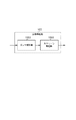
図1は、第1実施形態に適用な画像形成装置の構成例を示すブロック図である。画像形成装置10は、パッチ記録部101、濃度情報取得部102、濃度情報補正部103、ガンマ補正テーブル生成部104、画像処理部105、画像記録部106を含む。画像形成装置10は、外部に接続されたCPUやメモリなどからバスを介してデジタルな入力画像データを取得する。画像形成装置10は、多値画像データに対して各種の処理を施した画像データを記録媒体上に形成する。また、CPUやユーザの指示などにより、適宜ガンマ補正テーブルの作成を行う。なお本実施形態では、多値画像データが8bit(0〜255の256階調からなる)である場合を例に説明する。
Apparatus Configuration FIG. 1 is a block diagram illustrating a configuration example of an image forming apparatus applied to the first embodiment. The
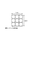
パッチ記録部101は、記録媒体上(若しくは、記録媒体上における出力濃度との相関が分かっている中間記録媒体上)に、濃度パッチを記録する。濃度パッチは、ガンマ補正テーブルを生成するために記録される。図2はパッチ記録部101によって記録される濃度パッチの例を示す。本実施形態における各濃度パッチのサイズは10画素×10画素の大きさを持つ。また、夫々の濃度パッチは、画像処理部105において行われる低階調化処理に応じて予め決定される。本実施形態では、平坦部用濃度パッチ群200、縦細線用濃度パッチ群201、斜め細線用濃度パッチ群202の濃度パッチを記録する。各濃度パッチに関する詳細については、後述する。
The
濃度情報取得部102は、パッチ記録部101によって記録媒体又は中間記録媒体上に記録された濃度パッチの濃度情報を取得する。ここでは、濃度センサを用いて記録媒体上の出力濃度を直接測定し、測定結果を濃度情報として取得する。なお出力濃度の測定方法としては、濃度との相関を持つトナーの高さなど、他の情報を取得することによっても実現可能である。図3は、本実施形態における濃度情報取得部102において用いられる濃度センサの測定範囲を示す。本実施形態に用いられる濃度センサの解像度は、画像データの解像度よりも低いことがわかる。つまり濃度センサによる測定結果は、測定範囲内に対応する画像データを構成する各画素が表す濃度を平均した値に近似する。
The density
濃度情報補正部103は、濃度情報取得部102が取得した濃度情報を補正する。ここでは濃度情報が、縦細線用濃度パッチ群201および斜め細線用濃度パッチ群202を記録した濃度を測定した結果である場合に、濃度情報の補正を行う。濃度情報は、濃度パッチにおける各画素の画素値と濃度パッチを構成するドットパターンが表現する階調との関係に基づいて、補正される。濃度情報補正部103による補正方法の詳細については、後述する。なお、平坦部用濃度パッチ群200による濃度情報に対しては補正を行わない。
The density
ガンマ補正テーブル生成部104は、濃度情報または補正された補正後濃度情報から得られる出力濃度特性に基づいて、ガンマ補正テーブルを生成する。本実施形態では、平坦部用、縦細線用、斜め細線用のガンマ補正テーブルを生成する。
The gamma correction
画像処理部105は、CPUやメモリなどから転送された多値画像データに対して画像処理をする。図4は、本実施形態における画像処理部105の詳細なブロック図を示す。画像処理部105は、細線検出部1051、細線ガンマ補正部1052、ガンマ補正部1053、細線用低階調化処理部1054、スクリーン処理部1055、セレクタ1056を有する。
The
細線検出部1051は、パターンマッチングにより各画素に対して細線を形成する画素かどうかを検出する。
The fine
細線ガンマ補正部1052は、細線検出部1051により細線として検出された画素(以下、細線画素)に対してガンマ補正を行う。細線ガンマ補正部1052では、ガンマ補正テーブル生成部104で作成された縦細線用ガンマ補正テーブルと斜め細線用ガンマ補正テーブルのいずれか一方、又は両方が用いられる。
The fine line
ガンマ補正部1053は、細線ガンマ補正部1052から出力された細線検出部1051により細線として検出されなかった平坦部の画素(以下、平坦画素)に対してガンマ補正を行う。ガンマ補正部1053では、ガンマ補正テーブル生成部104で作成された平坦部用のガンマ補正テーブルが用いられる。
The
細線用低階調化処理部1054は、細線ガンマ補正部1052から出力される細線画素の画素値に対して低階調化処理を行う。細線用低階調化処理部1054における低階調化処理は、後述する画像記録部106が出力可能な画素当りの階調数に合わせて、細線画素を表す画素値の階調数を低減する。前述の通り、画像処理部105に入力される画像データは256階調を表す8bitである。細線用低階調化処理部1054は、256階調をもつ画素値を9階調に変換する9値化を行う。
The fine line gradation
スクリーン処理部1055は、ガンマ補正部1053から出力される平坦画素の画素値に対してスクリーン処理を行う。ここでは、閾値マトリクスを用いたディザ法により階調数を変換する。スクリーン処理部1055は、256階調をもつ画素値を9値化する。
The
セレクタ1056は、細線検出部1051による検出結果に応じて、画像データを画素ごとに振り分ける。処理対象の画素が細線として検出されれば、細線ガンマ補正部1052に、処理対象の画素が細線として検出されなければ、ガンマ補正部1053に、画素毎に画素値を出力する。同様にセレクタ1057は、細線として検出された画素には、細線スクリーン処理部1054の結果を、細線として検出されなかった画素には、スクリーン処理部1055から結果を、それぞれ出力値として選択する。セレクタ1057からは出力画像データが得られる。
The
画像記録部106は、画像処理部105により処理された出力画像データを記録媒体上に記録する。画像記録部016は、インクジェット方式でも電子写真方式でもよい。
The
●画像処理および画像記録動作
本実施形態における画像形成装置が画像を記録する動作を説明する。図5(a)は、画像記録部106が画像を記録する際のフローチャートである。
Image Processing and Image Recording Operation An operation for recording an image by the image forming apparatus according to this embodiment will be described. FIG. 5A is a flowchart when the
ステップS500において、画像形成装置10の外部に接続されたCPUやユーザによる、画像データの印刷指示があるかどうかを判定する。判定の結果、印刷指示がある場合にはステップS501に進む。
In step S <b> 500, it is determined whether there is an instruction to print image data by a CPU or a user connected to the outside of the
ステップS501において、画像形成装置10は記録する入力画像データを取得する。入力画像データは画像形成装置10の外部に接続されたCPUやメモリから入力される。
In step S501, the
ステップS502において、細線検出部1051は細線検出を行う。本実施形態における細線検出部1051では、パターンマッチングによって1画素幅の細線を検出する。図6は、細線検出部1051が検出する細線のパターンと検出条件を示す。細線検出部1051では、縦細線、横細線、斜め細線、その他細線を検出する。
In step S502, the fine
図7(a)は入力画像データの一例である。図7(b)は、上記入力画像データから細線を検出した結果である。図7(b)では、縦細線及び横細線として検出された画素を黒画素、斜め細線として検出された画素を淡グレー画素、その他細線として検出された画素を濃グレー画素、細線以外を白画素として表している。 FIG. 7A shows an example of input image data. FIG. 7B shows the result of detecting a thin line from the input image data. In FIG. 7B, pixels detected as vertical and horizontal thin lines are black pixels, pixels detected as diagonal thin lines are light gray pixels, pixels detected as other thin lines are dark gray pixels, and pixels other than the thin lines are white pixels. It represents as.
ステップS503において、ステップS502における細線検出の結果に基づいて分岐する。処理対象の画素が細線画素でない場合にはステップS504に進み、細線画素である場合にはステップS506に進む。例えば、図7(b)に示す細線検出結果の場合、白画素は細線画素として検出されていないので、ステップS504に進む。一方、画素が白画素以外の場合には細線画素として検出されているためステップS506に進む。本実施形態の画像処理部105では、細線に対する処理と細線以外に対する処理を切り替えて行うが、各画素に対して細線用の処理と細線以外用の処理の両方を行い、細線検出結果に従って、処理結果を選択する構成でもよい。
In step S503, the process branches based on the thin line detection result in step S502. If the pixel to be processed is not a fine line pixel, the process proceeds to step S504, and if it is a thin line pixel, the process proceeds to step S506. For example, in the case of the fine line detection result shown in FIG. 7B, since the white pixel is not detected as the fine line pixel, the process proceeds to step S504. On the other hand, if the pixel is not a white pixel, it is detected as a fine line pixel, and the process advances to step S506. In the
ステップS504において、ガンマ補正部1053は、入力画像データを構成する画素のうち、平坦画素に対してガンマ補正を行う。本実施形態におけるガンマ補正部1053は、平坦部用パッチ200を用いて作成したガンマ補正テーブルを使用してガンマ補正を行う。
In step S504, the
ステップS505においてスクリーン処理部1055は、ディザ法によるスクリーン処理を行う。図8は、スクリーン処理部1055が行うディザ法を説明する図である。画素群に対応するセルには、異なるインデックス番号が格納されている。図8(a)が示すように画像データに対して、セルを隙間なく周期的に並べ、各画素にインデックス番号の何れかを対応させて用いる。インデックス番号は、図8(b)のようにそれぞれ大きさの異なる閾値に対応する。256階調の入力画像データを構成する各画素の画素値と、インデックス番号に対応する閾値とを比較して、各画素の出力値を9階調の何れかに決定する。夫々の閾値TH[n]は、
TH[n]= X * 20 + 1.25 + n * 2.5
(X はインデックス番号)
により算出される。このようなディザ法を用いた処理結果では、セル単位で擬似的に階調表現することができる。一般に、このようなディザ法によれば、(セルが擬似的に表現可能な階調数)=(セル内の画素数)×(セルにおける出力階調数−1)+1となる。つまり本実施形態の例では、スクリーン処理部1055によるスクリーン処理の結果、擬似的に105階調表現できることになる。
In step S505, the
TH [n] = X * 20 + 1.25 + n * 2.5
(X is the index number)
Is calculated by In the processing result using such a dither method, pseudo gradation can be expressed in cell units. In general, according to such a dither method, (the number of gradations that can be expressed in a pseudo manner by the cell) = (the number of pixels in the cell) × (the number of output gradations in the cell−1) +1. That is, in the example of the present embodiment, as a result of the screen processing by the
図7(c)は、図7(a)の入力画像データにスクリーン処理部1055がスクリーン処理を施した結果を示す。なお、図7(c)は、図7(a)の入力画像データを構成する全ての画素に対して処理を行っている。実際には、本実施形態では、図7(b)の検出結果において、白画素となっている画素に対してのみ、処理が行われるものである。
FIG. 7C shows a result of screen processing performed by the
ステップS506において、細線ガンマ補正部1052は細線画素に対して細線ガンマ補正を行う。細線ガンマ補正部1052は、縦細線用のガンマ補正テーブルと斜め細線用のガンマ補正テーブルを用いて、ステップS502で検出した全ての細線に対してガンマ補正を実施する。ステップS502における細線検出の結果、縦細線及び斜め細線と判定された画素については、夫々専用のガンマ補正テーブルを用いてガンマ補正を行えばよい。横細線が検出された場合には、画像形成装置の出力濃度特性が似ている縦細線用のガンマ補正テーブルを使用してガンマ補正する。また、その他細線が検出された場合、その他細線は縦細線又は横細線の出力濃度特性と斜め細線の出力濃度の中間のような出力濃度特性を持つことが推測される。そのため、縦細線用のガンマ補正テーブルと斜め細線用のガンマ補正テーブルを混合して用いることで、その他細線として検出された画素に適したガンマ補正値を算出することができる。
In step S506, the fine line
ステップS507において、細線用低階調化処理部1054は細線画素に対して低階調化処理を実施する。
In step S507, the fine line gradation
図9は、細線用低階調化処理を示す。図9に示すように、細線用低階調化処理部1054は、1つの画素に対して8個の閾値を保持している。細線用低階調化処理部1054は、256階調の入力画像データを構成する画素の画素値と、画素に対応する8個の閾値とを順次比較し、9階調のいずれかを出力値として出力する。このような細線用低階調化処理部1054における低階調化処理によれば、画素単位で階調数を表現するために、スクリーン処理部1055によって得られるセル毎に表現される擬似的な階調数よりも低いが、解像性は維持される。人間の視覚としては、細線のような高周波成分を多く含む領域は階調性よりも解像性が優先される傾向が強い。そのため、細線用低階調化処理部1054における低階調化処理を用いても、細線部における階調性の低下は目立たずに解像性が維持された良好な低階調化画像を得ることが可能である。なお、細線画素に対する低階調化処理は、必ずしも本実施形態に示す処理である必要はないが、平坦部の画素に対して施される低階調化処理よりも解像性を重視した低階調化処理であることが好ましい。
FIG. 9 shows the thin line gradation reduction processing. As shown in FIG. 9, the thin line gradation
ステップS508において、画像記録部106は出力画像データを記録媒体上に記録する。各画素は、ステップS505またはステップS507のいずれかにより、画像記録部16が出力可能な階調数に低減されている。本実施形態では、図7(a)に示す入力画素データは、ステップS505およびステップS507における処理により、図7(d)に示す出力画像データに変換される。平坦部と細線部それぞれに適切なガンマ補正をおこなっているため、記録媒体上に形成される画像は、平坦部と細線の濃度が合った好ましい画像となる。
In step S508, the
●ガンマ補正テーブルの作成に用いられる濃度パッチ
ガンマ補正テーブルを作成するために、パッチ記録部101が記録する濃度パッチについて詳細に説明する。
Density Patch Used to Create Gamma Correction Table The density patch recorded by the
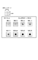
図2は、本実施形態において記録される濃度パッチの一例である。パッチ記録部101は、平坦部濃度パッチ群200、縦細線濃度パッチ群201、斜め細線濃度パッチ202の各濃度パッチを記録する。
FIG. 2 is an example of a density patch recorded in the present embodiment. The
平坦部パッチ群200は、線を含まない平坦な階調を表す入力画像データを記録媒体上に形成した時の出力濃度特性を測定するための濃度パッチである。平坦部パッチ群200は、全ての画素が表す階調値が一定である平坦な入力画像データに対してスクリーン処理部1055がスクリーン処理して得られるドットパターンである。ここではそれぞれ、10画素×10画素の全画素が入力階調値20、38、59、79、100、123、138、159、177、197、218、236、255の一様な入力画像データに対して後述の画像処理部105で施されるスクリーン処理した結果を濃度パッチとする。スクリーン処理の結果得られるドットパターンにおいて、100画素のうち白画素に対する黒画素の割合は、それぞれ順に、8%、15%、23%、31%、39%、46%、54%、62%、69%、77%、85%、92&、100%である。平坦部濃度パッチにおいては、セル毎に擬似的な階調を表現している。また、図3が示す測定範囲においてセンサが測定した結果は、濃度パッチにおける各画素の平均値に近似する。従って、平坦部の出力濃度特性は、センサの測定結果を補正することなく、入力階調値と出力濃度を対応づけることができる。
The flat
縦細線濃度パッチ群201は、縦細線を記録媒体上に形成したときの出力濃度特性を測定するための濃度パッチである。本来、1画素分の幅を持つ縦細線1本を形成する1つの細線画素の出力濃度特性を測定したい。つまり、注目する階調からなる細線が出力された濃度を、注目する階調に対応する出力濃度として測定する必要がある。しかしながら、記録媒体上の出力濃度を測定する際に、縦細線の背景(紙白)を一切含まず、縦細線1本のみの出力濃度を測定することは困難である。また、濃度センサが測定する位置が少しでもずれると、測定範囲に包含される細線画素数が変わり、検出される出力濃度に変動が起こりやすい。そこで本実施形態では、縦細線パッチ群201に示すように、複数の縦細線を周期的に並べた画像を濃度パッチとする。ただし画像形成装置の特性によっては、出力されたドットの濃度は、周囲に記録されたドットの影響を受けることがある。そのため、縦細線パッチ群201の濃度パッチはいずれも、互いに濃度に影響をし合わない程度に離して複数の縦細線を並べている。なお、繰り返されるドットパターンを単位パターンとすると、縦細線パッチ群201における濃度パッチにおいては、縦10画素×横3画素であり左の画素が黒画素である縦細線画像が単位パターンになる。この単位パターンを濃度パッチに必要な縦10画素×横10画素に周期的に並べることで、出力濃度を高くし、測定位置に変動が起きても濃度センサが精度よく測定できるようにしている。縦細線パッチ群201における各濃度パッチはそれぞれ、縦細線が階調33、69、102、136、172、205、238、255の細線画素から構成されている。前述の通り濃度センサによる記録媒体上に記録された濃度の測定結果は、測定範囲内に対応する画像データを構成する各画素が表す濃度を平均した値に近似する。つまり、細線濃度パッチの測定結果は、単位パターンにおける各画素の画素値を平均した値に近似する。本来、測定したい出力濃度は細線を構成する1画素の出力濃度であるが、単位パターンには細線を構成する画素以外の画素(白画素)も含む。そこで、測定結果に対して、単位パターンにおける細線画素の割合を用いて補正する。ここでは、縦細線パッチ群201の濃度パッチでは、いずれも細線画素の割合が1/3である単位パターンを用いているため、測定結果を3倍する補正を行うことにより、縦細線を形成する細線画素あたりの出力濃度を算出することができる。
The vertical fine line
同様に斜め細線濃度パッチ群202は、斜め細線の入力画像データを記録媒体上に形成したときの出力濃度を測定するための濃度パッチである。45度の斜め線一本を構成する画素あたりの出力濃度特性を算出するため、45度の斜め線を周期的に複数本並べた画像を濃度パッチとする。ここで斜め細線パッチ群202の濃度パッチの単位パターンは、4画素×4画素であり、右斜め上方向の対角線上にある4つの画素が黒画素の斜め細線画像である。濃度パッチには4本の斜め細線が含まれる。4本の斜め細線はそれぞれ、互いの濃度に影響を与えない程度に離れている。斜め細線濃度パッチ群202における各濃度パッチはそれぞれ、斜め細線が階調33、69、102、136、172、205、238、255の細線画素から構成されている。斜め細線濃度パッチの測定結果についても、縦細線同様、入力階調値と対応づけるため単位パターンにおける細線画素の割合に応じて測定結果を補正する必要がある。斜め細線濃度パッチ群202の濃度パッチでは、いずれも細線画素の割合が1/4の単位パターンを用いているため、測定結果を4倍する補正を行うことにより、斜め細線を形成する細線画素あたりの出力濃度を算出する。
Similarly, the oblique fine line
なお、どれくらい離れていれば互いの濃度に影響を与えないかは、画像記録部106の特性によって異なる。必要なドット間距離は、実験的に算出することができる。必要なドット間距離に応じて単位パターンを決定すればよい。例えば、必要なドット間距離が3画素である場合、細線用濃度パッチの単位パターンは、縦10画素×横4画素であり、左の画素が黒画素である縦細線画像を単位パターンとすればよい。
It should be noted that how far away there is no influence on each other's density depends on the characteristics of the
●ガンマ補正テーブル作成動作
本実施形態における画像形成装置においてガンマ補正テーブルを作成する場合の動作を説明する。図5(b)は、ガンマ補正テーブルを作成するフローチャートである。
Gamma Correction Table Creation Operation An operation when creating a gamma correction table in the image forming apparatus according to the present embodiment will be described. FIG. 5B is a flowchart for creating a gamma correction table.
ステップS520において、ガンマ補正テーブルを作成するか否かの判定を行う。ガンマ補正テーブルの作成は、画像形成装置10のキャリブレーション時に同時に実施してもよい。また、CPUやユーザによる指示を受けたとき、所定の画像記録枚数を超えたとき、装置が置かれた環境の変化等を感知したときなどに行えばよい。ガンマ補正テーブルを作成するタイミングは任意に設定する。ガンマ補正テーブルを作成する場合はステップS521に進む。
In step S520, it is determined whether to create a gamma correction table. The creation of the gamma correction table may be performed simultaneously with the calibration of the
ステップS524においてパッチ記録部101は、ガンマ補正テーブルを作成するため、所定の濃度パッチ群を選択する。本実施形態の場合、画像処理部105では平坦部用、縦細線用、斜め細線用の3種類のガンマ補正テーブルを使用する。そのため、パッチ記録部101は、平坦部濃度パッチ群200、縦細線濃度パッチ群201、斜め細線濃度パッチ群202からいずれか1つ選択する。図2に示すような濃度パッチはROMやRAMなどの記憶容量中に格納されている。なお、本実施形態における平坦部パッチ群200の濃度パッチ数は、低階調化処理部1055による低階調化処理の結果、擬似的に表現可能な階調数に満たないが、これは測定する濃度パッチの数を削減するためである。
In step S524, the
ステップS525において濃度情報取得部102は、記録媒体上に記録された各濃度パッチの濃度情報を取得する。本実施形態では、図3に示す測定範囲を持つ濃度センサを用いて、各階調に対応する濃度パッチの出力濃度を測定した結果を濃度情報として取得する。平坦部濃度パッチ群を選択している場合、「13」の測定値が濃度情報として得られる。また、縦細線濃度パッチ群、斜め細線濃度パッチ群を選択している場合はそれぞれ、注目する階調に対応して8つの測定値が濃度情報として得られる。前述の通り、本実施形態における濃度センサの解像度は、入力画像の解像度よりも低い。これにより、複数の画素群により表現される擬似的な階調に対応した出力濃度を測定することができる。あるいは、画素単位で階調を表現している場合にも、記録媒体上におけるドット(インク)のにじみやドットゲインを考慮した出力濃度を測定することができる。
In step S525, the density
ステップS526において、選択した濃度パッチ群が平坦部か否かの分岐を行う。ドットパターンが平坦部の場合にはステップS529に、所定ドットパターンが細線の場合にはステップS527に進む。 In step S526, a branch is made as to whether or not the selected density patch group is a flat portion. If the dot pattern is a flat portion, the process proceeds to step S529. If the predetermined dot pattern is a thin line, the process proceeds to step S527.
ステップS527において濃度情報補正部103は、選択した濃度パッチ群が縦細線または斜め細線である場合、より正確な出力濃度特性を算出するためステップS525において取得した濃度情報を補正する。図2に示す縦細線濃度パッチや斜め細線濃度パッチの場合、測定範囲中の出力濃度は、測定範囲がどの位置にあるかによって変化しやすい。しかし、本実施形態のように、濃度センサの測定範囲が細線同士の間隔よりも広く、測定範囲中に複数の細線が含まれる場合には、濃度センサによる測定結果と濃度パッチに占める細線画素の割合はほぼ同じになる。ここでは濃度パッチに占める細線画素の割合を、濃度パッチに繰り返し配置されている単位パターンに占める細線画素の割合とする。縦細線パッチ群201では、細線画素の割合が1/3、斜め細線パッチ群202では細線画素の割合は1/4である。前述の通り、各入力階調に対応する濃度情報に対して、細線画素の割合の逆数を乗じることで、より正確に入力階調に対応する出力濃度を算出する。
In step S527, when the selected density patch group is a vertical thin line or a diagonal thin line, the density
図10(a)は、縦細線濃度パッチ群202を測定した結果を示す。図中のプロット「●」は、縦細線用濃度パッチ群をセンサが測定した測定値である。この測定値が濃度情報として保持される。ステップS527において濃度情報補正部103が補正すると、プロット「×」で示された補正値が得られる。なお図10(a)に示す補正値には、出力濃度が100%を超える領域が存在する。これは、記録媒体上におけるドットゲイン現象により入力画像データの画素以上の範囲にドットが記録されているために起こる。
FIG. 10A shows the result of measuring the vertical thin line
ステップS529において、濃度情報または補正された濃度情報に基づいて出力濃度特性を算出し、ガンマ補正テーブルを生成する。例えば、縦細線用のガンマ補正テーブルを作成する場合を例に説明する。縦細線用の場合、濃度情報を補正した補正値が、各入力階調値に対応する出力濃度である。得られた複数の出力濃度に従って、測定していない入力階調値に対する出力濃度を補間する。図10(a)の実線は、補間した結果を示す。図10(a)の実線が、縦細線を構成する画素の出力濃度特性である。この図10(a)の実線に対し、入力階調値と出力濃度の座標軸を入れ替えることで得られる図10(b)の破線がガンマ補正テーブルとなる。なお、低濃度領域及び高濃度領域などの測定値の信頼性の低い領域において補正テーブルを修正し、図10(b)の実線のようなガンマ補正テーブルを生成してもよい。 In step S529, an output density characteristic is calculated based on the density information or the corrected density information, and a gamma correction table is generated. For example, a case where a gamma correction table for vertical thin lines is created will be described as an example. In the case of the vertical thin line, the correction value obtained by correcting the density information is the output density corresponding to each input gradation value. According to the obtained plurality of output densities, the output density with respect to the input grayscale value not measured is interpolated. The solid line in FIG. 10A shows the result of interpolation. The solid line in FIG. 10A is the output density characteristic of the pixels constituting the vertical thin line. A broken line in FIG. 10B obtained by switching the coordinate axis of the input gradation value and the output density with respect to the solid line in FIG. 10A is the gamma correction table. It should be noted that the correction table may be modified in a low-reliability region such as a low-concentration region and a high-concentration region to generate a gamma correction table such as the solid line in FIG.
ステップS530において、全ガンマ補正テーブルの作成を終了したかを判定する。本実施形態では、平坦部、縦細線、斜め細線に関して、ガンマ補正テーブルの作成が終了していない場合には、他のガンマ補正テーブルを作成するためステップS520に進む。 In step S530, it is determined whether the creation of all gamma correction tables has been completed. In the present embodiment, when the creation of the gamma correction table is not completed for the flat portion, the vertical thin line, and the diagonal thin line, the process proceeds to step S520 to create another gamma correction table.
以上のように、本実施形態におけるガンマ補正テーブル作成方法では、より正確に入力階調に対応する出力濃度を算出するために、センサにより測定して得られる濃度情報を補正する。これにより精度よく出力濃度特性を得られ、より適切なガンマ補正テーブルを作成することができる。 As described above, in the gamma correction table creation method according to the present embodiment, the density information obtained by measurement with the sensor is corrected in order to calculate the output density corresponding to the input gradation more accurately. As a result, the output density characteristic can be obtained with high accuracy, and a more appropriate gamma correction table can be created.
また、濃度センサが測定するための濃度パッチにおいて、細線の単位パターンを繰り返し複数の細線を配置している。これにより、濃度センサの測定位置が取りつけ誤差等によってずれていても、測定範囲内に含まれるドットの割合は変わらない。つまり、本実施形態のように単位パターンを繰り返し配置した濃度パッチを用いることで、センサと濃度パッチの相対位置に対する変動の少ない測定値を得ることが可能となる。ただし、濃度パッチにおいて単位パターンに含まれるドットは、他の単位パターンに含まれるドットから濃度に影響をうけない程度に配置されている。 Further, in the density patch for measurement by the density sensor, a plurality of fine lines are arranged by repeating the unit pattern of fine lines. Thereby, even if the measurement position of the density sensor is shifted due to an attachment error or the like, the proportion of dots included in the measurement range does not change. That is, by using the density patch in which the unit patterns are repeatedly arranged as in the present embodiment, it is possible to obtain a measurement value with little variation with respect to the relative position of the sensor and the density patch. However, the dots included in the unit pattern in the density patch are arranged so as not to affect the density from the dots included in other unit patterns.
また、本実施形態に示した測定結果の補正により、画素単位で階調を表している場合でも、ある入力階調を表す画素あたりの出力濃度を算出することができる。具体的には、ドットパターンにおける各画素の画素値とドットパターンが表現する階調との関係に基づいて、測定結果を補正する。その結果本実施形態によれば、従来使用してきた低解像度の濃度センサを用いて、測定しにくい細線画像の出力濃度も適切に取得できる。これにより、細線用のガンマ補正テーブルを作成するために、新たなセンサを追加するなどのコストアップを抑制することができる。 Further, by correcting the measurement results shown in this embodiment, even when the gradation is expressed in units of pixels, the output density per pixel that represents a certain input gradation can be calculated. Specifically, the measurement result is corrected based on the relationship between the pixel value of each pixel in the dot pattern and the gradation expressed by the dot pattern. As a result, according to the present embodiment, it is possible to appropriately acquire the output density of a thin line image that is difficult to measure by using a conventionally used low-resolution density sensor. Accordingly, it is possible to suppress an increase in cost such as adding a new sensor in order to create a gamma correction table for fine lines.
<第2実施形態>
第2実施形態では、孤立点に対するガンマ補正テーブル作成について説明する。また前述の実施形態とは異なり、画像データと同程度の解像度をもつ高解像度な濃度センサを用いて、ガンマ補正テーブル作成する例について説明する。なお、第1実施形態と同様の構成については、同じ符号を付し、詳細な説明を省略する。
Second Embodiment
In the second embodiment, creation of a gamma correction table for isolated points will be described. Unlike the above-described embodiment, an example of creating a gamma correction table using a high-resolution density sensor having a resolution comparable to that of image data will be described. In addition, about the structure similar to 1st Embodiment, the same code | symbol is attached | subjected and detailed description is abbreviate | omitted.
●装置構成
本実施形態では、画像処理部105において、平坦部用のガンマ補正テーブルと孤立点用のガンマ補正テーブルを使用する。そこで、ガンマ補正テーブル生成部104は、平坦部用と孤立点用の2種類のガンマ補正テーブルを作成する。ガンマ補正テーブルを作成するためにパッチ記録部が記録するドットパターンは、平坦部用の場合、図2の平坦部濃度パッチ群200である。一方で、孤立点用のガンマ補正テーブルを作成する際には、図11に示す孤立点濃度パッチ群を使用する。
Apparatus Configuration In this embodiment, the
図12は、第2実施形態に適用可能な画像処理部105の詳細なブロック図を示す。本実施形態における画像処理部105は、ガンマ補正部1053、スクリーン処理部1055、孤立点検出部1057、孤立点ガンマ補正部1058、セレクタ1059、1060を含む。
FIG. 12 is a detailed block diagram of the
本実施形態におけるガンマ補正部1058およびスクリーン処理部1055は、画素ごとの特徴に関わらず、全画素に対してそれぞれガンマ補正、スクリーン処理を行う。
The
孤立点検出部1057は、スクリーン処理部1055の処理結果から孤立点となる画素を検出する。
The isolated
セレクタ1059は、セレクタ1059は、孤立点検出部1057の判定結果に基づいて、画素毎にセレクタ1060か孤立点ガンマ補正部1058のいずれかに出力する。
The
孤立点ガンマ補正部1058は、孤立点検出1057が孤立点として検出した画素に対して、スクリーン処理部1055により処理された処理結果をさらに、孤立点用ガンマ補正テーブルを用いてガンマ補正をおこなう。
The isolated point
セレクタ1060は、孤立点として検出された画素については、孤立点ガンマ補正部1058からの出力値を、それ以外の画素についてはスクリーン処理部1055からの出力値を画素毎に選択し、出力画像データを出力する。
The selector 1060 selects, for each pixel, the output value from the isolated point
本実施形態における画像形成装置において、画像記録動作とガンマ補正テーブル作成動作を説明する。図13(a)は画像記録動作のフローチャートを、図13(b)はガンマ補正テーブル作成動作のフローチャートを示す。 An image recording operation and a gamma correction table creating operation in the image forming apparatus according to the present embodiment will be described. FIG. 13A shows a flowchart of the image recording operation, and FIG. 13B shows a flowchart of the gamma correction table creation operation.
<画像記録動作>
本実施形態では、画像データが開始されると、ステップS501において入力画像データを取得する。その後、ステップS504においてガンマ補正部1053は全画素に対して平坦部用ガンマ補正を行い、ステップS505においてスクリーン処理部1055は、スクリーン処理を行う。
<Image recording operation>
In this embodiment, when image data is started, input image data is acquired in step S501. Thereafter, in step S504, the
ステップS509において、孤立点検出部1057はスクリーン処理の結果から孤立点を検出する。図14は孤立点として検出する条件を示す。孤立点となるのは、スクリーン処理結果のうち、処理画素の出力値が0より大きく、その周囲画素の出力値がすべて0となる画素である。
In step S509, the isolated
ステップS510において、ステップS509における孤立点検出の結果に基づいて画素毎に分岐する。処理対象画素が孤立点と判定された場合にはステップS511に進み、孤立点でない場合にはステップS508に進む。 In step S510, the process branches for each pixel based on the result of the isolated point detection in step S509. If it is determined that the pixel to be processed is an isolated point, the process proceeds to step S511, and if it is not an isolated point, the process proceeds to step S508.
ステップS511において孤立点ガンマ補正部1058は、孤立点の画素に対して孤立点ガンマ補正をおこなう。本実施形態の孤立点ガンマ補正部1058では、孤立点用のガンマ補正テーブルを使用してガンマ補正を行う。但し、孤立点補正部1058に入力される処理対象画素の画素値はすでに、ガンマ補正部1053によって平坦部用ガンマ補正が施されており、平坦部のスクリーン処理の出力濃度が合うように画像データが変換されている。従って、ここで使用する孤立点用のガンマ補正テーブルは、平坦部用ガンマ補正の効果をキャンセルした上で、孤立点の出力濃度が合うように作成されたものである。
In step S511, the isolated point
ステップS508において、セレクタ10659から出力される出力画像データを記録する。特に、画像記録部106が電子写真方式を利用して記録媒体上に画像を記録する場合、孤立点の形成が不安定になりやすい。そのため、上記の処理フローのようにスクリーン処理の結果から孤立点を検出してガンマ補正することで、精度良く孤立点の出力濃度を調整することができる。
In step S508, the output image data output from the selector 10659 is recorded. In particular, when the
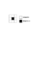
<孤立点濃度パッチ>
図11は孤立点用ガンマ補正テーブルを作成するために記録される濃度パッチ群を示す。本実施形態における孤立点濃度パッチ群203は、3画素×3画素からなる。ここでは高解像センサを用いて孤立点の濃度パッチを測定する。インクのにじみやドットゲインを考慮した出力濃度を測定するため、孤立点である画素とその周囲8画素を含むように測定するのがよい。平坦部濃度パッチ群200の濃度パッチに比べて、孤立点の濃度パッチは測定に必要な最小限までサイズを小さくすることで、ガンマ補正テーブル作成にかかる時間を短縮できる。例えば、孤立点用のガンマ補正テーブル作成のために、第1実施形態と同様に10画素×10画素の濃度パッチを階調数分逐次的に低解像度センサで濃度情報を取得することを考える。この場合と比較すると、本実施形態のように高解像度センサを用いた場合は、濃度パッチが3画素×3画素程度のサイズで済むために濃度パッチ記録にかかる時間は3/10に短縮される。また、パッチの記録に使用する面積は9/100に削減される。なお、高解像度センサは図15に示す全測定箇所を同時に取得できるように複数の濃度センサから構成されていてもよいし、測定箇所よりも少ないセンサ数で測定回数を増やして全測定箇所の濃度情報を取得してもよい。
<Isolated point density patch>
FIG. 11 shows a group of density patches recorded in order to create an isolated point gamma correction table. The isolated point density patch group 203 in this embodiment is composed of 3 pixels × 3 pixels. Here, a density patch of an isolated point is measured using a high resolution sensor. In order to measure the output density in consideration of ink bleeding and dot gain, it is preferable to measure so as to include pixels that are isolated points and the surrounding eight pixels. Compared with the density patch of the flat part
●ガンマ補正テーブル作成動作
本実施形態で作成するガンマ補正テーブルは、平坦部用と孤立点用の2種類である。図13(b)は、各ガンマ補正テーブルを作成する処理のフローチャートである。
Gamma correction table creation operation There are two types of gamma correction tables created in this embodiment, one for flat portions and one for isolated points. FIG. 13B is a flowchart of processing for creating each gamma correction table.
ステップS531において、パッチ記録部101は、全ドットパターンのガンマ補正テーブルを作成するかどうかで分岐する。全ドットパターンのガンマ補正テーブルを作成する場合、ステップS5244に進み、パッチ記録部101は平坦部用濃度パッチ群200か図11が示す孤立点用濃度パッチ群203のいずれかを選択する。さらにパッチ記録部101は、選択した濃度パッチ群の濃度パッチを記録媒体上に記録する。
In step S531, the
ステップS532において、平坦部用と孤立点用のいずれかの補正テーブルを作成しているかで分岐する。平坦部用のガンマ補正テーブルを作成する場合にはステップS533に進み、孤立点用のガンマ補正テーブルを作成する場合にはステップS534に進む。 In step S532, the process branches depending on whether a correction table for a flat portion or an isolated point is created. If a gamma correction table for a flat portion is to be created, the process proceeds to step S533, and if a gamma correction table for an isolated point is to be created, the process proceeds to step S534.
ステップS533において、平坦部用のガンマ補正テーブル作成のため、ステップS524で記録した濃度パッチの濃度情報を低解像度な濃度センサによる濃度情報取得手段により取得する。これは第1実施形態で示した、ステップS525による濃度情報取得手段と同様に、図2に示す平坦部用のパッチ群200を図3に示す測定範囲を持つ低解像度の濃度センサによって測定した結果である。
In step S533, the density information of the density patch recorded in step S524 is acquired by density information acquisition means using a low-resolution density sensor in order to create a gamma correction table for the flat portion. This is the result of measuring the flat
ステップS534において、孤立点用のガンマ補正テーブル作成のため、図11に示す孤立点パッチ群が記録された濃度パッチを、図15に示す測定範囲を持つ高解像度な濃度センサによって測定する。高解像度の濃度センサにより濃度パッチを測定する場合、測定範囲が画像データの画素面積以下であるため、図15に示す濃度パッチ中における各画素に対応する測定値を取得し、複数の測定値を平均化することで濃度情報とする。これは前述の通り、ドットパターンが孤立点の場合にも、記録媒体上に記録されるドットは周囲へもにじんで記録されるので、このように周囲画素まで濃度情報を取得するためである。 In step S534, in order to create a gamma correction table for isolated points, the density patch in which the isolated point patch group shown in FIG. 11 is recorded is measured by a high-resolution density sensor having the measurement range shown in FIG. When measuring a density patch with a high-resolution density sensor, since the measurement range is less than or equal to the pixel area of the image data, a measurement value corresponding to each pixel in the density patch shown in FIG. 15 is acquired, and a plurality of measurement values are obtained. The density information is obtained by averaging. This is because, as described above, even when the dot pattern is an isolated point, the dots recorded on the recording medium are also recorded in the periphery, and thus density information is acquired up to the surrounding pixels.
ステップS527において、ステップS534で得た濃度情報を、測定範囲中のドットパターンにおける孤立点を形成する画素の割合を用いて補正する。図15に示す高解像度センサによる測定範囲は3画素×3画素分であるが、このうち、図11に占めす孤立点のドットパターンは1画素のみであるため、濃度情報を取得する範囲に占めるドットパターンの割合は1/9である。この逆数を乗じることで濃度情報を補正する。 In step S527, the density information obtained in step S534 is corrected using the ratio of pixels that form isolated points in the dot pattern in the measurement range. The measurement range by the high-resolution sensor shown in FIG. 15 is 3 pixels × 3 pixels. Of these, the dot pattern of the isolated points that occupy in FIG. 11 is only one pixel, and therefore occupies the range in which density information is acquired. The ratio of the dot pattern is 1/9. The density information is corrected by multiplying the inverse.
ステップS529において、濃度情報と対応する孤立点の入力階調を基に、夫々のドットパターンのガンマ補正テーブルが生成される。但し、本実施形態の画像処理部105において、孤立点用ガンマ補正は平坦部用のガンマ補正がなされた画像データに対してガンマ補正が行われる。そのため、孤立点用のガンマ補正テーブル作成の際は、平坦部用のガンマ補正をキャンセルするように平坦部用のガンマ補正テーブルを逆変換して作成したデガンマ補正テーブルと孤立点用のガンマ補正を行う補正テーブルを合成して生成する。なお、平坦部と孤立点領域の濃度不連続を防止するため、合成した補正テーブルの階調100%の値は常に100%になるように出力レンジを調整する。
In step S529, a gamma correction table for each dot pattern is generated based on the input tone of the isolated point corresponding to the density information. However, in the
ステップS530において、平坦部用と孤立点用のガンマ補正テーブルの作成が終了するまで、ステップS524に戻り上記処理フローを繰り返す。 In step S530, the process returns to step S524 and the above processing flow is repeated until the creation of the gamma correction table for the flat portion and the isolated point is completed.
次に、ステップS535により孤立点用のガンマ補正テーブルのみを作成する場合の処理フローが選択された場合であるが、これは上記で説明した孤立点用のガンマ補正テーブル作成と同一の処理フローとなっている。 Next, the processing flow in the case where only the isolated point gamma correction table is created in step S535 is selected. This is the same processing flow as that for creating the isolated point gamma correction table described above. It has become.
以上のように、孤立点用と平坦部用の補正テーブルを同時に作成する処理フローと、孤立点用の補正テーブルのみを作成する処理フローを異なるタイミングで実行する例を説明した。画像形成装置では特に孤立点の変動が大きいため、上記のような構成とすることで、孤立点用のガンマ補正テーブルの作成頻度を従来のガンマ補正テーブル作成頻度より多くし、画像形成装置の状態に合せた精度の高い補正テーブルが作成可能となる。また、作成頻度が多くなる孤立点用の補正テーブル作成のために、高解像度センサを用いることで補正テーブル作成にかかる時間および記録媒体上の面積を短縮できることも示した。 As described above, an example has been described in which the processing flow for simultaneously creating the correction table for isolated points and the flat portion and the processing flow for creating only the correction table for isolated points are executed at different timings. Since the variation of isolated points is particularly large in an image forming apparatus, the above configuration increases the frequency of creating a gamma correction table for isolated points from the conventional gamma correction table creation frequency, and the state of the image forming apparatus. It is possible to create a correction table with high accuracy according to the above. It has also been shown that the time required to create the correction table and the area on the recording medium can be shortened by using a high-resolution sensor in order to create a correction table for isolated points that are frequently created.
<第3実施形態>
本発明に係るガンマ補正テーブル作成方法の第3実施形態として、低濃度部の平坦部高密度濃度パッチを測定した結果を適正に補正し、平坦部用のガンマ補正テーブルの精度を向上させる例を以下に説明する。
<Third Embodiment>
As a third embodiment of the method for creating a gamma correction table according to the present invention, an example of appropriately correcting the measurement result of the flat portion high density patch of the low density portion and improving the accuracy of the gamma correction table for the flat portion. This will be described below.
●装置構成
第3実施形態の画像形成装置の構成は、図1に示す第1実施形態の画像形成装置の構成と同様であるため、説明は一部省略する。
Apparatus Configuration The configuration of the image forming apparatus of the third embodiment is the same as the configuration of the image forming apparatus of the first embodiment shown in FIG.
図16は、本実施形態の画像処理部105の詳細なブロック図を示す。本実施形態における画像処理部105は、ガンマ補正部1053、スクリーン処理部1055を含む。
FIG. 16 shows a detailed block diagram of the
ガンマ補正部1053では、平坦部用のガンマ補正テーブルを基に画像データのガンマ変換を行う。
The
スクリーン処理部1055では、図8に示すようなスクリーン処理を施す。前述の通り、スクリーン処理して得られるドットパターンは、複数の画素からなるセル単位で階調を擬似的に表している。
The
上記のように本実施形態における画像処理部105は、一つのガンマ補正テーブルのみを用いてガンマ補正を行う。パッチ記録部は、図17が示す濃度パッチ群を用いて記録媒体上に濃度パッチを記録し、これを測定した結果に基づいてガンマ補正テーブル生成部104においてガンマ補正テーブルを作成する。図17に示す濃度パッチ群は、図2に示す平坦部パッチ群200のうち、低濃度である濃度パッチを高密度濃度パッチ群1700に置換したものである。ここで高密度濃度パッチ群1700に置換される低濃度な濃度パッチは、階調20を表すドットパターンと階調38を表すドットパターンである。高密度濃度パッチは、図2が示す低濃度に対応する濃度パッチよりも、ドットの密度が高いことが特徴である。高密度濃度パッチの作成方法については後述する。
As described above, the
図2に示す平坦部パッチ群200の低濃度な階調を表すドットパターンは、ドット密度が小さく、図3に示すような低解像度センサの測定範囲がずれた場合に、測定範囲中のドット数が変わり、測定濃度も変わってしまう。そこで、ドット密度の高い高密度濃度パッチを記録媒体上に記録し、低解像度センサの測定位置が多少ずれても、ほぼ同数のドットがその測定範囲内に包含されるようにする。これにより、濃度センサの位置ずれによる影響が少ない測定結果を可能にする。また、濃度センサによって測定した結果には、センサノイズや記録媒体の下地表面粗さや濃度のばらつきなどによるノイズを含む。そのため、低濃度な階調に対応する濃度パッチにおいては、出力濃度が小さいため、相対的にノイズの影響が大きくなり有効な測定値を得られない可能性がある。本実施形態の場合、低濃度部分に高密度濃度パッチを使用することで、前述のようなノイズによる影響を相対的に小さくすることができる。測定した結果は、濃度情報補正部103によって補正され、精度の良いガンマ補正テーブル生成を作成できる。
The dot pattern representing the low density gradation of the
高密度濃度パッチの作成方法を詳細に説明する。図2に示す平坦部パッチ群200のドットパターンは、階調が一定な平坦画像に対して図8に示すスクリーン処理を施した結果に従って形成されている。従って、濃度パッチにおいては、セルごとにドットの数、出現位置は同一である。高密度濃度パッチ群は、低濃度に対応するドットパターンのドット形状は維持したまま、ドットをより高密度に配置したものである。具体的には、図18に示す隣接セルにおけるドット間距離L0、L0’をL1、L1’に縮めることで作成している。ドット間の距離を縮めることで、ドットパターンを形成するセルの一部は重複領域を持つため、濃度パッチに占めるドットの割合は元の濃度パッチよりも増大する。濃度パッチに占めるドットの割合は、ドット間距離の比から算出することが可能であり、(L0×L0’/L1×L1’)となる。つまり、高密度濃度パッチにおけるドット密度は、通常用いられる濃度パッチにおけるドット密度の(L0×L0’/L1×L1’)倍であると言える。例えば、階調20に対応する高密度濃度パッチにおけるドット密度は、図2における階調20に対応する濃度パッチの約2.6倍、階調38に対応する濃度パッチの約1、6倍となる。なお、高密度濃度パッチを作成するためにドット間の距離を近づけすぎると、互いのドットの出力濃度への影響を及ぼしてしまう。高密度濃度パッチでは、ドット同士が互いの出力濃度に影響を与えない程度に離れている必要がある。本実施形態では、2画素以上離して高密度濃度パッチのドットパターンを作成している。なお、どれくらいドット同士を離して配置すべきかについては、実験的に求めることができる。このように高密度濃度パッチは、セルを単位ドットパターンとして、周期的かつ重複するように配置することで、出力濃度をあげている。また、互いに影響を及ぼさない程度にドット同士が離れているため、補正により、本来算出したい濃度パッチの出力濃度を算出することができる。
A method of creating a high density patch will be described in detail. The dot pattern of the
図19は本実施形態の画像形成装置における処理フローチャートを示す。図19に示す夫々のステップが、図5及び図13に示す処理フローチャートのステップと同名・同符号のものは同一のステップであるため、説明を省略する。 FIG. 19 shows a processing flowchart in the image forming apparatus of this embodiment. Since each step shown in FIG. 19 has the same name and the same sign as the step of the processing flowchart shown in FIG. 5 and FIG. 13, description thereof will be omitted.
●画像記録動作
本実施形態での画像記録動作時は、画像データを取得し、ガンマ補正、スクリーン処理を施して、画像データを記録する。各ステップについての説明は省略する。
Image Recording Operation During the image recording operation in this embodiment, image data is acquired, subjected to gamma correction and screen processing, and image data is recorded. A description of each step is omitted.
●ガンマ補正テーブル作成動作
図19(b)に示す処理フローチャートを用いて、本実施形態におけるガンマ補正テーブル作成動作を説明する。
Gamma Correction Table Creation Operation The gamma correction table creation operation in this embodiment will be described using the processing flowchart shown in FIG.
ステップS520において、ガンマ補正テーブルの作成が開始される。 In step S520, creation of a gamma correction table is started.
ステップS524において、パッチ記録部101は、濃度パッチ群を選択し、記録媒体上に記録する。本実施形態では、図17に示す濃度パッチ群を選択する。低濃度な階調に対応する濃度パッチ1700は、高密度にドットが配置された高密度濃度パッチである。ステップS525において、濃度情報取得部102は記録媒体上に記録された濃度パッチを、濃度センサを用いて測定した結果を濃度情報として取得する。本実施形態では上、図3に示すような測定範囲を持つ濃度センサを用いる。ここでは、異なる階調に対応する13の濃度情報が得られる。
In step S524, the
ステップS536において、濃度情報補正部103は取得した濃度情報毎に、濃度情報を補正するかしないかを判定する。処理対象の濃度情報に対応する階調値が所定値以下か否かにより、判定する。ここで所定値とするのは、予め作成しておいた高密度濃度パッチに対応する階調値とする。
In step S536, the density
ステップS527において、濃度情報補正部103は、ステップS536において調値が所定値以下と判定された濃度情報、すなわち、高密度濃度パッチについて測定した結果である濃度情報を補正する。高密度濃度パッチ群1700の場合、本来測定したいドットパターンよりも高密度にドットを配置している。なお、本来測定したいドットパターンとは、スクリーン処理部1055によるスクリーン処理によって得られるドットパターンである。そのために、取得した濃度情報を補正する必要がある。前述の通り、階調20に対応する高密度濃度パッチにおけるドット密度は、図2における階調20に対応する濃度パッチの約2.6倍、階調38に対応する濃度パッチの約1、6倍となる。また、それぞれの高密度濃度パッチは、互いのドットの出力濃度に影響を与えない。そこで、取得した濃度情報に対して、階調20に対応する濃度情報は2.6倍の逆数、階調38に対応する濃度情報には1.6の逆数を乗じることにより、本来取得したい出力濃度を算出することができる。図20(a)は濃度情報取得部によって得られた各階調値に対する測定値と、濃度情報補正部によって得られる補正値を示す。
In step S527, the density
ステップS528において、全階調分の測定が終了すると、ステップS529において、ガンマ補正テーブル生成部104はガンマ補正テーブルを生成する。図20(a)に示す実線は、測定値と補正値から得られた出力濃度特性である。出力濃度を測定していない階調については補間によって曲線を求めている。この出力濃度特性を逆変換することで、より適切なガンマ補正テーブルを作成することができる。図20(b)は本実施形態により作成されたガンマ補正テーブルを示す。
When the measurement for all the gradations is completed in step S528, the gamma correction
以上、本実施形態では、濃度情報を取得する範囲に占めるドットパターンの割合によって濃度情報を補正することで、ガンマ補正テーブルの低濃度部の精度を高めることが可能なガンマ補正テーブルの作成方法を説明した。 As described above, in the present embodiment, there is provided a method for creating a gamma correction table that can improve the accuracy of the low density portion of the gamma correction table by correcting the density information based on the ratio of the dot pattern in the density information acquisition range. explained.
本実施形態では、ドット集中型のスクリーン処理を例に説明したが、ドット分散型のスクリーン処理でも同様の効果を得ることができる。 In the present embodiment, the dot concentration type screen processing has been described as an example, but the same effect can be obtained by dot dispersion type screen processing.
<その他の実施形態>
なお前述の実施形態では、画像記録部106とは別にパッチ記録部101を構成とした。しかしながら、濃度パッチの測定を記録媒体上において行う場合は、画像記録部106が濃度パッチの記録を行う構成でもよい。
<Other embodiments>
In the above-described embodiment, the
本発明は、上述した実施例の機能を実現するソフトウェアのコンピュータプログラムコードを記録した記憶媒体を、システム或いは装置に供給することによっても実現できる。この場合、そのシステム或いは装置のコンピュータ(又はCPUやMPU)がコンピュータが読み取り可能に記憶媒体に格納されたコンピュータプログラムコードを読み出し実行することにより、上述した実施例の機能を実現する。 The present invention can also be realized by supplying a storage medium storing a computer program code of software for realizing the functions of the above-described embodiments to a system or apparatus. In this case, the computer (or CPU or MPU) of the system or apparatus reads out and executes the computer program code stored in the storage medium so that the computer can read the functions of the above-described embodiments.
Claims (10)
前記補正手段が、複数の縦細線画像を周期的に配置した細線濃度パッチの1つの縦細線画像を単位パターンとし、前記単位パターンにおける細線画素の割合を用いて、前記細線濃度パッチの測定結果である濃度情報を補正することにより、前記縦細線画像を形成する細線画素あたりの出力濃度を求める補正工程と、
前記ガンマ補正テーブル生成手段が、前記出力濃度に基づいて、ガンマ補正テーブルを生成するガンマ補正テーブル生成工程と
を有することを特徴とするガンマ補正テーブル作成方法。 A gamma correction table creation method in the image forming apparatus, which creates a gamma correction table based on a result of measuring a density patch output from an image forming apparatus having a correction unit and a gamma correction table generation unit,
The correction means uses one vertical fine line image of fine line density patches in which a plurality of vertical fine line images are periodically arranged as a unit pattern, and uses the ratio of the fine line pixels in the unit pattern as a measurement result of the fine line density patch. A correction step for obtaining output density per fine line pixel forming the vertical fine line image by correcting certain density information;
A gamma correction table creation method, wherein the gamma correction table generation means includes a gamma correction table generation step of generating a gamma correction table based on the output density.
前記取得手段が、画像形成装置が出力した、階調を表す単位となるセルの一部が重複するように配置された高密度濃度パッチを、読み取りセンサが前記セルよりも広い範囲で読み取ることにより濃度情報を取得する取得工程と、
前記補正手段が、前記高密度濃度パッチにおける前記セルの数に応じて、前記濃度情報を補正する補正工程と、
前記ガンマ補正テーブル生成手段が、前記補正された濃度情報に基づいて、ガンマ補正テーブルを生成するガンマ補正テーブル生成工程と
を有することを特徴とするガンマ補正テーブル作成方法。 A gamma table creation method in an image forming apparatus having an acquisition unit, a correction unit, and a gamma correction table generation unit,
When the acquisition unit reads out the high density patch, which is output from the image forming apparatus and is arranged so that a part of cells serving as a unit representing gradation is overlapped, in a wider range than the cell. An acquisition process for acquiring concentration information;
A correction step in which the correction means corrects the density information according to the number of cells in the high-density patch;
A gamma correction table generating method, wherein the gamma correction table generating means includes a gamma correction table generating step of generating a gamma correction table based on the corrected density information.
前記保持手段が、前記セルが低濃度を表す場合には、前記高密度濃度パッチを保持し、前記セルが高濃度を表す場合には、前記セルを重複しないように配置した濃度パッチを保持する保持工程を有し、
前記補正手段が、前記高密度濃度パッチに対応する濃度情報に対してのみ補正を行い、
前記ガンマ補正テーブル生成手段が、前記濃度情報と前記補正工程による結果とから前記ガンマ補正テーブルを作成することを特徴とする請求項2または3に記載のガンマ補正テーブル作成方法。 The image forming apparatus further includes a holding unit,
The holding unit holds the high-density patch when the cell represents a low density, and holds the density patch arranged so as not to overlap the cell when the cell represents a high density. Having a holding step,
The correction unit corrects only the density information corresponding to the high-density patch,
4. The gamma correction table creation method according to claim 2, wherein the gamma correction table creation unit creates the gamma correction table from the density information and a result of the correction process.
Priority Applications (4)
| Application Number | Priority Date | Filing Date | Title |
|---|---|---|---|
| JP2012261311A JP6099952B2 (en) | 2012-11-29 | 2012-11-29 | Gamma correction table creation method, or image processing method using gamma correction table and control method thereof |
| US14/088,836 US9258457B2 (en) | 2012-11-29 | 2013-11-25 | Gamma correction table generation method or image processing method using gamma correction table and control method thereof |
| CN201310628978.8A CN103856681B (en) | 2012-11-29 | 2013-11-29 | Gamma correction table generation method and image processing apparatus |
| US14/989,287 US9406005B2 (en) | 2012-11-29 | 2016-01-06 | Gamma correction table generation method, image processing device using the gamma correction table and control program thereof |
Applications Claiming Priority (1)
| Application Number | Priority Date | Filing Date | Title |
|---|---|---|---|
| JP2012261311A JP6099952B2 (en) | 2012-11-29 | 2012-11-29 | Gamma correction table creation method, or image processing method using gamma correction table and control method thereof |
Publications (3)
| Publication Number | Publication Date |
|---|---|
| JP2014107813A JP2014107813A (en) | 2014-06-09 |
| JP2014107813A5 JP2014107813A5 (en) | 2016-01-21 |
| JP6099952B2 true JP6099952B2 (en) | 2017-03-22 |
Family
ID=50773049
Family Applications (1)
| Application Number | Title | Priority Date | Filing Date |
|---|---|---|---|
| JP2012261311A Active JP6099952B2 (en) | 2012-11-29 | 2012-11-29 | Gamma correction table creation method, or image processing method using gamma correction table and control method thereof |
Country Status (3)
| Country | Link |
|---|---|
| US (2) | US9258457B2 (en) |
| JP (1) | JP6099952B2 (en) |
| CN (1) | CN103856681B (en) |
Families Citing this family (6)
| Publication number | Priority date | Publication date | Assignee | Title |
|---|---|---|---|---|
| US9475321B2 (en) * | 2014-07-31 | 2016-10-25 | Canon Kabushiki Kaisha | Image processing apparatus, image processing method and medium |
| US9498993B2 (en) * | 2014-07-31 | 2016-11-22 | Canon Kabushiki Kaisha | Image processing apparatus, image processing method, and medium storing program |
| JP6150078B2 (en) * | 2014-12-18 | 2017-06-21 | コニカミノルタ株式会社 | Image forming apparatus, image forming system, and image forming control method |
| JP2016142858A (en) * | 2015-01-30 | 2016-08-08 | ブラザー工業株式会社 | Image formation apparatus, control method and program |
| CN108572178A (en) * | 2018-04-10 | 2018-09-25 | 苏州久越金属科技有限公司 | A kind of high-accuracy high stability detection method |
| CN109166560B (en) * | 2018-08-16 | 2020-05-19 | 广州视源电子科技股份有限公司 | Gamma correction method, device, equipment and storage medium |
Family Cites Families (11)
| Publication number | Priority date | Publication date | Assignee | Title |
|---|---|---|---|---|
| JPS63208368A (en) * | 1987-02-25 | 1988-08-29 | Canon Inc | Image forming device |
| US5854882A (en) * | 1994-04-08 | 1998-12-29 | The University Of Rochester | Halftone correction systems |
| JP3597336B2 (en) * | 1996-02-14 | 2004-12-08 | 株式会社リコー | Image forming device |
| JP2004056266A (en) * | 2002-07-17 | 2004-02-19 | Ricoh Co Ltd | Image area separating device, image processor, image forming apparatus, program, and storage medium |
| JP4189467B2 (en) * | 2004-05-27 | 2008-12-03 | コニカミノルタビジネステクノロジーズ株式会社 | Image processing device |
| WO2006046224A2 (en) * | 2004-10-28 | 2006-05-04 | Hewlett-Packard Development Company, L.P. | Dot gain and color linearization dual calibration |
| JP2007104277A (en) * | 2005-10-04 | 2007-04-19 | Fujifilm Corp | Image processing method and image forming apparatus |
| JP4410219B2 (en) * | 2006-06-05 | 2010-02-03 | コニカミノルタビジネステクノロジーズ株式会社 | Image forming apparatus and image forming method |
| JP4909232B2 (en) * | 2007-10-16 | 2012-04-04 | キヤノン株式会社 | Information processing apparatus, image processing apparatus, and methods thereof |
| JP5434525B2 (en) * | 2009-11-26 | 2014-03-05 | 株式会社リコー | Image processing apparatus, calibration method, program, and recording medium |
| JP5531745B2 (en) * | 2010-04-14 | 2014-06-25 | コニカミノルタ株式会社 | Image forming apparatus |
-
2012
- 2012-11-29 JP JP2012261311A patent/JP6099952B2/en active Active
-
2013
- 2013-11-25 US US14/088,836 patent/US9258457B2/en active Active
- 2013-11-29 CN CN201310628978.8A patent/CN103856681B/en active Active
-
2016
- 2016-01-06 US US14/989,287 patent/US9406005B2/en active Active
Also Published As
| Publication number | Publication date |
|---|---|
| US20140146367A1 (en) | 2014-05-29 |
| JP2014107813A (en) | 2014-06-09 |
| CN103856681A (en) | 2014-06-11 |
| CN103856681B (en) | 2017-04-12 |
| US20160117577A1 (en) | 2016-04-28 |
| US9406005B2 (en) | 2016-08-02 |
| US9258457B2 (en) | 2016-02-09 |
Similar Documents
| Publication | Publication Date | Title |
|---|---|---|
| JP6099952B2 (en) | Gamma correction table creation method, or image processing method using gamma correction table and control method thereof | |
| US7137683B2 (en) | Correction table generation method and method of controlling correction table generation apparatus | |
| US8917419B2 (en) | Image processing apparatus and control method thereof | |
| JP2012076412A (en) | Image processor and image processing method | |
| US6912064B1 (en) | Image forming apparatus and image forming method using the same | |
| JP5223770B2 (en) | Image processing apparatus, image forming apparatus, and image processing method | |
| JP2014174400A (en) | Image forming apparatus and density correction processing method | |
| US9881240B2 (en) | Image processing device, system, and method for correcting a dithering process | |
| JP3775457B2 (en) | Gradation reproduction method and apparatus for laser printer | |
| JP6192326B2 (en) | Image processing apparatus and control method thereof | |
| JP3979372B2 (en) | Image processing apparatus, image processing method, and image processing program | |
| JP5449095B2 (en) | Image forming apparatus | |
| JP2005078317A (en) | Image processing device, image processing method, and image processing program | |
| JP2018043403A (en) | Image processing apparatus, image formation apparatus and program | |
| US8289573B2 (en) | Method for reducing registration defects in color printing | |
| JP2002292934A (en) | Image processing apparatus | |
| JP6750357B2 (en) | Image processing apparatus, image processing method and program | |
| JP4743899B2 (en) | Gradation correction processing method, program for executing the same, and gradation correction processing apparatus | |
| US11936835B2 (en) | Image processing apparatus, image processing method, and storage medium which reduce a color difference and a frequency difference between two images | |
| JP6241184B2 (en) | Color processing apparatus, color adjustment system, and program | |
| JP2011119904A (en) | Image processing apparatus, image forming apparatus, and image processing method | |
| JP2001186350A (en) | Image forming device and its control method | |
| JP5053215B2 (en) | Image processing apparatus, image processing method, and program | |
| JP2018149776A (en) | Image processing apparatus, image forming apparatus and program | |
| JP6658016B2 (en) | Image processing apparatus, image processing method, and image processing system |
Legal Events
| Date | Code | Title | Description |
|---|---|---|---|
| A521 | Request for written amendment filed |
Free format text: JAPANESE INTERMEDIATE CODE: A523 Effective date: 20151130 |
|
| A621 | Written request for application examination |
Free format text: JAPANESE INTERMEDIATE CODE: A621 Effective date: 20151130 |
|
| A977 | Report on retrieval |
Free format text: JAPANESE INTERMEDIATE CODE: A971007 Effective date: 20160728 |
|
| A131 | Notification of reasons for refusal |
Free format text: JAPANESE INTERMEDIATE CODE: A131 Effective date: 20160809 |
|
| A521 | Request for written amendment filed |
Free format text: JAPANESE INTERMEDIATE CODE: A523 Effective date: 20161006 |
|
| A131 | Notification of reasons for refusal |
Free format text: JAPANESE INTERMEDIATE CODE: A131 Effective date: 20161025 |
|
| A521 | Request for written amendment filed |
Free format text: JAPANESE INTERMEDIATE CODE: A523 Effective date: 20161221 |
|
| TRDD | Decision of grant or rejection written | ||
| A01 | Written decision to grant a patent or to grant a registration (utility model) |
Free format text: JAPANESE INTERMEDIATE CODE: A01 Effective date: 20170124 |
|
| A61 | First payment of annual fees (during grant procedure) |
Free format text: JAPANESE INTERMEDIATE CODE: A61 Effective date: 20170222 |
|
| R151 | Written notification of patent or utility model registration |
Ref document number: 6099952 Country of ref document: JP Free format text: JAPANESE INTERMEDIATE CODE: R151 |