JP4902149B2 - container - Google Patents
container Download PDFInfo
- Publication number
- JP4902149B2 JP4902149B2 JP2005214087A JP2005214087A JP4902149B2 JP 4902149 B2 JP4902149 B2 JP 4902149B2 JP 2005214087 A JP2005214087 A JP 2005214087A JP 2005214087 A JP2005214087 A JP 2005214087A JP 4902149 B2 JP4902149 B2 JP 4902149B2
- Authority
- JP
- Japan
- Prior art keywords
- seal
- container
- fusion
- partition
- strong
- Prior art date
- Legal status (The legal status is an assumption and is not a legal conclusion. Google has not performed a legal analysis and makes no representation as to the accuracy of the status listed.)
- Expired - Fee Related
Links
Images


Description
本発明は、所望の方向からは易剥離性であり、他の方向からは難剥離性であるヒートシール部を有する容器に関する。さらに本発明は、周囲を強剥離性のシール部で囲繞することにより形成される空隙を所望の方向からは易剥離性であり、他の方向からは難剥離性であるヒートシール部によって区画した少なくとも2つの区画部を有する容器に関する。さらに詳しくは、例えば複数の薬剤を別々に収納可能であって、使用時にはこれらを容易に混合可能な複室輸液容器として使用可能であり、各薬剤室同士を隔てるシール部の開封強度が剥離する方向によって異なるような単一方向剥離性熱融着部を有する複室輸液バックのような容器に関する。 The present invention relates to a container having a heat seal portion that is easily peelable from a desired direction and hardly peelable from other directions. Furthermore, in the present invention, the void formed by surrounding the periphery with a strongly peelable seal portion is partitioned by a heat seal portion that is easily peelable from a desired direction and difficult to peel from other directions. It relates to a container having at least two compartments. More specifically, for example, a plurality of medicines can be stored separately, and can be used as a multi-chamber infusion container in which these medicines can be easily mixed at the time of use. The present invention relates to a container such as a multi-chamber infusion bag having a unidirectional peelable heat-sealing portion that varies depending on the direction.
ビタミン剤などを生理食塩水に混合して、患者に注射あるいは点滴するなど、複数の薬剤を混合して患者に投与することが行われている。このように複数の薬剤を混合する場合、薬剤の種類によっては予め混合しておくと変質してしまうことがある。このような予め混合すると変質の可能性のある複数の薬剤は、それぞれの薬剤を別々に収容可能であって、使用する直前にこれらを混合可能な複室輸液容器に収納して使用される。このような複室輸液容器は、通常は本体部がポリオレフィン、ポリ塩化ビニルなどの熱可塑性樹脂フィルムから形成されている。 It has been practiced that a plurality of drugs are mixed and administered to a patient, such as a vitamin preparation mixed with physiological saline and injected or instilled into the patient. When a plurality of drugs are mixed in this way, depending on the type of the drug, if they are mixed in advance, the quality may deteriorate. Such a plurality of drugs that may be altered when mixed in advance can be stored separately in a multi-chamber infusion container that can store each drug separately and can be mixed immediately before use. In such a multi-chamber infusion container, the main body is usually formed of a thermoplastic resin film such as polyolefin or polyvinyl chloride.
このような熱可塑性樹脂フィルムからなる複室輸液容器においては、複数の薬剤を混合する前の段階では薬剤室と薬剤室との境界部分が液密にシールされているが、複数の薬剤を混合する際にはこの境界部分を容易に剥離してそれぞれ独立に収容されていた薬剤を迅速に混合できることが必要である。そのため、このような境界部分の形成方法については数多く研究されている。 In a multi-chamber infusion container made of such a thermoplastic resin film, the boundary between the drug chamber and the drug chamber is liquid-tightly sealed before mixing a plurality of drugs. In this case, it is necessary that the boundary part can be easily peeled off and the medicines contained independently can be quickly mixed. For this reason, many researches have been made on methods for forming such boundary portions.
例えば、特許文献1および特許文献2には、剥離しやすい境界部分を形成するために、接着に関与する部分を特定の素材から形成する技術が開示されている。また、特許文献3には、境界部分の内面に易剥離性を賦与する成分を含有する易剥離性コーティング剤を塗布し、剥離しやすくする方法が記載されている。
For example, Patent Document 1 and Patent Document 2 disclose a technique for forming a part involved in adhesion from a specific material in order to form a boundary part that is easily peeled off.
一方、特許文献4には、この境界部分をシールする際に使用するヒートシールバーとして、特定の形状のシールエッジが形成された2本のバーを組み合わせて使用し、これらシールエッジの位置を精密に制御したうえでフィルムを挟持することによって、境界部分の剥離強度を適当な範囲とする技術が開示されている。
また特許文献5には、強融着部の占有面積が25%未満の特定のシールバーによって剥離しやすい境界部分を形成する技術が開示されている。
On the other hand, Patent Document 4 uses a combination of two bars formed with a seal edge of a specific shape as a heat seal bar used when sealing this boundary portion, and precisely positions the seal edges. A technique is disclosed in which the peel strength at the boundary portion is adjusted to an appropriate range by sandwiching the film after controlling the film thickness.
しかしながら特許文献1および特許文献2に開示されている技術では、剥離しやすい境界部分を形成するためにその部分を多層構成とせざるを得ず、単層フィルムには適用できないためにフィルム製造コストが高くなるという問題があった。また、特許文献3に記載された技術では、特定のコーティング剤が必要であり、製造工程が煩雑になり、結果として製造コストが増加するという問題があった。
However, in the techniques disclosed in Patent Document 1 and Patent Document 2, in order to form a boundary portion that is easy to peel off, the portion has to be made into a multilayer structure, and cannot be applied to a single layer film. There was a problem of becoming higher. Further, the technique described in
一方、特許文献4に開示されている方法では、フィルムを多層構造としたり、コーティング剤を使用したりすることは必須ではないが、この境界部分をシールするヒートシールバーのシールエッジを精密に位置合わせする必要があり、位置ずれが起こると、形成された境界部分は、複室輸液容器ごとに剥離強度のばらつきが大きくなることがあった。また特にヒートシールバーの目のピッチが狭い場合には、このような位置合わせが特に難しいうえ、仮にヒートシール温度を一定温度に維持した場合であっても、複室輸液容器ごとに隔離強度がばらつく場合があり、所望の剥離強度の複室輸液容器を安定に生産することが望まれていた。 On the other hand, in the method disclosed in Patent Document 4, it is not essential that the film has a multilayer structure or a coating agent is used, but the seal edge of the heat seal bar that seals this boundary portion is precisely positioned. When the positional deviation occurs, the formed boundary portion may have a large variation in peel strength for each multi-chamber infusion container. In addition, especially when the pitch of the heat seal bar is narrow, such alignment is particularly difficult, and even if the heat seal temperature is maintained at a constant temperature, the isolation strength is different for each multi-chamber infusion container. In some cases, it has been desired to stably produce a multi-chamber infusion container having a desired peel strength.
また、特許文献5の方法では、フィルムを多層構造としたり、コーティング剤を使用することは必須ではなく、融着強度の異なる複数の融着部によりシール強度を制御する技術が開示されているが、剥離の方向によりシール強度に違いを持たせるような技術は例示されていない。
Further, in the method of
一般に、上記のような熱可塑性樹脂フィルムからなる複室輸液容器においては、複数の薬剤を混合する際に薬剤室を加圧し、境界シール部分を剥離、開通して薬剤を混合する。しかしながら、上記従来技術では境界シール部のどちらの薬室を加圧しても境界シール部が剥離して、薬液が混合されてしまう。薬液によっては、混合順序によって薬液の安定性が異なるものもあり、また誤開封を避けるためにも、境界シール部の剥離強度が方向性を有していることが望ましい。 In general, in a multi-chamber infusion container made of a thermoplastic resin film as described above, when a plurality of drugs are mixed, the drug chamber is pressurized, and the boundary seal portion is peeled and opened to mix the drugs. However, in the above prior art, the boundary seal part is peeled off regardless of which chamber of the boundary seal part is pressurized, and the chemical solution is mixed. Some chemical solutions have different chemical stability depending on the order of mixing, and in order to avoid erroneous opening, it is desirable that the peel strength of the boundary seal portion has directionality.
上記のような輸液容器などとは別に、菓子袋などの包装袋おいては、袋体の内面側に配置されたヒートシール面を熱融着して封止することが一般的である。このような包装袋を開封する際に所望の位置から開封ができるように、例えばヒートシール部に開封予定部を形成するなど様々な技術が用いられている。例えば、特許文献6および特許文献7には、ヒートシール部をヒートシール強度がそれほど高くない特定の樹脂で形成することにより、剥離が容易で、しかも特殊な方法でヒートシールを行わなくても、易剥離性で、かつ密封性のよいシール部を形成可能な技術が開示されている。 In a packaging bag such as a confectionery bag, in addition to the infusion container as described above, it is common to seal the heat seal surface disposed on the inner surface side of the bag body by heat fusion. Various techniques are used, such as forming a scheduled opening portion in the heat seal portion, for example, so that opening can be performed from a desired position when opening such a packaging bag. For example, in Patent Document 6 and Patent Document 7, by forming a heat seal portion with a specific resin that does not have a very high heat seal strength, peeling is easy, and even without performing heat seal by a special method, A technique capable of forming an easily peelable and highly sealable seal portion is disclosed.
しかしながら、これらの技術では、易剥離性のヒートシール部を形成するために、樹脂フィルムのヒートシール面に特殊な樹脂を使用せざるを得ないという問題がある。 However, these techniques have a problem that a special resin must be used for the heat seal surface of the resin film in order to form an easily peelable heat seal portion.
本発明は、フィルムの材質、構成にかかわらず、所望の方向から容易に剥離することができるヒートシール部を有する容器を提供することを目的としている。
また、本発明は、境界シール部によって包装袋内が区画された容器であって、この境界シール部が、安定した剥離強度を有し、しかもこの境界シール部の剥離性が方向性を有する容器を提供することを目的としている。
An object of this invention is to provide the container which has a heat seal part which can be easily peeled from a desired direction irrespective of the material and structure of a film.
Further, the present invention is a container in which the inside of the packaging bag is partitioned by the boundary seal portion, the boundary seal portion has a stable peel strength, and the peelability of the boundary seal portion is directional. The purpose is to provide.
さらに詳しくは、フィルムの材質、構成などに拘わらず、複数の薬剤室と薬剤室との境界部分の剥離強度が安定し、なおかつ境界シール部分が誤って開封される可能性を低減した剥離の方向によりシール強度に違いを持たせた複室輸液容器を提供することを目的としている。 More specifically, regardless of the material and configuration of the film, the peel strength at the boundary portion between the plurality of drug chambers and the drug chamber is stable, and the possibility of the boundary seal portion being accidentally opened is reduced. An object of the present invention is to provide a multi-chamber infusion container having different seal strengths.
また、本発明は、上記のような複室輸液容器に限らず、開封して使用する袋状の容器であって、この開口部の剥離性が方向性を有する容器に関する。 The present invention is not limited to the above-described multi-chamber infusion container, and relates to a bag-like container that is opened and used, and the opening has a detachable direction.
本発明の容器は、ヒートシール面が対峙するように配置された熱可塑性樹脂フィルムを融着して周囲に強シール部を形成し、該強シール部によって囲繞された空隙が、液密かつ再剥離可能な易剥離性シール部によって第1の区画部と第2の区画部に画成された容器であり、
前記易剥離性シール部は、前記第1の区画部に近い程融着強度が小さく、前記第2の区画部に近い程融着強度が大きくなるように、その融着強度に方向性を有するものであり、前記易剥離性シール部が下記の(1)および(2)によって形成されていることを特徴とする;
(1)該易剥離性シール部に形成された強融着部は、該強融着部を形成するためのヒートシールバーにテーパ面が具備されることにより、ヒートシールされた強融着部の前記第2の区画部側の熱可塑性樹脂フィルムの厚さが薄く、前記第1の区画部側の熱可塑性樹脂フィルムの厚さが厚くなる傾斜部分が形成されている。
(2)該易剥離性シール部に、前記ヒートシール面同士が互いに強度に密着された三角形からなる強融着部を複数個有し、かつ、これら三角形からなる複数個の強融着部は、前記第2の区画部側に頂点を配した態様で形成され、さらに、これら複数個の強融着部は、前記第1の区画部に近い程疎、前記第2の区画部に近い程密となるように、易剥離性シール部の幅方向に対して散在的に配置されている。
In the container of the present invention, a thermoplastic resin film disposed so that the heat seal surfaces face each other is fused to form a strong seal portion around the periphery, and the space surrounded by the strong seal portion is liquid-tight and re-filled. A container defined by the first and second partition parts by a peelable easily peelable seal part;
The easily peelable seal portion has directionality in the fusion strength so that the fusion strength is smaller as it is closer to the first partition portion and the fusion strength is larger as it is closer to the second partition portion. And the easily peelable seal portion is formed by the following (1) and (2) ;
(1) The strong fusion part formed in the easily peelable seal part is a heat-sealed strong fusion part provided with a tapered surface on a heat seal bar for forming the strong fusion part. The thickness of the thermoplastic resin film on the second partition portion side is small, and an inclined portion is formed where the thickness of the thermoplastic resin film on the first partition portion side is large.
(2) The easily peelable seal portion has a plurality of strong fusion portions made of triangles in which the heat seal surfaces are closely adhered to each other, and the plurality of strong fusion portions made of these triangles are In addition, it is formed in such a manner that apexes are arranged on the second partition part side, and the plurality of strongly fused parts are sparser as they are closer to the first partition part and closer to the second partition part. It arrange | positions disperse | distributed with respect to the width direction of an easily peelable seal part so that it may become dense.
本発明者は剥離が予定されているヒートシール部の剥離強度および剥離性について、種々検討を行った結果、例えば輸液容器のような容器の場合、複数の薬剤室を隔てる境界シール部分における剥離性に一定の方向性を賦与して単一の方向に圧力をかけることにより隔壁を貫通する単一方向剥離性熱融着部とすることにより、薬液の混合の際の上記課題を解決できるとの知見を得た。このような単一方向剥離性熱融着部で薬剤室を区画することにより、薬液の混合を予定される順序通りに行うことができる。 The present inventor has conducted various studies on the peel strength and peelability of the heat seal part that is scheduled to be peeled off. By applying a certain direction to the unidirectionally and applying pressure in a single direction to form a unidirectional peelable heat fusion part that penetrates the partition wall, it is possible to solve the above problems at the time of mixing chemicals Obtained knowledge. By dividing the drug chamber with such a unidirectionally peelable heat-sealing part, it is possible to mix the drug solutions in a predetermined order.
なお、本発明において、融着強度が大きいとは、融着してシールされている部分の剥離に要する力が大きいことを意味している。
また、本発明において融着とは、熱可塑性樹脂フィルムを加熱しながら押圧して密着させたものを意味し、熱可塑性樹脂フィルムが溶融して完全に一体化しその境界が不明である状態を指すだけでなく、液密性が保たれている限りにおいて、熱可塑性樹脂フィルム同士の境界が認められる状態をも含むものである。
In the present invention, the high fusion strength means that a large force is required to peel off the portion that has been fused and sealed.
Further, in the present invention, the fusion means that the thermoplastic resin film is pressed and adhered while heating, and refers to a state in which the thermoplastic resin film is melted and completely integrated and its boundary is unknown. In addition to this, as long as liquid tightness is maintained, it includes a state in which a boundary between thermoplastic resin films is recognized.
本発明の容器には、熱可塑性樹脂フィルムを再剥離可能に形成された易剥離性シール部が形成されており、この易剥離性シール部には強融着部が特定の方法で形成されており、このようにして易剥離性シール部が形成された容器は、剥離強度に方向性を有している。 In the container of the present invention, an easily peelable seal portion formed so that the thermoplastic resin film can be re-peeled is formed, and a strongly fused portion is formed by a specific method in this easily peelable seal portion. And the container in which the easily peelable seal | sticker part was formed in this way has directionality in peeling strength.
特に本発明の容器は、周囲を強シール部で囲繞して形成された空隙に、易剥離性シール部を特定の方法で形成して空隙を分画し、こうして形成された区画に異なる種類の液体を分割して収容することができる。こうして易剥離性シール部を所定の方法で形成して分画された容器は、易剥離性シール部の剥離強度が安定していると共に、その剥離性に方向性を有しており、従って、たとえば、この易剥離性シール部によって分画された区画の一方の側の区画に圧力を加えてもこの易剥離性シール部は剥離しにくいが、他方の側の区画から圧力を加えると、この易剥離性シール部は容易に剥離して、両区画に含有されている液体を混合することが可能になる。 In particular, the container of the present invention forms a readily peelable seal portion by a specific method in a space formed by surrounding the periphery with a strong seal portion, and separates the space. The liquid can be divided and stored. Thus, the container which is formed by forming the easily peelable seal portion by a predetermined method has a stable peel strength of the easily peelable seal portion and has directionality in the peelability. For example, even if pressure is applied to the compartment on one side of the compartment partitioned by the easily peelable seal portion, the easily peelable seal portion is difficult to peel off, but if pressure is applied from the compartment on the other side, The easily peelable seal part is easily peeled off, and the liquid contained in both compartments can be mixed.
このような容器は、種々の用途に使用可能であるが、特に複室輸液容器として有効に使用することができる。即ち、本発明の容器からなる輸液容器は、熱可塑性樹脂フィルムから形成され、フィルム同士を融着してなる剥離可能な易剥離性シール部によって、複数の薬剤室に隔てられた複室輸液容器であり、この容器を複室に分画する際に、上記のように特定の方法で形成した易剥離性シール部によって区画する。この易剥離性シール部には、所定の方法により強剥離部が形成されており、この強剥離部を形成することにより、この易剥離性シール部を一方の側からは剥離しにくく、他方の側からは剥離しやすくすることができ、この易剥離性シール部に剥離性の方向性を賦与することができる。 Although such a container can be used for various uses, it can be effectively used especially as a multi-chamber infusion container. That is, the infusion container comprising the container of the present invention is a multi-chamber infusion container formed of a thermoplastic resin film and separated into a plurality of drug chambers by a peelable easily peelable seal portion formed by fusing the films together. When the container is fractionated into multiple chambers, the container is partitioned by an easily peelable seal portion formed by a specific method as described above. The easily peelable seal portion is formed with a strong peel portion by a predetermined method. By forming this strongly peelable portion, the easily peelable seal portion is difficult to peel from one side, and the other It can be easily peeled from the side, and a peelable directionality can be imparted to the easily peelable seal portion.
このような易剥離性シール部は、上記のような区画シール部を形成するだけでなく、熱可塑性樹脂フィルムからなる容器の開口部を、上記と同様に易剥離性シール部とすることにより、この容器の開封を容易にすることができる。さらに、一部に剥離シールからなる剥離開始部を形成することにより、剥離がこの剥離開始部から始まるので、より容易に容器を開封することができる。 Such an easily peelable seal part not only forms the partition seal part as described above, but also by making the opening part of the container made of a thermoplastic resin film as an easily peelable seal part as described above. This container can be easily opened. Furthermore, since the peeling starts from the peeling start portion by forming a peeling start portion made of a peel seal in part, the container can be opened more easily.
以下本発明の容器について具体的に説明する。
まず、本発明の容器である複室輸液容器を例にして本発明の容器について説明する。
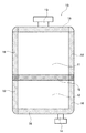
図1は、本発明の複室輸液容器10の一例であって、この複室輸液容器10は、熱可塑性樹脂フィルムから形成され、薬剤が充填される2つの薬剤室11、12を備えたものである。この例の複室輸液容器10においては、一方の薬剤室11には薬剤投入部13が接続され、他方の薬剤室12には、これに薬剤を投入するとともに、薬剤を患者に投与する際にここから薬剤を排出させるための薬剤出入部14が接続されている。
The container of the present invention will be specifically described below.
First, the container of the present invention will be described by taking a multi-chamber infusion container as the container of the present invention as an example.
FIG. 1 shows an example of a
一方、この複室輸液容器10に形成されている2つの薬剤室11、12は、剥離の方向により剥離強度の異なるシール部(単一方向剥離性融着部)15で隔てられている。
この方向により剥離強度の異なるシール部15は、薬剤室11、12にそれぞれ薬剤(充填物)が充填された後、いずれかの区画部に外力を加えることによってシール部15が剥離して、所望の際に薬剤同士を迅速かつ容易に混合できるようになっている。例えば、薬剤室11(第1の区画部11)に充填されている薬剤を、薬剤室12(第2の区画部12)に充填されている薬剤を混入させる場合には、薬剤室11(第1の区画部11)に圧力を加えることによって、隔壁15(シール部15)は貫通するが、薬剤室12(第2の区画部12)に圧力が加えられた場合には、隔壁15(シール部15)に剥離は生じない。即ち、区画部11からの圧力に対しては、シール部15は、易剥離性(弱融着性)であるのに対して、区画部12からの圧力に対しては難剥離性(強融着性)である。
On the other hand, the two
The
この複室輸液容器10の周縁は、薬剤室11、12の外方から力を加えた場合でも剥離しない強シール部16により液密に閉じられていて、熱可塑性樹脂フィルムがヒートシールされ、強く融着して形成されている。なお、この例においては、強シール部16は、複室輸液容器10の周縁の全周にわたって形成されているが、例えば、筒状の熱可塑性樹脂フィルムを材料として使用した場合などには、フィルムの長さ方向の両端部(図中、上端部および下端部)だけが強シール部16となっていてもよく、必ずしも周縁全周に強シール部16が形成されていなくても良い。
The peripheral edge of the
そして、この例の複室輸液容器10の単一方向剥離性熱融着部15には、詳しく後述するが、重ねられた2枚の熱可塑性樹脂フィルムを、シール面に特定のシールエッジが形成された2本(一対)のヒートシールバーで、その両面側から挟持することにより形成されるものであって、図2の拡大平面図にその一部分を示すように、少なくとも融着強度の異なる2つの融着部、すなわち強融着部15aと弱融着部15bとが共存している。
And, as will be described in detail later, in the single-direction peelable heat-sealed
このような強融着部と弱融着部とを有する単一方向剥離性熱融着部15は2本のヒートシールバーに凹凸を形成し、このように凹凸が形成されたヒートシールバーを用いて熱可塑性樹脂フィルムにかかる圧力に差を生じさせて強融着部と弱融着部とを区分してヒートシールすることにより形成することができる。すなわち、シールバーの凹凸が加熱されたフィルムに所定の圧力及び時間で接触することにより、熱可塑性樹脂フィルムが加熱圧着され、この加熱圧着の際に凸部はより強い圧力で熱可塑性樹脂フィルムを相互に密着するため強融着部になり、他方、凹部は圧着力が弱いので熱可塑性樹脂フィルムの密着力が低くなり、弱融着部となる。
The unidirectionally peelable
なお、この図2の態様は、三角形状の隔壁15(シール部15)すなわち強融着部15aが、第1の区画部11側も第2の区画部12側も同じ割合であり、強融着部15aの配置に密と疎の関係がない。よって、この図2の態様は、本発明の実施例ではなく参考例である。
In the embodiment of FIG. 2, the triangular partition 15 (seal part 15), that is, the
シールバーに形成される凹凸に関する形状に特に制限はなく、丸型、四角、菱形のような駒形状を採ることもできるし、単にある幅を持った線で凹凸をつけてもよい。
また、凹凸は上下のヒートシールバーそれぞれに形成しても良いし、どちらか一方だけに形成することも可能である。また、上下のヒートシールバーに、それぞれに凹凸を形成する場合、上下のヒートシールバーにそれぞれ違う形状の凹凸を形成することもできるし、また上下のヒートシールバーに形成された凹凸配置により、強融着部および弱融着部を所望の位置に配置することもできる。
There is no particular limitation on the shape related to the unevenness formed on the seal bar, and a piece shape such as a round shape, a square shape, or a rhombus shape may be adopted, or the unevenness may be provided with a line having a certain width.
Further, the unevenness may be formed on each of the upper and lower heat seal bars, or may be formed on only one of them. In addition, when forming unevenness on the upper and lower heat seal bars, respectively, it is possible to form unevenness of different shapes on the upper and lower heat seal bars, or by the uneven arrangement formed on the upper and lower heat seal bars, It is also possible to arrange the strong fusion part and the weak fusion part at a desired position.
さらに、ヒートシールバーに形成される凸部と凹部との間になだらかな傾斜を設けることも可能である。
当然であるが強融着部と弱融着部との間に中間的な強度を有する融着部ができることもある。
Furthermore, it is possible to provide a gentle slope between the convex portion and the concave portion formed on the heat seal bar.
As a matter of course, a fusion part having intermediate strength may be formed between the strong fusion part and the weak fusion part.
この強融着部と弱融着部との形成比率は、剥離に方向性が発現するように適宜選定することができるが、強融着部の面積が単一方向剥離性熱融着部の全面積に占める割合が、通常は0.01〜70%、好ましくは0.01〜60%、特に好ましくは0.1〜50%の範囲である。強融着部の面積が0.01%より少ないかまたは70%よりも多いと、共にシール強度の制御が難しい。 The formation ratio of the strongly fused portion and the weakly fused portion can be appropriately selected so that directionality is exhibited in peeling, but the area of the strongly fused portion is the same as that of the unidirectional peelable heat fused portion. The proportion of the total area is usually 0.01 to 70%, preferably 0.01 to 60%, particularly preferably 0.1 to 50%. When the area of the strong fusion part is less than 0.01% or more than 70%, it is difficult to control the seal strength.
融着強度に方向性を持たせる手法については、下記の方法を挙げることができる。
1)強融着部の融着強度に幅方向に対しテーパーをつけて非対称とする。すなわち、強融着部を形成するためのヒートシールバーにテーパ面を具備させ、このようにテーパ面を具備したヒートシールバーを使用することにより、強融着部の第2の区画部側の熱可塑性樹脂フィルムの厚さが薄く、第1の区画部側の熱可塑性樹脂フィルムの厚さが厚くなる傾斜部分を形成する。
The method to impart directionality to the fusion strength, can be a method of lower SL.
1) the fusion strength of TsuyoToruchaku parts per width direction shall be the asymmetric tapered. That is, by providing the heat seal bar for forming the strongly fused portion with a tapered surface, and using the heat seal bar having the tapered surface in this way, the second fusion portion side of the strongly fused portion is provided. An inclined portion is formed in which the thickness of the thermoplastic resin film is thin and the thickness of the thermoplastic resin film on the first partition portion side is increased.
さらに、これに加えて、下記の(2)の方法によって形成されていても良い;
(2)該易剥離性シール部に、前記ヒートシール面同士が互いに強度に密着された三角形からなる強融着部を複数個有し、かつ、これら三角形からなる複数個の強融着部は、前記第2の区画部側に頂点を配した態様で形成され、さらに、これら複数個の強融着部は、前記第1の区画部に近い程疎、前記第2の区画部に近い程密となるように、易剥離性シール部の幅方向に対して散在的に配置されている。
In addition to this, it may be formed by the following method (2);
(2) The easily peelable seal portion has a plurality of strong fusion portions made of triangles in which the heat seal surfaces are closely adhered to each other, and the plurality of strong fusion portions made of these triangles are In addition, it is formed in such a manner that apexes are arranged on the second partition part side, and the plurality of strongly fused parts are sparser as they are closer to the first partition part and closer to the second partition part. It arrange | positions disperse | distributed with respect to the width direction of an easily peelable seal part so that it may become dense.
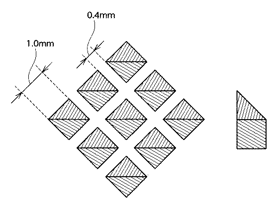
一般に融着部分の形状が三角形の場合に、開封に要する強度は、三角形の底辺側から頂点側に向かうに従って大きくなる。そこで、上記図3に示すように強融着部を三角形とした場合には、図3(a)に示すように、三角形の頂部側から底部側に向かって剥離する際には、難剥離であるのに対して、図3(b)に示すように、三角形の底部から頂部に向かって剥離する際には、易剥離である。 If the shape of the fused portion is triangular in general, strength required for opening increases toward the vertex side from the bottom side of the triangle. Therefore, in the case where the strongly fused portion is triangular as shown in FIG. 3, when peeling from the top side to the bottom side of the triangle, as shown in FIG. On the other hand, as shown in FIG. 3B, when peeling from the bottom of the triangle toward the top, it is easy to peel off.
図4では、強融着部は四角形で表されており、図4の上部では、強融着部が多数形成されているのに対して、下部には強融着部の数が少ない。したがって、図4に剥離方向(a)で示す方向からの剥離は易剥離であるのに対して、図4に剥離方向(b)で示す方向からの剥離は難剥離である。このように、強融着部の分布に差をつけることにより、剥離強度に方向性が生じる。なお、本発明に係る強融着部の形状は、四角形ではなく三角形である。 In FIG. 4, the strong fusion part is represented by a rectangle. In the upper part of FIG. 4, many strong fusion parts are formed, whereas in the lower part, the number of strong fusion parts is small. Therefore, peeling from the direction indicated by the peeling direction (a) in FIG. 4 is easy peeling, whereas peeling from the direction indicated by the peeling direction (b) in FIG. 4 is difficult peeling. In this way, by making a difference in the distribution of the strongly fused portions, directionality occurs in the peel strength. In addition, the shape of the strong melt | fusion part which concerns on this invention is not a square but a triangle.
図5は、上記1)の対応を示す図である。
図5に示すように、強融着部を形成するヒートシールバーの形状にテーパーを設けることにより、圧着強度がシール部の幅方向に対し非対称となり剥離強度に方向性が生じる。強融着部は四角形ではなく、三角形である。
FIG. 5 is a diagram showing the correspondence 1).
As shown in FIG. 5, by providing a taper in the shape of the heat seal bar forming the strongly fused portion, the pressure bonding strength becomes asymmetric with respect to the width direction of the seal portion, and the peel strength is directional. The strongly fused portion is not a quadrangle but a triangle.
なお、図5では、ヒートシールバーの形状を四角形としているが、本発明で適用されるヒートシールバーの形状は三角形である。
なお、図5〜図7の各左図はヒートシール部(ヒートシールバー)を垂直方向(図1の紙面に対して垂直な方向)から拡大して見た図であり、図5〜図7の各右図はそのヒートシール部を形成するためのヒートシールバーを側面から見た図である。上下方向がシール部15の幅方向に相当し、全体の三画形あるいはひし形が強融着部にあたる。
In FIG. 5, the shape of the heat seal bar is a square, but the shape of the heat seal bar applied in the present invention is a triangle .
In addition, each left figure of FIGS. 5-7 is the figure which expanded and looked at the heat seal part (heat seal bar) from the perpendicular | vertical direction (direction perpendicular | vertical with respect to the paper surface of FIG. 1) . Each right figure is a view of a heat seal bar for forming the heat seal portion as viewed from the side. The vertical direction corresponds to the width direction of the
フィルムを上記例示されたような形状のヒートシールバーを用いて、溶着させる場合、上下2本のヒートシールバーの温度設定については特に制限がなく、樹脂が半溶融状態となるように設定すればよい。 When the film is welded using the heat seal bar having the shape exemplified above, the temperature setting of the upper and lower two heat seal bars is not particularly limited, and if the resin is set to be in a semi-molten state. Good.
例えば、上部シールバーと下部シールバーとを均等に温度設定しても良いし、上下に温度差をつけることも可能である。また、シール時間、シール圧力についても使用する樹脂が半溶融状態を保つ範囲で任意の値が使用される。 For example, the temperature of the upper seal bar and the lower seal bar may be set evenly, or a temperature difference may be given up and down. Further, as for the sealing time and the sealing pressure, arbitrary values are used as long as the resin used maintains a semi-molten state.
また、ヒートシールバーの幅方向に温度分布を生じさせることにより、シール部の幅方向の両縁部で融着強度に差を形成することも可能であり、シール部の幅方向において、一方の縁部を強融着部とし、他方の縁部を弱融着部とすることもできる。 In addition, by generating a temperature distribution in the width direction of the heat seal bar, it is also possible to form a difference in the fusion strength at both edges in the width direction of the seal portion. The edge portion can be a strong fusion portion, and the other edge portion can be a weak fusion portion.
本発明の容器において、例えば複室輸液容器の弱シール部の単一方向剥離性熱融着部は、剥離方向により剥離に要する強度に異方性がある。
シール部の幅方向の一方の端部から剥離したときの開封強度をF1、もう一方から剥離したときの開封強度をF2とし、F1<F2の関係が成り立つ、すなわち、開封強度F2がF1よりも大きい時、このF1の剥離強度は初期値で好ましくは1〜6Nmm/15幅、より好ましくは2〜6N/15mm幅である。
In the container of the present invention, for example, the unidirectional peelable heat-sealed part of the weak seal part of the multi-chamber infusion container has anisotropy in the strength required for peeling depending on the peeling direction.
The opening strength when peeled from one end in the width direction of the seal portion is F1, the opening strength when peeled from the other is F2, and the relationship of F1 <F2 holds. That is, the opening strength F2 is higher than F1. When it is large, the peel strength of F1 is preferably 1 to 6 Nmm / 15 width, more preferably 2 to 6 N / 15 mm width as an initial value.
開封強度F1が初期値で1N/15mm幅以上であると、シール強度が適度にあり、わずかな衝撃や応力によって開封してしまうおそれがないため好ましい。また開封強度F1が初期値で6N/15mm幅以下であると、使用時に液を混合するため力を加えることで開封可能となるため好ましい。 It is preferable that the opening strength F1 is 1 N / 15 mm width or more at the initial value because the sealing strength is moderate and there is no fear of opening by a slight impact or stress. Moreover, it is preferable for the opening strength F1 to be 6 N / 15 mm width or less at the initial value, since it can be opened by applying a force to mix the liquid during use.
開封強度F2は、上記開封強度F1よりも高い値であれば良いが、単一方向剥離性の観点からは、F1との差が大きい方が好ましい。F2/F1比率は通常1.05倍〜100倍程度である。 The opening strength F2 may be a value higher than the opening strength F1, but from the viewpoint of unidirectional peelability, a larger difference from F1 is preferable. The F2 / F1 ratio is usually about 1.05 to 100 times.
本発明の容器10を形成するために使用される樹脂フィルムとしては、種々の樹脂フィルムが使用可能であるが、好適には熱可塑性樹脂フィルムが使用される。このような熱可塑性樹脂フィルムとしては、特に制限なく使用できるが、価格、物性(透明性、柔軟性等)のバランスからポリオレフィン系樹脂が好ましい。例えば、熱可塑性樹脂フィルムとしては、高密度ポリエチレン、中密度ポリエチレン、高圧法低密度ポリエチレン、低密度ポリエチレン、直鎖状低密度ポリエチレン、エチレン−酢酸ビニル共重合体等のポリエチレン系樹脂、エチレン−ブテンランダム共重合体等のオレフィン系エラストマー、ポリプロピレン、エチレン−プロピレンランダム共重合体、α−オレフィン−プロピレンランダム共重合体等のポリプロピレン系樹脂およびこれらの混合物などを例示できる。また、本発明の容器が上述のような複室輸液容器10である場合には、上述したように、シール強度に方向性を持たせられれば特定の樹脂を選択して使用する必要は特にないので、熱可塑性樹脂フィルムとして医療の分野で用いられるものであれば特に限定されず使用可能であり、塩化ビニル、エチレン酢酸ビニル共重合体、ポリエーテルサルホン、環状ポリオレフィン、環状ポリオレフィン共重合体、水素化スチレンエチレンブタジエン共重合体などのスチレン系エラストマー、これらの樹脂の混合物、さらにはこれらと上記ポリオレフィン系樹脂との混合物などからなるフィルムも使用できる。また、これらの樹脂は耐熱性向上等の目的で一部架橋されていても構わない。
Various resin films can be used as the resin film used to form the
さらに、使用される熱可塑性樹脂フィルムは、一種類のフィルムからなる単層フィルムであっても、複数の種類のフィルムが積層した形態の多層フィルムであってもよい。熱可塑性樹脂フィルムが単層フィルムである場合には、透明性、柔軟性に優れることから直鎖状低密度ポリエチレン、ポリプロピレン、プロピレンエチレンランダム共重合体、プロピレンエチレンブロック共重合体、プロピレン系樹脂とエチレン系エラストマーとの混合物、プロピレン系樹脂とプロピレン系エラストマーとの混合物、プロピレン系樹脂とスチレン系エラストマーとの混合物などのフィルムが好ましい。熱可塑性樹脂フィルムが多層フィルムである場合には、複室輸液容器の外側から、高密度ポリエチレン/直鎖状低密度ポリエチレン、中密度ポリエチレン/低密度ポリエチレン/高密度ポリエチレン、高密度ポリエチレン/低密度ポリエチレン/高密度ポリエチレンなどのものを例示できる。 Furthermore, the thermoplastic resin film used may be a single-layer film made of one type of film or a multilayer film in which a plurality of types of films are laminated. When the thermoplastic resin film is a single layer film, it is excellent in transparency and flexibility, so that linear low density polyethylene, polypropylene, propylene ethylene random copolymer, propylene ethylene block copolymer, propylene resin and Films such as a mixture of an ethylene elastomer, a mixture of a propylene resin and a propylene elastomer, a mixture of a propylene resin and a styrene elastomer are preferred. When the thermoplastic resin film is a multilayer film, from the outside of the multi-chamber infusion container, high density polyethylene / linear low density polyethylene, medium density polyethylene / low density polyethylene / high density polyethylene, high density polyethylene / low density Examples include polyethylene / high density polyethylene.
また、多層フィルムにおいて、内層がイージーピールを可能にする樹脂組成物から構成されていてもよい。
本発明で使用される熱可塑性フィルムの製造方法については特に限定されず、Tダイ成形、水冷インフレーション成形、空冷インフレーション成形、ブロー成形、ラミネーション成形などによる製造方法が挙げられる。透明性の観点からはTダイ成形、水冷インフレーション成形が好ましい。
Moreover, in a multilayer film, the inner layer may be comprised from the resin composition which enables an easy peel.
The method for producing the thermoplastic film used in the present invention is not particularly limited, and examples thereof include production methods by T-die molding, water-cooled inflation molding, air-cooled inflation molding, blow molding, lamination molding, and the like. From the viewpoint of transparency, T-die molding and water-cooled inflation molding are preferable.
また、本発明で使用される熱可塑性樹脂フィルムの厚さは、通常は5〜1000μm、好ましくは50〜500μm程度である。
上記のような熱可塑性樹脂フィルムから形成される複室輸液容器は、4方向に強シール部が形成され、この強シール部で囲繞された空隙内に単一方向剥離性融着部が形成され、この単一方向剥離性融着部によって区画された区画部1からの剥離強度F1と区画部2からの剥離強度F2とが異なり、一方の区画部に圧力をかけたときに単一方向剥離性融着部が連通して区画部1と区画部2とが連結状態になるが、本発明の容器はこのような態様のほかに、3方向を強シール部として、他の一方を易剥離性シール部とする容器であってもよい。
Moreover, the thickness of the thermoplastic resin film used by this invention is 5-1000 micrometers normally, Preferably it is about 50-500 micrometers.
The multi-chamber infusion container formed from the thermoplastic resin film as described above has a strong seal portion formed in four directions, and a unidirectional peelable fusion portion is formed in the space surrounded by the strong seal portion. The peel strength F1 from the partition section 1 partitioned by the unidirectional peelable fusion section is different from the peel strength F2 from the partition section 2, and the unidirectional stripping occurs when pressure is applied to one partition section. However, the container of the present invention has three directions as strong seal portions and the other one is easily peeled off. It may be a container used as a sealable seal.
また、本発明の複室輸液容器には、小容器を区画部内に収容し、これを区画部の対向する内壁面に熱融着で固定してもよい。
図12(a)には、区画部11内に小容器20が収容された複室輸液容器の例が示されている。また、図12(b)、図12(c)は、図12(a)におけるX−X断面図である。図12において、図1に示す部材と共通の部材には同一の付番が付されている。
Further, in the multi-chamber infusion container of the present invention, a small container may be accommodated in the partition part, and this may be fixed to the inner wall surface facing the partition part by heat fusion.
FIG. 12A shows an example of a multi-chamber infusion container in which the
なお、上記小容器は、区画部11,12のいずれかに圧力を加えてシール部15を剥離させた時、同時に小容器20の易剥離部35(斜線部)も剥離されるようにされている。この方法としては、図12(b)の状態から剥離部15が剥離される時に、図12(b)の矢印Fで示した力により開かれる容器フィルムに引かれて、小容器20の易剥離部35が剥離され、図12(c)の状態とする方法がある。
In addition, when the said small container applies a pressure to either of the
図13(a)において、シール部15は、区画部12からの圧力に対して易剥離性であることが好ましい。このように小容器が収容されていない区画部に圧力を加えるようにすることで、シール部15全体に圧力が加わり、確実に剥離貫通させることができる。
In FIG. 13A, the
また、図12(a)において、小容器20の易剥離部35に単一方向剥離性を付与することが好ましい。このようにすれば、小容器の易剥離部が、目的とする方向に確実に剥離可能となる。例えば、図12(d)の形態の単一方向剥離部を形成すれば、図の下から上方向に剥離が容易であるようにすることができ、小容器の易剥離部35の剥離の確実性が増す。
Moreover, in FIG. 12A, it is preferable to impart unidirectional peelability to the
なお、図12では省略されているが、単一方向剥離部には加圧したときの開封が容易になるように、剥離開始部が形成されていてもよい。
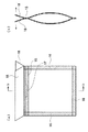
本発明の容器は、上述のように複数の区画部が単一方向剥離性融着部(易剥離性シール部)で区画された形態であることが好ましいが、区画部が1つであってもよい。即ち、図11および図13に示すように、単室容器の開口部を上述のような易剥離性シール部で形成し、この開口部を形成する易剥離性シール部を、開封する側からの剥離が容易になるように単一方向剥離性融着部とすることが好ましい。図11(a)は単室容器の開口部として、易剥離性シール部が形成された容器を示す模式図であり、図11(b)は、a−a断面図であり、一部に易剥離性シールからなる剥離開始部17が形成されており、図11(b)には開封が開始される側に、一部が易剥離シールからなる剥離開始部17が示されている。この剥離開始部17には、上述のように強融着部と弱融着部とが形成されており、この容器の内部からの剥離が容易になる。この容器は、剥離開始部の少し下の樹脂フィルムを持って両方向に引っ張ると、剥離開始部から剥離が開始され、容易にこの容器を開封することができる。しかも、開封開始部が形成されているので、開封開始位置が常にこの剥離開始部であり、常に一定した状態で容器を開封することができる。
Although omitted in FIG. 12, a peeling start portion may be formed on the unidirectional peeling portion so as to facilitate opening when pressurized.
The container of the present invention preferably has a configuration in which a plurality of partition portions are partitioned by a unidirectional peelable fusion portion (easy peelable seal portion) as described above. Also good. That is, as shown in FIG. 11 and FIG. 13, the opening of the single chamber container is formed with the above-described easily peelable seal portion, and the easily peelable seal portion that forms this opening is formed from the side to be opened. It is preferable to use a unidirectional peelable fusion part so that peeling is easy. Fig.11 (a) is a schematic diagram which shows the container in which the easily peelable seal part was formed as an opening part of a single chamber container, FIG.11 (b) is aa sectional drawing, and it is easy for one part. A peeling
また、図13(a)には、容器の外部からの開封が容易になるように、一部が易剥離シールからなる剥離開始部が形成された容器が模式的に示されており、図13(b)はb−b断面図である。この単室容器においては、容器を形成する熱可塑性樹脂フィルムが、シール部から外側に長く延設されており、この容器を開封する際には、この延設された熱可塑性樹脂フィルム18を持って外側に引っ張ることにより、剥離開始部17から剥離して、この容器を開封することができる。
FIG. 13 (a) schematically shows a container in which a peeling start portion, part of which is an easily peelable seal, is formed so that the container can be easily opened from the outside. (B) is bb sectional drawing. In this single-chamber container, the thermoplastic resin film forming the container is extended to the outside from the seal portion, and when the container is opened, the extended
上記ように一部に易剥離性シールからなる剥離開始部17を形成する場合には、この剥離開始部17を中心にして外側に向かって剥離強度を高くすることが好ましい。さらに、剥離開始部17からシール部の深さ方向に向かって剥離強度を高くすることが好ましい。すなわち、このような剥離開始部17を形成する場合には、この剥離開始部17の剥離強度を最も低く制御することにより、常にこの剥離開始部17から容器の開封を行うことができる。
When forming the peeling
このような剥離開始部17は、上述の単一方向剥離性熱融着部を有する複室輸液バックのような容器の単一方向剥離性融着部においても同様に形成することができるのは勿論である。
次に本発明の容器について説明する。
Such a peeling
Then attached to the container of the present invention to explain.
[参考例1]
水冷インフレーション法で、直鎖状低密度ポリエチレン(MFR=2g/10min(190℃)、密度920kg/m3)からなる厚さ300μmのフィルムを作成した。
このフィルムを2枚重ね、2本のヒートシールバーでこれを挟持することにより、剥離強度に異方性を持つシール部を作成した。
[ Reference Example 1]
A 300 μm-thick film made of linear low-density polyethylene (MFR = 2 g / 10 min (190 ° C.), density 920 kg / m 3 ) was prepared by a water-cooled inflation method.
Two films were stacked and sandwiched between two heat seal bars to create a seal portion having anisotropy in peel strength.
なお、剥離強度に異方性を持つシール部(単一方向剥離性融着部)は、複室輸液容器10の長さ方向の中央部に10mm長さで形成した。また、この際に使用した2本のヒートシールバーの内、上のバーは図6の具体例に示した三角形状の強融着部を有するバーを使用し、下のバーはフラットなバーを使用した。シール圧力0.3MPa、シール時間3.4秒の条件でヒートシールを行った。
In addition, the seal | sticker part (single direction peelable fusion | fusion part) which has anisotropy in peeling strength was formed in the center part of the length direction of the
この図6の具体例を使用して作成したシール部の剥離強度を両側から測定したときのシール強度を表1に示す。
なおシール強度はASTM F88に準拠して測定を行った。具体的にはヒートシールバーにて融着した部位を含むフィルムを15mm幅に切り出し、引っ張り試験機の冶具にシールしていない部位を挟み込む。200mm/分の速度で上側に引っ張り融着部が剥離したときの力をシール強度とした。結果を表1および図8に示す。
Seal strength when the peel strength was measured from both sides of the seal portion created using the embodiment of FIG. 6 of this are shown in Table 1.
The seal strength was measured according to ASTM F88. Specifically, a film including a part fused by a heat seal bar is cut out to a width of 15 mm, and a part not sealed is sandwiched between jigs of a tensile tester. The force at the time of pulling upward at a speed of 200 mm / min and peeling off the fused part was defined as the seal strength. The results are shown in Table 1 and FIG.
[参考例2]
参考例2において、図5に示したシールバーを使用した他は、実施例1と同様にしてシールを行い剥離強度の異方性を測定した結果を表2および図9に示す。
[Reference Example 2]
Table 2 and FIG. 9 show the results of sealing and measuring the anisotropy of peel strength in the same manner as in Example 1 except that the seal bar shown in FIG. 5 was used in Reference Example 2 .
〔比較例1〕
参考例1で使用したヒートシールバーの代わりに、図7に示す様な菱形形状のシールバーを用いて参考例1と同様にしてシールを行い剥離強度の異方性を測定した。結果を表3および図10に示す。バー形状、配列が対称な場合は、剥離強度に異方性を持たせることが出来なかった。
[Comparative Example 1]
Instead of the heat seal bar used in Reference Example 1, a rhombus-shaped seal bar as shown in FIG. 7 was used for sealing in the same manner as in Reference Example 1, and the anisotropy of peel strength was measured. The results are shown in Table 3 and FIG. When the bar shape and arrangement were symmetrical, the peel strength could not be made anisotropic.
10・・・容器
11・・・薬剤室(第1の区画部)
12・・・薬剤室(第2の区画部)
13・・・薬剤投入部
14・・・薬剤出入部
15・・・シール部(単一方向剥離性融着部)
15a・・強融着部
15b・・弱融着部
16・・・強シール部
17・・・剥離開始部
18・・・延設された熱可塑性樹脂フィルム
20・・・第3の区画部
35・・・易剥離部
10 ...
12 ... Drug room (second compartment)
13 ...
15a .. Strongly fused
Claims (1)
前記易剥離性シール部は、前記第1の区画部に近い程融着強度が小さく、前記第2の区画部に近い程融着強度が大きくなるように、その融着強度に方向性を有するものであり、前記易剥離性シール部が下記の(1)および(2)によって形成されていることを特徴とする容器;
(1)該易剥離性シール部に形成された強融着部は、該強融着部を形成するためのヒートシールバーにテーパ面が具備されることにより、ヒートシールされた強融着部の前記第2の区画部側の熱可塑性樹脂フィルムの厚さが薄く、前記第1の区画部側の熱可塑性樹脂フィルムの厚さが厚くなる傾斜部分が形成されている。
(2)該易剥離性シール部に、前記ヒートシール面同士が互いに強度に密着された三角形からなる強融着部を複数個有し、かつ、これら三角形からなる複数個の強融着部は、前記第2の区画部側に頂点を配した態様で形成され、さらに、これら複数個の強融着部は、前記第1の区画部に近い程疎、前記第2の区画部に近い程密となるように、易剥離性シール部の幅方向に対して散在的に配置されている。 A thermoplastic resin film arranged so that the heat seal surfaces face each other is fused to form a strong seal part around it, and the void surrounded by the strong seal part is liquid-tight and easy to peel off A container defined by a seal section into a first partition section and a second partition section;
The easily peelable seal portion has directionality in the fusion strength so that the fusion strength is smaller as it is closer to the first partition portion and the fusion strength is larger as it is closer to the second partition portion. A container wherein the easily peelable seal portion is formed by the following (1) and (2) ;
(1) The strong fusion part formed in the easily peelable seal part is a heat-sealed strong fusion part provided with a tapered surface on a heat seal bar for forming the strong fusion part. The thickness of the thermoplastic resin film on the second partition portion side is small, and an inclined portion is formed where the thickness of the thermoplastic resin film on the first partition portion side is large.
(2) The easily peelable seal portion has a plurality of strong fusion portions made of triangles in which the heat seal surfaces are closely adhered to each other, and the plurality of strong fusion portions made of these triangles are In addition, it is formed in such a manner that apexes are arranged on the second partition part side, and the plurality of strongly fused parts are sparser as they are closer to the first partition part and closer to the second partition part. It arrange | positions disperse | distributed with respect to the width direction of an easily peelable seal part so that it may become dense.
Priority Applications (1)
| Application Number | Priority Date | Filing Date | Title |
|---|---|---|---|
| JP2005214087A JP4902149B2 (en) | 2005-07-25 | 2005-07-25 | container |
Applications Claiming Priority (1)
| Application Number | Priority Date | Filing Date | Title |
|---|---|---|---|
| JP2005214087A JP4902149B2 (en) | 2005-07-25 | 2005-07-25 | container |
Publications (2)
| Publication Number | Publication Date |
|---|---|
| JP2007030901A JP2007030901A (en) | 2007-02-08 |
| JP4902149B2 true JP4902149B2 (en) | 2012-03-21 |
Family
ID=37790631
Family Applications (1)
| Application Number | Title | Priority Date | Filing Date |
|---|---|---|---|
| JP2005214087A Expired - Fee Related JP4902149B2 (en) | 2005-07-25 | 2005-07-25 | container |
Country Status (1)
| Country | Link |
|---|---|
| JP (1) | JP4902149B2 (en) |
Families Citing this family (3)
| Publication number | Priority date | Publication date | Assignee | Title |
|---|---|---|---|---|
| JP6494761B2 (en) * | 2015-07-24 | 2019-04-03 | 富士フイルム株式会社 | Release film and adhesive laminate |
| WO2017126068A1 (en) * | 2016-01-21 | 2017-07-27 | 株式会社サンエー化研 | Heating pouch |
| CN117412853A (en) | 2021-06-15 | 2024-01-16 | 户谷技研工业株式会社 | Bag making machine, bag making method and bag |
Family Cites Families (3)
| Publication number | Priority date | Publication date | Assignee | Title |
|---|---|---|---|---|
| JPH0717568A (en) * | 1993-06-30 | 1995-01-20 | Mitsubishi Plastics Ind Ltd | Sealed container and its manufacture |
| JP4366772B2 (en) * | 1999-08-26 | 2009-11-18 | 東洋製罐株式会社 | Packaging for microwave oven |
| JP3095747B1 (en) * | 1999-09-27 | 2000-10-10 | 株式会社ムサシノキカイ | Multiple liquid storage bags |
-
2005
- 2005-07-25 JP JP2005214087A patent/JP4902149B2/en not_active Expired - Fee Related
Also Published As
| Publication number | Publication date |
|---|---|
| JP2007030901A (en) | 2007-02-08 |
Similar Documents
| Publication | Publication Date | Title |
|---|---|---|
| US20070080078A1 (en) | Plastic container with rupturable seal | |
| JP2001522655A (en) | Flexible multi-compartment medical container with preferential tear seal | |
| TWI252203B (en) | Infusion container with multiple chambers and production method thereof | |
| JP5557004B2 (en) | Medical container | |
| JP4749057B2 (en) | Multi-chamber infusion container and manufacturing method thereof | |
| JP4902149B2 (en) | container | |
| JP4298308B2 (en) | Multi-chamber infusion container and manufacturing method thereof | |
| ES2212282T3 (en) | POLYMER FILMS AND PACKAGES PRODUCED FROM THE SAME. | |
| JP2003062038A (en) | Chemical container with inner small bag for chemical solution | |
| JP6106891B2 (en) | Multilayer film, chemical container, and method for producing the same | |
| JP2000007050A (en) | Multi-room container | |
| JP2006526552A (en) | Plastic container with breakable seal | |
| JP4613037B2 (en) | Polypropylene resin multi-chamber bag | |
| JP4689416B2 (en) | Multi-chamber container | |
| JP2006263375A (en) | Container with double chambers for medical use | |
| JP4644480B2 (en) | Polyolefin resin multi-chamber bag | |
| JP6478400B2 (en) | Bag-shaped container, medical multi-chamber container, mold and method of forming curvilinear belt-like weak seal | |
| JP4962733B2 (en) | Multi-chamber container | |
| JP2017007696A (en) | Packaging bag | |
| JPH0639018A (en) | Container for medial treatment | |
| JP4695866B2 (en) | Plastic multi-chamber bag with small bag | |
| WO2017131109A1 (en) | Multi-chambered container | |
| JP4365948B2 (en) | Infusion bag | |
| JPH10201819A (en) | Double cell container for medical treatment | |
| JP4962734B2 (en) | Multi-chamber container |
Legal Events
| Date | Code | Title | Description |
|---|---|---|---|
| A621 | Written request for application examination |
Free format text: JAPANESE INTERMEDIATE CODE: A621 Effective date: 20070907 |
|
| A977 | Report on retrieval |
Free format text: JAPANESE INTERMEDIATE CODE: A971007 Effective date: 20100326 |
|
| A131 | Notification of reasons for refusal |
Free format text: JAPANESE INTERMEDIATE CODE: A131 Effective date: 20100615 |
|
| A521 | Request for written amendment filed |
Free format text: JAPANESE INTERMEDIATE CODE: A523 Effective date: 20100806 |
|
| A02 | Decision of refusal |
Free format text: JAPANESE INTERMEDIATE CODE: A02 Effective date: 20101102 |
|
| A521 | Request for written amendment filed |
Free format text: JAPANESE INTERMEDIATE CODE: A523 Effective date: 20110202 |
|
| A911 | Transfer to examiner for re-examination before appeal (zenchi) |
Free format text: JAPANESE INTERMEDIATE CODE: A911 Effective date: 20110210 |
|
| A912 | Re-examination (zenchi) completed and case transferred to appeal board |
Free format text: JAPANESE INTERMEDIATE CODE: A912 Effective date: 20110304 |
|
| A521 | Request for written amendment filed |
Free format text: JAPANESE INTERMEDIATE CODE: A523 Effective date: 20111104 |
|
| A01 | Written decision to grant a patent or to grant a registration (utility model) |
Free format text: JAPANESE INTERMEDIATE CODE: A01 |
|
| A61 | First payment of annual fees (during grant procedure) |
Free format text: JAPANESE INTERMEDIATE CODE: A61 Effective date: 20111228 |
|
| R150 | Certificate of patent or registration of utility model |
Ref document number: 4902149 Country of ref document: JP Free format text: JAPANESE INTERMEDIATE CODE: R150 Free format text: JAPANESE INTERMEDIATE CODE: R150 |
|
| FPAY | Renewal fee payment (event date is renewal date of database) |
Free format text: PAYMENT UNTIL: 20150113 Year of fee payment: 3 |
|
| R250 | Receipt of annual fees |
Free format text: JAPANESE INTERMEDIATE CODE: R250 |
|
| R250 | Receipt of annual fees |
Free format text: JAPANESE INTERMEDIATE CODE: R250 |
|
| R250 | Receipt of annual fees |
Free format text: JAPANESE INTERMEDIATE CODE: R250 |
|
| R250 | Receipt of annual fees |
Free format text: JAPANESE INTERMEDIATE CODE: R250 |
|
| R250 | Receipt of annual fees |
Free format text: JAPANESE INTERMEDIATE CODE: R250 |
|
| R250 | Receipt of annual fees |
Free format text: JAPANESE INTERMEDIATE CODE: R250 |
|
| R250 | Receipt of annual fees |
Free format text: JAPANESE INTERMEDIATE CODE: R250 |
|
| R250 | Receipt of annual fees |
Free format text: JAPANESE INTERMEDIATE CODE: R250 |
|
| LAPS | Cancellation because of no payment of annual fees |