JP4899997B2 - Thermal siphon boiling cooler - Google Patents
Thermal siphon boiling cooler Download PDFInfo
- Publication number
- JP4899997B2 JP4899997B2 JP2007094565A JP2007094565A JP4899997B2 JP 4899997 B2 JP4899997 B2 JP 4899997B2 JP 2007094565 A JP2007094565 A JP 2007094565A JP 2007094565 A JP2007094565 A JP 2007094565A JP 4899997 B2 JP4899997 B2 JP 4899997B2
- Authority
- JP
- Japan
- Prior art keywords
- refrigerant
- heat
- flow path
- boiling
- heat absorption
- Prior art date
- Legal status (The legal status is an assumption and is not a legal conclusion. Google has not performed a legal analysis and makes no representation as to the accuracy of the status listed.)
- Active
Links
Images


Classifications
-
- F—MECHANICAL ENGINEERING; LIGHTING; HEATING; WEAPONS; BLASTING
- F28—HEAT EXCHANGE IN GENERAL
- F28D—HEAT-EXCHANGE APPARATUS, NOT PROVIDED FOR IN ANOTHER SUBCLASS, IN WHICH THE HEAT-EXCHANGE MEDIA DO NOT COME INTO DIRECT CONTACT
- F28D15/00—Heat-exchange apparatus with the intermediate heat-transfer medium in closed tubes passing into or through the conduit walls ; Heat-exchange apparatus employing intermediate heat-transfer medium or bodies
- F28D15/02—Heat-exchange apparatus with the intermediate heat-transfer medium in closed tubes passing into or through the conduit walls ; Heat-exchange apparatus employing intermediate heat-transfer medium or bodies in which the medium condenses and evaporates, e.g. heat pipes
- F28D15/0266—Heat-exchange apparatus with the intermediate heat-transfer medium in closed tubes passing into or through the conduit walls ; Heat-exchange apparatus employing intermediate heat-transfer medium or bodies in which the medium condenses and evaporates, e.g. heat pipes with separate evaporating and condensing chambers connected by at least one conduit; Loop-type heat pipes; with multiple or common evaporating or condensing chambers
-
- H—ELECTRICITY
- H01—ELECTRIC ELEMENTS
- H01L—SEMICONDUCTOR DEVICES NOT COVERED BY CLASS H10
- H01L2924/00—Indexing scheme for arrangements or methods for connecting or disconnecting semiconductor or solid-state bodies as covered by H01L24/00
- H01L2924/0001—Technical content checked by a classifier
- H01L2924/0002—Not covered by any one of groups H01L24/00, H01L24/00 and H01L2224/00
Landscapes
- Engineering & Computer Science (AREA)
- Life Sciences & Earth Sciences (AREA)
- Sustainable Development (AREA)
- Physics & Mathematics (AREA)
- Thermal Sciences (AREA)
- Mechanical Engineering (AREA)
- General Engineering & Computer Science (AREA)
- Cooling Or The Like Of Semiconductors Or Solid State Devices (AREA)
- Cooling Or The Like Of Electrical Apparatus (AREA)
Description
本発明は、半導体装置及び電子機器等の冷却器に関し、特に、沸騰現象を利用して冷媒を循環させるサーマルサイフォン式沸騰冷却器に関する。 The present invention relates to a cooler for semiconductor devices, electronic devices, and the like, and more particularly to a thermal siphon-type boiling cooler that circulates a refrigerant using a boiling phenomenon.
近年、半導体装置及び電子機器等で発生する大量の熱を冷却するために、半導体装置等の外部に高い熱伝導率を持つ材料を接着し、吸熱器としてその内部に冷媒を流すことにより、高い冷却性能を得ようとする方法が開発されている。また、吸熱器で冷媒を沸騰させることで、より高い冷却効果を得ようとする方法も開発されている。これらの冷却方法においては、冷媒が奪った熱を外部に放出するために冷媒を吸熱部と放熱部との間で循環させる必要があるが、この循環手段として一般的にはポンプが用いられている。 In recent years, in order to cool a large amount of heat generated in semiconductor devices, electronic devices, etc., a material having high thermal conductivity is bonded to the outside of the semiconductor device, etc. Methods have been developed to obtain cooling performance. In addition, a method for obtaining a higher cooling effect by boiling the refrigerant with a heat absorber has been developed. In these cooling methods, it is necessary to circulate the refrigerant between the heat absorbing portion and the heat radiating portion in order to release the heat taken away by the refrigerant to the outside, and a pump is generally used as the circulating means. Yes.
沸騰冷却器の場合、冷媒が沸騰することにより発生する蒸気と液体との密度差により、蒸気が重力方向に対して上側に集まる。この原理を利用して、冷却器下部に吸熱部、及び上部に放熱部を設置することで、ポンプを必要としない、サーマルサイフォン式の冷却構造も提案されている。例えば特許文献1及び特許文献2に開示されている構造がこれにあたる。その他にも、以下に示すような種々の沸騰冷却器が提案されている。なお、以下特に断りのない限り、「沸騰冷却器」又は「サイフォン式の沸騰冷却器」はサーマルサイフォン式の沸騰冷却器をさす。
In the case of a boiling cooler, the vapor collects on the upper side with respect to the direction of gravity due to the density difference between the vapor and the liquid generated by boiling the refrigerant. By utilizing this principle, a thermal siphon type cooling structure that does not require a pump has been proposed by installing a heat absorption part at the lower part of the cooler and a heat radiation part at the upper part. For example, the structures disclosed in Patent Document 1 and
特許文献1では、車両に搭載された電子機器の冷却のためのサイフォン式沸騰冷却器が提案されている。この沸騰冷却器においては、ポンプを必要としない他に、吸熱部及び放熱部を比較的一体として形成することが出来ることを特徴としている。 Patent Document 1 proposes a siphon-type boiling cooler for cooling an electronic device mounted on a vehicle. This boiling cooler is characterized in that, in addition to not requiring a pump, the heat absorption part and the heat radiation part can be formed relatively integrally.
特許文献2では、吸熱部及び放熱部を離れた位置に設置しながらも、重力方向の上側に放熱部、下側に吸熱部を配することで、サイフォン式及びポンプレスの沸騰冷却器が提案されている。この沸騰冷却器においては、吸熱部及び放熱部は以下に示す蒸気管及び液用の管で接続されていることを特徴としている。即ち、吸熱部から放熱部に向かう方には太い蒸気管が用いられ、放熱部の上部に接続されている。また、放熱部から吸熱部に向かう方には細い液用の管が用いられ、放熱部下部に接続されている。なお、重力方向の上部に放熱部、下部に吸熱部を配する構造は、特許文献3にも提案されている。
特許文献4では、ノート型PCのスクリーン側での放熱部において、サイフォン式で冷媒の対流を促す構造が提案されている。この構造において、吸熱部から放熱部までは、ヒートパイプを用いることで、ノート型PCのヒンジ部を熱的に接続しつつ可動性を保つこととしている。
特許文献5では、放熱用ラジエータを吸熱部の極上方に構築することで、吸熱部で発生する蒸気を冷却及び凝縮した後、吸熱部に戻す構造が提案されている。この構造は、吸熱部に「ピラミッド型フィン」を形成することにより、強制対流を利用しないプール沸騰式の冷却装置において沸騰を促進させ、伝熱性能を最適化しようとするものである。 Patent Document 5 proposes a structure in which a radiator for radiating heat is constructed at a position extremely above a heat absorbing portion, whereby steam generated in the heat absorbing portion is cooled and condensed and then returned to the heat absorbing portion. This structure is intended to optimize the heat transfer performance by forming a “pyramid fin” in the heat absorption part to promote boiling in a pool boiling type cooling device that does not use forced convection.
特許文献6では、吸熱部と放熱部をパイプで接続し、冷媒の循環を促すためにヒーターで冷媒を気化させその蒸気圧を利用することにより、冷媒を押し流す熱パルスを利用した方法が提案されている。 Patent Document 6 proposes a method that uses a heat pulse that pushes the refrigerant by connecting the heat absorbing part and the heat radiating part with a pipe, vaporizing the refrigerant with a heater and using the vapor pressure to promote circulation of the refrigerant. ing.
しかしながら、上述した従来の沸騰冷却器には、以下に示すような問題点がある。サイフォン式の沸騰冷却器に用いられる冷媒は、吸熱部に液相として流入し、吸熱部において熱交換により沸騰(気化)した後、蒸気となって放熱部へ向かう。この沸騰の際に、吸熱部の伝熱面に発生した蒸気泡が付着・滞留する。蒸気泡は、冷媒に比べて伝熱効果が小さいため、伝熱面に滞留することにより、沸騰冷却器の冷却性能を低下させる原因となる。例えば、特許文献1乃至5の従来の沸騰冷却器においては、冷媒の循環は吸熱部と放熱部との高さの差という重力効果に依存しており、蒸気泡の滞留を防ぐような構造が示されていない。このため、冷却性能が十分に得られない可能性がある。 However, the conventional boiling cooler described above has the following problems. The refrigerant used in the siphon-type boiling cooler flows into the heat absorption part as a liquid phase, and after boiling (vaporization) by heat exchange in the heat absorption part, it becomes steam and travels to the heat dissipation part. During this boiling, the vapor bubbles generated on the heat transfer surface of the heat absorbing part adhere and stay. Since the vapor bubbles have a smaller heat transfer effect than the refrigerant, they stay on the heat transfer surface and cause the cooling performance of the boiling cooler to deteriorate. For example, in the conventional boiling coolers disclosed in Patent Documents 1 to 5, the circulation of the refrigerant depends on the gravitational effect of the difference in height between the heat absorbing portion and the heat radiating portion, and a structure that prevents the retention of vapor bubbles. Not shown. For this reason, there is a possibility that sufficient cooling performance cannot be obtained.
これに対して、例えばポンプのような外部装置を用いて冷媒を循環・対流させることにより、蒸気泡を剥離させて冷却効果の低下を防ぐことができる。このような、いわゆる強制対流効果は、特許文献6に示す沸騰冷却器において、ヒータで気化させた冷媒の蒸気圧により冷媒を循環させることに相当する。しかしながら、熱力学第2法則の観点からすると、熱を利用して動力を得ようとするこの方法は、ヒータに対して電力が既に供給されていることを考えると、非常に非効率的であると言わざるを得ない。更に、熱パルス発生のための電気回路及び圧力を維持するためのチェックバルブ等が必要であることから、従来型のポンプを使用する方法と比較しても高価なシステムとなってしまうという問題点がある。 On the other hand, for example, by circulating and convection of the refrigerant using an external device such as a pump, it is possible to peel the vapor bubbles and prevent the cooling effect from decreasing. Such a so-called forced convection effect corresponds to circulating the refrigerant by the vapor pressure of the refrigerant vaporized by the heater in the boiling cooler shown in Patent Document 6. However, from the viewpoint of the second law of thermodynamics, this method of obtaining power using heat is very inefficient considering that power is already supplied to the heater. I must say. Furthermore, since an electric circuit for generating heat pulses and a check valve for maintaining pressure are necessary, the system becomes expensive even when compared with a method using a conventional pump. There is.
この他にも、従来の沸騰冷却器においては、上述した重力効果に依存しているため、吸熱部と発熱部との位置関係が、沸騰冷却器が搭載されている機器の使用状態(例えば、「横置き」及び「縦置き」)により変わると十分な冷却性能が得られないという問題点がある。更に、例えば特許文献4の従来の沸騰冷却器においては、吸熱部からヒートパイプ、ヒートパイプから放熱部へとの熱抵抗がかさむ恐れがある。このため、放熱部の気液相の温度は冷却部品の温度と大きな温度差を生じる可能性があり、その結果、沸騰の効果を理想的なまでには実現できないという問題点もある。
In addition to this, in the conventional boiling cooler, because it depends on the above-described gravity effect, the positional relationship between the heat absorption part and the heat generation part is the use state of the equipment in which the boiling cooler is mounted (for example, There is a problem that sufficient cooling performance cannot be obtained if it is changed depending on “horizontal placement” and “vertical placement”. Further, for example, in the conventional boiling cooler disclosed in
本発明はかかる問題点に鑑みてなされたものであって、ポンプ等の外部装置を必要とすることなく、冷却性能を向上させ、吸熱部と放熱部との位置関係が相互に変化する2態様において十分な冷却性能が得られるサーマルサイフォン式沸騰冷却器を提供することを目的とする。 The present invention has been made in view of such problems, and improves the cooling performance without requiring an external device such as a pump, and the two modes in which the positional relationship between the heat absorbing portion and the heat radiating portion changes mutually. It is an object of the present invention to provide a thermal siphon-type boiling cooler that can provide sufficient cooling performance.
本発明に係るサーマルサイフォン式沸騰冷却器は、内部に冷媒流路を備え前記冷媒の気化熱を利用して発熱体を冷却する吸熱部と、気相の冷媒を放熱させる放熱部と、この放熱部と前記吸熱部との間に設けられた蒸気管及び液管と、を有し、前記冷媒流路は、前記冷媒の上流側から下流側に向かって各流路の断面積が増加する複数の第1の流路を含むことを特徴とする。 The thermal siphon type boiling cooler according to the present invention includes a refrigerant flow path inside, a heat absorption part that cools the heating element using the heat of vaporization of the refrigerant, a heat radiation part that radiates heat of the gas-phase refrigerant, and this heat radiation. A steam pipe and a liquid pipe provided between the heat sink and the heat absorption part, and the refrigerant flow path includes a plurality of cross-sectional areas that increase from the upstream side to the downstream side of the refrigerant. The first flow path is included.
本発明においては、冷媒の上流側から下流側に向かって各流路の断面積が増加する複数の第1の流路を設けることにより、第1の流路の下流側が上流側に比べて低い圧力に保たれる。これにより、熱交換により気化した冷媒(蒸気)は圧力差によって下流側に吸い込まれるため、蒸気を効果的に吸熱部から排出することができる。また、複数の第1の流路を設けることにより、流路と冷媒との伝熱面積を大きくすることができる。このため、沸騰冷却器の冷却性能を向上させることができる。 In the present invention, by providing a plurality of first channels whose cross-sectional areas increase from the upstream side to the downstream side of the refrigerant, the downstream side of the first channel is lower than the upstream side. Kept in pressure. Thereby, since the refrigerant | coolant (steam) vaporized by heat exchange is suck | inhaled downstream by a pressure difference, a vapor | steam can be discharged | emitted from a heat absorption part effectively. Further, by providing a plurality of first flow paths, the heat transfer area between the flow paths and the refrigerant can be increased. For this reason, the cooling performance of the boiling cooler can be improved.
この場合に、前記第1の流路は、各流路が前記冷媒の上流側から見て短い方の辺の長さが1mm以下の矩形の断面形状を有していることが好ましい。これにより、第1の流路には液相の冷媒より気相の冷媒の方が流れやすくなるため、蒸気の排出をより促進することができる。また、第1の流路内における流速が大きくなるため、強制対流効果により沸騰により発生する冷媒の蒸気泡を発生直後に流路の内壁から剥離させることができる。このため、伝熱効果の低い蒸気泡の滞留による冷却性能の低下を効果的に抑制することができる。 In this case, it is preferable that the first channel has a rectangular cross-sectional shape in which each channel has a shorter side length of 1 mm or less when viewed from the upstream side of the refrigerant. This makes it easier for the gas-phase refrigerant to flow through the first flow path than the liquid-phase refrigerant, thereby further promoting the discharge of the vapor. Further, since the flow velocity in the first flow path is increased, the vapor bubbles of the refrigerant generated by boiling due to the forced convection effect can be separated from the inner wall of the flow path immediately after the generation. For this reason, the fall of the cooling performance by retention of the vapor bubble with a low heat-transfer effect can be suppressed effectively.
また、前記冷媒流路は、更に前記第1の流路と並列な第2の流路を含み、前記冷媒の上流側から見て前記第1の流路と前記第2の流路とが前記第1の流路を歯として接続されている櫛状の断面形状を有するように構成することができる。これにより、第2の流路に液相の冷媒が流れ、沸騰により蒸気となった冷媒は第1の流路に吸い込まれるので、液相/気相の分離をより促進することができる。 The refrigerant flow path further includes a second flow path in parallel with the first flow path, and the first flow path and the second flow path are viewed from the upstream side of the refrigerant. The first channel can be configured to have a comb-like cross-sectional shape connected as teeth. As a result, the liquid phase refrigerant flows through the second flow path, and the refrigerant that has become vapor due to boiling is sucked into the first flow path, so that the liquid phase / gas phase separation can be further promoted.
上記の第2の流路を有する場合において、前記第2の流路は、少なくとも前記発熱体の熱が伝達される側の面の面積が前記発熱体と前記吸熱部とが接する面の面積より大きく、前記冷媒の上流側から見て短い方の辺の長さが2mm以下の矩形の断面形状を有することが好ましい。これにより、第2の流路における液相の冷媒の流速が大きくなるため、強制対流効果をよる蒸気泡の剥離をより促進することができる。 In the case where the second flow path is provided, the second flow path has at least an area of a surface on the side where heat of the heating element is transmitted is larger than an area of a surface where the heating element and the heat absorbing portion are in contact with each other. It is preferable to have a rectangular cross-sectional shape that is large and has a shorter side length of 2 mm or less when viewed from the upstream side of the refrigerant. Thereby, since the flow rate of the liquid-phase refrigerant in the second flow path is increased, it is possible to further promote the separation of the vapor bubbles due to the forced convection effect.
更に、前記吸熱部、前記蒸気管、前記放熱部及び前記液管の順に閉ループの管路を構成し、冷媒を循環させる外部装置を有しないように構成することができる。この場合においても、上記の強制対流効果により蒸気泡の剥離が促進されるため、冷却効果の低下を効果的に抑制することができる。また、これによりポンプ等の外部装置を必要としないため、コストを低下させることができ、更に、沸騰冷却器の信頼性を向上させることもできる。 Furthermore, it is possible to configure a closed-loop pipeline in the order of the heat absorption part, the steam pipe, the heat radiation part, and the liquid pipe so that there is no external device for circulating the refrigerant. Even in this case, since the peeling of the vapor bubbles is promoted by the forced convection effect, it is possible to effectively suppress the decrease in the cooling effect. Further, this eliminates the need for an external device such as a pump, thereby reducing the cost and further improving the reliability of the boiling cooler.
更にまた、pを前記吸熱部における前記冷媒の圧力損失、ρを前記冷媒の液密度、gを重力加速度とするとき、使用態様における前記放熱部の冷媒出口の位置は、前記吸熱部の冷媒入口の位置よりも重力方向で下記数式(h1=p/(ρ・g))を満たす距離h以上高く、前記吸熱部の冷媒入口の位置と水平方向で距離h以上の距離を有するように構成することができる。これにより、例えば横置きと縦置きのような90度回転させた2つの使用態様の夫々において、沸騰冷却器の内部における冷媒の循環を適切に保つことができ、十分な冷却性能を得ることができる。 Furthermore, when p is the pressure loss of the refrigerant in the heat absorbing part, ρ is the liquid density of the refrigerant, and g is the gravitational acceleration, the position of the refrigerant outlet of the heat radiating part in the usage mode is the refrigerant inlet of the heat absorbing part. It is configured to be higher than the position h by a distance h that satisfies the following mathematical formula (h1 = p / (ρ · g)) in the direction of gravity and at least a distance h in the horizontal direction with respect to the position of the refrigerant inlet of the heat absorption part. be able to. Thus, for example, in each of the two usage modes rotated 90 degrees such as horizontally and vertically, the circulation of the refrigerant in the boiling cooler can be appropriately maintained, and sufficient cooling performance can be obtained. it can.
更にまた、前記冷媒は、表面張力が水よりも小さい液体であるように構成することができる。 Furthermore, the refrigerant can be configured to be a liquid having a surface tension smaller than that of water.
本発明によれば、ポンプ等の外部装置を必要とすることなく、冷却性能を向上させ、吸熱部と放熱部との位置関係が相互に変化する2態様において十分な冷却性能が得られるサーマルサイフォン式沸騰冷却器が得られる。 According to the present invention, a thermal siphon that improves cooling performance without requiring an external device such as a pump, and can provide sufficient cooling performance in two modes in which the positional relationship between the heat absorbing portion and the heat radiating portion changes mutually. A type boiling condenser is obtained.
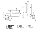
以下、本発明の実施形態について添付の図面を参照して具体的に説明する。先ず、本発明の第1の実施形態について説明する。図1(a)及び(b)は、本第1実施形態に係るサーマルサイフォン式沸騰冷却器の構成を示す図であり、図2(a)乃至(c)は、沸騰式吸熱部を示す断面図である。 Hereinafter, embodiments of the present invention will be specifically described with reference to the accompanying drawings. First, a first embodiment of the present invention will be described. FIGS. 1A and 1B are diagrams showing a configuration of a thermal siphon-type boiling cooler according to the first embodiment, and FIGS. 2A to 2C are cross-sectional views showing a boiling-type heat absorption part. FIG.
図1(a)に示すように、発熱体3に接するように沸騰式吸熱部1が設けられている。この沸騰式吸熱部1の右上部には、放熱部2が配置されている。沸騰式吸熱部1の液流入口9と放熱部2の液流出口11とは液用管5で接続されている。また、沸騰式吸熱部1の蒸気出口10と放熱部2の蒸気入口12とは蒸気用管4で接続されている。これらの沸騰式吸熱部1、蒸気用管4、放熱部2及び液用管5は閉管路を構成しており、その内部には冷媒(図示せず)を有している。この冷媒としては、表面張力が水に比べて小さい液体、例えばアルコール類が用いられる。放熱部2は、その外部に冷却ファン6を備えている。なお、以下の説明において、図1(a)及び(b)の上側から下側に向かって重力が働くものとする。また、沸騰式吸熱部1と放熱部2との位置関係が図1(a)となるような状態を「第1の使用態様」という。
As shown in FIG. 1 (a), a boiling heat absorption part 1 is provided so as to be in contact with the heating element 3. A
図1(b)は、図1(a)の沸騰冷却器をその放熱部2が沸騰式吸熱部1の左上部に位置するように図に向かって左に90度回転させた状態を示すものである。なお、騰式吸熱部1と放熱部2との位置関係が図1(b)となるような状態を「第2の使用態様」という。
FIG. 1 (b) shows a state where the boiling cooler of FIG. 1 (a) is rotated 90 degrees to the left so that the
次に、本実施形態の動作について説明する。図1(a)及び(b)に示す本実施形態は、デスクトップPC(Personal Computer)等、2方向(例えば、「横置き」及び「縦置き」)での使用態様が予測される冷却器を想定している。 Next, the operation of this embodiment will be described. The present embodiment shown in FIGS. 1A and 1B is a cooler that is expected to be used in two directions (for example, “horizontal” and “vertical”), such as a desktop PC (Personal Computer). Assumed.
図1(a)に示す第1の使用態様において、発熱体3で発生した熱は、発熱体3に接する沸騰式吸熱部1に伝達される。この熱により、沸騰式吸熱部1の内部の液体冷媒は沸騰し蒸気となることで、発熱体3から熱エネルギを奪う。蒸気となった冷媒は、液体との密度差により、重力方向に対して上側に集まる。このため、蒸気は蒸気出口10、蒸気用管4及び蒸気入口12を経由して放熱部2の中に移動する。放熱部2内の蒸気は、放熱部2及び冷却ファン6により冷却・凝縮されて液体となる。凝縮され液体となった冷媒は、蒸気との密度差により、重力方向に対して下側に集まる。このため、冷媒は液流出口11から流出して液用管5を図の矢印方向に流れ、液流入口9から沸騰式吸熱部1に戻る。この冷媒は、一方通行で沸騰式吸熱部1に戻ろうとするため、沸騰式吸熱部1へ戻る液柱が生じる。その結果、液流入口9では液柱による静圧が生じ、この静圧によって冷媒は沸騰式吸熱部1の内部へ送り込まれる。ここで、閉管路内の冷媒を循環させるため、沸騰式吸熱部1と放熱部2との高さの差は、下記の数式1で求められる垂直方向距離h1以上とする。
In the first usage mode shown in FIG. 1A, the heat generated in the heating element 3 is transmitted to the boiling heat absorption part 1 in contact with the heating element 3. With this heat, the liquid refrigerant inside the boiling heat absorbing portion 1 boils and becomes steam, thereby depriving the heating element 3 of thermal energy. The refrigerant that has become vapor collects on the upper side with respect to the direction of gravity due to the density difference from the liquid. For this reason, the steam moves into the
![]()
![]()
図1(b)に示す第2の使用態様においては、沸騰式吸熱部1は垂直になる。この沸騰式吸熱部1の下部(液流入口9)より液が流入し、沸騰により生じる蒸気は上部(蒸気出口10)より排気される。この場合、放熱部2と沸騰式吸熱部1との垂直方向距離は距離h2離れて設置されている。この距離h2は、第1の使用態様と同様の理由により、数式1で求められるh1と同等かそれ以上であることが望ましい。
In the second usage mode shown in FIG. 1 (b), the boiling heat absorption part 1 is vertical. The liquid flows in from the lower part (liquid inlet 9) of the boiling heat absorption part 1, and the steam generated by boiling is exhausted from the upper part (steam outlet 10). In this case, the vertical distance between the
次に、沸騰式吸熱部1の詳細な構造を図2(a)乃至(c)により説明する。なお、図2(a)は図2(c)に示すA−A線による断面図に相当し、図2(b)は図2(a)に示すB−B線による断面図に相当し、図2(c)は図2(a)に示すC−C線による断面図に相当する。 Next, the detailed structure of the boiling type heat absorption part 1 is demonstrated with reference to Fig.2 (a) thru | or (c). 2A corresponds to a cross-sectional view taken along line AA shown in FIG. 2C, and FIG. 2B corresponds to a cross-sectional view taken along line BB shown in FIG. FIG. 2C corresponds to a cross-sectional view taken along line CC shown in FIG.
図2(a)に示すように、沸騰式吸熱部1は、第1の吸熱部13及び第2の吸熱部14に分割された構成を有している。これらの第1の吸熱部13及び第2の吸熱部14は、例えば銅等の熱伝導率の高い材料が用いられる。また、第2の吸熱部14には以下に示す溝等が形成される。このように、沸騰式吸熱部1を分割構造とし、第1の吸熱部13と第2の吸熱部14との合わせ目の周囲をフレーム化することにより、密閉構造にするためのシール面の作成を容易にすることが可能になる。この結果、受熱構造上部のくさび形流路形成には、切削やワイヤ放電加工などを利用することで、後述するような微細な流路の形成が可能になる。
As shown in FIG. 2A, the boiling heat absorption part 1 has a configuration divided into a first
第1の吸熱部13には、液流入口9から沸騰式吸熱部1の内部に流入した液体の冷媒の通路となる主受熱用液流路8が形成されている。この主受熱用液流路8は、図2(b)に示すように図の下面(発熱体3に接する側)と平行な広い幅と、主流路8内部で強制対流効果が得られるよう2mm以下の厚さ(高さ)とからなる扁平な形状を有している。
In the first
第2の吸熱部14には、液流入口9及び蒸気出口10が形成されている。また、液流入口9から蒸気出口10への主に蒸気の流路として、複数の蒸気退避流路7が形成されている。この蒸気退避流路7は、主受熱用液流路8に接する側から図の上に向かって幅が例えば1mm以下の微細な溝として、液流入口9から蒸気出口10へ向かう方向に対して平行に形成されている。蒸気退避流路幅を1mm以下として沸騰で発生する蒸気泡の径に近い流路が形成され、蒸気泡が効果的に吸い込まれていく効果が得られる。主受熱用液流路8の第1の吸熱部13に接する側の面積は、第1の吸熱部13と発熱体3との接触面積と同等以上であることが好ましい。また、蒸気退避流路7は、高さが液流入口9の側から蒸気出口10に向かって徐々に高くなるくさび状の形状を有しており、例えば少なくとも1mm以上の高さを有している。
A
図2に示す沸騰式吸熱部1の内部における動作について説明する。第1の使用態様において、液流入口9から液体として流入した冷媒は、主受熱用液流路8を流れ、図2(a)及び(b)の下面に接する発熱体3(図示せず)から伝達された熱により沸騰する。沸騰した冷媒は蒸気となるが、一部は蒸気泡となって沸騰式吸熱部1の内壁に付着する。この蒸気泡は、滞留すると沸騰式吸熱部1から冷媒への伝熱を阻害し、沸騰冷却器の冷却性能を低下させる原因となる。ここで、主受熱用液流路8は扁平に形成されていることにより、発熱体3の近傍を冷媒が速度を持って通過することとなる。このため、冷媒に対する強制対流効果によって、付着した蒸気泡は沸騰式吸熱部1の内壁から剥離し、主受熱用液流路8に垂直な蒸気退避流路7に吸い込まれていく。より具体的には、くさび状の流路は蒸気出口10と直結しているため、また、蒸気で満たされていることにより出口近傍の低い圧力が保たれているため、伝熱面で発生する蒸気泡が液流路との圧力差によって蒸気退避流路7に吸い込まれていく。その結果、蒸気泡が発生直後に伝熱面から遠ざけられることで、極薄い流路ながら蒸気泡の滞留を抑制して伝熱性能を維持することが出来る。なお、主受熱用液流路8の厚さを2mm以下とした理由は、実験により蒸気泡の剥離効果が高くなることを確認したためである。この場合、主受熱用液流路8の厚さは、主受熱用液流路8の長さ及び幅に比べて十分小さいものとする。
The operation in the boiling heat absorbing part 1 shown in FIG. 2 will be described. In the first usage mode, the refrigerant that has flowed in as liquid from the
蒸気退避流路7は、主受熱用液流路8に比べて微細な流路であるため、液体より蒸気にとって通過しやすい構造である。また、蒸気退避流路7がくさび型の形状を有していることで、下流に行くに従い増える蒸気量に対して、背圧等により蒸気の流れを阻害することなく、より多くの蒸気をスムーズに蒸気出口10から排出することができる。更に、主受熱用液流路8内の圧力に比べて蒸気退避流路7内の圧力が低いため、蒸気にとっては、蒸気出口10へのバイパス構造となり、蒸気泡を吸熱面より吸い取るように集めることができる。なお、蒸気退避流路7の各流路の幅を1mm以下とした理由は、実験により蒸気泡の排出効果が高くなることを確認したためである。この場合、蒸気退避流路7の各流路の幅は、蒸気退避流路7の長さ及び高さに比べて十分小さいものとする。
The
なお、本実施形態における、沸騰式吸熱部1へ流入する冷媒の流量は、流入側上部の液柱の高さと、流出側上部の液柱の高さの差による、静圧により生じるものである。発熱量が小さいときには、蒸発量が少ないため、冷媒の流量が少なく液柱長の差も小さい。発熱量が最大に達すると、蒸発量が増え、蒸気流出側は蒸気で満たされ、流量は液流入側の液柱長さが生じる静圧に依存して決定される。結果的に、本実施形態の沸騰冷却器は、発熱量に応じて冷媒の流量が増え、流速が増えることで、強制対流効果を自動的に調節することができる。 In this embodiment, the flow rate of the refrigerant flowing into the boiling heat absorption part 1 is generated by static pressure due to the difference between the height of the liquid column on the inflow side and the height of the liquid column on the outflow side. . When the calorific value is small, the amount of evaporation is small, so the flow rate of the refrigerant is small and the difference in liquid column length is also small. When the calorific value reaches the maximum, the evaporation amount increases, the steam outflow side is filled with steam, and the flow rate is determined depending on the static pressure at which the liquid column length on the liquid inflow side is generated. As a result, the boiling cooler of the present embodiment can automatically adjust the forced convection effect by increasing the flow rate of the refrigerant and increasing the flow velocity according to the calorific value.
以上説明したように、ポンプ等の外部機器を用いない場合においても、伝熱効果を低下させる原因となる気泡の滞留が強制対流効果により抑制されるため、沸騰冷却器の冷却性能を効果的に向上させることができる。また、第2の使用態様においては、冷媒の一部が蒸気退避流路7にも流れることにより、冷媒と沸騰式吸熱部1との伝熱面積が増えることとなる。このため、第1の使用態様と変わらない冷却性能を得ることができる。更に、沸騰式吸熱部1をその内部の加工により形成することで、沸騰式吸熱部1の外形をコンパクトにしながら内部の液気の分離を効果的に行うことができる。
As described above, even when an external device such as a pump is not used, the retention of bubbles that causes a decrease in the heat transfer effect is suppressed by the forced convection effect, so that the cooling performance of the boiling cooler is effectively improved. Can be improved. Further, in the second usage mode, a part of the refrigerant also flows into the
本発明に使用する冷媒は水よりも表面張力の小さい液体が適している。水の沸騰では、その表面張力により発生する蒸気泡の直径が数mm程度となり、それ以下にするためには改質行程が必要になる。水を改質するか、もともと表面張力が水のそれよりも小さいものを使用することにより、泡が吸熱面から剥離するときの径を小さくすることが出来る。泡の成長には局所的に温度変化が起きることが考えられ、10mm程度の電子部品の冷却を考えた場合、大きな温度分布にいたる危険性がある。泡が小さくなることで、発泡点が増え、電子部品が一定温度に保たれ、しかも蒸気退避流路7から効果的に排気できる。
As the refrigerant used in the present invention, a liquid having a smaller surface tension than water is suitable. In the boiling of water, the diameter of vapor bubbles generated by the surface tension is about several millimeters, and a reforming process is required to make it smaller. By modifying the water or using a material whose surface tension is originally smaller than that of water, the diameter when the bubbles are peeled off from the endothermic surface can be reduced. It is conceivable that a temperature change locally occurs in the growth of bubbles, and there is a risk of a large temperature distribution when cooling an electronic component of about 10 mm is considered. By reducing the bubbles, the foaming point is increased, the electronic component is kept at a constant temperature, and can be effectively exhausted from the
次に、本発明の第2の実施形態について説明する。図3(a)乃至(c)は、本第2実施形態に係るサーマルサイフォン式沸騰冷却器の沸騰式吸熱部を示す断面図である。図3(a)は図3(b)に示すX−X線による断面図に相当し、図3(b)は図3(a)に示すY−Y線による断面図に相当し、図3(c)は図3(a)に示すZ−Z線による断面図に相当する。なお、図3(a)乃至(c)について以下に示す事項以外は第1の実施形態と同様であるので、図3(a)乃至(c)において、図2(a)乃至(c)と同一構成物には同一符号を付してその詳細な説明は省略する。 Next, a second embodiment of the present invention will be described. FIG. 3A to FIG. 3C are cross-sectional views showing a boiling heat absorption part of a thermal siphon boiling cooler according to the second embodiment. 3A corresponds to a cross-sectional view taken along line XX shown in FIG. 3B, and FIG. 3B corresponds to a cross-sectional view taken along line YY shown in FIG. (C) corresponds to a cross-sectional view taken along line ZZ shown in FIG. 3A to 3C are the same as those of the first embodiment except for the items described below, and in FIGS. 3A to 3C, FIGS. The same components are denoted by the same reference numerals, and detailed description thereof is omitted.
図3(c)に示すように、図2の主受熱用液流路8に相当する扁平な形状の流路は設けられておらず、蒸気退避流路7と同様な複数の流路15が設けられている。液流入口9から流入した液体の冷媒は、複数の流路15に分配される。この流路15は、蒸気退避流路も兼用している。これ以外の構成は、上述した第1の実施形態と同様である。本実施形態においては、熱交換が複数の溝状の流路15で行われる。これにより、沸騰式吸熱部1と冷媒との伝熱面積を増やすことができる。また、流路15内の流速を大きくとることで、第1の実施形態と同様に蒸気泡の剥離を促進することができる。更に、蒸気出口10に向かって流路15の断面積が大きくなっているため、蒸気をスムーズに排出させることができる。以上により、本実施形態においても、第1の実施形態と同様な効果を得ることができる。
As shown in FIG. 3C, a flat channel corresponding to the main heat receiving
1;沸騰式吸熱部
2;放熱部
3;発熱体
4;蒸気用管
5;液用管
6;冷却ファン
7;蒸気退避流路
8;主受熱用液流路
9;液流入口
10;蒸気出口
11;液流出口
12;蒸気入口
13;第1の吸熱部
14;第2の吸熱部
15;流路
DESCRIPTION OF SYMBOLS 1; Boiling type
Claims (7)
h1=p/(ρ・g) When p is the pressure loss of the refrigerant in the heat absorption part, ρ is the liquid density of the refrigerant, and g is the gravitational acceleration, the position of the refrigerant outlet of the heat dissipation part in the usage mode is more than the position of the refrigerant inlet of the heat absorption part. 6 has a distance h that is equal to or higher than a distance h that satisfies the following mathematical formula in the direction of gravity, and has a distance that is equal to or longer than the distance h in the horizontal direction with respect to the position of the refrigerant inlet of the heat absorption unit. Thermal siphon boiling cooler.
h1 = p / (ρ · g)
Priority Applications (1)
| Application Number | Priority Date | Filing Date | Title |
|---|---|---|---|
| JP2007094565A JP4899997B2 (en) | 2007-03-30 | 2007-03-30 | Thermal siphon boiling cooler |
Applications Claiming Priority (1)
| Application Number | Priority Date | Filing Date | Title |
|---|---|---|---|
| JP2007094565A JP4899997B2 (en) | 2007-03-30 | 2007-03-30 | Thermal siphon boiling cooler |
Publications (2)
| Publication Number | Publication Date |
|---|---|
| JP2008249314A JP2008249314A (en) | 2008-10-16 |
| JP4899997B2 true JP4899997B2 (en) | 2012-03-21 |
Family
ID=39974466
Family Applications (1)
| Application Number | Title | Priority Date | Filing Date |
|---|---|---|---|
| JP2007094565A Active JP4899997B2 (en) | 2007-03-30 | 2007-03-30 | Thermal siphon boiling cooler |
Country Status (1)
| Country | Link |
|---|---|
| JP (1) | JP4899997B2 (en) |
Families Citing this family (7)
| Publication number | Priority date | Publication date | Assignee | Title |
|---|---|---|---|---|
| WO2010050129A1 (en) * | 2008-10-29 | 2010-05-06 | 日本電気株式会社 | Cooling structure, electronic device, and cooling method |
| JP6169969B2 (en) * | 2011-02-22 | 2017-07-26 | 日本電気株式会社 | Cooling device and manufacturing method thereof |
| WO2013018667A1 (en) * | 2011-08-01 | 2013-02-07 | 日本電気株式会社 | Cooling device and electronic device using same |
| WO2013111561A1 (en) * | 2012-01-23 | 2013-08-01 | 日本電気株式会社 | Cooling structure and electronic device using same |
| TW201442608A (en) * | 2013-04-19 | 2014-11-01 | Microthermal Technology Corp | Phase change heat dissipating device and system thereof |
| EP3259546B1 (en) * | 2015-02-19 | 2020-07-08 | JR Thermal LLC | Intermittent thermosyphon |
| CN109900146A (en) * | 2019-03-28 | 2019-06-18 | 南昌大学 | A kind of double tapered microchannel heat sink with Paleocoenosis fossil stratum |
Family Cites Families (19)
| Publication number | Priority date | Publication date | Assignee | Title |
|---|---|---|---|---|
| JPS6229894A (en) * | 1985-07-29 | 1987-02-07 | Hitachi Plant Eng & Constr Co Ltd | Heat pipe type air conditioning system |
| JPS63197881A (en) * | 1987-02-13 | 1988-08-16 | Babcock Hitachi Kk | Heat exchanger employing heat pipe |
| JPH0491459A (en) * | 1990-08-03 | 1992-03-24 | Hitachi Ltd | Cooling structure for semiconductor |
| JP2663316B2 (en) * | 1991-10-29 | 1997-10-15 | 株式会社フジクラ | Structure of evaporation part of loop type heat pipe |
| JPH05340656A (en) * | 1992-06-09 | 1993-12-21 | Toshiba Corp | Natural circulation type thermosiphon |
| JPH08303919A (en) * | 1995-05-08 | 1996-11-22 | Hitachi Ltd | Electronic refrigerator |
| JP3037931B2 (en) * | 1998-06-30 | 2000-05-08 | 三菱電機株式会社 | Thermosiphon, method for manufacturing thermosiphon, and information processing apparatus |
| JP3791293B2 (en) * | 2000-03-17 | 2006-06-28 | 株式会社日立製作所 | Cooling device for vehicle controller |
| JP2002168547A (en) * | 2000-11-20 | 2002-06-14 | Global Cooling Bv | Cpu cooling device using siphon |
| JP2002267378A (en) * | 2001-03-12 | 2002-09-18 | Showa Denko Kk | Heat pipe |
| JP2002340489A (en) * | 2001-05-15 | 2002-11-27 | Hitachi Ltd | Loop type heat pipe |
| JP4391048B2 (en) * | 2001-07-25 | 2009-12-24 | 三菱電機株式会社 | Bubble pump type heat exchange heat transport equipment |
| US6588498B1 (en) * | 2002-07-18 | 2003-07-08 | Delphi Technologies, Inc. | Thermosiphon for electronics cooling with high performance boiling and condensing surfaces |
| JP2005077052A (en) * | 2003-09-03 | 2005-03-24 | Hitachi Metals Ltd | Flat heat pipe |
| JP3906830B2 (en) * | 2003-09-17 | 2007-04-18 | 三菱電機株式会社 | Natural circulation cooling device and heat exchange method using natural circulation cooling device |
| JP2005195226A (en) * | 2004-01-06 | 2005-07-21 | Mitsubishi Electric Corp | Pumpless water cooling system |
| JP2005201539A (en) * | 2004-01-15 | 2005-07-28 | Fujine Sangyo:Kk | Thermo-siphon type heat transfer body |
| JP2005300038A (en) * | 2004-04-13 | 2005-10-27 | Sony Corp | Heat transport device, process for manufacturing the heat transport device and electronic device |
| JP4381998B2 (en) * | 2005-02-24 | 2009-12-09 | 株式会社日立製作所 | Liquid cooling system |
-
2007
- 2007-03-30 JP JP2007094565A patent/JP4899997B2/en active Active
Also Published As
| Publication number | Publication date |
|---|---|
| JP2008249314A (en) | 2008-10-16 |
Similar Documents
| Publication | Publication Date | Title |
|---|---|---|
| JP4899997B2 (en) | Thermal siphon boiling cooler | |
| US7369410B2 (en) | Apparatuses for dissipating heat from semiconductor devices | |
| JP4978401B2 (en) | Cooling system | |
| JP5678662B2 (en) | Boiling cooler | |
| JP5151362B2 (en) | COOLING DEVICE AND ELECTRONIC DEVICE HAVING THE SAME | |
| JP4551261B2 (en) | Cooling jacket | |
| JP2003243590A (en) | Loop thermosyphon using microchannel etched semiconductor as evaporator | |
| JP5664397B2 (en) | Cooling unit | |
| JP6546521B2 (en) | Liquid cooling system | |
| WO2015146110A1 (en) | Phase-change cooler and phase-change cooling method | |
| JP5532113B2 (en) | COOLING DEVICE AND ELECTRONIC DEVICE HAVING THE SAME | |
| CN117546616A (en) | System and method for immersion cooled computer | |
| JP2010080507A (en) | Electronic apparatus | |
| JP2010080455A (en) | Cooling device and cooling method for electronic equipment | |
| JP5760797B2 (en) | Cooling unit | |
| JP2006344636A (en) | Parallel loop type heat dispersion plate | |
| JP6825615B2 (en) | Cooling system and cooler and cooling method | |
| KR20100037421A (en) | Heat sink, case and cooling plate having multi-stage structure | |
| JP4517962B2 (en) | Cooling device for electronic equipment | |
| JP2007081375A (en) | Cooling device | |
| JP2012026721A (en) | Cooling device | |
| EP2801781B1 (en) | Cooling device | |
| JP5938574B2 (en) | Cooling device and electric vehicle equipped with the same | |
| JP6035513B2 (en) | Cooling device and electric vehicle equipped with the same | |
| WO2017046986A1 (en) | Cooling device and electronic device equipped with same |
Legal Events
| Date | Code | Title | Description |
|---|---|---|---|
| A621 | Written request for application examination |
Free format text: JAPANESE INTERMEDIATE CODE: A621 Effective date: 20100302 |
|
| A977 | Report on retrieval |
Free format text: JAPANESE INTERMEDIATE CODE: A971007 Effective date: 20111117 |
|
| TRDD | Decision of grant or rejection written | ||
| A01 | Written decision to grant a patent or to grant a registration (utility model) |
Free format text: JAPANESE INTERMEDIATE CODE: A01 Effective date: 20111206 |
|
| A01 | Written decision to grant a patent or to grant a registration (utility model) |
Free format text: JAPANESE INTERMEDIATE CODE: A01 |
|
| A61 | First payment of annual fees (during grant procedure) |
Free format text: JAPANESE INTERMEDIATE CODE: A61 Effective date: 20111219 |
|
| R150 | Certificate of patent or registration of utility model |
Ref document number: 4899997 Country of ref document: JP Free format text: JAPANESE INTERMEDIATE CODE: R150 Free format text: JAPANESE INTERMEDIATE CODE: R150 |
|
| FPAY | Renewal fee payment (event date is renewal date of database) |
Free format text: PAYMENT UNTIL: 20150113 Year of fee payment: 3 |