JP4898097B2 - Mechanical sensor and analysis system using the same - Google Patents
Mechanical sensor and analysis system using the same Download PDFInfo
- Publication number
- JP4898097B2 JP4898097B2 JP2004097821A JP2004097821A JP4898097B2 JP 4898097 B2 JP4898097 B2 JP 4898097B2 JP 2004097821 A JP2004097821 A JP 2004097821A JP 2004097821 A JP2004097821 A JP 2004097821A JP 4898097 B2 JP4898097 B2 JP 4898097B2
- Authority
- JP
- Japan
- Prior art keywords
- cantilever
- light
- detection
- sensor
- measuring
- Prior art date
- Legal status (The legal status is an assumption and is not a legal conclusion. Google has not performed a legal analysis and makes no representation as to the accuracy of the status listed.)
- Expired - Fee Related
Links
Images


Description
気体、もしくは液体中で、特定の分子の検出や温度など環境の変化を固体の形状変化によって検出するセンサーおよびそれを用いた分析システムに関する。 The present invention relates to a sensor for detecting a change in environment such as detection of a specific molecule or temperature in a gas or liquid by a change in shape of a solid, and an analysis system using the sensor.
背景技術について、原子間力顕微鏡に用いられているカンチレバーを利用したカンチレバーセンサーを例に説明する。 Background art will be described by taking a cantilever sensor using a cantilever used in an atomic force microscope as an example.
図8は走査型プローブ顕微鏡(SPM)の一つである原子間力顕微鏡(AFM)の概略図である。この従来のAFMにおいては、XYZトランスレータ1001上の試料ステージ1002に試料1003をのせ、試料1003をカンチレバー1004の先端に固定された先鋭化されたプローブへ接触させ、XYZトランスレータ1001で試料をX−Y面内に走査する。このとき、カンチレバーのたわみをたわみ検出器1005でモニターし一定のたわみになるようにコントローラ1006がフィードバック制御を行いXYZトランスレータ1001で試料1003のZ方向の位置を調節する。
試料表面上の各位置での調節量をコンピュータで画面上にマッピングすることによって試料表面の微細な構造を観察することができる。カンチレバーのたわみは、光てこ法でたわみを検出する。たわみ検出器は、半導体レーザーと、2分割のフォトダイオードからなる。半導体レーザーからレーザー光をカンチレバーに照射し、その反射光をフォトダイオードで受光する。カンチレバーがたわむと反射光の角度が変化し、フォトダイオード上のレーザースポットが移動する。このときに分割フォトダイオードの各部分に入射する光量が変化するため、各部分の電気出力の差分を測定することでカンチレバーのたわみを高感度に検出することができる。
FIG. 8 is a schematic view of an atomic force microscope (AFM) which is one of scanning probe microscopes (SPM). In this conventional AFM, the
The fine structure of the sample surface can be observed by mapping the adjustment amount at each position on the sample surface on the screen by a computer. The deflection of the cantilever is detected by the optical lever method. The deflection detector includes a semiconductor laser and a two-divided photodiode. The cantilever is irradiated with laser light from a semiconductor laser, and the reflected light is received by a photodiode. When the cantilever bends, the angle of the reflected light changes and the laser spot on the photodiode moves. At this time, since the amount of light incident on each part of the divided photodiode changes, the deflection of the cantilever can be detected with high sensitivity by measuring the difference in the electrical output of each part.
AFMに用いられるカンチレバーは、たわみ検出器とあわせて非常に高感度な力センサーとして働くため、近年、AFMのカンチレバーを利用したセンサー(カンチレバーセンサー)が開発されている。従来のカンチレバーセンサーにおいて、特許文献1で開示されているように、カンチレバーは、2本以上で、そのうち少なくとも1本は、参照用とし、残りのカンチレバーを検出用とする。検出用カンチレバーの一方の面は、特定の分子が吸着するように化学修飾されており、分子の吸着によってカンチレバーがたわむ。このとき、カンチレバーは、温度など吸着以外の要因によってもたわむため、化学修飾されていない参照用カンチレバーのたわみと検出用カンチレバーのたわみとの差を測定することで、吸着のみによるたわみを測定することができ、特定の分子を検出することができる。特許文献1において、カンチレバーのたわみの検出は、光てこ法であり、一つの位置センサー(PSD)とカンチレバーと同数の光源を用い、光源を順次点滅させ、タイミングを同期させて位置センサーの出力を測定することで各カンチレバーのたわみを測定する。
以上、背景技術で説明したように、従来のカンチレバーセンサーにおいては、検出用と参照用のカンチレバーが必要で、各カンチレバーのたわみを検出するためには、カンチレバーと同数の光源が必要となる。また、光源から照射される光は、対応するカンチレバーに正確に照射される必要があり、位置あわせが困難である。また、位置あわせの精度によって、検出用カンチレバーと参照用カンチレバーの距離が決まり、近接させることが困難である。また、光てこ法では、カンチレバーの変位を直接測定している訳ではなく、光のスポットの当たる位置によって感度が変わるため、定量的測定を行うためには、光軸調整毎に信号出力とたわみ量のキャリブレーションを行う必要がある。そのため、従来のカンチレバーセンサーをアレイ化した分析システムをくむことが困難であった。 As described above, the conventional cantilever sensor requires detection and reference cantilevers, and the same number of light sources as the cantilevers are required to detect the deflection of each cantilever. In addition, the light emitted from the light source needs to be accurately emitted to the corresponding cantilever, and is difficult to align. Further, the distance between the detection cantilever and the reference cantilever is determined by the alignment accuracy, and it is difficult to make them close to each other. In the optical lever method, the displacement of the cantilever is not directly measured, but the sensitivity varies depending on the position where the light spot strikes. The amount needs to be calibrated. For this reason, it has been difficult to incorporate an analysis system in which conventional cantilever sensors are arrayed.
そこで本願発明は、複数のカンチレバーを有していても照射光の位置合わせが容易で、従来のキャリブレーションを不要とする安価なメカニカルセンサーと、それを利用した分析システムを提供することを目的としている。 Accordingly, the present invention has an object to provide an inexpensive mechanical sensor that can easily align the irradiation light even if it has a plurality of cantilevers and does not require a conventional calibration, and an analysis system using the mechanical sensor. Yes.
以上のような課題を解決するため、本発明のメカニカルセンサーでは、少なくとも一つの検出手段と、少なくとも一つの参照手段と、前記検出手段と前記参照手段の形状変化を測定する測定手段とからなり、前記検出手段と前記参照手段が交互に配置されている構成とした。このような構成とすることで、前記検出手段と前記参照手段との差動検出が可能となり、温度ドリフトなどの外乱の影響を低減することができ高精度の検出が可能となる。
また、前記測定手段が、光照射手段と受光手段とからなる構成とした。このような構成とすることで、非接触で前記検出手段と、前記参照手段の形状変化を測定することが可能となる。
また、前記光照射手段から前記検出手段と前記参照手段とに光を照射し、前記検出手段からの反射光と、前記参照手段からの反射光との干渉光を前記受光手段で受光する構成とした。このような構成とすることで、前記測定手段の光軸あわせを容易に行うことが可能となる。
また、前記受光手段が、少なくとも一つのフォトダイオードからなる構成とした。このような構成とすることで、前記検出手段からの反射光と前記参照手段からの反射光との干渉光の強度変化を測定することができる。
また、前記受光手段が、イメージセンサーからなる構成とした。このような構成とすることで、前記検出手段からの反射光と前記参照手段からの反射光がなす干渉パターンを測定することが可能となる。
また、前記光照射手段が、少なくとも一つのレーザー光源からなる構成とした。このような構成とすることで、可干渉性が向上し、測定分解能の向上が可能となる。
In order to solve the above-described problems, the mechanical sensor of the present invention includes at least one detection unit, at least one reference unit, and a measurement unit that measures a change in shape of the detection unit and the reference unit. The detection means and the reference means are arranged alternately. With such a configuration, differential detection between the detection unit and the reference unit can be performed, the influence of disturbance such as temperature drift can be reduced, and high-precision detection can be performed.
Further, the measuring means is composed of a light irradiation means and a light receiving means. By adopting such a configuration, it becomes possible to measure changes in the shapes of the detection means and the reference means in a non-contact manner.
Further, the light irradiation means irradiates the detection means and the reference means with light, and the light receiving means receives the interference light between the reflected light from the detection means and the reflected light from the reference means, and did. With such a configuration, it becomes possible to easily align the optical axis of the measuring means.
Further, the light receiving means is composed of at least one photodiode. With this configuration, it is possible to measure a change in the intensity of the interference light between the reflected light from the detection unit and the reflected light from the reference unit.
Further, the light receiving means is composed of an image sensor. With this configuration, it is possible to measure an interference pattern formed by the reflected light from the detection unit and the reflected light from the reference unit.
Further, the light irradiating means is composed of at least one laser light source. With such a configuration, coherency is improved and measurement resolution can be improved.
また、本発明に関わる分析システムは、前記メカニカルセンサーと液溜手段からなる反応部を少なくとも一つ有する構成とした。このような構成とすることで、前記液溜手段にためた液体に前記メカニカルセンサーが浸され、液体中に含まれる対象物質を検出することが可能となる。 The analysis system according to the present invention has at least one reaction part composed of the mechanical sensor and the liquid reservoir. With such a configuration, the mechanical sensor is immersed in the liquid stored in the liquid storage means, and the target substance contained in the liquid can be detected.
また、前記反応部を複数有し、前記検出部がアレイ状に配置されている構成とした。このような構成とすることで、一度に複数の物質の検出が可能となる。 Moreover, it was set as the structure which has multiple said reaction parts and has arrange | positioned the said detection part in the array form. With such a configuration, a plurality of substances can be detected at a time.
本発明によれば、照射光源の数が少なくてすみ、照射光の位置あわせが容易に行えるようになる。また、カンチレバーのピッチが光源の位置あわせ精度に影響されることなく自由に設定可能になり、検出用カンチレバーと参照用カンチレバーを近接させることが可能となる。さらに、参照用カンチレバーのたわみと検出用カンチレバーのたわみの差を直接測定できるため、キャリブレーションすることなく定量的測定を行えるようになる。 According to the present invention, the number of irradiation light sources can be reduced, and the alignment of irradiation light can be easily performed. In addition, the pitch of the cantilever can be freely set without being influenced by the alignment accuracy of the light source, and the detection cantilever and the reference cantilever can be brought close to each other. Furthermore, since the difference between the deflection of the reference cantilever and the deflection of the detection cantilever can be directly measured, quantitative measurement can be performed without calibration.
以下、発明を実施するための最良の形態について、抗原を検出するカンチレバーセンサーを例に説明を行うが、本発明の形態がこれに限定されるものではない。 Hereinafter, the best mode for carrying out the invention will be described by taking a cantilever sensor for detecting an antigen as an example, but the embodiment of the present invention is not limited to this.
まず、図1に基づいてカンチレバーセンサーの構造に関して説明する。カンチレバーセンサー105は、主にカンチレバー支持部102、参照用カンチレバー103および検出用カンチレバー104からなる。参照用カンチレバー103と検出用カンチレバー104は交互に配置される。光源からのビームスポットは、ビームスポット101で示すように複数の参照用および検出用カンチレバーに照射される。検出用カンチレバー104および参照用カンチレバー103は、図1の(C)、(D)で示すようにカンチレバー基材109の一方の面を反射膜110、抗体固定膜112で覆い、検出用カンチレバーにおいてはさらに、抗体固定膜112に抗体を固定する。
First, the structure of the cantilever sensor will be described with reference to FIG. The
次に、図2から4に基づいて、抗体の検出方法および構成について説明する。図2は、本発明に関わるメカニカルセンサーの構成例である。図3はカンチレバーセンサー105をカンチレバーの自由端側から見たもので、(A)は抗原の検出前、(B)は抗原の検出後を表している。
Next, an antibody detection method and configuration will be described with reference to FIGS. FIG. 2 is a structural example of a mechanical sensor according to the present invention. FIG. 3 shows the
光源205から照射された光は、反射鏡206で反射されビームスプリッタ208を透過しカンチレバーセンサー105に照射される。カンチレバーセンサー105の各参照用カンチレバー103、検出用カンチレバー104からの反射光は、ビームスプリッタ208で反射され受光器207に入射する。
The light emitted from the
抗原が検出されていない状態では、図3(A)に示す通り検出用カンチレバー104はたわまないため、参照用カンチレバー103と同様の変位であるが、検出用カンチレバー104に固定された抗体に抗原が吸着するとその面の表面張力が変化してカンチレバーがたわみ、図3(B)で示すように検出用カンチレバー104と参照用カンチレバー103の変位が異なる状態となり、参照用カンチレバー103からの反射光と検出用カンチレバー104からの反射光に光路差が生じ、二つの反射光は干渉する。受光器207がフォトダイオードのような光量を測定するようなものであれば、光量変化を測定することで光路差を測定することが可能となる。受光器207がCCD等のイメージセンサーであれば、干渉パターンのピッチを測定でき、ピッチから光路差を得ることができる。二つの反射光の光路差から参照用カンチレバー103と検出用カンチレバー104のたわみの差を得ることができる。
In a state where no antigen is detected, the
図4はカンチレバーへの光の照射、および、カンチレバーからの反射光の受光を直接行う場合のメカニカルセンサーの構成図であり、カンチレバーセンサーへの光の照射はこのような構成としてもよい。光源405から照射された光は斜めに検出用カンチレバー403と参照用カンチレバー404に入射し、反射光は受光器407に入射する。このように、斜めに光を照射することで図2で示したようなビームスプリッタ等の光学部品が不要となり、装置構成を単純化することが可能となる。
FIG. 4 is a configuration diagram of a mechanical sensor in the case of directly irradiating light to the cantilever and receiving light reflected from the cantilever, and the irradiation of light to the cantilever sensor may have such a configuration. Light emitted from the
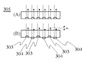
また、カンチレバーセンサーは、図5に示すように参照用および検出用カンチレバーを配置してもよい。図5において、検出用カンチレバー503と参照用カンチレバー504は向きが反対で、かつ、交互に配置されている。図5においては、カンチレバー支持部502が、参照用カンチレバーと検出用カンチレバーで共通となっているが、参照用カンチレバー支持部と、検出用カンチレバー支持部とに分かれていてもよい。
Further, the cantilever sensor may include a reference and detection cantilever as shown in FIG. In FIG. 5, the detection cantilevers 503 and the reference cantilevers 504 are opposite in direction and are alternately arranged. In FIG. 5, the
また、センサーの形状はカンチレバーに限定されるものではなく、特定の分子の吸着や、温度などの環境の変化等によって形状が変化するものであればよい。 Further, the shape of the sensor is not limited to the cantilever, and any shape may be used as long as the shape changes due to adsorption of specific molecules, changes in environment such as temperature, and the like.
次に、本発明に関わるメカニカルセンサーの検出原理に関して詳細に説明する。図6(A)は検出用カンチレバーからの反射光と参照用カンチレバーからの反射光がなす干渉パターンである。干渉パターンは、明線601と暗線602からなり、検出用カンチレバーのたわみと参照用カンチレバーのたわみとの差Dhの変化にともなって明線601の位置や間隔が変化する。従ってCCDやCMOSセンサーなどのイメージセンサーで干渉パターン603を撮影し、明線601の位置やピッチを測定することで検出用カンチレバーのたわみと参照用カンチレバーのたわみの差Dhを測定することが可能となる。
また、干渉パターン603内の任意の箇所にフォトダイオードなど受光素子を配置すると、その出力は図6(B)に示すようになる。図6(B)において、横軸は、検出用カンチレバーのたわみと参照用カンチレバーのたわみの差Dh、縦軸は、受光素子の出力の大きさIである。Dhに対するIの変化は、検出に用いる光の波長の1/4毎に周期的に変化する。従って、受光素子の出力を測定することで、その変化から、Dhを求めることが可能となる。
Next, the detection principle of the mechanical sensor according to the present invention will be described in detail. FIG. 6A shows an interference pattern formed by the reflected light from the detection cantilever and the reflected light from the reference cantilever. The interference pattern includes a
When a light receiving element such as a photodiode is arranged at an arbitrary position in the
以上、述べたように本発明の実施の形態によれば、照射光源の数が少なくてすみ、照射光の位置あわせが容易に行え、また、カンチレバーのピッチが光源の位置あわせ精度に影響されることなく自由に設定可能になり、検出用カンチレバーと参照用カンチレバーを近接させることが可能となる。さらに、参照用カンチレバーのたわみと検出用カンチレバーのたわみの差を直接測定できるため、キャリブレーションすることなく定量的測定を行えるようになる。 As described above, according to the embodiment of the present invention, the number of irradiation light sources can be reduced, the alignment of irradiation light can be easily performed, and the pitch of the cantilever is influenced by the alignment accuracy of the light source. The detection cantilever and the reference cantilever can be brought close to each other. Furthermore, since the difference between the deflection of the reference cantilever and the deflection of the detection cantilever can be directly measured, quantitative measurement can be performed without calibration.
次に、本発明に関わるメカニカルセンサーを用いた分析システムに関して説明する。図7は、分析システムの中核をなす分析プレートの概略図である。分析プレート701には、反応部702が形成されている。反応部702は、交互に配置された検出用カンチレバー704と参照用カンチレバー705と、液溜部706を有す。液溜部706を測定対象となる液体で満たし、先に述べた方法で、検出用カンチレバーのたわみと、参照用カンチレバーのたわみとの差Dhを測定することで、検出対象となる物質が存在するか検査することができる。
ここで、Dhを測定するための光源と受光器は、少なくとも一組で各反応部をスキャンしてもよいし、反応部702毎に配置してもよい。また、本説明においては一組の検出用カンチレバー704と参照用カンチレバー705毎に液溜部が配置されている構造を示したが、各反応部702の液溜部が結合した構造としてもよい。
Next, an analysis system using a mechanical sensor according to the present invention will be described. FIG. 7 is a schematic view of an analysis plate forming the core of the analysis system. A
Here, the light source and the light receiver for measuring Dh may scan at least one set of each reaction unit, or may be arranged for each
101、501 ビームスポット
102、502 カンチレバー支持部
103、403、503、703 参照用カンチレバー
104、404、504、704 検出用カンチレバー
105 カンチレバーセンサー
109 カンチレバー基材
110 反射膜および抗体固定膜
111 抗体
205、405 光源
206 反射鏡
207、407 受光器
208 ビームスプリッタ
701 分析プレート
702 反応部
706 液溜部
1001 XYZトランスレータ
1002 試料ステージ
1003 試料
1004 カンチレバー
1005 カンチレバーのたわみ検出器
1006 コントローラ
1007 コンピュータ
101, 501
Claims (3)
前記測定手段は、
前記複数の検出手段及び前記複数の参照手段の全てを含むビームスポット(101、501)で光を照射する光照射手段と、
前記検出手段で反射した反射光と前記参照手段で反射した反射光との干渉光を受光する受光手段と、
前記干渉光に対応する干渉光データを用いて前記固体の形状変化を測定する形状変化測定部とを備え、
前記受光手段は、イメージセンサーから構成されており、
前記干渉光データは、前記干渉光の強度データである明線データと前記明線データよりも弱い強度データである暗線データとを備え、
前記形状変化測定部は、前記イメージセンサーにおける前記明線データ及び前記暗線データのいずれか一方のピッチの変化を用いることを特徴とするメカニカルセンサー。 A plurality of cantilever-like detection means, a plurality of cantilever-like reference means, and a measurement means for measuring a change in shape between the detection means and the reference means. by measuring the shape change of the solid caused by the temperature and changes in the environment, in the mechanical sensor for detecting the change in molecular and environment, and the detection means and said reference means are arranged alternately with each other,
The measuring means includes
A light irradiation means for irradiating light with a beam spot (101, 501) including all of the plurality of detection means and the plurality of reference means;
A light receiving means for receiving interference light between the reflected light reflected by the detecting means and the reflected light reflected by the reference means;
A shape change measuring unit that measures the shape change of the solid using interference light data corresponding to the interference light,
The light receiving means is composed of an image sensor,
The interference light data includes bright line data that is intensity data of the interference light and dark line data that is intensity data weaker than the bright line data.
The shape change measuring unit uses a change in pitch of one of the bright line data and the dark line data in the image sensor.
Priority Applications (1)
| Application Number | Priority Date | Filing Date | Title |
|---|---|---|---|
| JP2004097821A JP4898097B2 (en) | 2003-10-31 | 2004-03-30 | Mechanical sensor and analysis system using the same |
Applications Claiming Priority (3)
| Application Number | Priority Date | Filing Date | Title |
|---|---|---|---|
| JP2003372866 | 2003-10-31 | ||
| JP2003372866 | 2003-10-31 | ||
| JP2004097821A JP4898097B2 (en) | 2003-10-31 | 2004-03-30 | Mechanical sensor and analysis system using the same |
Publications (2)
| Publication Number | Publication Date |
|---|---|
| JP2005156525A JP2005156525A (en) | 2005-06-16 |
| JP4898097B2 true JP4898097B2 (en) | 2012-03-14 |
Family
ID=34741293
Family Applications (1)
| Application Number | Title | Priority Date | Filing Date |
|---|---|---|---|
| JP2004097821A Expired - Fee Related JP4898097B2 (en) | 2003-10-31 | 2004-03-30 | Mechanical sensor and analysis system using the same |
Country Status (1)
| Country | Link |
|---|---|
| JP (1) | JP4898097B2 (en) |
Families Citing this family (1)
| Publication number | Priority date | Publication date | Assignee | Title |
|---|---|---|---|---|
| KR101338032B1 (en) * | 2007-05-04 | 2013-12-09 | 엘지전자 주식회사 | Nano data storage system based on scanning probe microscope |
Family Cites Families (7)
| Publication number | Priority date | Publication date | Assignee | Title |
|---|---|---|---|---|
| JPH03123805A (en) * | 1989-10-09 | 1991-05-27 | Olympus Optical Co Ltd | Interatomic force microscope |
| JPH04179042A (en) * | 1990-11-13 | 1992-06-25 | Olympus Optical Co Ltd | Cantilever for scanning probe microscope |
| JPH04188022A (en) * | 1990-11-22 | 1992-07-06 | Olympus Optical Co Ltd | Displacement detecting apparatus |
| US5280341A (en) * | 1992-02-27 | 1994-01-18 | International Business Machines Corporation | Feedback controlled differential fiber interferometer |
| JP3761906B2 (en) * | 1992-11-06 | 2006-03-29 | 日立建機株式会社 | Scanning probe microscope and its control error correction method |
| WO1995002180A1 (en) * | 1993-07-06 | 1995-01-19 | International Business Machines Corporation | Calorimetric sensor |
| US6096559A (en) * | 1998-03-16 | 2000-08-01 | Lockheed Martin Energy Research Corporation | Micromechanical calorimetric sensor |
-
2004
- 2004-03-30 JP JP2004097821A patent/JP4898097B2/en not_active Expired - Fee Related
Also Published As
| Publication number | Publication date |
|---|---|
| JP2005156525A (en) | 2005-06-16 |
Similar Documents
| Publication | Publication Date | Title |
|---|---|---|
| EP1892727B1 (en) | Shape measuring apparatus using an interferometric displacement gauge | |
| KR101161881B1 (en) | Inspection apparatus for detecting defects in transparent substrates | |
| JP5112650B2 (en) | Method and system for determining drift of the position of a light beam relative to a chuck | |
| JP3709431B2 (en) | High-speed measuring device for angle-dependent diffraction effects on microstructured surfaces | |
| JPH05256641A (en) | Cantilever displacement detector | |
| KR20090113895A (en) | Apparatus for Measuring Defects in a Glass Sheet | |
| US8345260B2 (en) | Method of detecting a movement of a measuring probe and measuring instrument | |
| US6884981B2 (en) | Diffractive optical position detector | |
| Schulz et al. | Scanning deflectometric form measurement avoiding path-dependent angle measurement errors | |
| JP2022070996A (en) | Apparatus and method for scanning probe microscope | |
| US20120212748A1 (en) | Optical reader systems and methods for microplate position detection | |
| JP5548848B2 (en) | Inspection apparatus, inspection method, and semiconductor device manufacturing method | |
| JP4898097B2 (en) | Mechanical sensor and analysis system using the same | |
| KR102646539B1 (en) | scanning probe microscope | |
| NL2022264A (en) | Apparatus and methods for determining the position of a target structure on a substrate | |
| CN111398295B (en) | Defect detection device and method thereof | |
| KR101173607B1 (en) | Bio sensor apparatus having real-time ditection about physical change of bio matter and method of sensing | |
| KR101881752B1 (en) | defect sensing module based on line-beam and defect sensing device using its arrays for detection of the defects on surface | |
| JP6185701B2 (en) | Shape measuring device | |
| JPH0921629A (en) | Apparatus for evaluating foreign article | |
| JP4143722B2 (en) | Sensitivity calibration method for atomic force / horizontal force microscope | |
| JP5777068B2 (en) | Mask evaluation device | |
| JP2005147745A (en) | Apparatus for measuring near-field scattered light | |
| JP2021015027A (en) | Inspection device and inspection method | |
| JPH10213587A (en) | Scanning type probe microscope |
Legal Events
| Date | Code | Title | Description |
|---|---|---|---|
| A621 | Written request for application examination |
Free format text: JAPANESE INTERMEDIATE CODE: A621 Effective date: 20070328 |
|
| A131 | Notification of reasons for refusal |
Free format text: JAPANESE INTERMEDIATE CODE: A131 Effective date: 20091006 |
|
| A521 | Written amendment |
Free format text: JAPANESE INTERMEDIATE CODE: A523 Effective date: 20091110 |
|
| RD01 | Notification of change of attorney |
Free format text: JAPANESE INTERMEDIATE CODE: A7421 Effective date: 20091113 |
|
| A02 | Decision of refusal |
Free format text: JAPANESE INTERMEDIATE CODE: A02 Effective date: 20100223 |
|
| A521 | Written amendment |
Free format text: JAPANESE INTERMEDIATE CODE: A523 Effective date: 20100514 |
|
| A911 | Transfer of reconsideration by examiner before appeal (zenchi) |
Free format text: JAPANESE INTERMEDIATE CODE: A911 Effective date: 20100528 |
|
| A912 | Removal of reconsideration by examiner before appeal (zenchi) |
Free format text: JAPANESE INTERMEDIATE CODE: A912 Effective date: 20100702 |
|
| A521 | Written amendment |
Free format text: JAPANESE INTERMEDIATE CODE: A523 Effective date: 20111115 |
|
| A521 | Written amendment |
Free format text: JAPANESE INTERMEDIATE CODE: A523 Effective date: 20111124 |
|
| A01 | Written decision to grant a patent or to grant a registration (utility model) |
Free format text: JAPANESE INTERMEDIATE CODE: A01 |
|
| A61 | First payment of annual fees (during grant procedure) |
Free format text: JAPANESE INTERMEDIATE CODE: A61 Effective date: 20111226 |
|
| R150 | Certificate of patent or registration of utility model |
Ref document number: 4898097 Country of ref document: JP Free format text: JAPANESE INTERMEDIATE CODE: R150 Free format text: JAPANESE INTERMEDIATE CODE: R150 |
|
| FPAY | Renewal fee payment (event date is renewal date of database) |
Free format text: PAYMENT UNTIL: 20150106 Year of fee payment: 3 |
|
| S111 | Request for change of ownership or part of ownership |
Free format text: JAPANESE INTERMEDIATE CODE: R313113 |
|
| R350 | Written notification of registration of transfer |
Free format text: JAPANESE INTERMEDIATE CODE: R350 |
|
| R250 | Receipt of annual fees |
Free format text: JAPANESE INTERMEDIATE CODE: R250 |
|
| R250 | Receipt of annual fees |
Free format text: JAPANESE INTERMEDIATE CODE: R250 |
|
| R250 | Receipt of annual fees |
Free format text: JAPANESE INTERMEDIATE CODE: R250 |
|
| R250 | Receipt of annual fees |
Free format text: JAPANESE INTERMEDIATE CODE: R250 |
|
| R250 | Receipt of annual fees |
Free format text: JAPANESE INTERMEDIATE CODE: R250 |
|
| LAPS | Cancellation because of no payment of annual fees |