JP4893334B2 - Image tracking device and imaging device - Google Patents
Image tracking device and imaging device Download PDFInfo
- Publication number
- JP4893334B2 JP4893334B2 JP2007016437A JP2007016437A JP4893334B2 JP 4893334 B2 JP4893334 B2 JP 4893334B2 JP 2007016437 A JP2007016437 A JP 2007016437A JP 2007016437 A JP2007016437 A JP 2007016437A JP 4893334 B2 JP4893334 B2 JP 4893334B2
- Authority
- JP
- Japan
- Prior art keywords
- image
- focus adjustment
- focus
- tracking
- focus detection
- Prior art date
- Legal status (The legal status is an assumption and is not a legal conclusion. Google has not performed a legal analysis and makes no representation as to the accuracy of the status listed.)
- Active
Links
- 238000003384 imaging method Methods 0.000 title claims description 12
- 238000001514 detection method Methods 0.000 claims description 94
- 230000003287 optical effect Effects 0.000 claims description 23
- 230000008859 change Effects 0.000 claims description 4
- 238000000034 method Methods 0.000 description 29
- 230000008569 process Effects 0.000 description 26
- 230000006870 function Effects 0.000 description 6
- 230000011514 reflex Effects 0.000 description 6
- 238000006243 chemical reaction Methods 0.000 description 2
- 238000010586 diagram Methods 0.000 description 2
- 239000004973 liquid crystal related substance Substances 0.000 description 2
- 230000002093 peripheral effect Effects 0.000 description 2
- 125000002066 L-histidyl group Chemical group [H]N1C([H])=NC(C([H])([H])[C@](C(=O)[*])([H])N([H])[H])=C1[H] 0.000 description 1
- 238000009825 accumulation Methods 0.000 description 1
- 230000004907 flux Effects 0.000 description 1
- 239000011159 matrix material Substances 0.000 description 1
- 238000005375 photometry Methods 0.000 description 1
- 238000007781 pre-processing Methods 0.000 description 1
- 238000003825 pressing Methods 0.000 description 1
- 210000001747 pupil Anatomy 0.000 description 1
- 230000004044 response Effects 0.000 description 1
Images


Landscapes
- Studio Devices (AREA)
- Focusing (AREA)
- Automatic Focus Adjustment (AREA)
Description
本発明は画像追尾装置および撮像装置に関する。 The present invention relates to an image tracking device and an imaging device.
撮影画面内に設定された複数の焦点検出エリアにおいて撮影レンズのデフォーカス量を検出し、いずれかのエリアのデフォーカス量に基づいて撮影レンズを合焦駆動する自動焦点調節(AF)機能と、撮影画像の中の追尾対象の被写体の画像をテンプレート画像(基準画像)として記憶し、繰り返し撮像される画像の中でテンプレート画像と同一または類似した画像の位置を検索しながら追尾対象の被写体を追尾する画像追尾機能とを備え、画像追尾結果の画面内位置の焦点検出エリアを選択してその焦点検出エリアのデフォーカス量により撮影レンズを合焦駆動するオートフォーカスシステムが知られている(例えば、特許文献1参照)。
この装置では、画像追尾結果の画面内位置の画像によりテンプレート画像を更新している。
An automatic focus adjustment (AF) function for detecting the defocus amount of the photographing lens in a plurality of focus detection areas set in the photographing screen and driving the photographing lens based on the defocus amount of any area; The image of the subject to be tracked in the photographed image is stored as a template image (reference image), and the subject to be tracked is tracked while searching for the position of the same or similar image as the template image in the repeatedly captured image. There is known an autofocus system that includes an image tracking function for selecting a focus detection area at an in-screen position of an image tracking result and driving the photographing lens in focus by a defocus amount of the focus detection area (for example, Patent Document 1).
In this apparatus, the template image is updated with the image at the position in the screen as the image tracking result.
この出願の発明に関連する先行技術文献としては次のものがある。
ところで、画像追尾機能により被写体を追尾しているときに、追尾対象の被写体の手前を別の被写体が横切ったり、また追尾対象の被写体が撮影画面から外れてしまったり、あるいは撮影者が意図的に構図を変更することがあり、そのような場合には追尾対象を見失ってしまい画像追尾ができなくなる。
そこで、画像追尾により対象被写体を見失ってからふたたび捕捉するまでAFにおけるレンズ駆動を一時中止し(ロックオン)、再捕捉できないまま所定時間が経過した場合、または再捕捉できた場合にロックオンを解除してAFを再開させることが考えられる。しかしながら、このような場合には追尾対象の状態が変わっているため、適切な画像追尾ができなくなるという問題がある。
By the way, when tracking a subject with the image tracking function, another subject crosses in front of the subject to be tracked, the subject to be tracked is off the shooting screen, or the photographer intentionally The composition may be changed. In such a case, the tracking target is lost and image tracking cannot be performed.
Therefore, the lens drive in AF is temporarily stopped (locked on) until it is captured again after losing the target subject by image tracking, and the lock-on is released when a predetermined time has passed without being recaptured or when it can be recaptured. Then, it is conceivable to resume AF. However, in such a case, since the state of the tracking target has changed, there is a problem that appropriate image tracking cannot be performed.
(1)請求項1の画像追尾装置は、光学系による画面内の画像情報を取得する撮像素子と、前記画像情報の内の対象の位置の画像情報を基準情報として記憶する記憶手段と、前記撮像素子により繰り返し取得される前記画像情報と前記基準情報とに基づいて、前記画面内における前記対象の位置を繰り返し認識する認識手段と、前記画面内に設定される焦点検出位置についての前記光学系の焦点調節状態を検出する焦点検出手段と、前記認識手段により認識した前記対象の位置に対応する前記焦点検出位置の前記焦点調節状態にしたがって焦点調節制御を行う焦点調節制御手段と、前記対象の位置に対応する前記焦点検出位置の前記焦点調節状態の変化量が所定値を超えた場合に前記焦点調節を一時的に中止させる制御手段と、前記制御手段により前記焦点調節が中止されてから再開された場合に、前記基準情報を変更する変更手段と、を備えることを特徴とする。
(2)請求項2の画像追尾装置は、請求項1に記載の画像追尾装置において、前記制御手段は、前記焦点検出手段の検出結果が、前記焦点調節の中止前の前記対象の位置に対応する前記焦点検出位置の前記焦点調節状態と同等であることを示す場合に、前記焦点調節を再開させることを特徴とする。
(3)請求項3の画像追尾装置は、請求項2に記載の画像追尾装置において、前記変更手段は、前記焦点調節の再開後に得られる前記画像情報の内の、前記同等の検出結果が得られる領域の画像情報に基づいて前記基準情報を変更することを特徴とする。
(4)請求項4の画像追尾装置は、光学系による画面内の画像情報を取得する撮像素子と、前記画像情報の内の対象の位置の画像情報を基準情報として記憶する記憶手段と、前記撮像素子により繰り返し取得される前記画像情報と前記基準情報とに基づいて、前記画面内における前記対象の位置を繰り返し認識する認識手段と、前記画面内に設定される焦点検出位置についての前記光学系の焦点調節状態を検出する焦点検出手段と、前記認識手段により認識した前記対象の位置に対応する前記焦点検出位置の前記焦点調節状態にしたがって焦点調節制御を行う焦点調節制御手段と、前記焦点検出手段の検出結果に基づいて前記焦点調節を一時的に中止させる制御手段と、前記制御手段により前記焦点調節が中止されてから再開された場合に、前記基準情報を変更する変更手段と、を備え、前記制御手段は、前記焦点検出手段の検出結果が、前記焦点調節の中止前の前記対象の位置に対応する前記焦点検出位置の前記焦点調節状態と同等であることを示す場合に、前記焦点調節を再開させることを特徴とする。
(5)請求項5の画像追尾装置は、請求項4に記載の画像追尾装置において、前記変更手段は、前記焦点調節の再開後に得られる前記画像情報の内の、前記同等の検出結果が得られる領域の画像情報に基づいて前記基準情報を変更することを特徴とする。
(6)請求項6の画像追尾装置は、請求項1〜5のいずれか一項に記載の画像追尾装置において、前記画像情報は、色に関する情報と輝度に関する情報の内の少なくとも一つであることを特徴とする。
(7)請求項7の撮像装置は、請求項1〜6のいずれか一項に記載の画像追尾装置を備えることを特徴とする。
(1) The image tracking device according to
(2) The image tracking device according to
(3) The image tracking device according to claim 3 is the image tracking device according to
(4) An image tracking device according to a fourth aspect of the present invention is an image pickup device for acquiring image information within a screen by an optical system , storage means for storing image information of a target position in the image information as reference information, Recognizing means that repeatedly recognizes the position of the target in the screen based on the image information and the reference information repeatedly acquired by the image sensor, and the optical system for the focus detection position set in the screen A focus detection unit that detects a focus adjustment state of the target, a focus adjustment control unit that performs focus adjustment control according to the focus adjustment state of the focus detection position corresponding to the position of the object recognized by the recognition unit, and the focus detection Control means for temporarily stopping the focus adjustment based on the detection result of the means, and when the focus adjustment is stopped by the control means and then restarted, Change means for changing the reference information, and the control means has the focus adjustment state of the focus detection position corresponding to the target position before the focus adjustment is stopped, as a result of detection by the focus detection means. The focus adjustment is resumed when it is shown that it is equivalent to.
(5) The image tracking device according to claim 5 is the image tracking device according to
(6) The image tracking device according to claim 6 is the image tracking device according to any one of
(7) An image pickup apparatus according to a seventh aspect includes the image tracking apparatus according to any one of the first to sixth aspects .
本発明によれば、焦点調節の再開後に基準画像を適切に更新することができ、撮影者の意図する被写体を追尾することができる。 According to the present invention, the reference image can be appropriately updated after the focus adjustment is resumed, and the subject intended by the photographer can be tracked.
撮影画面内に設定された複数の焦点検出エリアにおいて撮影レンズのデフォーカス量を検出し、いずれかのエリアのデフォーカス量に基づいて撮影レンズを合焦駆動する自動焦点調節(AF)機能と、撮影画像の中の追尾対象の被写体の画像をテンプレート画像(基準画像)として記憶し、繰り返し撮像される画像の中でテンプレート画像と同一または類似した画像の位置を検索しながら(テンプレートマッチング)追尾対象の被写体を追尾する画像追尾機能とを備え、画像追尾結果の画面内位置の焦点検出エリアを選択してその焦点検出エリアのデフォーカス量により撮影レンズを合焦駆動する画像追尾装置を備えた撮像装置(一眼レフデジタルスチルカメラ)の一実施の形態を説明する。 An automatic focus adjustment (AF) function for detecting the defocus amount of the photographing lens in a plurality of focus detection areas set in the photographing screen and driving the photographing lens based on the defocus amount of any area; The image of the subject to be tracked in the captured image is stored as a template image (reference image), and the tracking target is searched while searching for the position of the same or similar image as the template image in the repeatedly captured image (template matching) An image tracking function for tracking a subject, and an image tracking device that selects a focus detection area at an in-screen position of the image tracking result and drives the photographing lens in focus by the defocus amount of the focus detection area An embodiment of an apparatus (single-lens reflex digital still camera) will be described.
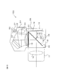
図1は、一実施の形態の被写体追尾装置を備えた撮像装置(一眼レフデジタルスチルカメラ)100の構成を示す。カメラ本体10には交換レンズ11が交換可能に装着されている。カメラ本体10には、被写体像を撮像して画像を記録するための第1撮像素子12が設けられている。この第1撮像素子12はCCDやCMOSなどにより構成することができる。撮影時にはクイックリターンミラー13が実線で示す撮影光路外の位置に退避してシャッター14が開放され、撮影レンズ15により第1撮像素子12の受光面に被写体像が結像される。
FIG. 1 shows a configuration of an imaging apparatus (single-lens reflex digital still camera) 100 including an object tracking device according to an embodiment. An
カメラ本体10の底部には、撮影レンズ15の焦点調節状態を検出するための焦点検出光学系16と測距素子17が設けられている。この一実施の形態では、瞳分割位相差検出方式による焦点検出方法を採用した例を示す。焦点検出光学系16は、撮影レンズ15を通過した対の焦点検出用光束を測距素子17の受光面へ導き、対の光像を結像させる。測距素子17は例えば一対のCCDラインセンサーを備え、対の光像に応じた焦点検出信号を出力する。撮影前にはクイックリターンミラー13が破線で示すような撮影光路内の位置に設定されており、撮影レンズ15からの対の焦点検出用光束はクイックリターンミラー13のハーフミラー部を透過し、サブミラー18により反射されて焦点検出光学系16および測距素子17へ導かれる。
At the bottom of the camera body 10, a focus detection
カメラ本体10の上部にはファインダー光学系が設けられている。撮影前にはクイックリターンミラー13が破線で示す位置にあり、撮影レンズ15からの被写体光は焦点板20へ導かれ、焦点板20上に被写体像が結像する。液晶表示素子21は、焦点板20上に結像された被写体像に焦点検出エリアマークなどの情報を重畳表示するとともに、被写体像外の位置に露出値などの種々の撮影情報を表示する。焦点板20上の被写体像はペンタダハプリズム22および接眼レンズ23を介して接眼窓24へ導かれ、撮影者が被写体像を視認することができる。
A finder optical system is provided on the upper part of the camera body 10. Prior to shooting, the
また、カメラ本体10上部のファインダー光学系には、被写体追尾や測光のために被写体像を撮像する第2撮像素子25が設けられている。この第2撮像素子25については詳細を後述する。焦点板20に結像した被写体像は、ペンタダハプリズム22、プリズム26および結像レンズ27を介して第2撮像素子25の受光面に再結像される。第2撮像素子25は被写体像に応じた画像信号を出力する。
The finder optical system at the top of the camera body 10 is provided with a
カメラ本体10にはまた、操作部材28、制御装置29、レンズ駆動装置30が設けられる。操作部材28には、シャッターボタンや焦点検出エリア選択スイッチなどのカメラ100を操作するためのスイッチやセレクターが含まれる。制御装置29はCPUとその周辺部品から構成され、カメラ100の各種制御と演算などを行う。また、レンズ駆動装置30はモーターと駆動回路から構成され、撮影レンズ15の焦点調節を行う。
The camera body 10 is also provided with an
図2は制御装置29の詳細な構成を示す。なお、本願発明と直接関係のない制御機能については図示と説明を省略する。制御装置29はマイクロコンピューターのソフトウエア形態により構成される各種制御部を備えている。CCD制御部31は第2撮像素子25の電荷の蓄積と読み出しを制御する。A/D変換部32は、第2撮像素子25から出力されるアナログ画像信号を画像情報としてのデジタル画像信号に変換する。露出演算部33は、第2撮像素子25により撮像した画像信号に基づいて露出値を演算する。
FIG. 2 shows a detailed configuration of the
焦点検出演算部34は、測距素子17から出力される対の光像に応じた焦点検出信号に基づいて撮影レンズ15の焦点調節状態、ここではデフォーカス量を検出する。なお、詳細を後述するが、撮影レンズ15の撮影画面内には複数の位置に焦点検出位置としての焦点検出エリアが設定されており、測距素子17は焦点検出エリアごとに対の光像に応じた焦点検出信号を出力し、焦点検出演算部34は焦点検出エリアごとに対の光像に応じた焦点検出信号に基づいてデフォーカス量を検出する。レンズ駆動量演算部35は検出されたデフォーカス量をレンズ駆動量に変換する。レンズ駆動装置30は、レンズ駆動量にしたがって撮影レンズ15のフォーカシングレンズ(不図示)を駆動し、焦点調節を行う。
The focus
追尾制御部36は、第2撮像素子25により撮像した被写体像の内、撮影者が手動で指定した追尾対象位置、あるいはカメラ100が自動で設定した追尾対象位置に対応する画像をテンプレート画像として後述の記憶部37に記憶させるとともに、その追尾対象位置の撮影レンズ15のデフォーカス量を焦点検出演算部34に検出させる。そして、その後に繰り返し撮像される画像の中からテンプレート画像と一致または類似する画像領域を検索することにより対象の位置を認識するとともに、テンプレート画像と一致または類似する画像領域に対応した焦点検出位置における撮影レンズ15のデフォーカス量を検出し、その検出結果を前回の追尾対象領域において検出されたデフォーカス量と比較して大きな変化がなければ、検索された画像領域に対応する焦点検出位置で合焦制御を行う。このような手順を繰り返し、特定の被写体を追尾する。記憶部37は、追尾制御部36による追尾動作中のテンプレート画像やデフォーカス量などの情報、あるいは撮影レンズ15の焦点距離、開放F値、絞り値、像ズレ量/デフォーカス量の変換係数などのレンズ情報を記憶する。
The
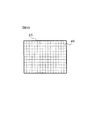
図3は第2撮像素子25の詳細な構成を示す正面図である。第2撮像素子25は、マトリクス状に配列された複数の画素(光電変換素子)40(ここでは横16個×縦12個=192個)を備えている。各画素40は図4に示すように3個の部分40a、40b、40cに分割され、これらの部分40a、40b、40cにはそれぞれ赤R、緑G、青Bの原色フィルターが設けられている。これにより、各画素40ごとに被写体像のRGB信号を出力することができる。
FIG. 3 is a front view showing a detailed configuration of the
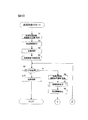
次に、一実施の形態の被写体追尾動作を説明する。図5は一実施の形態の被写体追尾方法を説明するための図、図6〜図9は一実施の形態の被写体追尾処理を示すフローチャートである。制御装置29は、第2撮像素子25により撮像した被写体像の内、撮影者が手動で追尾対象位置を指定するか、あるいはカメラ100が自動で追尾対象位置を設定した後、操作部材28のシャッターボタンを半押しすると被写体追尾処理を開始する。
Next, a subject tracking operation according to an embodiment will be described. FIG. 5 is a diagram for explaining a subject tracking method according to an embodiment, and FIGS. 6 to 9 are flowcharts illustrating subject tracking processing according to the embodiment. The
なお、シャッターボタンを全押しして撮影を行うとき以外は、クイックリターンミラー13は図1に破線で示す撮影光路内に設定されており、撮影レンズ15から入射した被写体光は焦点板20上に結像される。そして、焦点板20上の被写体像はペンタダハプリズム22、プリズム26および結像レンズ27を介して第2撮像素子25へ導かれ、第2撮像素子25から被写体像が繰り返し出力される。
The
撮影レンズ15の撮影画面には複数の位置に焦点検出エリアが設定されており、液晶表示素子21により焦点板20上の被写体像にエリアマークを重畳し、各焦点検出エリアの位置を表示する。この一実施の形態では、図5に示すように、撮影画面内の11カ所に焦点検出エリア45a〜45kが設定された例を示す。また、操作部材28の焦点検出エリア選択スイッチにより任意のエリアを選択すると、そのエリアのマークが点灯表示される。
Focus detection areas are set at a plurality of positions on the photographing screen of the photographing
例えば、被写体像に対応する焦点検出エリア45fを操作部材28の焦点検出エリア選択スイッチにより選択すると、焦点検出エリア45fのマークが点灯(ここでは黒色表示)され、この状態で操作部材28のシャッターボタンを半押しすることによって、追尾対称の被写体を指定することができる。また、この半押し操作に応じて制御装置29は被写体追尾処理を開始する。
For example, when the
図6のステップ1において、第2撮像素子25により追尾初期画像(被写体追尾処理を開始して最初に取得する画像)を取得するとともに、測距素子17により選択焦点検出エリア(ここでは、45f)に対応する対の光像を取得する。続くステップ2では、測距素子17により取得した焦点検出エリア45fに対応する対の光像に基づいて焦点検出エリア45fのデフォーカス量(撮影レンズ15の焦点調節状態)を検出する。ステップ3で、選択された焦点検出エリア45fに対して検出されたデフォーカス量をレンズ駆動量に変換し、レンズ駆動装置30により撮影レンズ15を駆動して焦点調節を行う。
In
ステップ4において、図8に示す追尾制御の初期処理を実行する。図8のステップ101において、追尾初期画像の中の焦点検出エリア45fの位置に対応する位置の画像を被写体色情報として記憶する。ステップ102では、図5(a)に示すように、追尾初期画像の中の焦点検出エリア45fの位置周辺部において被写体色情報と同様な色情報を示す同色情報領域を検出し、続くステップ103で同色情報領域を初期の追尾被写体領域47とする。ステップ104において、追尾初期画像の中の追尾被写体領域47の画像を次回の追尾処理に用いるテンプレート画像48(図5(b)参照)として記憶部37に記憶し、ステップ105で追尾被写体領域47を中心に前後左右に所定画素(ここでは2画素とする)ずつ拡大した領域を探索領域49に設定する。その後、図6のステップ5へリターンする。
In
なお、この一実施の形態では被写体色情報に基づいて追尾被写体領域47を決定する例を示すが、輝度情報に基づいて追尾被写体領域47を決定してもよく、処理の簡素化を図るために一律4×4画素の領域サイズとしたり、撮影レンズ15の焦点距離情報に応じて領域サイズを決定してもよい。
In this embodiment, the tracking
追尾制御の初期処理を終了したら図6のステップ5へ進み、操作部材28のシャッターボタンが全押しされたか否か、つまりシャッターレリーズ操作が行われたか否かを確認する。シャッターレリーズ操作が行われた場合はステップ9へ進み、ミラー13をアップしてシャッター14を開放し、第1撮像素子12により撮像を行う。一方、シャッターレリーズ操作が行われていない場合はステップ6へ進み、第2撮像素子25から次の画像情報を取得するとともに、測距素子17により各焦点検出エリア45a〜45kごとに焦点検出用の対の光像を取得する。
When the initial processing of the tracking control is completed, the process proceeds to step 5 in FIG. 6 to check whether or not the shutter button of the
ステップ7において、図9に示す追尾演算処理を行う。図9のステップ201において、追尾次画像の中の探索領域49からテンプレート画像48と同じサイズの領域を順次切り出し、切り出した画像とテンプレート画像48の対応する画素ごとに画像情報の差分を算出し、全画素に対する差分の総和を求める。ここで、例えば各画素の色相B/G、R/Gの差分を画像情報の差分とする場合には、第2撮像素子25から出力される生の画像信号を用いて演算することができるため、生の画像信号に対するホワイトバランスやフィルター処理などの前処理を必要とせず、追尾処理の簡素化を図ることができる。なお、色相差に代えて画素ごとの色の差を演算するようにしてもよい。輝度情報に基づいて追尾被写体領域47を決定する場合は、画素ごとの輝度差を演算してもよい。
In step 7, the tracking calculation process shown in FIG. 9 is performed. In step 201 in FIG. 9, an area having the same size as the
探索領域49から切り出したすべての画像に対してテンプレート画像48との差分の総和演算が終了したら、演算結果の中で差分の総和値が最も小さい切り出し画像を選び、その切り出し画像の領域を新しい追尾被写体領域47に決定することにより対象の位置を認識する。ステップ203で、新しい追尾被写体領域47を中心に前後左右に所定画素(ここでは2画素とする)ずつ拡大した領域を新しい探索領域49に設定する。その後、図6のステップ8へリターンする。
When the summation of differences from the
リターン後の図6のステップ8において、測距素子17により取得した各焦点検出エリア45a〜45kに対応する対の光像に基づいて各焦点検出エリアのデフォーカス量(撮影レンズ15の焦点調節状態)を検出する。続く図7のステップ11ではAFにおけるレンズ駆動の一時中止(この明細書では、ロックオンという)を示すロックオンF(フラグ)がセット(ロックオンF=1)されているか否か、すなわちロックオンの実行中か否かを確認する。ロックオンフラグがリセット(ロックオンF=0)されてロックオンが実行されていないときはステップ12へ進み、AFによるロックオン条件が成立するか否かを判定する。
In
ここで、一実施の形態のAFロックオン条件について説明する。今回の画像追尾において新しい追尾被写体領域47の位置に対応する焦点検出エリア(45a〜45kのいずれか)で検出されたデフォーカス量をDnとし、前回の画像追尾において追尾被写体領域47の位置に対応する焦点検出エリア(45a〜45kのいずれか)で検出されたデフォーカス量をDn-1としたとき、前回と今回の画像追尾位置でのデフォーカス量の差(Dn−Dn-1)が、予め設定した同一被写体と見なせる判定基準値を超える場合には、AFロックオン条件が成立するとし、追尾被写体が入れ替わったと判断してロックオンを開始する。
Here, an AF lock-on condition according to an embodiment will be described. In the current image tracking, the defocus amount detected in the focus detection area (any one of 45a to 45k) corresponding to the position of the new
なお、前回の画像追尾において追尾被写体領域47の位置に対応する焦点検出エリアで検出されたデフォーカス量Dn-1は、今回の画像追尾においてデフォーカス量の差(Dn−Dn-1)が判定基準値を超える前の、つまり“被写体はずし”が発生する前の、さらに換言すればロックオン開始直前の、追尾対象の被写体を正しく捕捉しているときのデフォーカス量であり、後述するAFロックオン解除判定に用いるためにデフォーカス量Dn-0として制御装置29の記憶部37に記憶しておく。
The defocus amount Dn-1 detected in the focus detection area corresponding to the position of the tracking
AFロックオン条件が成立する場合はステップ15へ進み、成立しない場合はステップ13へ進む。AFロックオン条件が成立しない場合は、ステップ13で画像追尾によるロックオン条件が成立するか否かを判定する。
If the AF lock-on condition is satisfied, the process proceeds to step 15, and if not, the process proceeds to step 13. If the AF lock-on condition is not satisfied, it is determined in
ここで、一実施の形態の画像追尾ロックオン条件について説明する。画像追尾において、ステップ6で得た追尾次画像の中の探索領域49からテンプレート画像48と同じサイズの領域を順次切り出し、切り出した画像とテンプレート画像48の対応する画素ごとの画像情報の差分の総和値、この一実施の形態では画素ごとの色相B/G、R/Gの差分の総和値を算出する。そして、切り出した画像の中で総和値が最も小さい切り出し画像の領域を新しい追尾被写体領域47に決定するが、この最少の総和値が予め設定した同一被写体と見なせる判定基準値を超える場合には、画像追尾ロックオン条件が成立するとし、追尾対象の被写体を見失ったと判断してロックオンを開始する。
Here, the image tracking lock-on condition according to the embodiment will be described. In image tracking, an area having the same size as the
AFロックオン条件と画像追尾ロックオン条件の内の少なくとも一方が成立する場合はステップ15へ進み、撮影レンズ15の合焦制御を行わず、ロックオンフラグをセット(1)するとともに、制御装置29の内蔵タイマー(不図示)によりロックオンを開始してからの経過時間の計時を開始する。その後、図6のステップ5へ戻って上述した処理を繰り返す。一方、AFロックオン条件と画像追尾ロックオン条件のどちらも成立しない場合はステップ14へ進み、ロックオンを開始せずに、今回の画像追尾における新しい追尾被写体領域47の位置に対応する焦点検出エリア(45a〜45kのいずれか)で検出されたデフォーカス量Dnに基づき、撮影レンズ15の合焦制御を行う。
If at least one of the AF lock-on condition and the image tracking lock-on condition is satisfied, the process proceeds to step 15, the focus control of the taking
ステップ11でロックオンフラグがセット(ロックオンF=1)されてロックオンがすでに実行されているときはステップ16へ進み、ロックオンを開始してから予め設定した所定のロックオン時間が経過したか否かを確認し、予め設定したロックオン時間が経過していないときはステップ17へ進む。ここで、ロックオン時間の設定値には、これ以上待っても後述するロックオン解除条件が成立してロックオン開始前の追尾対象の被写体を再捕捉できる確率は極めて低いと判断できる適当な時間またはカメラのカスタムセッティングにてユーザーが自分の好みなどに応じた時間を設定する。ステップ17ではAFロックオン解除条件が成立しているか否かを判別する。
When the lock-on flag is set (lock-on F = 1) in
ここで、AFロックオン解除条件について説明する。上述したように、今回の画像追尾において新しい追尾被写体領域47の位置に対応する焦点検出エリアで検出されたデフォーカス量Dnと、前回の画像追尾において追尾被写体領域47の位置に対応する焦点検出エリアで検出されたデフォーカス量Dn-1との差(Dn−Dn-1)が、予め設定した同一被写体と見なせる判定基準値を超える場合にはAFロックオン条件が成立し、ロックオンを開始した。
Here, the AF lock-on release condition will be described. As described above, the defocus amount Dn detected in the focus detection area corresponding to the position of the new
この一実施の形態では、ステップ8において焦点検出エリア(45a〜45kのいずれか)で検出されたデフォーカス量の中から、制御装置29の記憶部37に記憶されているデフォーカス量Dn-0、つまりAFロックオン開始直前の追尾対象の被写体を正しく捕捉しているときのデフォーカス量Dn-0との差が、上述した予め設定した同一被写体と見なせる判定基準値以下になるものがある場合には、AFロックオンの解除条件が成立するとし、最もDn-0との差が小さくなるデフォーカス量が検出された焦点検出エリア(45a〜45kのいずれか)を新追尾被写体領域47とし、追尾対象の被写体をふたたび捕捉したと判断してロックオンを解除する。
In this embodiment, the defocus amount Dn-0 stored in the
AFロックオン解除条件が成立した場合はステップ19へ進み、成立していない場合はステップ18へ進む。AFロックオン解除条件が成立していない場合は、ステップ18で画像追尾のロックオン解除条件が成立しているか否かを判定する。
If the AF lock-on release condition is satisfied, the process proceeds to step 19, and if not, the process proceeds to step 18. If the AF lock-on release condition is not satisfied, it is determined in
ここで、画像追尾ロックオン解除条件について説明する。上述したように、画像追尾において追尾次画像の中の探索領域49からテンプレート画像48と同じサイズの領域を順次切り出し、切り出した画像とテンプレート画像48の対応する画素ごとの画像情報の差分の総和値を算出し、切り出した画像の総和値の中で最も小さい総和値が予め設定した同一被写体と見なせる判定基準値を超える場合には画像追尾ロックオン条件が成立し、ロックオンを開始した。
Here, the image tracking lock-on release condition will be described. As described above, in the image tracking, an area having the same size as the
この一実施の形態では、ステップ6で得られる追尾次画像の中の探索領域49からテンプレート画像48と同じサイズの領域を順次切り出し、切り出した画像とテンプレート画像48の対応する画素ごとの画像情報の差分、この一実施の形態では画素ごとの色相B/G、R/Gの差分の総和値を算出する。そして、切り出した画像の総和値の中で最も小さい総和値が予め設定した同一被写体と見なせる判定基準値以下になった場合には、画像追尾のロックオン解除条件が成立するとし、追尾対象の被写体をふたたび捕捉したと判断してロックオンを解除する。
In this embodiment, an area of the same size as the
なお、テンプレート画像48はいったんロックオンが開始されるとロックオンが解除されるまで更新されないため、ロックオン解除を判定する時点におけるテンプレート画像48はロックオン開始直前のテンプレート画像のままである。
Since the
AFロックオン解除条件が成立する場合は、ロックオン開始前に追尾していた対象被写体をふたたび捕捉したと判断してステップ19へ進む。ステップ19ではロックオンフラグをリセット(ロックオンF=0)し、続くステップ20において、ステップ17にて最もDn-0との差が小さくなるデフォーカス量が検出された焦点検出エリア(45a〜45kのいずれか)で、検出されたデフォーカス量Dnに基づいて撮影レンズ15の合焦制御を行う。次に、ステップ21において、新追尾被写体領域47(ステップ17)の画像を新しいテンプレート画像48として制御装置29の記憶部37に記憶し、テンプレート画像の更新を行う。
このようにAFロックオン解除条件が成立する場合とは、ロックオン開始前と比較してデフォーカス量の差が判定基準値より小さく、追尾対象とカメラ100との距離の変化量が小さい場合である。このような結果が得られる状況の一例として、追尾対象とカメラ100との間を別の被写体が横切って、カメラ100が該被写体を認識することによりAFロックオン条件がいったん成立してしまう場合が考えられる。この際、別の被写体が横切っている間に追尾対象が向きを変えてしまうと、ロックオン開始前のテンプレート画像では認識できないが、この一実施の形態によればデフォーカス量に基づいてロックオン開始後も追尾対象を認識し、かつテンプレート画像を変更するので、ロックオン解除後も追尾することが可能である。
画像追尾ロックオン解除条件が成立する場合は、ロックオン開始前に追尾していた対象被写体を再捕捉したと判断してステップ25へ進む。ステップ25ではロックオンフラグをリセット(ロックオンF=0)し、続くステップ26で、今回の画像追尾において検出された新追尾被写体領域47の位置に対応する焦点検出エリアで検出されたデフォーカス量に基づいて撮影レンズ15の合焦制御を行う。
If the AF lock-on release condition is satisfied, it is determined that the target subject that has been tracked before the lock-on start is captured again, and the process proceeds to step 19. In
In this way, the AF lock-on release condition is satisfied when the defocus amount difference is smaller than the determination reference value and the change amount of the distance between the tracking target and the
If the image tracking lock-on release condition is satisfied, it is determined that the target subject that has been tracked before the start of lock-on is recaptured, and the process proceeds to step 25. In
一方、AFロックオン解除条件と画像追尾ロックオン解除条件のどちらも成立しない場合は、ロックオン開始前に追尾していた対象被写体を捕捉できなかった判断し、ロックオンを継続してステップ5へ戻り、上述した処理を繰り返す。 On the other hand, if neither the AF lock-on release condition nor the image tracking lock-on release condition is satisfied, it is determined that the target subject that was being tracked before the start of lock-on could not be captured, and lock-on is continued and step 5 is continued. Return and repeat the process described above.
ステップ16でロックオンを開始してから予め設定したロックオン時間が経過したと判断された場合はステップ22へ進み、これ以上待っても後述するロックオン解除条件が成立して当初の追尾対象の被写体を再捕捉できる確率は極めて低いため、ロックオンを解除する処理を行う。まず、ステップ22でロックオンフラグをリセット(ロックオンF=0)する。次に、ステップ23において、ステップ8で再び検出した焦点検出エリア45a〜45kの最新のデフォーカス量の中で最至近を示すデフォーカス量を選択し、最至近のデフォーカス量に基づいて撮影レンズ15の合焦制御を行う。そして、ステップ24で今回合焦制御を行った焦点検出エリアに対応する領域を追尾対象領域47として、その領域の画像を新しいテンプレート画像48として制御部28の記憶部37に記憶し、テンプレート画像48の変更を行う。
If it is determined in
なお、予め設定したロックオン時間の経過によりロックオンを解除した後、画面内の複数の焦点検出エリアで検出された複数のデフォーカス量の中から最至近を示すデフォーカス量を選択して焦点調節を行う例を示したが、ロックオン時間経過後のAFはこの一実施の形態に限定されない。 After releasing the lock-on after a preset lock-on time has passed, the focus is selected by selecting the closest defocus amount from a plurality of defocus amounts detected in a plurality of focus detection areas in the screen. Although an example in which adjustment is performed is shown, AF after the lock-on time has elapsed is not limited to this embodiment.
このように、一実施の形態によれば、ロックオン解除後に基準画像を適切に変更することができ、撮影者の意図する被写体を追尾し続けることができる。 Thus, according to the embodiment, the reference image can be appropriately changed after the lock-on is released, and the subject intended by the photographer can be continuously tracked.
なお、上述した一実施の形態では、本発明を一眼レフデジタルスチルカメラに適用した実施例を説明したが、本発明は時系列的に画像を取得可能な撮像装置であればどのような装置でも実現可能であり、一眼レフデジタルスチルカメラ以外の、例えばコンシューマデジタルカメラや動画像を取得する撮像装置としてのビデオカメラなどにも本発明を適用することができる。 In the above-described embodiment, the embodiment in which the present invention is applied to a single-lens reflex digital still camera has been described. However, the present invention is not limited to any imaging device that can acquire images in time series. The present invention can be applied to, for example, a consumer digital camera or a video camera as an imaging device that acquires a moving image other than a single-lens reflex digital still camera.
10 カメラ本体
11 交換レンズ
17 測距素子
25 第2撮像素子
29 制御装置
30 レンズ駆動装置
34 焦点検出演算部
35 レンズ駆動量演算部
36 追尾制御部
37 記憶部
100 一眼レフデジタルカメラ
DESCRIPTION OF SYMBOLS 10 Camera
Claims (7)
前記画像情報の内の対象の位置の画像情報を基準情報として記憶する記憶手段と、
前記撮像素子により繰り返し取得される前記画像情報と前記基準情報とに基づいて、前記画面内における前記対象の位置を繰り返し認識する認識手段と、
前記画面内に設定される焦点検出位置についての前記光学系の焦点調節状態を検出する焦点検出手段と、
前記認識手段により認識した前記対象の位置に対応する前記焦点検出位置の前記焦点調節状態にしたがって焦点調節制御を行う焦点調節制御手段と、
前記対象の位置に対応する前記焦点検出位置の前記焦点調節状態の変化量が所定値を超えた場合に前記焦点調節を一時的に中止させる制御手段と、
前記制御手段により前記焦点調節が中止されてから再開された場合に、前記基準情報を変更する変更手段と、を備えることを特徴とする画像追尾装置。 An image sensor for acquiring image information in the screen by an optical system;
Storage means for storing image information at a target position in the image information as reference information;
Recognition means for repeatedly recognizing the position of the target in the screen based on the image information and the reference information repeatedly acquired by the imaging device;
Focus detection means for detecting a focus adjustment state of the optical system for a focus detection position set in the screen;
Focus adjustment control means for performing focus adjustment control according to the focus adjustment state of the focus detection position corresponding to the position of the object recognized by the recognition means;
Control means for temporarily stopping the focus adjustment when an amount of change in the focus adjustment state of the focus detection position corresponding to the target position exceeds a predetermined value ;
An image tracking apparatus comprising: a changing unit that changes the reference information when the focus adjustment is resumed after being stopped by the control unit.
前記制御手段は、前記焦点検出手段の検出結果が、前記焦点調節の中止前の前記対象の位置に対応する前記焦点検出位置の前記焦点調節状態と同等であることを示す場合に、前記焦点調節を再開させることを特徴とする画像追尾装置。 The image tracking device according to claim 1,
The control means, when the detection result of the focus detection means indicates that the focus adjustment state of the focus detection position corresponding to the position of the object before the focus adjustment is stopped is equivalent to the focus adjustment state. The image tracking device is characterized by resuming .
前記変更手段は、前記焦点調節の再開後に得られる前記画像情報の内の、前記同等の検出結果が得られる領域の画像情報に基づいて前記基準情報を変更することを特徴とする画像追尾装置。 The image tracking device according to claim 2,
The image tracking apparatus according to claim 1, wherein the changing unit changes the reference information based on image information of an area where the equivalent detection result can be obtained in the image information obtained after the focus adjustment is resumed .
前記画像情報の内の対象の位置の画像情報を基準情報として記憶する記憶手段と、
前記撮像素子により繰り返し取得される前記画像情報と前記基準情報とに基づいて、前記画面内における前記対象の位置を繰り返し認識する認識手段と、
前記画面内に設定される焦点検出位置についての前記光学系の焦点調節状態を検出する焦点検出手段と、
前記認識手段により認識した前記対象の位置に対応する前記焦点検出位置の前記焦点調節状態にしたがって焦点調節制御を行う焦点調節制御手段と、
前記焦点検出手段の検出結果に基づいて前記焦点調節を一時的に中止させる制御手段と、
前記制御手段により前記焦点調節が中止されてから再開された場合に、前記基準情報を変更する変更手段と、を備え、
前記制御手段は、前記焦点検出手段の検出結果が、前記焦点調節の中止前の前記対象の位置に対応する前記焦点検出位置の前記焦点調節状態と同等であることを示す場合に、前記焦点調節を再開させることを特徴とする画像追尾装置。 An image sensor for acquiring image information in the screen by an optical system;
Storage means for storing image information at a target position in the image information as reference information;
Recognition means for repeatedly recognizing the position of the target in the screen based on the image information and the reference information repeatedly acquired by the imaging device;
Focus detection means for detecting a focus adjustment state of the optical system for a focus detection position set in the screen;
Focus adjustment control means for performing focus adjustment control according to the focus adjustment state of the focus detection position corresponding to the position of the object recognized by the recognition means;
Control means for temporarily stopping the focus adjustment based on a detection result of the focus detection means;
Changing means for changing the reference information when the focus adjustment is resumed after being stopped by the control means,
The control means, when the detection result of the focus detection means indicates that the focus adjustment state of the focus detection position corresponding to the position of the object before the focus adjustment is stopped is equivalent to the focus adjustment state. The image tracking device is characterized by resuming .
前記変更手段は、前記焦点調節の再開後に得られる前記画像情報の内の、前記同等の検出結果が得られる領域の画像情報に基づいて前記基準情報を変更することを特徴とする画像追尾装置。 The image tracking device according to claim 4 ,
The image tracking apparatus according to claim 1, wherein the changing unit changes the reference information based on image information of an area where the equivalent detection result can be obtained in the image information obtained after the focus adjustment is resumed .
前記画像情報は、色に関する情報と輝度に関する情報の内の少なくとも一つであることを特徴とする画像追尾装置。 In the image tracking device according to any one of claims 1 to 5 ,
The image tracking apparatus , wherein the image information is at least one of information on color and information on luminance .
Priority Applications (1)
| Application Number | Priority Date | Filing Date | Title |
|---|---|---|---|
| JP2007016437A JP4893334B2 (en) | 2007-01-26 | 2007-01-26 | Image tracking device and imaging device |
Applications Claiming Priority (1)
| Application Number | Priority Date | Filing Date | Title |
|---|---|---|---|
| JP2007016437A JP4893334B2 (en) | 2007-01-26 | 2007-01-26 | Image tracking device and imaging device |
Publications (3)
| Publication Number | Publication Date |
|---|---|
| JP2008187231A JP2008187231A (en) | 2008-08-14 |
| JP2008187231A5 JP2008187231A5 (en) | 2011-03-10 |
| JP4893334B2 true JP4893334B2 (en) | 2012-03-07 |
Family
ID=39730008
Family Applications (1)
| Application Number | Title | Priority Date | Filing Date |
|---|---|---|---|
| JP2007016437A Active JP4893334B2 (en) | 2007-01-26 | 2007-01-26 | Image tracking device and imaging device |
Country Status (1)
| Country | Link |
|---|---|
| JP (1) | JP4893334B2 (en) |
Families Citing this family (9)
| Publication number | Priority date | Publication date | Assignee | Title |
|---|---|---|---|---|
| JP2010054586A (en) * | 2008-08-26 | 2010-03-11 | Nikon Corp | Focusing device and imaging apparatus |
| JP5409483B2 (en) * | 2010-03-30 | 2014-02-05 | 富士フイルム株式会社 | Imaging device |
| JP5604160B2 (en) * | 2010-04-09 | 2014-10-08 | パナソニック株式会社 | Imaging device |
| JP5888069B2 (en) * | 2012-03-30 | 2016-03-16 | 株式会社ニコン | Area determination apparatus, imaging apparatus, and area determination program |
| JP6145822B2 (en) * | 2012-10-12 | 2017-06-14 | パナソニックIpマネジメント株式会社 | Imaging device |
| JP5789725B2 (en) * | 2012-11-22 | 2015-10-07 | 富士フイルム株式会社 | Imaging apparatus, focusing method thereof and focusing control program |
| JP2014095915A (en) * | 2014-01-06 | 2014-05-22 | Nikon Corp | Focus adjustment device and imaging device |
| JP2016028298A (en) * | 2015-10-07 | 2016-02-25 | 株式会社ニコン | Focus adjustment device and imaging device |
| JP2018063439A (en) * | 2017-12-05 | 2018-04-19 | 株式会社ニコン | Focus adjustment device and imaging device |
Family Cites Families (4)
| Publication number | Priority date | Publication date | Assignee | Title |
|---|---|---|---|---|
| JPS6134516A (en) * | 1984-07-26 | 1986-02-18 | Canon Inc | Camera |
| JP2743931B2 (en) * | 1988-05-13 | 1998-04-28 | 株式会社ニコン | Automatic focusing device |
| JP4092636B2 (en) * | 2002-11-01 | 2008-05-28 | フジノン株式会社 | Auto focus system |
| JP2004251930A (en) * | 2003-02-17 | 2004-09-09 | Nikon Corp | Autofocus camera |
-
2007
- 2007-01-26 JP JP2007016437A patent/JP4893334B2/en active Active
Also Published As
| Publication number | Publication date |
|---|---|
| JP2008187231A (en) | 2008-08-14 |
Similar Documents
| Publication | Publication Date | Title |
|---|---|---|
| JP5157256B2 (en) | Image tracking device and imaging device | |
| JP5082631B2 (en) | Imaging device | |
| JP5167750B2 (en) | TRACKING DEVICE, IMAGING DEVICE, AND TRACKING METHOD | |
| JP5176483B2 (en) | Image recognition device, image tracking device, and imaging device | |
| JP4893334B2 (en) | Image tracking device and imaging device | |
| JP5247076B2 (en) | Image tracking device, focus adjustment device, and imaging device | |
| JP4872834B2 (en) | Image recognition device, focus adjustment device, and imaging device | |
| JP2009109839A (en) | Image tracking device and imaging device | |
| JP5056136B2 (en) | Image tracking device | |
| JP5403111B2 (en) | Image tracking device | |
| JP2007133301A (en) | Autofocus camera | |
| JP4888249B2 (en) | Focus detection apparatus and imaging apparatus | |
| JP4985155B2 (en) | Focus adjustment device and imaging device | |
| JP2014197141A (en) | Imaging apparatus | |
| JP2003084192A (en) | Camera | |
| JP5447579B2 (en) | Tracking device, focus adjustment device, and photographing device | |
| JP2010054586A (en) | Focusing device and imaging apparatus | |
| JP6699679B2 (en) | Imaging device | |
| JP5233646B2 (en) | Image tracking device, imaging device, and image tracking method | |
| JP5772933B2 (en) | Imaging device | |
| JP2012093775A (en) | Focus detector and imaging apparatus | |
| JP2015187662A (en) | Focus adjustment device and imaging apparatus | |
| JP4973369B2 (en) | Image processing apparatus and imaging apparatus | |
| JP2009303113A (en) | Electronic camera | |
| JP2018063439A (en) | Focus adjustment device and imaging device |
Legal Events
| Date | Code | Title | Description |
|---|---|---|---|
| A621 | Written request for application examination |
Free format text: JAPANESE INTERMEDIATE CODE: A621 Effective date: 20100119 |
|
| A521 | Request for written amendment filed |
Free format text: JAPANESE INTERMEDIATE CODE: A523 Effective date: 20100128 |
|
| RD02 | Notification of acceptance of power of attorney |
Free format text: JAPANESE INTERMEDIATE CODE: A7422 Effective date: 20100128 |
|
| A521 | Request for written amendment filed |
Free format text: JAPANESE INTERMEDIATE CODE: A523 Effective date: 20110119 |
|
| A977 | Report on retrieval |
Free format text: JAPANESE INTERMEDIATE CODE: A971007 Effective date: 20110601 |
|
| A131 | Notification of reasons for refusal |
Free format text: JAPANESE INTERMEDIATE CODE: A131 Effective date: 20110607 |
|
| A521 | Request for written amendment filed |
Free format text: JAPANESE INTERMEDIATE CODE: A523 Effective date: 20110808 |
|
| A131 | Notification of reasons for refusal |
Free format text: JAPANESE INTERMEDIATE CODE: A131 Effective date: 20110830 |
|
| A521 | Request for written amendment filed |
Free format text: JAPANESE INTERMEDIATE CODE: A523 Effective date: 20111031 |
|
| TRDD | Decision of grant or rejection written | ||
| A01 | Written decision to grant a patent or to grant a registration (utility model) |
Free format text: JAPANESE INTERMEDIATE CODE: A01 Effective date: 20111122 |
|
| A01 | Written decision to grant a patent or to grant a registration (utility model) |
Free format text: JAPANESE INTERMEDIATE CODE: A01 |
|
| A61 | First payment of annual fees (during grant procedure) |
Free format text: JAPANESE INTERMEDIATE CODE: A61 Effective date: 20111205 |
|
| R150 | Certificate of patent or registration of utility model |
Ref document number: 4893334 Country of ref document: JP Free format text: JAPANESE INTERMEDIATE CODE: R150 Free format text: JAPANESE INTERMEDIATE CODE: R150 |
|
| FPAY | Renewal fee payment (event date is renewal date of database) |
Free format text: PAYMENT UNTIL: 20150106 Year of fee payment: 3 |
|
| FPAY | Renewal fee payment (event date is renewal date of database) |
Free format text: PAYMENT UNTIL: 20150106 Year of fee payment: 3 |
|
| R250 | Receipt of annual fees |
Free format text: JAPANESE INTERMEDIATE CODE: R250 |
|
| R250 | Receipt of annual fees |
Free format text: JAPANESE INTERMEDIATE CODE: R250 |
|
| R250 | Receipt of annual fees |
Free format text: JAPANESE INTERMEDIATE CODE: R250 |
|
| R250 | Receipt of annual fees |
Free format text: JAPANESE INTERMEDIATE CODE: R250 |
|
| R250 | Receipt of annual fees |
Free format text: JAPANESE INTERMEDIATE CODE: R250 |
|
| R250 | Receipt of annual fees |
Free format text: JAPANESE INTERMEDIATE CODE: R250 |
|
| R250 | Receipt of annual fees |
Free format text: JAPANESE INTERMEDIATE CODE: R250 |
|
| R250 | Receipt of annual fees |
Free format text: JAPANESE INTERMEDIATE CODE: R250 |
|
| R250 | Receipt of annual fees |
Free format text: JAPANESE INTERMEDIATE CODE: R250 |
|
| R250 | Receipt of annual fees |
Free format text: JAPANESE INTERMEDIATE CODE: R250 |