JP4890179B2 - Plasma MIG welding method - Google Patents
Plasma MIG welding method Download PDFInfo
- Publication number
- JP4890179B2 JP4890179B2 JP2006262094A JP2006262094A JP4890179B2 JP 4890179 B2 JP4890179 B2 JP 4890179B2 JP 2006262094 A JP2006262094 A JP 2006262094A JP 2006262094 A JP2006262094 A JP 2006262094A JP 4890179 B2 JP4890179 B2 JP 4890179B2
- Authority
- JP
- Japan
- Prior art keywords
- plasma
- arc
- mig
- welding
- current
- Prior art date
- Legal status (The legal status is an assumption and is not a legal conclusion. Google has not performed a legal analysis and makes no representation as to the accuracy of the status listed.)
- Active
Links
Images

Description
本発明は、ビード形状を調整することができるプラズマミグ溶接方法に関するものである。 The present invention relates to a plasma MIG welding method capable of adjusting a bead shape.
非消耗のプラズマ電極と母材との間にプラズマアークを発生させると共に、プラズマ電極を中空形状としその中空内を通って絶縁された消耗電極(溶接ワイヤ)を送給し、この消耗電極と母材との間にミグアークを発生させて溶接するプラズマミグ溶接方法が従来から使用されている。このプラズマミグ溶接方法では、プラズマアーク中を溶接ワイヤが送給されてプラズマアーク中にミグアークが発生する。したがって、溶接ワイヤはプラズマアーク及びミグアークの両方から加熱されて溶融し溶滴移行する。このために、ミグアークが適正なアーク長を維持して安定状態になるには、両アークからの加熱による溶融速度と溶接ワイヤの送給速度とがバランスする必要がある。このバランスを取るために、プラズマ電流、ミグアーク電流、ミグアーク電圧、送給速度等を安定する範囲に組み合わせて設定する必要がある。上記のプラズマ電極には、水冷銅電極、タングスレン電極等が使用される。プラズマミグ溶接方法では、同時に2つのアークを発生させながら溶接を行うので、高効率な溶接を行うことができる。 A plasma arc is generated between the non-consumable plasma electrode and the base material, the plasma electrode is hollow, and an insulated consumable electrode (welding wire) is fed through the hollow. 2. Description of the Related Art Conventionally, a plasma MIG welding method in which a MIG arc is generated and welded to a material has been used. In this plasma MIG welding method, a welding wire is fed through a plasma arc, and a MIG arc is generated in the plasma arc. Therefore, the welding wire is heated from both the plasma arc and the MIG arc, melts, and moves into droplets. For this reason, in order for the MIG arc to maintain a proper arc length and to be in a stable state, it is necessary to balance the melting rate by heating from both arcs and the welding wire feed rate. In order to achieve this balance, it is necessary to set the plasma current, the MIG arc current, the MIG arc voltage, the feeding speed, etc. in combination within a stable range. A water-cooled copper electrode, a tungsten electrode, or the like is used as the plasma electrode. In the plasma MIG welding method, welding is performed while simultaneously generating two arcs, so that highly efficient welding can be performed.
上述したプラズマミグ溶接方法において、溶接品質を向上させることを目的として、プラズマアーク中の溶接ワイヤの位置又は角度を変化させることによって、ビード形状(余盛り高さ、ビード幅、溶け込み深さ等)を制御することができる(例えば、特許文献1、2参照)。
In the plasma MIG welding method described above, the bead shape (recess height, bead width, penetration depth, etc.) is changed by changing the position or angle of the welding wire in the plasma arc for the purpose of improving the welding quality. It can be controlled (see, for example,
上述したように、高品質な溶接を行うためには、ワークの要求品質に応じて所望のビード形状を形成する必要がある。所望のビード形状とは、余盛り高さ、ビード幅、溶け込み深さ等が所望値であることである。ワークの要求品質によって適正なビード形状が異なるので、ビード形状が適正になるように溶接条件を調整する必要がある。 As described above, in order to perform high-quality welding, it is necessary to form a desired bead shape according to the required quality of the workpiece. The desired bead shape means that the extra height, bead width, penetration depth, and the like are desired values. Since the appropriate bead shape varies depending on the required quality of the workpiece, it is necessary to adjust the welding conditions so that the bead shape is appropriate.
上述した従来技術のプラズマミグ溶接方法において、ビード形状を所望形状に調整するためには、プラズマ電流、ミグアーク電流、ミグアーク電圧のうち少なくとも一つ以上を調整する必要がある。しかし、これらの設定値を変化させると、プラズマアーク及び/又はミグアークによる溶接ワイヤへの加熱状態が大きく変化することになり、ミグアークはアーク長が変化して安定性が悪くなることが多い。すなわち、ミグアークの安定性はプラズマ電流値、ミグアーク電流値、ミグアーク電圧値、溶接ワイヤの送給速度等が適正な組み合わせ範囲にあるときに確保される。ビード形状を調整するためにこれらの設定値を変化させると、適正な組み合わせ範囲外になり、アーク安定性が悪くなる。したがって、上記の設定値は、ミグアークの安定性を確保できる範囲においてビード形状が所望形状になるように調整する必要がある。このために、溶接条件の設定が難しくなる上に、ビード形状をあまり変化させることができなかった。 In the above-described conventional plasma MIG welding method, in order to adjust the bead shape to a desired shape, it is necessary to adjust at least one of plasma current, MIG arc current, and MIG arc voltage. However, when these set values are changed, the heating state of the welding wire by the plasma arc and / or the MIG arc changes greatly, and the MIG arc often changes in arc length and becomes unstable. That is, the stability of the MIG arc is ensured when the plasma current value, the MIG arc current value, the MIG arc voltage value, the feeding speed of the welding wire, etc. are in an appropriate combination range. If these set values are changed in order to adjust the bead shape, it is outside the proper combination range, and the arc stability is deteriorated. Therefore, it is necessary to adjust the set value so that the bead shape becomes a desired shape within a range in which the stability of the MIG arc can be secured. For this reason, setting of welding conditions becomes difficult and the bead shape cannot be changed so much.
また、上述したように、プラズマアーク中における溶接ワイヤの位置又は角度を調整することで、ビード形状を変化させることができる。しかし、この方法は、溶接ワイヤを可動させる機構を必要とするために溶接トーチの大型化を招き、ワークとの干渉が生じやすくなり適用範囲が限定されていた。 Further, as described above, the bead shape can be changed by adjusting the position or angle of the welding wire in the plasma arc. However, this method requires a mechanism for moving the welding wire, leading to an increase in the size of the welding torch, which tends to cause interference with the workpiece, and has a limited application range.
そこで、本発明では、ミグアークを安定に維持したままで溶接トーチを大型化することもなくビード形状を所望形状に容易に調整することができるプラズマミグ溶接方法を提供する。 Therefore, the present invention provides a plasma MIG welding method capable of easily adjusting the bead shape to a desired shape without increasing the size of the welding torch while maintaining the MIG arc stably.
上述した課題を解決するために、第1の発明は、非消耗のプラズマ電極と母材との間にプラズマアークを発生させると共に、前記プラズマ電極を中空形状としその中空内を通って絶縁された消耗電極を送給し、前記消耗電極と母材との間にミグアークを発生させて溶接するプラズマミグ溶接方法において、
前記プラズマアークに通電するプラズマ電流を予め定めた周波数でパルス状に変化させ、前記プラズマ電流の平均値を略一定値に維持したままで、継手部のギャップが第1の値であるときの前記周波数を前記ギャップが前記第1の値よりも大きな値の第2の値であるときの前記周波数よりも高く設定する、
ことを特徴とするプラズマミグ溶接方法である。
In order to solve the above-described problems, the first invention generates a plasma arc between a non-consumable plasma electrode and a base material, and the plasma electrode is formed in a hollow shape and insulated through the hollow. In the plasma MIG welding method of feeding a consumable electrode and generating a MIG arc between the consumable electrode and the base material and welding,
The plasma current to be supplied to the plasma arc is changed in a pulse shape at a predetermined frequency, and the average value of the plasma current is maintained at a substantially constant value, and the gap of the joint portion is the first value. Setting a frequency higher than the frequency when the gap is a second value greater than the first value;
This is a plasma MIG welding method.
上記第1の発明によれば、プラズマ電流をパルス状とし平均値を略一定値に維持した上でその周波数を変化させることによって、ミグアークを安定に維持したままでビード形状を所望形状に調整することができる。プラズマ電流の周波数を変化させるだけなので、溶接トーチは通常のままであり、溶接条件の設定も容易である。 According to the first aspect of the invention, the bead shape is adjusted to a desired shape while the MIG arc is stably maintained by changing the frequency while maintaining the average value at a substantially constant value with the plasma current being pulsed. be able to. Since only the frequency of the plasma current is changed, the welding torch remains normal and the welding conditions can be easily set.
さらに、上記第1の発明によれば、ギャップのある継手に対するプラズマミグ溶接において、ギャップの大きさに応じてプラズマ電流の周波数を適正値に変化させることによって、適正なビード形状を得ることができる。
Furthermore, according to the first invention, in plasma MIG welding for a joint having a gap, an appropriate bead shape can be obtained by changing the frequency of the plasma current to an appropriate value in accordance with the size of the gap.
以下、図面を参照して本発明の実施の形態について説明する。 Embodiments of the present invention will be described below with reference to the drawings.
[実施の形態1]
図1は、本発明の実施の形態1に係るプラズマミグ溶接装置の構成図である。以下、同図を参照して説明する。
[Embodiment 1]
FIG. 1 is a configuration diagram of a plasma MIG welding apparatus according to
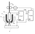
プラズマ電極1bはプラズマノズル4に囲まれており、プラズマノズル4内をアルゴンガス等のプラズマガスが高速に流れ、母材2との間にプラズマアーク3bが発生する。プラズマノズル4はさらにシールドノズル5に囲まれており、アルゴンガス等のシールドガスが流れる。プラズマアーク3b中をプラズマ溶接電源PSPから供給されたプラズマ電流Iwbが通電する。プラズマ電極1bには、水冷銅電極、タングステン電極等が使用され、内部が中空構造になっている。同図では、プラズマアーク3bは電極プラス極性で発生している。プラズマアーク3bが電極マイナス極性でも良い。
The
ミグ溶接電源PSMは、送給モータMの回転を制御する送給制御信号Fcを出力すると共に、ミグアーク電流Iwa及びミグアーク電圧Vwaを出力する。溶接ワイヤ1aは、送給モータMに結合された送給ロール6によって送給される。溶接ワイヤ1aは、上記のプラズマ電極1bの中空内を絶縁されて送給されて、母材2との間にミグアーク3aが発生する。このミグアーク3aはプラズマアーク3bに内包されて発生する。したがって、溶接ワイヤ1aはプラズマアーク3b及びミグアーク3aから加熱されて溶滴移行する。ミグアーク3aは電極プラス極性で発生している。溶接ワイヤ1aの送給速度がFw[m/分]となる。
The MIG welding power source PSM outputs a feed control signal Fc for controlling the rotation of the feed motor M, and also outputs a MIG arc current Iwa and a MIG arc voltage Vwa. The welding wire 1a is fed by a
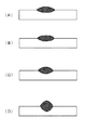
上記のプラズマ電流Iwbとして、図2に示すように、パルス状の電流を通電する。予め定めたピーク期間Tp中は予め定めたピーク電流Ipを通電し、予め定めたベース期間Tb中は予め定めたベース電流Ibを通電し、これらの通電を1周期1/fとして繰り返し行う。プラズマ電流Iwbの平均値をIavとすると、この平均値Iavを所定値に維持したままでパルス波形の周波数f[Hz]を変化させる。ここでf=0も含むので、そのときは値がIavの直流電流となる。Tp/(Tp+Tb)で示すデューティは、0.5に限らず任意の値に設定する。一般的に、アークからの入熱はアークを通電する電流の平均値に略比例する。したがって、プラズマ電流Iwbの平均値Iavが一定であれば、溶接ワイヤへの加熱も略一定となる。このために、ミグアークが安定した状態にあつときに、平均値Iavを一定に維持したままでプラズマ電流Iwbの周波数fを変化させても安定状態には影響を与えない。プラズマ電流Iwbの周波数fが変化すると、プラズマアークの硬直性(集中性)が変化する。この結果、溶融池へのアーク圧力の分布が変化するために、ビード形状が変化する。
As the plasma current Iwb, a pulsed current is applied as shown in FIG. A predetermined peak current Ip is applied during a predetermined peak period Tp, a predetermined base current Ib is applied during a predetermined base period Tb, and these energizations are repeated as 1
図3は、プラズマ電流の周波数fを変化させたときのビード形状の変化を示すビード断面図である。同図は、溶接ワイヤにAl−Mg合金ワイヤ(A5356、1.2mm径)を使用し、母材に板厚6mmのAl−Mg合金板(A5052)を使用した場合である。また、同図は、プラズマ電流Iwbの平均値Iav=150A、溶接ワイヤの送給速度Fw=10m/分、ミグアーク電流Iwa=100A、ミグアーク電圧Vwa=19V、溶接速度50cm/分で溶接したときのビード形状である。プラズマ電流Iwbの波形パラメータを、Ip=200A、Ib=100A、Tp=Tbとした場合である。同図(A)は周波数f=0Hz(直流)のときであり、同図(B)は周波数f=5Hzのときであり、同図(C)は周波数f=50Hzのときであり、同図(D)は周波数f=500Hzのときである。 FIG. 3 is a bead cross-sectional view showing changes in the bead shape when the frequency f of the plasma current is changed. This figure shows a case where an Al—Mg alloy wire (A5356, 1.2 mm diameter) is used as the welding wire and an Al—Mg alloy plate (A5052) having a plate thickness of 6 mm is used as the base material. The figure shows the case where welding is performed at an average value of plasma current Iwb Iav = 150 A, welding wire feed speed Fw = 10 m / min, MIG arc current Iwa = 100 A, MIG arc voltage Vwa = 19 V, and welding speed 50 cm / min. The bead shape. This is a case where the waveform parameters of the plasma current Iwb are Ip = 200A, Ib = 100A, and Tp = Tb. FIG. 4A shows the frequency f = 0 Hz (DC), FIG. 4B shows the frequency f = 5 Hz, and FIG. 4C shows the frequency f = 50 Hz. (D) is when the frequency f = 500 Hz.
同図(A)〜(D)では、プラズマ電流Iwb及びミグアーク電流Iwaの平均値が変化していないので、母材への入熱は略一定になり溶け込み断面積は略一定のままである。他方、余盛り高さ、ビード幅及び溶け込み深さは周波数fに応じて大きく変化する。すなわち、周波数fが低周波のときはプラズマアークの硬直性が弱くなり、アークの広がりによって溶け込みが浅くビード幅の広いビード形状になる。周波数fが高周波のときはプラズマークの硬直性が強くなり、アークは集中してアーク力も増加するために、溶け込みが深くビード幅が狭く余盛りの高いビード形状になる。 In FIGS. 4A to 4D, since the average values of the plasma current Iwb and the MIG arc current Iwa are not changed, the heat input to the base material becomes substantially constant and the penetration cross-sectional area remains substantially constant. On the other hand, the surplus height, the bead width, and the penetration depth vary greatly according to the frequency f. That is, when the frequency f is low, the rigidity of the plasma arc is weakened, and the arc spreads to form a bead shape with a shallow penetration and a wide bead width. When the frequency f is high, the rigidity of the plasmak becomes strong, the arc is concentrated and the arc force is increased, so that the bead shape has a deep penetration and a narrow bead width and a high surplus.
上述した実施の形態1によれば、プラズマ電流をパルス状とし平均値を略一定値に維持した上でその周波数を変化させることによって、ミグアークを安定に維持したままでビード形状を所望形状に調整することができる。プラズマ電流の周波数を変化させるだけなので、溶接トーチは通常のままであり、溶接条件の設定も容易である。 According to the first embodiment described above, the bead shape is adjusted to a desired shape while maintaining the MIG arc stably by changing the frequency while maintaining the average value at a substantially constant value with the plasma current being pulsed. can do. Since only the frequency of the plasma current is changed, the welding torch remains normal and the welding conditions can be easily set.
[実施の形態2]
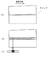
図4は、継手部にギャップが存在するワークに対して上述した実施の形態1に係るプラズマミグ溶接方法を適用したときのワーク及びビードの外観図である。同図(A)は溶接前のワークの外観を示し、継手部のギャップは溶接方向に対して前半部は0mmであり後半からは次第に大きくなる。同図(B)は溶接後のビード外観を示し、同図(C)はギャップ0mm部のビード断面を示す。同図は、溶接ワイヤにAl−Mg合金ワイヤ(A5356、1.2mm径)を使用し、母材に板厚6mmのAl−Mg合金板(A5052)を使用した場合である。図2に示すプラズマ電流の波形パラメータは、Iav=100A、Ip=150A、Ib=50A、Tp=Tbのときである。ミグアーク電流Iwaは100A(送給速度Fw=10m/分)であり、ミグアーク電圧Vwaは19Vであり、溶接速度は30cm/分のときである。
[Embodiment 2]
FIG. 4 is an external view of a workpiece and a bead when the plasma MIG welding method according to the first embodiment described above is applied to a workpiece having a gap in the joint portion. FIG. 2A shows the appearance of the workpiece before welding, and the gap of the joint portion is 0 mm in the first half with respect to the welding direction and gradually increases from the second half. FIG. 2B shows the appearance of the bead after welding, and FIG. This figure shows a case where an Al—Mg alloy wire (A5356, 1.2 mm diameter) is used as the welding wire and an Al—Mg alloy plate (A5052) having a plate thickness of 6 mm is used as the base material. The waveform parameters of the plasma current shown in FIG. 2 are when Iav = 100A, Ip = 150A, Ib = 50A, and Tp = Tb. The MIG arc current Iwa is 100 A (feeding speed Fw = 10 m / min), the MIG arc voltage Vwa is 19 V, and the welding speed is 30 cm / min.
ギャップが0mmの前半部はプラズマ電流の周波数を500Hzに設定し、同図(C)に示すように、十分な溶け込みを確保している。ギャップが大きくなる後半部は周波数を5Hzに設定し、ビード幅を広げてギャップ部における溶着金属の橋絡を確保して溶け落ちを防いでいる。 In the first half of the gap of 0 mm, the frequency of the plasma current is set to 500 Hz, and sufficient penetration is ensured as shown in FIG. In the latter half of the gap, the frequency is set to 5 Hz, and the bead width is widened to ensure a bridging of the weld metal in the gap to prevent burnout.
上述した実施の形態2によれば、ギャップのある継手に対するプラズマミグ溶接において、ギャップの大きさに応じてプラズマ電流の周波数を適正値に変化させることによって、適正なビード形状を得ることができる。 According to the second embodiment described above, an appropriate bead shape can be obtained by changing the frequency of the plasma current to an appropriate value in accordance with the size of the gap in plasma MIG welding for a joint having a gap.
1a 溶接ワイヤ
1b プラズマ電極
2 母材
3a ミグアーク
3b プラズマアーク
4 プラズマノズル
5 シールドノズル
6 送給ロール
f 周波数
Fc 送給制御信号
Fw 送給速度
Iav プラズマ電流の平均値
Ib ベース電流
Ip ピーク電流
Iwa ミグアーク電流
Iwb プラズマ電流
M 送給モータ
PSM ミグ溶接電源
PSP プラズマ溶接電源
Tb ベース期間
Tp ピーク期間
Vwa ミグアーク電圧
Claims (1)
前記プラズマアークに通電するプラズマ電流を予め定めた周波数でパルス状に変化させ、前記プラズマ電流の平均値を略一定値に維持したままで、継手部のギャップが第1の値であるときの前記周波数を前記ギャップが前記第1の値よりも大きな値の第2の値であるときの前記周波数よりも高く設定する、
ことを特徴とするプラズマミグ溶接方法。 A plasma arc is generated between the non-consumable plasma electrode and the base material, and the plasma electrode is formed in a hollow shape, and the insulated consumable electrode is fed through the hollow. In the plasma MIG welding method that welds by generating a MIG arc in between,
The plasma current to be supplied to the plasma arc is changed in a pulse shape at a predetermined frequency, and the average value of the plasma current is maintained at a substantially constant value, and the gap of the joint portion is the first value. Setting a frequency higher than the frequency when the gap is a second value greater than the first value;
The plasma MIG welding method characterized by the above-mentioned.
Priority Applications (1)
| Application Number | Priority Date | Filing Date | Title |
|---|---|---|---|
| JP2006262094A JP4890179B2 (en) | 2006-09-27 | 2006-09-27 | Plasma MIG welding method |
Applications Claiming Priority (1)
| Application Number | Priority Date | Filing Date | Title |
|---|---|---|---|
| JP2006262094A JP4890179B2 (en) | 2006-09-27 | 2006-09-27 | Plasma MIG welding method |
Publications (2)
| Publication Number | Publication Date |
|---|---|
| JP2008080355A JP2008080355A (en) | 2008-04-10 |
| JP4890179B2 true JP4890179B2 (en) | 2012-03-07 |
Family
ID=39351732
Family Applications (1)
| Application Number | Title | Priority Date | Filing Date |
|---|---|---|---|
| JP2006262094A Active JP4890179B2 (en) | 2006-09-27 | 2006-09-27 | Plasma MIG welding method |
Country Status (1)
| Country | Link |
|---|---|
| JP (1) | JP4890179B2 (en) |
Families Citing this family (5)
| Publication number | Priority date | Publication date | Assignee | Title |
|---|---|---|---|---|
| JP2010155251A (en) * | 2008-12-26 | 2010-07-15 | Daihen Corp | Plasma gma welding method |
| JP5410121B2 (en) * | 2009-03-10 | 2014-02-05 | 株式会社ダイヘン | Arc start control method for two-electrode arc welding |
| JP5557515B2 (en) * | 2009-12-08 | 2014-07-23 | 株式会社ダイヘン | Plasma MIG welding method |
| CN102126077B (en) * | 2010-01-12 | 2014-09-17 | 株式会社大亨 | Plasma metal inert gas arc welding method |
| JP5558881B2 (en) * | 2010-03-29 | 2014-07-23 | 株式会社ダイヘン | Plasma MIG welding method |
Family Cites Families (7)
| Publication number | Priority date | Publication date | Assignee | Title |
|---|---|---|---|---|
| JPS49119847A (en) * | 1973-03-19 | 1974-11-15 | ||
| JPH03477A (en) * | 1989-05-25 | 1991-01-07 | Toshiba Corp | Welding equipment utilizing combined heat sources |
| JP3004889B2 (en) * | 1995-03-06 | 2000-01-31 | 株式会社三社電機製作所 | Non-consumable electrode arc welding machine |
| JP3531889B2 (en) * | 1995-12-14 | 2004-05-31 | 日鐵溶接工業株式会社 | Swing type plasma torch |
| JP2001018067A (en) * | 1999-07-07 | 2001-01-23 | Hitachi Ltd | Method and device for narrow gap welding |
| JP3902419B2 (en) * | 2001-05-11 | 2007-04-04 | 株式会社日立製作所 | Arc welding method and arc welding apparatus |
| JP2005111539A (en) * | 2003-10-09 | 2005-04-28 | Daihen Corp | Plasma arc welding method |
-
2006
- 2006-09-27 JP JP2006262094A patent/JP4890179B2/en active Active
Also Published As
| Publication number | Publication date |
|---|---|
| JP2008080355A (en) | 2008-04-10 |
Similar Documents
| Publication | Publication Date | Title |
|---|---|---|
| JP3203668U (en) | Tandem hot wire system | |
| EP3126084B1 (en) | System and method of welding with use of ac welding waveform and enhanced consumable to improve welding of galvanized workpiece | |
| CA2858104C (en) | Dc electrode negative rotating arc welding method and system | |
| US9782850B2 (en) | Method and system to start and use combination filler wire feed and high intensity energy source for welding | |
| US9718147B2 (en) | Method and system to start and use combination filler wire feed and high intensity energy source for root pass welding of the inner diameter of clad pipe | |
| KR102134045B1 (en) | Adaptable rotating arc welding method and system | |
| US20130327749A1 (en) | Method and system to start and use combination filler wire feed and high intensity energy source for welding aluminum to steel | |
| US20110248007A1 (en) | Arc welding method and arc welding apparatus | |
| WO2014009800A2 (en) | Method and system to start and use combination filler wire feed and high intensity source for welding | |
| JP2009208137A (en) | Plasma mig welding method | |
| US20100012638A1 (en) | TIG Braze-Welding With Metal Transfer In Drops At A Controlled Frequency | |
| JPH11226730A (en) | Method and equipment for consumable electrode ac gas shield welding | |
| JP4890179B2 (en) | Plasma MIG welding method | |
| JP2008018436A (en) | Welding method and welded product | |
| JP2007237225A (en) | High-speed hot wire multi-electrode tig welding method of thin steel plate | |
| JP5410121B2 (en) | Arc start control method for two-electrode arc welding | |
| JP2012071334A (en) | Ac pulse arc welding control method | |
| JP4391877B2 (en) | Heat input control DC arc welding / pulse arc welding switching welding method | |
| JP2007237224A (en) | Tig welding method of thin steel plate | |
| JP7000790B2 (en) | MIG welding method and MIG welding equipment | |
| JP5557515B2 (en) | Plasma MIG welding method | |
| JP2011110604A (en) | Pulse arc welding method and welding apparatus | |
| JP2009166109A (en) | Crater treatment method of two-electrode arc welding | |
| WO2020202508A1 (en) | Mig welding method and mig welding device | |
| JP2004050228A (en) | Arc spot welding method and apparatus |
Legal Events
| Date | Code | Title | Description |
|---|---|---|---|
| A621 | Written request for application examination |
Free format text: JAPANESE INTERMEDIATE CODE: A621 Effective date: 20090826 |
|
| A977 | Report on retrieval |
Free format text: JAPANESE INTERMEDIATE CODE: A971007 Effective date: 20110616 |
|
| A131 | Notification of reasons for refusal |
Free format text: JAPANESE INTERMEDIATE CODE: A131 Effective date: 20110726 |
|
| A521 | Request for written amendment filed |
Free format text: JAPANESE INTERMEDIATE CODE: A523 Effective date: 20110831 |
|
| TRDD | Decision of grant or rejection written | ||
| A01 | Written decision to grant a patent or to grant a registration (utility model) |
Free format text: JAPANESE INTERMEDIATE CODE: A01 Effective date: 20111213 |
|
| A01 | Written decision to grant a patent or to grant a registration (utility model) |
Free format text: JAPANESE INTERMEDIATE CODE: A01 |
|
| A61 | First payment of annual fees (during grant procedure) |
Free format text: JAPANESE INTERMEDIATE CODE: A61 Effective date: 20111214 |
|
| R150 | Certificate of patent or registration of utility model |
Ref document number: 4890179 Country of ref document: JP Free format text: JAPANESE INTERMEDIATE CODE: R150 Free format text: JAPANESE INTERMEDIATE CODE: R150 |
|
| FPAY | Renewal fee payment (event date is renewal date of database) |
Free format text: PAYMENT UNTIL: 20141222 Year of fee payment: 3 |
|
| R250 | Receipt of annual fees |
Free format text: JAPANESE INTERMEDIATE CODE: R250 |
|
| R250 | Receipt of annual fees |
Free format text: JAPANESE INTERMEDIATE CODE: R250 |
|
| R250 | Receipt of annual fees |
Free format text: JAPANESE INTERMEDIATE CODE: R250 |
|
| R250 | Receipt of annual fees |
Free format text: JAPANESE INTERMEDIATE CODE: R250 |
|
| R250 | Receipt of annual fees |
Free format text: JAPANESE INTERMEDIATE CODE: R250 |
|
| R250 | Receipt of annual fees |
Free format text: JAPANESE INTERMEDIATE CODE: R250 |