JP4887346B2 - Semiconductor device - Google Patents
Semiconductor device Download PDFInfo
- Publication number
- JP4887346B2 JP4887346B2 JP2008297134A JP2008297134A JP4887346B2 JP 4887346 B2 JP4887346 B2 JP 4887346B2 JP 2008297134 A JP2008297134 A JP 2008297134A JP 2008297134 A JP2008297134 A JP 2008297134A JP 4887346 B2 JP4887346 B2 JP 4887346B2
- Authority
- JP
- Japan
- Prior art keywords
- island
- semiconductor device
- sealing resin
- semiconductor chip
- back surface
- Prior art date
- Legal status (The legal status is an assumption and is not a legal conclusion. Google has not performed a legal analysis and makes no representation as to the accuracy of the status listed.)
- Expired - Fee Related
Links
Images


Classifications
-
- H—ELECTRICITY
- H01—ELECTRIC ELEMENTS
- H01L—SEMICONDUCTOR DEVICES NOT COVERED BY CLASS H10
- H01L24/00—Arrangements for connecting or disconnecting semiconductor or solid-state bodies; Methods or apparatus related thereto
- H01L24/93—Batch processes
- H01L24/95—Batch processes at chip-level, i.e. with connecting carried out on a plurality of singulated devices, i.e. on diced chips
- H01L24/97—Batch processes at chip-level, i.e. with connecting carried out on a plurality of singulated devices, i.e. on diced chips the devices being connected to a common substrate, e.g. interposer, said common substrate being separable into individual assemblies after connecting
-
- H—ELECTRICITY
- H01—ELECTRIC ELEMENTS
- H01L—SEMICONDUCTOR DEVICES NOT COVERED BY CLASS H10
- H01L2224/00—Indexing scheme for arrangements for connecting or disconnecting semiconductor or solid-state bodies and methods related thereto as covered by H01L24/00
- H01L2224/01—Means for bonding being attached to, or being formed on, the surface to be connected, e.g. chip-to-package, die-attach, "first-level" interconnects; Manufacturing methods related thereto
- H01L2224/42—Wire connectors; Manufacturing methods related thereto
- H01L2224/44—Structure, shape, material or disposition of the wire connectors prior to the connecting process
- H01L2224/45—Structure, shape, material or disposition of the wire connectors prior to the connecting process of an individual wire connector
- H01L2224/45001—Core members of the connector
- H01L2224/45099—Material
- H01L2224/451—Material with a principal constituent of the material being a metal or a metalloid, e.g. boron (B), silicon (Si), germanium (Ge), arsenic (As), antimony (Sb), tellurium (Te) and polonium (Po), and alloys thereof
- H01L2224/45138—Material with a principal constituent of the material being a metal or a metalloid, e.g. boron (B), silicon (Si), germanium (Ge), arsenic (As), antimony (Sb), tellurium (Te) and polonium (Po), and alloys thereof the principal constituent melting at a temperature of greater than or equal to 950°C and less than 1550°C
- H01L2224/45144—Gold (Au) as principal constituent
-
- H—ELECTRICITY
- H01—ELECTRIC ELEMENTS
- H01L—SEMICONDUCTOR DEVICES NOT COVERED BY CLASS H10
- H01L2224/00—Indexing scheme for arrangements for connecting or disconnecting semiconductor or solid-state bodies and methods related thereto as covered by H01L24/00
- H01L2224/01—Means for bonding being attached to, or being formed on, the surface to be connected, e.g. chip-to-package, die-attach, "first-level" interconnects; Manufacturing methods related thereto
- H01L2224/42—Wire connectors; Manufacturing methods related thereto
- H01L2224/47—Structure, shape, material or disposition of the wire connectors after the connecting process
- H01L2224/48—Structure, shape, material or disposition of the wire connectors after the connecting process of an individual wire connector
- H01L2224/4805—Shape
- H01L2224/4809—Loop shape
- H01L2224/48091—Arched
-
- H—ELECTRICITY
- H01—ELECTRIC ELEMENTS
- H01L—SEMICONDUCTOR DEVICES NOT COVERED BY CLASS H10
- H01L2224/00—Indexing scheme for arrangements for connecting or disconnecting semiconductor or solid-state bodies and methods related thereto as covered by H01L24/00
- H01L2224/01—Means for bonding being attached to, or being formed on, the surface to be connected, e.g. chip-to-package, die-attach, "first-level" interconnects; Manufacturing methods related thereto
- H01L2224/42—Wire connectors; Manufacturing methods related thereto
- H01L2224/47—Structure, shape, material or disposition of the wire connectors after the connecting process
- H01L2224/48—Structure, shape, material or disposition of the wire connectors after the connecting process of an individual wire connector
- H01L2224/481—Disposition
- H01L2224/48151—Connecting between a semiconductor or solid-state body and an item not being a semiconductor or solid-state body, e.g. chip-to-substrate, chip-to-passive
- H01L2224/48221—Connecting between a semiconductor or solid-state body and an item not being a semiconductor or solid-state body, e.g. chip-to-substrate, chip-to-passive the body and the item being stacked
- H01L2224/48245—Connecting between a semiconductor or solid-state body and an item not being a semiconductor or solid-state body, e.g. chip-to-substrate, chip-to-passive the body and the item being stacked the item being metallic
- H01L2224/48247—Connecting between a semiconductor or solid-state body and an item not being a semiconductor or solid-state body, e.g. chip-to-substrate, chip-to-passive the body and the item being stacked the item being metallic connecting the wire to a bond pad of the item
-
- H—ELECTRICITY
- H01—ELECTRIC ELEMENTS
- H01L—SEMICONDUCTOR DEVICES NOT COVERED BY CLASS H10
- H01L2924/00—Indexing scheme for arrangements or methods for connecting or disconnecting semiconductor or solid-state bodies as covered by H01L24/00
- H01L2924/013—Alloys
- H01L2924/0132—Binary Alloys
- H01L2924/01322—Eutectic Alloys, i.e. obtained by a liquid transforming into two solid phases
-
- H—ELECTRICITY
- H01—ELECTRIC ELEMENTS
- H01L—SEMICONDUCTOR DEVICES NOT COVERED BY CLASS H10
- H01L2924/00—Indexing scheme for arrangements or methods for connecting or disconnecting semiconductor or solid-state bodies as covered by H01L24/00
- H01L2924/10—Details of semiconductor or other solid state devices to be connected
- H01L2924/11—Device type
- H01L2924/13—Discrete devices, e.g. 3 terminal devices
- H01L2924/1304—Transistor
- H01L2924/1305—Bipolar Junction Transistor [BJT]
- H01L2924/13055—Insulated gate bipolar transistor [IGBT]
-
- H—ELECTRICITY
- H01—ELECTRIC ELEMENTS
- H01L—SEMICONDUCTOR DEVICES NOT COVERED BY CLASS H10
- H01L2924/00—Indexing scheme for arrangements or methods for connecting or disconnecting semiconductor or solid-state bodies as covered by H01L24/00
- H01L2924/10—Details of semiconductor or other solid state devices to be connected
- H01L2924/11—Device type
- H01L2924/13—Discrete devices, e.g. 3 terminal devices
- H01L2924/1304—Transistor
- H01L2924/1306—Field-effect transistor [FET]
- H01L2924/13091—Metal-Oxide-Semiconductor Field-Effect Transistor [MOSFET]
-
- H—ELECTRICITY
- H01—ELECTRIC ELEMENTS
- H01L—SEMICONDUCTOR DEVICES NOT COVERED BY CLASS H10
- H01L2924/00—Indexing scheme for arrangements or methods for connecting or disconnecting semiconductor or solid-state bodies as covered by H01L24/00
- H01L2924/10—Details of semiconductor or other solid state devices to be connected
- H01L2924/11—Device type
- H01L2924/14—Integrated circuits
Abstract
Description
本発明は半導体装置に関するものである。 The present invention relates to a semiconductor device.
IC、ディスクリート素子等の半導体素子を製造する際には、図10(A)に示すような封止技術が主に用いられる。即ち、半導体チップ1をアイランド2上に実装(ダイボンド)し、半導体チップ1の周辺に配置したリード端子3とトランジスタ素子のベース電極、エミッタ電極とをそれぞれボンディングワイヤー4で電気的に接続(ワイヤボンド)し、半導体チップ1をエポキシ樹脂等の熱硬化型樹脂4によるトランスファーモールドによって、半導体チップ1とリード端子3の一部を完全に被覆保護したものである。樹脂5の外部に導出されたリード端子3はZ字型に折り曲げられて表面実装用途に適したものとしてある。
When manufacturing a semiconductor element such as an IC or a discrete element, a sealing technique as shown in FIG. 10A is mainly used. That is, the semiconductor chip 1 is mounted on the island 2 (die bonding), and the
例えばNPN型トランジスタ素子を形成した半導体チップ1を封止した場合は、アイランド2をコレクタ電極として3端子構造の半導体装置が提供される。尚、6は半導体チップ1を固着するための半田などの接着剤である。
For example, when the semiconductor chip 1 on which the NPN transistor element is formed is sealed, a semiconductor device having a three-terminal structure is provided using the
上記の半導体装置の製造工程にあっては、アイランド2とリード端子3は、銅素材または鉄素材からなるフープ状あるいは短冊状のリードフレームの状態で供給され、該リードフレームには例えば半導体装置20個分のアイランド2とリード端子3が形成されている。
In the manufacturing process of the semiconductor device described above, the
また、上記の製造工程のトランスファーモールドにあっては、図10(B)を参照して、上金型7及び下金型8によって個々の半導体装置の外形形状に合致した空間であるキャビティ9を構成し、該キャビティの内部にダイボンド及びワイヤボンドを施したリードフレームを設置し、この状態でキャビティ9内に樹脂を注入することによりトランスファーモールドが行われる。更に、樹脂封止した後に前記リードフレームからリード部分他を切断することで半導体装置を個々の素子に分離している。
Further, in the transfer mold of the above manufacturing process, referring to FIG. 10B, a cavity 9 which is a space matching the outer shape of each semiconductor device is formed by the
第1の課題:
樹脂モールドされた半導体装置は、通常、ガラスエポキシ基板等のプリント基板に実装され、同じくプリント基板上に実装された他の素子と電気的に接続することにより、所望の回路網を構成する。この時、リード端子3が樹脂5の外部に導出された半導体装置では、リード端子3の先端から先端までの距離10(図10(B)図示)を実装面積として占有するので、実装面積が大きいという欠点がある。
First issue:
The resin-molded semiconductor device is usually mounted on a printed board such as a glass epoxy board, and is electrically connected to other elements mounted on the printed board to constitute a desired circuit network. At this time, in the semiconductor device in which the
第2の課題:
金型内に設置したときのリードフレームとキャビティ9との位置合わせ精度はプラス・マイナス50μ程度が限界である。このため、アイランド2の大きさは前記合わせ精度を考慮した大きさに設計しなければならない。従って、合わせ精度の問題は、パッケージの外形寸法に対するアイランド2の寸法を小さくし、これがパッケージの外形寸法に対して収納可能な半導体チップ1の最大寸法に制限を与えていた。
Second issue:
The alignment accuracy between the lead frame and the cavity 9 when installed in the mold is limited to about plus or minus 50 μm. For this reason, the size of the
第3の課題:
半導体装置を実装基板上に実装するときは、前記実装基板上に形成したプリント配線とリード端子3とを半田で固着するが、この時半田がどの程度まで盛り上がるか(半田フィレットがどこまで盛り上がるか)によって半導体装置の固着強度が大きく左右される。半導体装置を微細化した場合であっても、この固着強度は維持しなければならないという課題がある。
Third issue:
When a semiconductor device is mounted on a mounting board, the printed wiring formed on the mounting board and the
本発明は、以下の構成で解決するものである。つまり
お互いが対向する第1の側辺および第2の側辺と、および前記第1の側辺および第2の側辺と角部を成し、お互いが対向する第3の側辺および第4の側辺から成るCuを主材料とした矩形のアイランドと、
前記第1の側辺および前記第2の側辺に設けられ、前記アイランドと一体で同一材料から成る第1の突起部および第2の突起部と、
前記第3の側辺から前記アイランドと一体で同一材料から成る第3の突起部と、
前記第4の側辺に一端が近接して設けられたCuを主材料とする複数のリード端子と、
前記アイランドに電気的に接続されて設けられた半導体チップと、
前記半導体チップ表面に設けられた電極と前記リード端子とを電気的に接続する金属細線と、
前記アイランド、前記第1〜第3の突起部、前記半導体チップ、前記複数のリード端子を封止し、表面、前記表面と対向する裏面、前記表面と前記裏面の周囲から延在する4側面から成る6面体の封止樹脂と、
前記封止樹脂の側面には、前記第1〜第3の突起部および前記複数のリードが延在して成る半導体装置をもって解決するものである。
The present invention solves the following configuration. That is, the first side and the second side that face each other, and the third side and the fourth side that form a corner with the first side and the second side and that face each other. A rectangular island made mainly of Cu consisting of the sides of
A first protrusion and a second protrusion, which are provided on the first side and the second side, and are made of the same material as the island;
A third protrusion made of the same material integrally with the island from the third side;
A plurality of lead terminals mainly composed of Cu provided at one end close to the fourth side;
A semiconductor chip provided in electrical connection with the island;
A thin metal wire that electrically connects the electrode provided on the surface of the semiconductor chip and the lead terminal;
Sealing the island, the first to third protrusions, the semiconductor chip, and the plurality of lead terminals, from the front surface, the back surface facing the front surface, and the four side surfaces extending from the periphery of the front surface and the back surface A hexahedral sealing resin comprising:
The problem is solved by a semiconductor device in which the first to third protrusions and the plurality of leads extend on the side surface of the sealing resin.
本発明によれば、リード端子34がパッケージから突出しない半導体装置を得ることができる。従って、半導体装置を実装したときのデッドスペースを削減し、高密度実装に適した半導体装置を得ることができる。
According to the present invention, a semiconductor device in which the
以下に本発明の製造方法を詳細に説明する。 The production method of the present invention will be described in detail below.
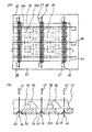
第1工程:(図1)
先ず、リードフレーム30を準備する。図1(A)はリードフレーム30の平面図であり、図1(B)は図1(A)のAA断面図である。
First step: (Fig. 1)
First, the
本発明で用いられるリードフレーム30は、半導体チップを搭載するための多数の素子搭載部31、31A・・・が行・列方向(又はそれらの一方方向にのみ)に複数個繰り返しパターンで配置されており、該多数個の素子搭載部31は、それらの周囲を取り囲む様に配置した枠体部32によって保持されている。
In the
素子搭載部31は、半導体チップを固着するアイランド33と、外部接続用電極となる複数のリード端子34を少なくとも具備する。アイランド33は連結バー35によって互いに連結され、同じく連結バー35によって枠体部32に連結されている。リード端子34はアイランド33に連結されている。この時、特定のアイランド33に対しては、その隣に隣接するアイランド33Aに連結保持されたリード端子34が対応して1つの素子搭載部31を構成する。アイランド33とリード端子34との連結部分近傍のリード端子34には、部分的に線幅を細く加工した凹部36を形成している。この様に素子搭載部31を行・列方向に複数配置することで、1本の短冊状のリードフレーム30に例えば100個の素子搭載部31を配置する。
The
素子搭載部31群を取り囲む枠体部32には、複数個の合わせマーク37を形成する。合わせマーク37は、貫通孔またはスタンピングによって部分的に凹ませたもの等、製造工程における自動認識機能が働くものであればよい。また、形状も正方形、長方形、矩形、円形等があげられる。そして、素子搭載部31毎に1個、または複数個毎に1個等間隔で配置する。
A plurality of
上記のリードフレーム30は、例えば、約0.2mm厚の銅系の金属材料で形成された帯状あるいは矩形状のリードフレーム用金属薄板を用意し、このリードフレーム用金属薄板をエッチング加工またはスタンピング加工によって図示したパターンに開口することにより得ることができる。尚、リードフレーム30の板厚は必要に応じて適宜に設定することができる。
The
第2工程:(図2)
次に、リードフレーム30に対してダイボンド工程とワイヤボンド工程を行う。図2(B)は図2(A)のAA線断面図である。
Second step: (FIG. 2)
Next, a die bonding process and a wire bonding process are performed on the
各アイランド33、33Aの一主面上にAgペースト、半田等の導電ペースト38を塗布し、その導電ペースト38を介して各アイランド33、33A上に半導体チップ39を固着する。各アイランド表面に金メッキを行い、そのメッキ上に半導体チップを共晶接続することも可能である。
A
更に、半導体チップ39の表面に形成されたボンディングパッドと、これに対応するリード端子34とをワイヤ40でワイヤボンディングする。ワイヤ40は例えば直径が20μの金線から成る。ここで、ワイヤ40は各アイランド33上に固着した半導体チップ39の表面電極と、その隣に隣接した他のアイランド33Aから延在するリード端子34とを接続する。
Further, the bonding pads formed on the surface of the
半導体チップ39が固着されたアイランド33の裏面は、係る半導体チップ39の外部接続用の電極として用いることができる。アイランド33の裏面を接続用端子の1つとして用いる形態は、半導体チップ39として例えばトランジスタ、パワーMOSFET等の、電流経路が垂直方向になる半導体デバイス素子に適している。
The back surface of the
半導体チップ39を固着するために塗布した導電性ペースト38は、図2(A)から明らかなように、半導体チップ39が固着されるアイランド33上に選択的に塗布形成する。リード端子34上に導電性ペースト38が付着すると、ワイヤボンディングを行う場合に、ボンディング装置のキャピラリーの先端部分に導電性ペーストがつまりボンディング不良が生じ生産性が低下する恐れがあるためである。この様な問題がない場合には、導電性ペーストを素子搭載部31全面に塗布しても良い。
The
第3工程:(図3)
次に、全体を樹脂モールドする。図3(B)は図3(A)のAA線断面図である。
Third step: (Fig. 3)
Next, the whole is resin-molded. FIG. 3B is a cross-sectional view taken along line AA in FIG.
リードフレーム30上にエポキシ樹脂等の熱硬化性の封止用樹脂層41を形成し、各素子搭載部31、31A・・・、半導体チップ39及びワイヤ40を封止保護する。樹脂41は、各半導体チップ39・・・を個別にパッケージングするものではなく、全ての半導体チップ39を共通に被うように形成する。また、リードフレーム30の裏面側にも0.05mm程度の厚みで樹脂41を被着する。これで、アイランド33とリード端子34は完全に樹脂41内部に埋設されることになる。
A thermosetting
この樹脂層41は、射出成形用の上下金型が形成する空間(キャビティ)内にリードフレーム30を設置し、該空間内にエポキシ樹脂を充填、成形する事によって形成する。あるいは、枠体32に高さ数mm、幅数mmの環状のダムを形成しておき、該ダムで囲まれた領域を満たすように液状の樹脂を充填し、これを熱処理で硬化したものであっても良い。
The
第4工程:(図4)
次に、リードフレーム30の裏面側の樹脂41を部分的に除去してスリット孔42を形成する。図4(B)は図4(A)のAA線断面図である。
Fourth step: (FIG. 4)
Next, the
スリット孔41は、後で外部接続端子を構成する為に形成するものである。約0.5mmの幅を有し、ダイシング装置のブレードによって樹脂42を切削することにより形成した。前記ブレードには様々な板厚のものが準備されており、用いるブレードの板厚に応じて、1回であるいは複数回繰り返すことで所望の幅に形成する。この時、樹脂41を切削すると同時にリード端子34の裏面側も約0.05mm程切削して、リードフレーム30の金属表面を露出させる。このスリット孔42は、各リード端子34にくさび状に形成した「凹部36」の付近に形成する。この時、凹部36は樹脂41で被覆されて目視できないので、あらかじめ形成した合わせマーク37を位置基準として用いる。
The
第5工程:(図5(A))
第4工程で形成したスリット孔42に沿って、第2のスリット孔42aを形成する。
Fifth step: (FIG. 5A)
A
第2のスリット孔42aの形成には、例えば切削面が山形の形状を持つ、板厚が0.4mm程度のダイシングブレード43を用い、スリット孔42から更に0.1mm程度深く掘り下げることによって第2のスリット孔42aの断面形状をV字型に形成する。
The
第2のスリット孔42aの形成に用いたダイシングブレード43が端面山形の形状を持つのに対し、スリット孔42の形成には端面が直角の平坦面をもつものを用いた。平坦面のダイシングブレードは、山形のものよりは摩耗による寿命を長くすることができる。この様にダイシングを2回に分けることで、摩耗の激しい山形のダイシングブレード43の消耗を低減している。尚、断面形状はU字型でも良い。また、1回のダイシング工程でV字型の第2のスリット孔42aを直接形成しても良い。更に、板厚の薄いダイシングブレードを用い、少なくとも3回のダイシング工程で1本のスリット孔42を形成すると共に、スリット孔42の中心部で切削深さを深くするような制御を行って大略V字型またはU字型の溝を形成してもよい。更に、選択なエッチング加工によっても形成が可能である。この様に第2のスリット孔42aをV字型またはU字型に形成することによって、スリット孔42aの側壁を傾斜させることができる。
The
第6工程:(図5(B))
スリット孔42、42aを形成したことにより露出させたリード端子34の表面に半田メッキ等のメッキ層45を形成する。このメッキ層45は、リードフレーム30を電極の一方とする電解メッキ法により行われる。スリット孔42、42aはリード端子34の板厚の全部を切断していないので、アイランド33とリード端子34は未だ電気的な導通が保たれている。更に各アイランド33が連結バー35によって枠体32に共通接続されている。このように露出した金属表面のすべてが電気的に導通しているので、一回のメッキ工程でメッキ層45を形成することができる。
Sixth step: (FIG. 5B)
A
第7工程:(図6)
次に、素子搭載部31毎に樹脂層41を切断して各々の素子A、素子B、素子C・・・を分離する。即ち、アイランド33とこの上に固着された半導体チップ39に接続されたリード端子34を囲む領域(同図の切断ライン46)で切断することにより、素子搭載部31毎に分割した半導体装置を形成する。切断にはダイシング装置が用いられ、ダイシング装置のブレード47によって樹脂層41とリードフレーム30とを同時に切断する。スリット孔42が位置する箇所では、少なくともスリット孔42aの傾斜した側壁に付着したメッキ層45を残すように形成する。この様に残存させたメッキ層45は、半導体装置をプリント基板上に実装する際に利用される。また、切断したリード端子34の他方はア
イランド33に連続する突起部33aとして残存し、切断した連結バー35はアイランド33に連続する突起部33bとして残存する。切断されたリード端子34及び突起部33a、33bの切断面は、樹脂層41の切断面と同一平面を形成し、該同一平面に露出する。ダイシング工程においては裏面側(スリット孔42を設けた側)にブルーシート(たとえば、商品名:UVシート、リンテック株式会社製)を貼り付け、前記ダイシングブレード47がブルーシートの表面に到達するような切削深さで切断する。この時に、あらかじめ形成した合わせマーク37をダイシング装置側で自動認識し、これを位置基準として用いてダイシングする。本実施の形態では、合わせマーク37を長方形の形状とし、該長方形の長辺を基準位置とした。更に、ダイシングブレードの板厚は第2のスリット孔42aの幅よりも薄い(例えば、幅0.1mm)ものを用い、スリット孔42の中心線に沿って、ダイシングブレード47がリード端子33の凹部36上を通過するようにダイシングした。これで、切断後のリード端子33の先端部が先細りの形状となり、樹脂41から容易には抜け落ちない形状に加工できる。
Step 7: (FIG. 6)
Next, the
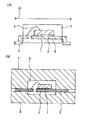
図7は斯かる製造方法によって形成した完成後の半導体装置を示す、(A)側面図、(B)裏面図、(C)側面図である。 FIG. 7A is a side view, FIG. 7B is a back view, and FIG. 7C is a side view showing a completed semiconductor device formed by such a manufacturing method.
半導体チップ39とボンディングワイヤ40を含めて、アイランド33とリード端子34が樹脂41でモールドされて、大略直方体のパッケージ形状を形成する。樹脂41は熱硬化性エポキシ樹脂である。アイランド33とリード端子34は、厚さが約0.2mmの銅系の金属材料から成る。樹脂41の外形寸法は、縦×横×高さが、約0.7mm×1.0mm×0.6mmである。
The
直方体のパッケージ外形を形成する6面のうち、少なくとも側面41a、41b、41c、41dは樹脂41を切断した(第7工程参照)切断面で構成される。該切断面に沿ってリード端子34の切断面が露出する。アイランド33には切断されたリード端子34の名残である突起部33aと連結部35の名残である突起部33bを有し、これらの突起部33a、33bの切断面も露出する。
Of the six surfaces forming the package shape of the rectangular parallelepiped, at least the side surfaces 41a, 41b, 41c and 41d are constituted by cut surfaces obtained by cutting the resin 41 (see the seventh step). A cut surface of the
図8は斯かる装置を裏面側からみたときの斜視図である。側面41b、41dの裏面側には第4、第5工程で形成したスリット孔42、42aの名残である段差部48を有し、該段差部48の表面にアイランド33の突出部33aの裏面側と、リード端子34の裏面側の一部が露出する。リード端子34の先端は、スリット孔42aの側壁が残ることによって傾斜している。更に、段差部48に露出したアイランド33とリード端子34の表面は第6工程で形成した金属メッキ層45で被覆される。尚、リード端子34の露出部分とアイランド33の露出部との間は、樹脂41で被覆される。
FIG. 8 is a perspective view of such a device as viewed from the back side. On the back surface side of the side surfaces 41b and 41d, there is a stepped
この装置をプリント基板上に実装した状態の断面図を図9に示す。実装基板24上に形成した素子間接続用のプリント配線25に対して段差部48に露出したリード端子34とアイランド33の突起部33aとを位置合わせし、半田26等によって両者を接続する。この時、リード端子34の先端にはスリット孔42、42aの側壁に対応する部分まで上記の第6工程で形成した金属メッキ層45が形成されており、これが半田の濡れ性を良好にし、半田26を高く盛り上げて半田フィレットを形成する。第7工程で切断した部分のリード端子34端面にはメッキ層45が被覆しないので、そこまでは半田が盛り上がらない。
FIG. 9 shows a cross-sectional view of the device mounted on a printed circuit board. The
以上の方法によって製造された半導体装置は、以下のメリットを有する。 The semiconductor device manufactured by the above method has the following merits.
本発明の製造方法によって製造した半導体装置は、金属製リード端子がパッケージから突出しないので、実装面積を半導体装置の大きさと同じ程度の大きさにすることができる。従って、半導体装置の実装面積に対する能動部分(半導体チップ39のチップサイズを意味する)の比である実装有効面積を、図10に示したものに比べて大幅に向上できる。これにより、実装基板上に実装したときの実装面積のデッドスペースを小さくすることができ、実装基板の小型化に寄与することができる。 In the semiconductor device manufactured by the manufacturing method of the present invention, the metal lead terminals do not protrude from the package, so that the mounting area can be made as large as the size of the semiconductor device. Therefore, the mounting effective area, which is the ratio of the active portion (meaning the chip size of the semiconductor chip 39) to the mounting area of the semiconductor device, can be significantly improved as compared with that shown in FIG. Thereby, the dead space of the mounting area when mounted on the mounting substrate can be reduced, which can contribute to the downsizing of the mounting substrate.
分割された半導体装置の各外部接続用電極の表面には、スリット孔42、42aを設けたことによりメッキ層45が残されているので、実装基板上に半田固着した際に該半田26が切断面の上部まで(スリット孔42、42aの側壁に相当する部分)容易に盛り上がって半田フィレットを形成する。従って半田接合力が向上し熱ストレス等の応力による劣化を防止することができる。また、端面が傾斜していることにより、半田26が回り込みやすい構造であり、これも接着強度を上げる効果がある。
Since the plated
この装置のアイランド33や外部接続用リード端子34は、段差部48に露出し、段差部48と段差部48との間の領域は樹脂41によって被覆されるので露出しない。従って実装基板24上に実装した際に半田26と半田26との距離を比較的大きく設計でき、半田ブリッジによる外部接続端子間の短絡事故を防止できる。
The
分割された半導体装置のリード端子34の終端は、図7(B)に示すように、半導体装置の終端付近で先細りに形成されるために、リード端子34が樹脂層41の側面から抜け落ちることを防止している。尚くさび形状以外にも、コの字型に凹ませた形状でも良い。
The terminal end of the
多数個の素子をまとめてパッケージングするので、個々にパッケージングする場合に比べて無駄にする材料を少なくでき。材料費の低減につながる。 Since many devices are packaged together, less material is wasted compared to individual packaging. It leads to reduction of material cost.
パッケージの外形をダイシング装置のブレードで切断することにより構成したので、リードフレーム30のパターンに対する樹脂41外形の位置あわせ精度を向上できる。即ち、トランスファーモールド技術によるモールド金型とリードフレーム30との合わせ精度がプラス・マイナス50μ程度であるのに対して、ダイシング装置によるダイシングブレードとリードフレーム30との合わせ精度はプラス・マイナス10μ程度に小さくできる。合わせ精度を小さくできることは、アイランド33の面積を増大して、搭載可能な半導体チップ39のチップ面積を増大できることを意味し、これも上記有効実装面積効率を向上させる。この時、あらかじめリードフレーム30の外枠32に位置あわせマーク37を形成しておき、該マーク37を使用してダイシングを行うことにより、上記ダイシング装置の合わせ精度を活用でき、樹脂41外形とアイランド33などとの間隔を狭めることができるのである。
Since the outer shape of the package is cut by the blade of the dicing apparatus, the alignment accuracy of the outer shape of the
尚、上述した実施形態では、3端子用のリードフレームを用いて説明をしたが、リード端子を3本以上具備するような装置にも適用が可能である。 In the above-described embodiment, the description has been given using the lead frame for three terminals, but the present invention can be applied to an apparatus having three or more lead terminals.
また、上述した実施形態では、各アイランドに1つの半導体チップ39を固着したが、1つのアイランドに、例えばトランジスタを複数個固着すること、及び、トタンジスタと縦型パワーMOSFET等の他の素子との複合固着も可能である。
In the above-described embodiment, one
さらに、本実施形態では、半導体チップ39にトランジスタを形成したが、例えば、パワーMOSFET、IGBT、HBT等のデバイスを形成した半導体チップであっても、本発明に応用できることは説明するまでもない。加えて、リード端子の本数を増大することでBIP、MOS型等の集積回路等にも応用することができる。
Furthermore, in the present embodiment, the transistor is formed on the
以上説明したように、本発明によれば、リード端子34がパッケージから突出しない半導体装置を得ることができる。従って、半導体装置を実装したときのデッドスペースを削減し、高密度実装に適した半導体装置を得ることができる。
As described above, according to the present invention, a semiconductor device in which the
外部接続端子と外部接続端子との間を樹脂層41で被覆した構造にできるので、装置を実装したときの半田ブリッジ等による端子間短絡の事故を防止できる。
Since the external connection terminal and the external connection terminal are covered with the
パッケージの外形をダイシングブレードによる切断面で構成することにより、アイランド33と樹脂41の端面との寸法精度を向上できる。従って、アイランド33の面積を増大して、収納可能な半導体チップ39のチップサイズを増大できる。
By configuring the outer shape of the package with a cut surface by a dicing blade, the dimensional accuracy between the
リードフレーム30のパターン全体を樹脂41で埋設したにもかかわらず、あらかじめ枠体32に合わせマーク37を形成しておき、これを位置基準としてダイシングするようにしたので、ダイシング装置の合わせ精度を最大限に活用することができる。
Even though the entire pattern of the
ダイシングで切断するリード端子に、あらかじめV字型またはU字型のスリット孔42aを形成し、この表面に金属メッキ層45を形成して、切断後も金属メッキ層45を残すようにしたので、実装時に半田26がリード端子34の端部で容易に盛り上がり、これが半導体装置の固着強度を増大する。
Since the V-shaped or
Claims (5)
前記第1の側辺および第2の側辺に設けられ、前記アイランドと一体で同一材料から成る第1の突起部および第2の突起部と、
前記第3の側辺から前記アイランドと一体で同一材料から成る第3の突起部と、
前記第4の側辺に一端が近接して設けられたCuを主材料とする複数のリード端子と、
前記アイランドに電気的に接続されて設けられた半導体チップと、
前記半導体チップ表面に設けられた電極と前記リード端子とを電気的に接続する金属細線と、
前記アイランド、前記第1〜第3の突起部、前記半導体チップ、前記複数のリード端子を封止し、表面、前記表面と対向する裏面、前記表面と前記裏面の周囲から延在する4側面から成る6面体の封止樹脂と、
前記封止樹脂の側面に、前記第1〜第3の突起部および前記複数のリード端子が延在され、前記アイランドは、前記封止樹脂の側面から内側に後退して成り、
前記第3の突起部及び前記リード端子は、前記封止樹脂の裏面から露出することなく、
前記封止樹脂は、前記第3の突起部が延在する前記側面と前記裏面との間であり、前記裏面に対して前記表面側に傾斜する第1の傾斜面と、前記リード端子が延在する前記側面と前記裏面との間であり、前記裏面に対して前記表面側に傾斜する第2の傾斜面とを有し、
前記第1の傾斜面から露出する前記第3の突起部及び前記第2の傾斜面から露出する前記リード端子にはメッキ層が形成される事を特徴とした半導体装置。 The first side and the second side opposite to each other, and the first side and the second side to form a corner, and the third side and the fourth side opposite to each other. A rectangular island with Cu as the main material on the side,
A first protrusion and a second protrusion, which are provided on the first side and the second side, and are made of the same material integrally with the island;
A third protrusion made of the same material integrally with the island from the third side;
A plurality of lead terminals mainly composed of Cu provided at one end close to the fourth side;
A semiconductor chip provided in electrical connection with the island;
A thin metal wire that electrically connects the electrode provided on the surface of the semiconductor chip and the lead terminal;
Sealing the island, the first to third protrusions, the semiconductor chip, and the plurality of lead terminals, from the front surface, the back surface facing the front surface, and the four side surfaces extending from the periphery of the front surface and the back surface A hexahedral sealing resin comprising:
A side surface of the sealing resin, the first to third projections and said plurality of lead terminals extend, said islands, Ri formed by recessed inward from the side surface of the sealing resin,
The third protrusion and the lead terminal are not exposed from the back surface of the sealing resin,
The sealing resin is between the side surface on which the third protrusion extends and the back surface, the first inclined surface is inclined to the front surface side with respect to the back surface, and the lead terminal extends. A second inclined surface that is between the side surface and the back surface, and is inclined to the front surface side with respect to the back surface;
A semiconductor device, wherein a plating layer is formed on the third protrusion exposed from the first inclined surface and the lead terminal exposed from the second inclined surface .
Priority Applications (1)
| Application Number | Priority Date | Filing Date | Title |
|---|---|---|---|
| JP2008297134A JP4887346B2 (en) | 2008-11-20 | 2008-11-20 | Semiconductor device |
Applications Claiming Priority (1)
| Application Number | Priority Date | Filing Date | Title |
|---|---|---|---|
| JP2008297134A JP4887346B2 (en) | 2008-11-20 | 2008-11-20 | Semiconductor device |
Related Parent Applications (1)
| Application Number | Title | Priority Date | Filing Date |
|---|---|---|---|
| JP2006243624A Division JP4383436B2 (en) | 2006-09-08 | 2006-09-08 | Semiconductor device |
Publications (3)
| Publication Number | Publication Date |
|---|---|
| JP2009049435A JP2009049435A (en) | 2009-03-05 |
| JP2009049435A5 JP2009049435A5 (en) | 2010-04-30 |
| JP4887346B2 true JP4887346B2 (en) | 2012-02-29 |
Family
ID=40501297
Family Applications (1)
| Application Number | Title | Priority Date | Filing Date |
|---|---|---|---|
| JP2008297134A Expired - Fee Related JP4887346B2 (en) | 2008-11-20 | 2008-11-20 | Semiconductor device |
Country Status (1)
| Country | Link |
|---|---|
| JP (1) | JP4887346B2 (en) |
Families Citing this family (2)
| Publication number | Priority date | Publication date | Assignee | Title |
|---|---|---|---|---|
| JP6752639B2 (en) | 2016-05-02 | 2020-09-09 | ローム株式会社 | Manufacturing method of semiconductor devices |
| US10388616B2 (en) | 2016-05-02 | 2019-08-20 | Rohm Co., Ltd. | Semiconductor device and method for manufacturing the same |
Family Cites Families (4)
| Publication number | Priority date | Publication date | Assignee | Title |
|---|---|---|---|---|
| JPS62150868A (en) * | 1985-12-25 | 1987-07-04 | Hitachi Micro Comput Eng Ltd | Lead frame for semiconductor device and resin sealing method using same |
| JP3304705B2 (en) * | 1995-09-19 | 2002-07-22 | セイコーエプソン株式会社 | Manufacturing method of chip carrier |
| JP3209696B2 (en) * | 1996-03-07 | 2001-09-17 | 松下電器産業株式会社 | Electronic component manufacturing method |
| JP3877402B2 (en) * | 1997-11-28 | 2007-02-07 | 三洋電機株式会社 | Manufacturing method of semiconductor device |
-
2008
- 2008-11-20 JP JP2008297134A patent/JP4887346B2/en not_active Expired - Fee Related
Also Published As
| Publication number | Publication date |
|---|---|
| JP2009049435A (en) | 2009-03-05 |
Similar Documents
| Publication | Publication Date | Title |
|---|---|---|
| US11145582B2 (en) | Method of manufacturing semiconductor devices with a paddle and electrically conductive clip connected to a leadframe and corresponding semiconductor device | |
| JP3819574B2 (en) | Manufacturing method of semiconductor device | |
| JP3877401B2 (en) | Manufacturing method of semiconductor device | |
| US6498392B2 (en) | Semiconductor devices having different package sizes made by using common parts | |
| JP4614586B2 (en) | Method for manufacturing hybrid integrated circuit device | |
| JP4417150B2 (en) | Semiconductor device | |
| US8592962B2 (en) | Semiconductor device packages with protective layer and related methods | |
| JP3877409B2 (en) | Manufacturing method of semiconductor device | |
| US20130017652A1 (en) | Method of manufacturing a semiconductor device package with a heatsink | |
| JP3877410B2 (en) | Manufacturing method of semiconductor device | |
| JP4784945B2 (en) | Manufacturing method of semiconductor device | |
| JP3877405B2 (en) | Manufacturing method of semiconductor device | |
| JP3877402B2 (en) | Manufacturing method of semiconductor device | |
| JP4887346B2 (en) | Semiconductor device | |
| JP3831504B2 (en) | Lead frame | |
| JP4987041B2 (en) | Manufacturing method of semiconductor device | |
| JPH11307673A (en) | Semiconductor device and manufacture thereof | |
| JP5086315B2 (en) | Manufacturing method of semiconductor device | |
| US11710684B2 (en) | Package with separate substrate sections | |
| JP2006279088A (en) | Method for manufacturing semiconductor device | |
| JP4383436B2 (en) | Semiconductor device | |
| WO2022202242A1 (en) | Semiconductor device and manufacturing method for semiconductor device | |
| JP5121807B2 (en) | Manufacturing method of semiconductor device | |
| JP4723776B2 (en) | Manufacturing method of semiconductor device | |
| JP4207671B2 (en) | Manufacturing method of semiconductor package |
Legal Events
| Date | Code | Title | Description |
|---|---|---|---|
| A621 | Written request for application examination |
Free format text: JAPANESE INTERMEDIATE CODE: A621 Effective date: 20081212 |
|
| A521 | Written amendment |
Free format text: JAPANESE INTERMEDIATE CODE: A523 Effective date: 20100311 |
|
| A711 | Notification of change in applicant |
Free format text: JAPANESE INTERMEDIATE CODE: A711 Effective date: 20110530 |
|
| A131 | Notification of reasons for refusal |
Free format text: JAPANESE INTERMEDIATE CODE: A131 Effective date: 20110801 |
|
| A521 | Written amendment |
Free format text: JAPANESE INTERMEDIATE CODE: A523 Effective date: 20111027 |
|
| TRDD | Decision of grant or rejection written | ||
| A01 | Written decision to grant a patent or to grant a registration (utility model) |
Free format text: JAPANESE INTERMEDIATE CODE: A01 Effective date: 20111205 |
|
| A01 | Written decision to grant a patent or to grant a registration (utility model) |
Free format text: JAPANESE INTERMEDIATE CODE: A01 |
|
| A61 | First payment of annual fees (during grant procedure) |
Free format text: JAPANESE INTERMEDIATE CODE: A61 Effective date: 20111212 |
|
| FPAY | Renewal fee payment (event date is renewal date of database) |
Free format text: PAYMENT UNTIL: 20141216 Year of fee payment: 3 |
|
| R150 | Certificate of patent or registration of utility model |
Free format text: JAPANESE INTERMEDIATE CODE: R150 |
|
| FPAY | Renewal fee payment (event date is renewal date of database) |
Free format text: PAYMENT UNTIL: 20141216 Year of fee payment: 3 |
|
| S111 | Request for change of ownership or part of ownership |
Free format text: JAPANESE INTERMEDIATE CODE: R313113 |
|
| FPAY | Renewal fee payment (event date is renewal date of database) |
Free format text: PAYMENT UNTIL: 20141216 Year of fee payment: 3 |
|
| R360 | Written notification for declining of transfer of rights |
Free format text: JAPANESE INTERMEDIATE CODE: R360 |
|
| R360 | Written notification for declining of transfer of rights |
Free format text: JAPANESE INTERMEDIATE CODE: R360 |
|
| R371 | Transfer withdrawn |
Free format text: JAPANESE INTERMEDIATE CODE: R371 |
|
| FPAY | Renewal fee payment (event date is renewal date of database) |
Free format text: PAYMENT UNTIL: 20141216 Year of fee payment: 3 |
|
| S111 | Request for change of ownership or part of ownership |
Free format text: JAPANESE INTERMEDIATE CODE: R313113 |
|
| FPAY | Renewal fee payment (event date is renewal date of database) |
Free format text: PAYMENT UNTIL: 20141216 Year of fee payment: 3 |
|
| R350 | Written notification of registration of transfer |
Free format text: JAPANESE INTERMEDIATE CODE: R350 |
|
| LAPS | Cancellation because of no payment of annual fees |