JP4886418B2 - Optical device and camera system - Google Patents
Optical device and camera system Download PDFInfo
- Publication number
- JP4886418B2 JP4886418B2 JP2006213782A JP2006213782A JP4886418B2 JP 4886418 B2 JP4886418 B2 JP 4886418B2 JP 2006213782 A JP2006213782 A JP 2006213782A JP 2006213782 A JP2006213782 A JP 2006213782A JP 4886418 B2 JP4886418 B2 JP 4886418B2
- Authority
- JP
- Japan
- Prior art keywords
- shake correction
- shake
- lens
- optical axis
- held
- Prior art date
- Legal status (The legal status is an assumption and is not a legal conclusion. Google has not performed a legal analysis and makes no representation as to the accuracy of the status listed.)
- Expired - Fee Related
Links
Images


Classifications
-
- G—PHYSICS
- G02—OPTICS
- G02B—OPTICAL ELEMENTS, SYSTEMS OR APPARATUS
- G02B27/00—Optical systems or apparatus not provided for by any of the groups G02B1/00 - G02B26/00, G02B30/00
- G02B27/64—Imaging systems using optical elements for stabilisation of the lateral and angular position of the image
- G02B27/646—Imaging systems using optical elements for stabilisation of the lateral and angular position of the image compensating for small deviations, e.g. due to vibration or shake
-
- G—PHYSICS
- G02—OPTICS
- G02B—OPTICAL ELEMENTS, SYSTEMS OR APPARATUS
- G02B7/00—Mountings, adjusting means, or light-tight connections, for optical elements
- G02B7/28—Systems for automatic generation of focusing signals
Abstract
Description
本発明は、振れ補正機能を搭載したレンズ鏡筒およびレンズ鏡筒を装着したカメラ等の光学装置およびカメラシステムに関するものである。 The present invention relates to a lens barrel having a shake correction function, an optical apparatus such as a camera equipped with the lens barrel, and a camera system.
従来、特開2004−258250号公報(特許文献1)により、振れ補正部が補正駆動可能な領域端に達すると判断した際に初期位置に戻すように制御するという振れ補正装置が提案されている。
この振れ補正装置は、その初期位置は、補正範囲の中心から露光中の予測移動量分だけオフセットさせた位置である。
また、特開2005−181712号公報(特許文献2)により、撮影のための操作部材の操作時に取得された過去の振動パターン情報を用いて像ブレを補正するというブレ補正装置(振れ補正カメラシステム)が提案されている。
Conventionally, Japanese Patent Application Laid-Open No. 2004-258250 (Patent Document 1) proposes a shake correction apparatus that controls to return to the initial position when it is determined that the shake correction unit reaches the end of the region where correction drive is possible. .
In this shake correction apparatus, the initial position is a position that is offset from the center of the correction range by the predicted movement amount during exposure.
Japanese Patent Laid-Open No. 2005-181712 (Patent Document 2) discloses a shake correction apparatus (shake correction camera system) that corrects image blur using past vibration pattern information acquired when operating an operation member for photographing. ) Has been proposed.
しかしながら、従来の振れ補正装置では、振れ補正部が補正駆動可能な領域端に達すると判断した際、振れ補正部が補正範囲の中心から露光中の予測移動量分だけオフセットさせた位置を初期位置としている。
そのため予測移動量の算出結果によっては、予測移動量分オフセットすることによって補正駆動可能な領域端に近づいた方向への駆動ストロークが小さくなる。
仮に予測に反して実際の振れ方向が予測の方向と逆方向であった場合は、極端に補正範囲が狭くなるため、振れを良好に補正できなくなることが考えられる。
However, in the conventional shake correction device, when it is determined that the shake correction unit reaches the end of the region where correction drive is possible, the position where the shake correction unit is offset from the center of the correction range by the predicted movement amount during exposure is the initial position. It is said.
Therefore, depending on the calculation result of the predicted movement amount, the driving stroke in the direction approaching the end of the region where correction driving can be performed is reduced by offsetting the predicted movement amount.
If the actual shake direction is opposite to the prediction direction contrary to the prediction, the correction range becomes extremely narrow, and it may be impossible to correct the shake well.
また、従来の振れ補正装置では、振れ補正制御のために過去の振動パターン情報を用いているため、過去のパターンと異なる振動状態で使用した場合は、充分な振れ補正性能が得られないまま撮影されてしまう。
これを解決するために複数の振動パターンに対応できるような選択スイッチなどを設けているが、選択スイッチの操作が煩雑であり、切換操作を忘れると充分な振れ補正性能が得られないまま撮影が続けられてしまう。
また、従来の振れ補正装置では、ブレ補正を行う際の電力使用量が大きいため、バッテリの消耗率が高くなるという傾向がある。
In order to solve this problem, a selection switch that can handle multiple vibration patterns is provided, but the operation of the selection switch is complicated, and if you forget to switch, you can shoot without obtaining sufficient shake correction performance. It will continue.
In addition, in the conventional shake correction device, since the amount of power used when performing shake correction is large, the battery consumption rate tends to increase.
そこで、本発明は、省電力化しつつ、撮影準備段階から撮影段階の間に予期せぬ大きな振れが生じたときにも振れ補正を良好に行うことができる光学装置およびカメラシステムを提供することを目的とする。 Therefore, the present invention provides an optical device and a camera system that can perform shake correction satisfactorily even when an unexpected large shake occurs between the shooting preparation stage and the shooting stage while saving power. Objective.
上記目的を達成するために本発明の光学装置は、振れ補正レンズを含む撮影光学系と、ベース部材と、前記振れ補正レンズを保持するレンズ保持部材と、前記レンズ保持部材を光軸に対して直交方向に駆動する駆動源と、前記ベース部材と前記レンズ保持部材とに各々一端が固定される弾性部材と、振れを検出する振れ検出手段と、前記振れ検出手段からの振れ情報に基づいて前記レンズ保持部材の位置を制御して振れ補正を行う制御手段と、を有する光学装置であって、撮影準備段階に移行する第1のトリガ信号が入力されてから撮影段階に移行する第2のトリガ信号が入力されるまでの間の所定の時間内の振れ情報に基づき撮影中に必要と予測される振れ補正駆動範囲の大きさに応じて、前記振れ補正レンズの前記振れ補正駆動範囲の中心位置を前記振れ補正レンズが前記弾性部材に重力により保持された状態での前記振れ補正レンズの光軸から前記撮影光学系の光軸方向に持ち上げる移動量を決定し、前記決定した移動量だけ前記振れ補正レンズが前記弾性部材に重力により保持された状態での前記振れ補正レンズの光軸から前記撮影光学系の光軸方向に持ち上げた位置を前記振れ補正駆動範囲の中心として振れ補正を行うことを特徴とする。
さらに、本発明のカメラシステムは、交換レンズと、該交換レンズを着脱可能なカメラとを含むカメラシステムであって、前記交換レンズは、振れ補正レンズを含む撮影光学系と、ベース部材と、前記振れ補正レンズを保持するレンズ保持部材と、前記レンズ保持部材を光軸に対して直交方向に駆動する駆動源と、前記ベース部材と前記レンズ保持部材とに各々一端が固定される弾性部材と、振れを検出する振れ検出手段と、前記振れ検出手段からの振れ情報に基づいて前記レンズ保持部材の位置を制御して振れ補正を行う制御手段と、を含み、前記カメラは、撮影準備段階に移行する第1の操作により第1のトリガ信号を出力し、撮影段階に移行する第2の操作により第2のトリガ信号を出力するトリガ手段を有し、前記交換レンズは、前記第1のトリガ信号が出力されてから前記第2のトリガ信号が出力されるまでの間の所定の時間内の振れ情報に基づき撮影中に必要と予測される振れ補正駆動範囲の大きさに応じて、前記振れ補正レンズの前記振れ補正駆動範囲の中心位置を前記振れ補正レンズが前記弾性部材に重力により保持された状態での前記振れ補正レンズの光軸から前記撮影光学系の光軸方向に持ち上げる移動量を決定し、前記決定した移動量だけ前記振れ補正レンズが前記弾性部材に重力により保持された状態での前記振れ補正レンズの光軸から前記撮影光学系の光軸方向に持ち上げた位置を前記振れ補正駆動範囲の中心として振れ補正を行うことを特徴とする。
The optical device of the present invention in order to achieve the above object, an imaging optical system including the shake correction lens, a base member, a holding Surure lens holding member correction lens the shake, the optical axis of said lens holding member Based on the shake information from the drive source that drives in the orthogonal direction, the elastic member whose one end is fixed to the base member and the lens holding member , the shake detection means that detects the shake, and the shake detection means And an optical device having a control unit for controlling the position of the lens holding member to perform shake correction , and the second triggering step proceeds to the shooting step after the first trigger signal to shift to the shooting preparation step is input. depending on the size of the shake correction drive range to be estimated required in based-out shooting shake information within a predetermined time until the trigger signal is input, the shake correction driving range of the shake correction lens in Position the shake correcting lens determines the amount of movement to lift the optical axis direction of the photographing optical system from the optical axis of the blur correction lens in a state of being held by gravity in the elastic member, the movement amount of the determined Shake correction is performed with the position where the shake correction lens is lifted from the optical axis of the shake correction lens in the optical axis direction of the imaging optical system in the state where the shake correction lens is held by the elastic member by gravity as the center of the shake correction drive range. It is characterized by.
Furthermore, the camera system of the present invention, an interchangeable lens, a camera system including a detachable camera the interchangeable lens, the interchangeable lens, an imaging optical system including the shake correction lens, and the base member, wherein a lens holding member for holding the shake correction lens, a driving source for driving the lens holding member in a direction perpendicular to the optical axis, and an elastic member, each end of which is fixed to said lens holding member and said base member, And a control unit that performs shake correction by controlling a position of the lens holding member based on shake information from the shake detection unit, and the camera proceeds to a shooting preparation stage. to the first operation outputs a first trigger signal, a second trigger means for outputting a second trigger signal by the operation to shift to the shadow stage Ta, the interchangeable lens, before The size of the first shake correction driving range is estimated required in based-out shooting shake information within a predetermined time until the from the trigger signal is output the second trigger signal is output depending on the optical axis from the optical axis of the photographing optical system of the shake correcting lens in a state in which the shake correction drive range the stabilization lens center position of the shake correction lens is held by gravity in the elastic member The movement amount to be lifted in the direction is determined, and the shake correction lens is lifted in the optical axis direction of the photographing optical system from the optical axis of the shake correction lens in a state where the shake correction lens is held by the elastic member by gravity by the determined movement amount. The shake correction is performed with the determined position as the center of the shake correction drive range .
本発明の光学装置およびカメラシステムによれば、第1のトリガ信号出力から第2のトリガ信号出力までの間の第1の時間内の振れ情報に基づいて振れ補正レンズの振れ補正駆動範囲の中心位置を制御する。
このため、振れ補正レンズを重力に逆らって光軸中心位置に保持する電力を供給し続ける必要がなく、この観点から最小限の電力で振れ補正範囲を確保して省電力化を実現でき、バッテリ容量に対する撮影可能枚数が多くなる。
さらに、本発明の振れ補正装置によれば、振れ補正レンズが弾性部材に重力により保持された状態での振れ補正レンズの光軸から撮影光学系の光軸の範囲に前記中心位置を制御する。
即ち重力による振れ補正レンズの状態に基づいて振れ補正範囲の中心位置を制御するため、予期せぬ大きな振れを補正する時でも充分な振れ補正ストロークが得られ、良好な振れ補正性能と撮影画像を取得できる。
しかも、通常は自然状態の位置を振れ補正の中心位置とし、大きな振れを検出した場合には最小限の電力で振れ補正範囲を確保することができ、この観点からも省電力化を図ることができる。
さらに、本発明の光学装置およびカメラシステムによれば、振れ検出手段からの第1の振れ出力が第1の出力以下のときは、振れ補正レンズが弾性部材に重力により保持された状態を中心に、前記中心位置を制御する。
また、第2の振れ出力が第1の振れ出力より大きいときには、振れ補正レンズが弾性部材に重力により保持された状態より撮影光学系の光軸寄りに持ち上げた位置を中心に前記中心位置を制御する。
したがって、撮影準備段階から撮影段階の間に予期せぬ大振れが生じたときにも振れ補正範囲が確保され、振れ補正が良好に行われ、多くの撮影状況で良好な画像を撮影することができる。
しかも、振れ補正レンズが自重で光軸に対して重力方向に変位した位置(自然状態の位置)をシフト動作による振れ補正の駆動中心とするため消費電力を削減でき、振れ補正駆動の省電力化を図ることができる。
特に、第2の振れ出力が大きくとも振れ補正レンズが光軸から自然状態の位置に近づくほど消費電力を削減し、振れ補正レンズを自然状態から持ち上げる量を最小限に留めるため、この観点からも省電力化を図ることができる。
According to the optical apparatus and the camera system of the present invention, the center of the shake correction driving range of the shake correction lens based on the shake information within the first time from the first trigger signal output to the second trigger signal output. Control the position.
For this reason, it is not necessary to continue supplying power to hold the shake correction lens at the optical axis center position against gravity, and from this point of view, the shake correction range can be secured with a minimum amount of power to realize power saving. The number of images that can be taken with respect to the capacity increases.
Furthermore, according to the shake correction apparatus of the present invention, the center position is controlled from the optical axis of the shake correction lens in a state where the shake correction lens is held by gravity to the elastic member to the range of the optical axis of the photographing optical system.
That is, since the center position of the shake correction range is controlled based on the state of the shake correction lens due to gravity, a sufficient shake correction stroke can be obtained even when correcting an unexpected large shake, and a good shake correction performance and a photographed image can be obtained. You can get it.
Moreover, normally, the position of the natural state is set as the center position of shake correction, and when a large shake is detected, the shake correction range can be secured with a minimum amount of power. From this viewpoint, power saving can be achieved. it can.
Furthermore, according to the optical device and the camera system of the present invention, when the first shake output from the shake detection means is equal to or lower than the first output, the state in which the shake correction lens is held by the elastic member by gravity is mainly used. , Controlling the center position.
Further, when the second shake output is larger than the first shake output, the center position is controlled around the position where the shake correction lens is lifted closer to the optical axis of the photographing optical system than the elastic member is held by gravity. To do.
Therefore, even when an unexpected large shake occurs between the shooting preparation stage and the shooting stage, the shake correction range is secured, the shake correction is performed well, and a good image can be taken in many shooting situations. it can.
In addition, the position where the shake correction lens is displaced by its own weight in the gravitational direction with respect to the optical axis (natural position) is used as the drive center for shake correction by shift operation, thus reducing power consumption and saving power for shake correction drive. Can be achieved.
In particular, even if the second shake output is large, the power consumption is reduced as the shake correction lens approaches the natural state position from the optical axis, and the amount of lifting the shake correction lens from the natural state is minimized. Power saving can be achieved.
以下、本発明を、実施例に基づいて、図面を参照して説明する。 Hereinafter, the present invention will be described based on examples with reference to the drawings.
まず、本発明の実施例の振れ補正装置が搭載された交換レンズおよびカメラを含むカメラシステムの構成について説明する。
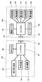
図1は、像振れ補正装置を搭載した、レンズ交換式オートフォーカス(AF)一眼レフカメラシステム(レンズシステムを含む)等の構成を示すブロック図である。
図1に示すように、カメラ本体200に備わるマイクロコンピュータで構成されるカメラCPU201は、カメラ本体200内の後述する種々の装置回路205,206,207,208,209等の動作を制御する。
一方、カメラ本体200には、後述する交換レンズ本体300が着脱可能である。
カメラ本体200に対する交換レンズ本体300の装着時には、レンズ接点302とカメラ接点202が接続されて、交換レンズ本体300とレンズCPU301との間で種々の情報の送受信を行うことが可能になる。
First, the configuration of a camera system including an interchangeable lens and a camera on which a shake correction apparatus according to an embodiment of the present invention is mounted will be described.
FIG. 1 is a block diagram illustrating a configuration of an interchangeable lens autofocus (AF) single-lens reflex camera system (including a lens system) equipped with an image blur correction device.
As shown in FIG. 1, a
On the other hand, an
When the
カメラ本体200の電源スイッチ203は、外部より操作可能であり、カメラCPU201を立ち上げてシステム内の各アクチュエータやセンサ等への電源供給及びシステムの動作を可能な状態とするためのスイッチである。
カメラ本体200のレリーズスイッチ204は、外部より操作可能な2段ストローク式のレリーズスイッチであり、各ストロークスイッチONの信号はカメラCPU201に入力される。
即ち、レリーズスイッチ204の第1ストロークスイッチ(第1のトリガ手段)がONの状態においては、撮影準備段階に移行するための命令(第1のトリガ信号:SW1信号)が出力される。
レリーズスイッチ204の第2ストロークスイッチ(第2のトリガ手段)がONの状態においては、撮影段階に移行するための命令(第2のトリガ信号:SW2信号)が出力される。
なお、レリーズスイッチ204の第2ストロークスイッチがONするストロークは、第1ストロークスイッチがONするストロークよりもさらに深いストロークである。
The
A
That is, when the first stroke switch (first trigger means) of the
When the second stroke switch (second trigger means) of the
Note that the stroke at which the second stroke switch of the
より具体的には、レリーズスイッチ204は、外部よりの操作で、その第1ストロークスイッチがON(トリガ信号:SW1信号発生)した場合は、カメラCPU201の管理の下、次の動作が実行されて撮影準備段階に入る。
即ちカメラCPU201の管理の下、測光装置205による露光量の決定や、測距装置208による被写体の測距演算結果に基づく後述の合焦装置の合焦動作及び合焦判定等が行われる。
一方、レリーズスイッチ204は、外部よりの操作で、その第2ストロークスイッチがON(トリガ信号:SW2信号発生)した場合は、カメラCPU201から次の種々の命令が出力されて撮影段階に入る。
More specifically, when the first stroke switch of the
That is, under the control of the
On the other hand, when the second stroke switch of the
即ちカメラCPU201からの命令のうち一つの命令は、交換レンズ本体300内のレンズCPU301に対する絞り装置307の駆動命令である。
レンズCPU301は、上記命令の受信で絞り装置307を駆動するとともに、カメラCPU201に対し露光装置206の露光開始命令を送信し、露光装置206に実際の露光動作を行わせる。
また、レンズCPU301は、カメラCPU201を介して露光終了信号を受信すると、カメラCPU201に対して記憶装置207への記録開始命令を送信し、記憶装置207に撮影画像の記憶処理を行わせる。
That is, one of the commands from the
The
When the
一方、カメラCPU201は、第1のトリガ信号(SW1信号発生)認識から第2のトリガ信号(SW2信号発生)認識までの間の第1の時間内の振れ情報に基づき後述する振れ補正レンズの振れ補正駆動範囲の中心位置を制御する。
しかし第1、第2のトリガ信号の出力で、後述する振れ補正レンズの振れ補正駆動範囲の中心位置を制御することの具体的な実行はレンズCPU301若しくは振れ補正装置305が実行する方が処理速度の観点からは好ましい。
ただし、振れ補正に際しては、振れ補正レンズが後述する弾性部材に重力により保持された状態での振れ補正レンズの光軸から撮影光学系の光軸の範囲に、前記中心位置を制御するという態様をも含む。
なお、表示装置209は、絞り値やシャッタスピードなどの各種撮影条件や、撮影枚数、電池残量、各種モードを、カメラCPU201の指令により表示を行う装置であり、例えば液晶表示装置である。
On the other hand, the
However, a specific execution of controlling the center position of a shake correction driving range of a shake correction lens, which will be described later, by the output of the first and second trigger signals is performed by the
However, in shake correction, the center position is controlled from the optical axis of the shake correction lens to the optical axis of the photographing optical system in a state where the shake correction lens is held by gravity on an elastic member described later. Including.
The
交換レンズ本体300の外部より操作可能な像振れ補正作動切替スイッチ(以下ISスイッチと記す)303は、後述する像振れ補正動作(以下IS動作と記す)を行わせるか否かの選択(ONでIS動作を選択)用のスイッチである。
交換レンズ本体300の振れ補正装置305は、以下の4つの構成要素に大別される。第1は、振れ補正レンズとそれを保持するレンズ保持部材とからなる振れ補正光学系である。
第2は、振れ補正光学系を駆動するための駆動手段であり、第3は、移動した振れ補正光学系の位置を検出するための位置検出手段である。
第4は、カメラの縦振れおよび横振れの加速度あるいは速度を検出して、振れ補正の対象となる振動状態を検出する振動検出手段である。
An image blur correction operation changeover switch (hereinafter referred to as IS switch) 303 that can be operated from the outside of the
The
The second is drive means for driving the shake correction optical system, and the third is position detection means for detecting the position of the moved shake correction optical system.
The fourth is vibration detection means for detecting the vibration state to be subjected to shake correction by detecting the acceleration or speed of the vertical shake and the horizontal shake of the camera.
交換レンズ本体300の合焦装置306は、次の要素を備えて構成される。即ち第1に、合焦レンズ及びそのレンズ保持部材を備え、第2に、合焦レンズを目標位置まで駆動するための合焦レンズ駆動手段を備える。
また、第3に、合焦レンズ駆動手段による駆動力を合焦レンズの移動力として伝達する伝達機構を備える。
第4には、カメラCPU201から送信された合焦レンズの移動量の情報に基づいてレンズCPU301によって制御される合焦レンズ駆動手段に駆動指令を送る合焦レンズ駆動回路を備える。
The focusing
Third, a transmission mechanism that transmits the driving force of the focusing lens driving unit as the moving force of the focusing lens is provided.
Fourth, a focusing lens driving circuit is provided that sends a driving command to focusing lens driving means controlled by the
交換レンズ本体300の絞り装置307は、次の要素を備えて構成される。即ち第1に、開口面積を設定する絞り機構を備え、第2に、絞り機構を駆動するための絞り機構駆動手段を備える。
また、第3に、カメラCPU201から送信された絞り動作命令に従い、レンズCPU301によって制御される絞り機構駆動手段に駆動指令を送る絞り駆動回路を備える。
なお、レンズCPU301、振れ補正装置305により、後述する振れ検出手段からの振れ情報に基づいて後述するレンズ保持部材の位置を制御する制御回路が構成される。
The
Third, an aperture drive circuit is provided that sends a drive command to the aperture mechanism drive means controlled by the
The
図2は、本発明の実施例1の振れ補正装置を分解して説明する分解斜視図であり、図3は、この振れ補正装置の組み立て状態における光軸方向から視た正面図である。
一方、図4は、この振れ補正装置の組み立て状態における光軸直交方向から視た側面図を含む駆動制御系を説明する説明図であり、以下、図2〜図4を用いて実施例1に係る振れ補正装置を説明する。
まず、レンズ支持枠(レンズ保持部材)1の内周には、図3及び図4に示す貼り合せレンズ(振れ補正光学系:以下、振れ補正レンズと記す)L1が嵌合され、カシメによって固定されている(図3参照)。
FIG. 2 is an exploded perspective view illustrating the shake correction apparatus according to the first embodiment of the present invention in an exploded manner. FIG. 3 is a front view of the shake correction apparatus viewed from the optical axis direction in the assembled state.
On the other hand, FIG. 4 is an explanatory view for explaining a drive control system including a side view viewed from the direction orthogonal to the optical axis in the assembled state of the shake correcting device. Hereinafter, the first embodiment will be described with reference to FIGS. Such a shake correction apparatus will be described.
First, a bonded lens (shake correction optical system: hereinafter referred to as a shake correction lens) L1 shown in FIGS. 3 and 4 is fitted to the inner periphery of the lens support frame (lens holding member) 1 and fixed by caulking. (See FIG. 3).
レンズ支持枠1は、ベース部材(装置本体)2に対して光軸直交面上にて2次元方向(光軸直交方向)に移動可能となっている(図3参照)。
ベース部材2の周方向3箇所における同一光軸直交面上には、図2に示すように、摺動カム2aが設けられている。レンズ支持枠1に形成された3箇所の穴1aには、摺動カム2aを介して金属製の摺動ピン5が圧入されている。
これにより、レンズ支持枠1はベース部材2に対して摺動ピン5と摺勤カム2aとを介して結合し、光軸方向に概ね位置規制された状態で光軸直交面上のすべての方向に移動できるようになっている。
The
As shown in FIG. 2, sliding
As a result, the
摺動ピン5と摺動カム2aとのガタ(つまりはレンズ支持枠1の光軸方向ガタ)については、摺動ピン5の太さを調節することで補正可能である。
また、摺動カム2aは、図2に示すように、ベース部材2のうち外径が一段小さくなっている3箇所の凹部2bの内側に形成されている。
この凹部2bに他の部材等を配置し、この振れ補正装置305が搭載されるレンズ鏡筒やカメラ等における振れ補正装置305の前後の部材を繋ぐことができる。
ベース部材2の外周3箇所には、光学機器内に本振れ補正装置305を支持させるための支持穴2cが設けられている。
この支持穴2cに他の部材、例えば図4に示すコロ10を挿入し、ビス11で締め付け固定することでよって、本振れ補正装置305を光学機器内に支持することができる。
The play between the slide pin 5 and the
Further, as shown in FIG. 2, the sliding
Another member or the like can be disposed in the
Support holes 2c are provided at three locations on the outer periphery of the
By inserting another member, for example, the roller 10 shown in FIG. 4 into the
なお、先に説明したように、摺動ピン5の太さを変えることでレンズ支持枠1の光軸方向ガタを補正した場合、レンズ支持枠1が光軸に対して倒れてしまうおそれがある。
しかし、上記3つのコロ10のうち1つ又は2つを偏心コロにしておけば、偏心コロを回転させるだけで振れ補正装置全体を光学機器の光軸に対して傾けることができる。
このため、レンズ支持枠1の光軸に対する倒れも合わせて補正して実際上の障害を低減し、さらには偏心コロの最適な適用でレンズ支持枠1を光軸に対し障害なく補正することも十分に可能である。
As described above, when the play in the optical axis direction of the
However, if one or two of the three rollers 10 are eccentric rollers, the entire shake correction device can be tilted with respect to the optical axis of the optical device simply by rotating the eccentric rollers.
For this reason, the tilt of the
第1マグネット4p,4yは、図2に示すように、第1ヨーク3にそれぞれ磁気結合により固定されている。第2マグネット7p,7yは、第2ヨーク8にそれぞれ磁気結合されている。
第1マグネット4p,4yは、第1ヨーク3に設けられた突起3aにより位置規制されており、第2マグネット7p,7yは、第2ヨーク8に同様に設けられた突起(図示せず)により位置規制されている。
また、図2に示すように、各マグネット4p,4y,7p,7yは、それぞれ光軸に近い側と遠い側とで着磁方向が異なっており、各マグネット4p,4y,7p,7yの中心付近は非着磁領域になっている。
これは、各マグネット4p,4y,7p,7yに対して光軸方向において対向配置されるコイル6p,6yの巻線の位置と各マグネット4p,4y,7p,7yの着磁領域とを合わせて駆動力を効率よく発生させるためである。
As shown in FIG. 2, the first magnets 4p and 4y are fixed to the first yoke 3 by magnetic coupling. The second magnets 7p and 7y are magnetically coupled to the
The positions of the first magnets 4p and 4y are regulated by a projection 3a provided on the first yoke 3, and the second magnets 7p and 7y are provided by projections (not shown) similarly provided on the
As shown in FIG. 2, the magnets 4p, 4y, 7p, and 7y have different magnetization directions on the side closer to the optical axis and on the side farther from the optical axis, and the centers of the magnets 4p, 4y, 7p, and 7y are different. The vicinity is a non-magnetized region.
This is because the positions of the windings of the coils 6p, 6y arranged opposite to the magnets 4p, 4y, 7p, 7y in the optical axis direction and the magnetized regions of the magnets 4p, 4y, 7p, 7y are combined. This is because the driving force is generated efficiently.
各マグネット4p,4y,7p,7yの着磁方向は、図5に矢印にて示している。詳しくは後述する。
第1ヨーク3は、図2に示すように、第1ヨーク3に形成された2箇所の穴3bにベース部材2に設けられた2箇所の突起2dを挿通させることによってベース部材2に対する位置が決められる。
また、第1ヨーク3は、3箇所の穴3cとベース部材2に形成された3箇所の穴2eに不図示のビスを通して締め付けることでベース部材2に対し固定される。
なお、第1ヨーク3は、製作工程においては、レンズ支持枠1に摺動ピン5を圧入する前にベース部材2に固定される。
The magnetization directions of the magnets 4p, 4y, 7p, and 7y are indicated by arrows in FIG. Details will be described later.
As shown in FIG. 2, the first yoke 3 is positioned with respect to the
Further, the first yoke 3 is fixed to the
In the manufacturing process, the first yoke 3 is fixed to the
第2ヨーク8は、図2に示すように、第2ヨーク8に形成された穴8bと凹部8cにベース部材2に設けられた2箇所の突起2fを挿通させることでベース部材2に対する位置が決められる。
また、第2ヨーク8は、3箇所の穴8dとベース部材2に形成された3箇所の穴2gに不図示のビスを通して締め付けることでベース部材2に対し固定される。
As shown in FIG. 2, the
Further, the
コイル6p,6yは、図2に示すように、導電部材を巻き付けた巻線部6aと、このコイル6p,6yをレンズ支持枠1に固定するために樹脂で形成された支持部6bとを有して構成されている。
コイル6p,6yは、レンズ支持枠1に設けられた腕部1bの上に支持部6bを当接させ、支持部6bに形成された不図示の穴にレンズ支持枠1の突起1cを挿通させることでレンズ支持枠1に対する位置が決められる。
また、コイル6p,6yは、支持部6bをレンズ支持枠1に接着することでレンズ支持枠1に固定される。
As shown in FIG. 2, the coils 6p and 6y have a winding part 6a around which a conductive member is wound, and a support part 6b formed of a resin for fixing the coils 6p and 6y to the
The coils 6p and 6y abut the support portion 6b on the arm portion 1b provided on the
The coils 6p and 6y are fixed to the
実施例1では、図2、図4に示すように、第1ヨーク3,第1マグネット4,第2マグネット7及び第2ヨーク8からなるループ上の閉磁路内に、コイル6p,6yが位置する。
そのため、コイル6p,6yの巻線部6aに通電することで、コイル6p,6y、さらにはレンズ支持枠1、及び振れ補正レンズL1が光軸直交方向のうち、ピッチ方向(P)及びヨー方向(Y)に駆動される。
これは、光学機器に搭載した振れ検出手段(例えば、加速度センサ及び積分回路により構成される:図示せず)が光学機器の振れをピッチ成分とヨー成分に分けて検出していることに対応するものである。
なお、ピッチ方向及びヨー方向は、それぞれ、垂直方向及び水平方向を意味する。
In the first embodiment, as shown in FIGS. 2 and 4, the coils 6 p and 6 y are positioned in the closed magnetic path on the loop including the first yoke 3, the first magnet 4, the second magnet 7, and the
Therefore, by energizing the winding portion 6a of the coils 6p and 6y, the coils 6p and 6y, and further the
This corresponds to the fact that a shake detection means (for example, composed of an acceleration sensor and an integration circuit: not shown) mounted on the optical device detects the shake of the optical device separately for the pitch component and the yaw component. Is.
Note that the pitch direction and the yaw direction mean a vertical direction and a horizontal direction, respectively.
上述の振れ検出手段は、例えば第1のトリガ信号出力から第1の時間の間の第1の時間内の実際上の例えばピッチ方向及びヨー方向の振れ量に基づく振れ情報を生成する。
上記第1の時間の間という概念には、例えば第1のトリガ信号出力から第2のトリガ信号出力までの間という態様が実際上には含まれる。
一方、振れ検出手段が生成する振れ情報は、例えばカメラCPU201、若しくはレンズCPU301及び振れ補正装置305に出力されて、振れ補正レンズL1の振れ補正駆動範囲の中心位置を制御するパラメータとなる。
ただし、振れ補正に際しては、第1に振れ補正レンズL1が後述する弾性部材(圧縮コイルバネ)に重力により保持された状態での振れ補正レンズの光軸から撮影光学系の光軸の範囲に、前記中心位置を制御するという態様を含む。
The shake detection unit described above generates shake information based on, for example, the shake amounts in the pitch direction and the yaw direction in the first time between the first trigger signal output and the first time.
The concept of during the first time actually includes, for example, a mode from the first trigger signal output to the second trigger signal output.
On the other hand, the shake information generated by the shake detection unit is output to, for example, the
However, in shake correction, first, the shake correction lens L1 is in the range from the optical axis of the shake correction lens in a state in which it is held by an elastic member (compression coil spring), which will be described later, to the optical axis of the photographing optical system. The mode of controlling the center position is included.
あるいは第2に前記中心位置の制御には、振れ補正レンズL1が弾性部材に重力により保持された状態での振れ補正レンズL1の光軸から撮影光学系の光軸の範囲に前記中心位置を制御するという態様がある。
若しくは第3に前記中心位置の制御には、振れ検出手段からの第1の振れ出力が第1の出力以下のときは、振れ補正レンズL1が弾性部材に重力により保持された状態を中心に前記中心位置を制御するという態様がある。
この他、第4に振れ検出手段からの第2の振れ出力(振れ量)が第1の振れ出力(振れ量)より大きいとき、振れ補正レンズL1が弾性部材に重力で保持された状態より撮影光学系の光軸寄りに持ち上げた位置を中心に前記中心位置を制御するという態様がある。
Alternatively, secondly, the center position is controlled from the optical axis of the shake correction lens L1 in a state where the shake correction lens L1 is held by gravity to the optical axis range of the photographing optical system. There is a mode of doing.
Alternatively, thirdly, in the control of the center position, when the first shake output from the shake detection unit is equal to or lower than the first output, the shake correction lens L1 is mainly held in the state where the elastic member is held by gravity. There is a mode in which the center position is controlled.
In addition, when the second shake output (shake amount) from the shake detection means is larger than the first shake output (shake amount), the image is taken from the state in which the shake correction lens L1 is held by gravity on the elastic member. There is a mode in which the center position is controlled around a position lifted near the optical axis of the optical system.
一方、レンズ支持枠(レンズ保持部材)1を光軸に対して直交方向に駆動する駆動源は、第1ヨーク3,各マグネット4p,4y,7p,7y,第2ヨーク8,コイル6p,6yにより構成されている。
この駆動源は、振れ補正を行う際は、上述の振れ情報に基づいて振れ補正レンズL1の振れ補正駆動範囲の中心位置を制御すべく、一例としてはレンズCPU301若しくは振れ補正装置305からの制御により駆動する。
また、コイル6p,6yには、不図示の可撓性を有する回路基板から通電が行なわれる。この回路基板(駆動源の一部)上には、本装置の制御に必要な各種電子部品が実装されている。
On the other hand, the drive source for driving the lens support frame (lens holding member) 1 in the direction orthogonal to the optical axis is the first yoke 3, the magnets 4p, 4y, 7p, 7y, the
This drive source, when performing shake correction, controls the center position of the shake correction drive range of the shake correction lens L1 based on the shake information described above, for example, by control from the
The coils 6p and 6y are energized from a flexible circuit board (not shown). Various electronic components necessary for control of the apparatus are mounted on the circuit board (a part of the drive source).
この回路基板は、第2ヨーク8の前側またはベース部材2の後側に固定されており、この回路基板からは他の回路基板との接続のための接続部が延びている。
この接続部の受け部として、図2、図3に示すように、ベース部材2に延出部2hが形成されており、接続部は両面テープ等によって延出部2hに固定される。
なお、この回路基板の動作内容については、一例としてはレンズCPU301若しくは振れ補正装置305からの制御命令に基づくという態様がある。即ち振れ補正を行うという動作内容を含む。
しかし、この回路基板に対し、第1のトリガ信号出力から第2のトリガ信号出力までの間の第1の時間内の振れ情報に基づいて、振れ補正レンズL1の振れ補正駆動範囲の中心位置を制御する機能を直接的に構成してもよい。
あるいは、より詳しくはその回路基板に対し、上記第1から第4までのうち何れか一つ若しくは全部の前記中心位置の制御の態様を直接的に構成してもよい。
The circuit board is fixed to the front side of the
As shown in FIG. 2 and FIG. 3, an
The operation content of the circuit board is based on a control command from the
However, the center position of the shake correction driving range of the shake correction lens L1 is determined for the circuit board based on the shake information within the first time from the first trigger signal output to the second trigger signal output. The function to be controlled may be configured directly.
Alternatively, more specifically, one or all of the first to fourth aspects of the control of the central position may be directly configured on the circuit board.
回路基板(制御回路)の一例としては、図4に示すように、制御回路44p,44yを例示することができる。
制御回路44pは、振れ情報等を検出する検出回路15p、振れ補正の制御量等を演算する演算回路16p、不要信号除去等のフィルタ17p、及びその制御量に応じて上述の駆動源を駆動する駆動回路18pを備える。
制御回路44yは、同じく、振れ情報等を検出する検出回路15y、振れ補正の制御量等を演算する演算回路16y、不要信号除去等のフィルタ17y、及びその制御量に応じて上述の駆動源を駆動する駆動回路18yを備える。
なお、検出回路15p、15y、演算回路16p、16y、駆動回路18p、18yは、いずれも振れ補正に係る情報以外の駆動制御に係る情報を処理することも可能である。例えば、絞り制御、焦点制御等の処理がある。
As an example of the circuit board (control circuit),
The control circuit 44p drives a
Similarly, the
Note that the
レンズ支持枠1とベース部材2との間におけるレンズ支持枠1をピッチ方向にて挟む2箇所には、図2〜図4に示すように、弾性部材としての圧縮コイルバネ(弾性部材)9pa,9pbが配置されている。
また、レンズ支持枠1とベース部材2との間におけるレンズ支持枠1をヨー方向にて挟む2箇所には、図2〜図4に示すように、弾性部材としての圧縮コイルバネ(弾性部材)9ya,9ybが配置されている。
これら圧縮コイルバネ(弾性部材)9pa,9pb,9ya,9ybの光軸側の端面はレンズ支持枠1に凹形状部分の底面として形成された平面部1dに当接する。
平面部1dには突起1eが形成されており、この突起1eが各コイルバネの内側に入り込むことによって、コイルバネの平面部1dからの外れが防止される。
As shown in FIGS. 2 to 4, compression coil springs (elastic members) 9 pa and 9 pb as elastic members are provided at two positions sandwiching the
Further, as shown in FIGS. 2 to 4, compression coil springs (elastic members) 9ya as elastic members are provided at two places between the
The end surfaces on the optical axis side of these compression coil springs (elastic members) 9pa, 9pb, 9ya, 9yb are in contact with a
A
また、圧縮コイルバネ9pa,9pb,9ya,9ybの光軸とは反対側の端面は、図2、図3に示すように、ベース部材2に凹形状部分の底面として形成された平面部2iに当接する。
平面部2iには突起2jが形成されており、この突起2jが各コイルバネの内側に入り込むことによって、コイルバネの平面部2iからの外れが防止される。
そして、図3及び図4に示す組み立て状態においては、各圧縮コイルバネ9pa,9pb,9ya,9ybは圧縮状態となっており、これによりレンズ支持枠1を浮遊支持している。
Further, the end surfaces of the compression coil springs 9pa, 9pb, 9ya, 9yb opposite to the optical axis are in contact with the
A
In the assembled state shown in FIGS. 3 and 4, the compression coil springs 9pa, 9pb, 9ya, 9yb are in a compressed state, thereby supporting the
一方、実施例1の振れ補正装置305には、振れ補正レンズL1の位置を検出するための位置検出手段が設けられている(不図示)。
その位置検出手段の構成には、例えば特開平11−212133号公報に記載されているような位置検出用ターゲット部材とフォトリフレクタ等による構成を用いるという態様がある。
若しくは、その位置検出手段の構成には、例えば特開2005−227329号公報に記載されているようなLED等の発光素子とPSD等の受光素子による構成を用いるという態様がある。
On the other hand, the
As a configuration of the position detecting means, there is an aspect in which a configuration including a position detecting target member and a photo reflector as described in JP-A-11-212133 is used.
Alternatively, the configuration of the position detecting means includes a configuration using a light emitting element such as an LED and a light receiving element such as a PSD as described in JP-A-2005-227329, for example.
コイル6p,6yに入力される電圧(電力)は、振れ補正のための駆動目標値に対応して定まり、駆動目標値は前述した振れ検出手段からの検出出力(振れ情報)と位置検出手段からの検出出力に基づいて設定される。
ここで、圧縮コイルバネ9pa,9pb,9ya,9ybは線形特性を有し、コイル6p,6yへの入力目標値(電圧)に対する発生推力の関係も線形特性を有する。
このため、圧縮コイルバネ9pa,9pb,9ya,9ybの弾性定数(変位に対する弾性力)とコイル6p,6yの推力定数(入力電圧に対する推力)を予め認識しておくことが好ましい。
その弾性定数(変位に対する弾性力)と推力定数(入力電圧に対する推力)に応じて、コイル6p,6yへの入力電圧を調節することで振れ補正レンズL1に所望の変位量を与えることができる。
このため、振れ補正レンズL1の位置を検出するための位置検出手段を廃止することも可能である。
The voltage (power) input to the coils 6p and 6y is determined in accordance with the drive target value for shake correction, and the drive target value is obtained from the detection output (shake information) from the shake detection means and the position detection means. Is set based on the detected output.
Here, the compression coil springs 9pa, 9pb, 9ya, 9yb have a linear characteristic, and the relationship of the generated thrust to the input target value (voltage) to the coils 6p, 6y also has a linear characteristic.
For this reason, it is preferable to recognize in advance the elastic constants (elastic force against displacement) of the compression coil springs 9pa, 9pb, 9ya, 9yb and the thrust constants (thrust against the input voltage) of the coils 6p, 6y.
By adjusting the input voltage to the coils 6p and 6y according to the elastic constant (elastic force against displacement) and the thrust constant (thrust against input voltage), a desired amount of displacement can be given to the shake correction lens L1.
For this reason, it is possible to eliminate the position detection means for detecting the position of the shake correction lens L1.
以上の構成により、実施例1では、従来の振れ補正装置と比較して、一つには振れ補正レンズL1を所定の初期位置にロック保持するためのロック機構を不要とすることが可能である。
また、実施例1では、振れ補正レンズL1の光軸に対する傾きを防止するためのローリング対策機構に関連する部品を不要とすることも可能となり、きわめてシンプルな構成で振れ補正の十分な機能を実現することができる。
With the above configuration, the first embodiment can eliminate the need for a lock mechanism for holding the shake correction lens L1 in a predetermined initial position in comparison with the conventional shake correction device. .
Further, in the first embodiment, it is possible to eliminate the parts related to the rolling countermeasure mechanism for preventing the tilt of the shake correction lens L1 with respect to the optical axis, thereby realizing a sufficient function of shake correction with a very simple configuration. can do.
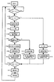
以上の構成よりなる振れ補正装置を搭載したレンズ本体300をカメラ本体200に装着した状態での撮影動作順序の一例を、図5に示すフローチャートを用いて説明する。
まずカメラ本体200の電源がONされた(S101)後、撮影準備段階となるSW1がONであるか否かを判別する(S102)。
ここでON状態である場合は、振れ補正に関係するISスイッチ303がONであるか否かを判別する(S103)。ON状態である場合は、振動ジャイロ等のセンサにより振れ量の検出を開始(振動検出開始)する(S104)。
An example of a shooting operation sequence in a state where the lens
First, after the power source of the
If it is ON, it is determined whether or not the
次いでAF及び測光動作を行った(S105)後、振れ検出手段により第1の時間内の振れ量を検出し(S106)、振れ量より算出される振れ補正中心位置が所定範囲を越えるか否かを判別する(S107)。
振れ補正中心位置が所定範囲を越える場合は、振れ補正範囲の中心位置を算出し(S108)、振れ補正レンズL1の位置検出を開始し(S109)、算出された中心位置に振れ補正範囲を移動させ、振れ補正の駆動を開始する(S110)。
Next, after performing AF and photometry (S105), the shake detection means detects the shake amount within the first time (S106), and whether or not the shake correction center position calculated from the shake amount exceeds a predetermined range. Is discriminated (S107).
When the shake correction center position exceeds the predetermined range, the center position of the shake correction range is calculated (S108), the position detection of the shake correction lens L1 is started (S109), and the shake correction range is moved to the calculated center position. To start shake correction (S110).
ここでS106〜S110の処理をさらに詳しく説明する。振動ジャイロ等のセンサにより検出された振れ量(実際にはセンサの出力値若しくはその出力値に基づいて算出された振れ量を表す値)を抽出する。
ただしその際は第1ストロークスイッチがON(トリガ信号:SW1信号発生)された直後から振れ量の抽出を開始し、一定の時間内の振れ量を抽出する(S106)。
一定時間内とは、一例として第2ストロークスイッチがON(トリガ信号:SW2信号発生)されるまでの時間がある。
そして振れ量の中で最も大きい振れを補正するための補正範囲の中心位置と、カメラ本体200内の記憶装置207に記憶された所定範囲とを比較し、その中心位置が所定範囲を越えるか否かを判別する(S107)。
その中心位置が所定範囲を越えた場合は、振れ補正範囲の中心位置の移動量を算出する処理に移行する(S108)。
Here, the processing of S106 to S110 will be described in more detail. A shake amount detected by a sensor such as a vibration gyro (actually, an output value of the sensor or a value representing a shake amount calculated based on the output value) is extracted.
However, in that case, extraction of the shake amount is started immediately after the first stroke switch is turned ON (trigger signal: SW1 signal is generated), and the shake amount within a certain time is extracted (S106).
The term “within a certain time” includes, for example, a time until the second stroke switch is turned ON (trigger signal: SW2 signal is generated).
Then, the center position of the correction range for correcting the largest shake in the shake amount is compared with the predetermined range stored in the
When the center position exceeds the predetermined range, the process proceeds to processing for calculating the movement amount of the center position of the shake correction range (S108).
次に、振れ補正範囲の中心位置の移動量の算出処理の詳細を図6及び図7を用いてさらに詳細に説明する。図6及び図7は、撮影光学系の光軸方向から見た振れ補正駆動領域を概念的に示す概念図である。
図6及び図7の横軸はヨー方向(図中Y)、縦軸はピッチ方向(図中P)を示す。図6及び図7の振れ補正可能な領域20は、振れ補正レンズL1の光軸が移動できる範囲を示す。これは例えば機械的な移動規制範囲である。
また、実際の振れ補正時の駆動源は、図6及び図7の振れ補正範囲(振れ補正レンズL1の光軸が振れ補正時に移動する範囲)21,22,23を一例として、振れ補正可能な領域よりも若干狭い範囲を定めて駆動する。
これは例えば電気的な移動規制範囲であり、図6及び図7中のA,B,Cはそれぞれ振れ補正範囲21,22,23の中心位置を示す。なお、符号24については後述する。
Next, details of the calculation processing of the movement amount of the center position of the shake correction range will be described in more detail with reference to FIGS. 6 and 7 are conceptual diagrams conceptually showing a shake correction drive region viewed from the optical axis direction of the photographing optical system.
6 and 7, the horizontal axis indicates the yaw direction (Y in the figure), and the vertical axis indicates the pitch direction (P in the figure). 6 and 7 shows a range in which the optical axis of the shake correction lens L1 can move. This is, for example, a mechanical movement restriction range.
Further, as an example of the drive source at the time of shake correction, shake correction can be performed with the shake correction range (range in which the optical axis of the shake correction lens L1 moves during shake correction) 21, 22, and 23 shown in FIGS. 6 and 7 as an example. It is driven by determining a range slightly narrower than the area.
This is, for example, an electric movement restriction range, and A, B, and C in FIGS. 6 and 7 indicate the center positions of the shake correction ranges 21, 22, and 23, respectively.
さて図6の例においては、中心位置Aは光軸と略一致した位置にあり、振れ補正可能な領域20よりも内側(狭い範囲)に振れ補正範囲21がある。
この状態では、振れ補正範囲の全域に渡って振れ補正レンズL1の光軸を移動しても、振れ補正可能な領域20を越えることがなく、良好に振れ補正できる。
しかしこの状態では振れ補正レンズL1を重力に逆らって光軸中心位置に保持する電力を供給し続ける必要があるため、消費電力が増大してしまう。
ただし、実施例1の振れ補正装置305の構成では、振れ補正レンズL1の光軸が振れ補正レンズL1の自重で、撮影光学系の光軸に対して重力方向に若干変位した位置で浮遊支持されている。
したがってその位置を振れ補正範囲の中心位置とすれば、振れ補正レンズL1を重力に逆らって光軸中心位置に保持する電力を供給し続ける必要がなく、消費電力の削減には有利である。
In the example of FIG. 6, the center position A is substantially coincident with the optical axis, and there is a
In this state, even if the optical axis of the shake correction lens L1 is moved over the entire shake correction range, the shake correction can be satisfactorily performed without exceeding the
However, in this state, it is necessary to keep supplying the power for holding the shake correction lens L1 at the center position of the optical axis against gravity, so that the power consumption increases.
However, in the configuration of the
Therefore, if the position is set as the center position of the shake correction range, it is not necessary to continue to supply power for holding the shake correction lens L1 at the center position of the optical axis against gravity, which is advantageous in reducing power consumption.
しかし、自重浮遊している分、重力方向への補正範囲は狭くなり、例えばその浮遊支持された時の中心位置がBの位置である場合、その時の振れ補正範囲は振れ補正可能な領域をLだけ越えてしまう。
このため、大きな振れを補正しようとした時には、補正できずに補正残りが生じてしまうが、これは撮影画像を劣化させる要因となり得る。
そこで、SW1がONされた直後から振れ量の抽出を開始し、一定の時間内の振れ量を抽出し、その中で最も大きい振れを補正した時の振れ補正範囲の中心位置を算出する。
また、第1の振れ出力である振れ補正量が所定値以下のときは、振れ補正レンズL1が弾性部材に重力により保持された状態を中心に前記中心位置を制御する。
ただし、その位置がカメラ内に記憶された所定範囲を越えていれば、振れ補正範囲の中心位置が所定範囲内に入るように、振れ補正レンズL1を光軸寄りに持ち上げる処理をする。
However, the correction range in the direction of gravity is narrowed due to the floating of its own weight. For example, when the center position when the suspension is supported is the position B, the shake correction range at that time is an area where the shake correction is possible. Just over.
For this reason, when a large shake is to be corrected, correction cannot be performed and an uncorrected image remains. This may be a factor that degrades the captured image.
Therefore, the extraction of the shake amount is started immediately after the SW1 is turned on, the shake amount within a certain time is extracted, and the center position of the shake correction range when the largest shake is corrected is calculated.
When the shake correction amount, which is the first shake output, is equal to or less than a predetermined value, the center position is controlled around the state where the shake correction lens L1 is held by the elastic member by gravity.
However, if the position exceeds the predetermined range stored in the camera, a process of lifting the shake correction lens L1 closer to the optical axis is performed so that the center position of the shake correction range falls within the predetermined range.
より具体的には、振れ補正は、上述したように、上記第1の態様、即ち振れ補正レンズL1が弾性部材(圧縮コイルバネ)に重力により保持された状態での振れ補正レンズL1の光軸から撮影光学系の光軸の範囲に前記中心位置を制御するという態様がある。
若しくは上記第2の態様、即ち前記中心位置の制御には、振れ補正レンズL1が弾性部材に重力により保持された状態での振れ補正レンズL1の光軸から撮影光学系の光軸の範囲に前記中心位置を制御するという態様がある。
若しくは上記第3の態様、即ち前記中心位置の制御には、振れ検出手段からの第1の振れ出力が第1の出力以下のときは、振れ補正レンズL1が弾性部材に重力により保持された状態を中心に前記中心位置を制御するという態様がある。
この他、上記第4の態様、即ち第2の振れ出力(振れ量)が第1の振れ出力(振れ量)より大きいときは、振れ補正レンズL1が弾性部材に重力で保持された状態より撮影光学系の光軸寄りに持ち上げた位置を中心に前記中心位置を制御するという態様である。
More specifically, as described above, shake correction is performed from the optical axis of the shake correction lens L1 in the first mode, that is, in a state where the shake correction lens L1 is held by the elastic member (compression coil spring) by gravity. There is an aspect in which the center position is controlled within the range of the optical axis of the photographing optical system.
Or the second aspect, the control of the immediate Chi before Symbol center position, stabilization lens L1 in the range from the optical axis of the optical axis of the imaging optical system of the blur correction lens L1 in a state of being held by gravity in the elastic member There is a mode in which the center position is controlled.
Alternatively, in the third mode, that is, the control of the center position, when the first shake output from the shake detection unit is equal to or lower than the first output, the shake correction lens L1 is held by the elastic member by gravity. There is a mode in which the center position is controlled around the center.
In addition, when the fourth mode, that is, when the second shake output (shake amount) is larger than the first shake output (shake amount), shooting is performed from the state in which the shake correction lens L1 is held by gravity on the elastic member. In this aspect, the center position is controlled around a position lifted near the optical axis of the optical system.
ところで、最も大きい振れを補正した時の振れ補正範囲の中心位置を算出する際には、大きな振れを補正できる限界の振れ補正範囲の中心位置を算出して、できるだけ光軸よりに持ち上げる移動量を減らせば、より省電力化できる。
カメラ内に記憶された所定範囲とは、図6及び図7に示す所定の範囲24の範囲内であり、中心位置がこの範囲内にあれば、振れ補正範囲が振れ補正可能な領域を越えることがない。
図7は中心位置BからCへ移動した(持ち上げた)時の振れ補正範囲を示している。中心位置Cは所定範囲24の範囲内にあり、振れ補正範囲が振れ補正可能な領域内にある。
このため、大きな振れが生じても補正することが可能となり、持ち上げる中心位置は、所定範囲24の範囲内でできるだけ境界付近に設定すれば、光軸位置まで持ち上げるよりも省電力化できる。
By the way, when calculating the center position of the shake correction range when the largest shake is corrected, the center position of the limit shake correction range that can correct the large shake is calculated, and the amount of movement lifted from the optical axis as much as possible is calculated. If it is reduced, power can be saved more.
The predetermined range stored in the camera is within the range of the
FIG. 7 shows a shake correction range when moving from the center position B to C (lifted). The center position C is within the range of the
For this reason, even if a large shake occurs, correction can be performed, and if the center position to be lifted is set as close to the boundary as possible within the range of the
なお、上記では、SW1がONされた直後から抽出を開始して、一定の時間内の振れ量を抽出し、その中で最も大きい振れを補正した時の振れ補正範囲の中心位置を算出する構成とした。
ただし振れ量の抽出時間内にSW2がONされた場合は、それまでの最大値を採用するか、若しくは第1の時間内に抽出された振れ量の平均値を採用してもよい。
また、振れ量を抽出する第1の時間は、SW1がONされてからSW2がONされるまでの時間であってもよい。こうすることで、多くの振れ情報が得られ、より最適な振れ補正範囲の中心位置を設定できる。
In the above, the extraction is started immediately after the SW1 is turned on, the amount of shake within a certain time is extracted, and the center position of the shake correction range when the largest shake is corrected is calculated. It was.
However, when SW2 is turned on within the shake amount extraction time, the maximum value up to that point may be employed, or the average value of the shake amounts extracted within the first time may be employed.
The first time for extracting the shake amount may be a time from when SW1 is turned on to when SW2 is turned on. By doing so, a lot of shake information can be obtained, and a more optimal shake correction range center position can be set.
またSW1がONされた後、若干の待ち時間を経過した後より振れ量の抽出を行うようにしてもよい。
こうすることで、撮影直前と比較してまだ安定していないSW1ON直後の振れを抽出することがないので、より最適な振れ補正範囲の中心位置を設定できる。
これらのように、SW1ONの後の振れ状態を適切に判断できるが、振れ補正範囲の中心位置を算出する方法は、上述の方法に限定されるものではない。
Alternatively, the shake amount may be extracted after a slight waiting time has elapsed after SW1 is turned on.
In this way, since the shake immediately after SW1ON that is not yet stable compared to immediately before shooting is not extracted, a more optimal center position of the shake correction range can be set.
As described above, the shake state after SW1 ON can be appropriately determined, but the method of calculating the center position of the shake correction range is not limited to the above-described method.
一方、図5に示すS107で振れ補正量が所定値を越えていない場合は、振れ補正レンズL1の位置検出を開始する(S114)。
振れ補正レンズL1の光軸が自重で撮影光学系の光軸に対して重力方向に若干変位した位置(コイルバネで浮遊支持された自然状態の位置)を振れ補正範囲の中心位置として振れ補正駆動を開始する(S115)。
振れ補正時の駆動電力には、大きく分けて2つある。可動部材を重力に逆らって、光軸中心位置に保持する電力と、その位置から振れ補正をするためのシフト駆動を行う電力である。
元々バネによって浮遊支持されていることを利用し、振れ補正レンズL1が自重で、光軸に対して重力方向に若干変位した位置(自然状態の位置)をシフト動作による振れ補正の駆動中心とすることで消費電力を削減できる。
このため、振れ補正駆動の省電力化が可能であり、かつ光軸から自然状態の位置に近づくほど消費電力が削減できるため、振れ補正レンズL1を自然状態から持ち上げる量を最小限に留めることで、より省電力化を実現できる。
On the other hand, when the shake correction amount does not exceed the predetermined value in S107 shown in FIG. 5, the position detection of the shake correction lens L1 is started (S114).
The shake correction drive is performed with the position where the optical axis of the shake correction lens L1 is slightly displaced in the gravity direction with respect to the optical axis of the photographing optical system (the position in the natural state floating and supported by the coil spring) as the center position of the shake correction range. Start (S115).
There are roughly two types of driving power for shake correction. These are electric power for holding the movable member at the center position of the optical axis against gravity, and electric power for performing shift driving for correcting shake from that position.
Utilizing the fact that the vibration correction lens L1 is originally supported in a floating manner by a spring, the position (natural position) where the shake correction lens L1 is slightly displaced in the gravity direction with respect to the optical axis is used as a drive center for shake correction by the shift operation. This can reduce power consumption.
For this reason, it is possible to save power in shake correction driving, and power consumption can be reduced as the position closer to the natural state from the optical axis. Therefore, it is possible to minimize the amount by which the shake correction lens L1 is lifted from the natural state. , More power saving can be realized.
次に、SW2がON状態であるか否かを判別する(S111)。ON状態である場合(OFF状態の場合はS102に移行)は、露光動作が行われ(S112)、かつ画像が記憶され(S113)、一連の撮影が終了する。
ところで、S103のステップにおいて、ISスイッチ303がOFFだった場合は、S105と同様のAF、測光動作を行い(S116)、S109と同様の位置検出を開始する(S117)。
そして振れ補正レンズL1が自重で、光軸に対して重力方向に若干変位した位置(自然状態の位置)に保持するような駆動(中心保持駆動)を開始する(S118)。
次いでSW2がON状態であるか否かを判別し(S111)し、ON状態である場合は、上記S112以降のステップに移行する(ただしOFF状態の場合はS102のステップへ移行)。
Next, it is determined whether or not SW2 is in an ON state (S111). If it is ON (if it is OFF, the process proceeds to S102), an exposure operation is performed (S112), an image is stored (S113), and a series of photographing is finished.
By the way, when the
Then, a drive (center holding drive) is started so that the shake correction lens L1 is held by its own weight at a position (natural position) slightly displaced in the gravitational direction with respect to the optical axis (S118).
Next, it is determined whether or not SW2 is in an ON state (S111). If the SW2 is in an ON state, the process proceeds to the steps after S112 (in the case of the OFF state, the process proceeds to S102).
以上説明したように、SW1がONされた後の振動状態に基づいて振れ補正範囲の中心位置を制御するため、撮影準備段階から撮影段階の間に予期せぬ大きな振れが生じた場合でも振れ補正を良好に行うことができる。
即ちSW1がONされた後の振動状態に基づいて振れ補正範囲の中心位置を制御するため、大きな振れを補正する時でも充分な振れ補正ストロークが得られ、良好な振れ補正性能と撮影画像を取得できる。
また、通常は自然状態の位置を振れ補正の中心位置とし、大きな振れを検出した場合には最小限の電力で振れ補正範囲を確保することができ、この観点から省電力化を図ることが可能である。
以上、本発明の好ましい実施例について説明したが、本発明はこれらの実施例に限定されることはなく、その要旨の範囲内で種々の変形及び変更が可能である。
As described above, since the center position of the shake correction range is controlled based on the vibration state after the SW1 is turned on, the shake correction is performed even when an unexpected large shake occurs between the shooting preparation stage and the shooting stage. Can be performed satisfactorily.
That is, since the center position of the shake correction range is controlled based on the vibration state after SW1 is turned on, a sufficient shake correction stroke can be obtained even when correcting a large shake, and a good shake correction performance and a photographed image are obtained. it can.
Normally, the position of the natural state is the center position for shake correction, and when a large shake is detected, the shake correction range can be secured with a minimum amount of power. From this viewpoint, it is possible to save power. It is.
As mentioned above, although the preferable Example of this invention was described, this invention is not limited to these Examples, A various deformation | transformation and change are possible within the range of the summary.
次に、本発明の実施例2を説明する。
第1実施例では、SW1ONの直後から一定の時間、振れ量を抽出する構成としていたが、SW1ONの状態の時間が比較的長かった場合は、SW1ON直後の振れの情報では古く、撮影時の振動状態と異なる可能性がある。
そこで実施例2では、SW2がONされた後に、直前の振れ状態を抽出する構成とした。実施例2の詳しくは図8のフローチャートを用いて説明する。
Next, a second embodiment of the present invention will be described.
In the first embodiment, the shake amount is extracted for a certain period of time immediately after the SW1 ON. However, if the SW1 ON state time is relatively long, the shake information immediately after the SW1 ON is old and the vibration at the time of shooting is long. It may be different from the state.
Therefore, in the second embodiment, the configuration is such that the previous shake state is extracted after SW2 is turned on. Details of the second embodiment will be described with reference to the flowchart of FIG.
まずカメラ本体200の電源がONされた(S201)後、撮影準備段階となるSW1がONであるか否かを判別する(S202)。
ON状態である場合は、ISスイッチ303がONであるか否かを判別する(S203)。ISスイッチ303がON状態である場合、振動ジャイロ等のセンサにより振れ量の検出(振動検出)を開始する(S204)。
次いでAF及び測光動作を行い(S205)、かつ振れ補正レンズL1の位置検出を行う(S206)。
その後、振れ補正レンズL1の光軸が自重で撮影光学系の光軸に対して重力方向に若干変位した位置(コイルバネによって浮遊支持された自然状態の位置)を振れ補正範囲の中心位置として振れ補正駆動を開始する(S207)。
First, after the power source of the
If it is ON, it is determined whether or not the
Next, AF and photometry are performed (S205), and the position of the shake correction lens L1 is detected (S206).
After that, the position where the optical axis of the shake correction lens L1 is slightly displaced in the gravitational direction with respect to the optical axis of the photographing optical system (the position in the natural state floating and supported by the coil spring) is used as the center position of the shake correction range. Driving is started (S207).
次に、SW2がON状態であるか否かを判別する(S208)。ON状態である(OFF状態の場合はS202のステップに移行)場合は、第1の時間内の振れ量を抽出する(S209)。
次いで振れ量より算出される振れ補正中心位置が所定範囲を越えるかどうか判別する(S210)。振れ補正中心位置が所定範囲を越える場合には、振れ補正範囲の中心位置を算出する(S211)。
次いで算出された中心位置に振れ補正範囲を移動させ、振れ補正(振れ補正駆動)を開始する(S212)。
Next, it is determined whether or not SW2 is in an ON state (S208). If it is in the ON state (if it is in the OFF state, the process proceeds to step S202), the shake amount within the first time is extracted (S209).
Next, it is determined whether or not the shake correction center position calculated from the shake amount exceeds a predetermined range (S210). When the shake correction center position exceeds the predetermined range, the center position of the shake correction range is calculated (S211).
Next, the shake correction range is moved to the calculated center position, and shake correction (shake correction drive) is started (S212).
ここでS209〜S212の処理をさらに詳しく説明する。まず振動ジャイロ等のセンサにより検出された振れ量(実際にはセンサの出力値若しくはその出力値に基づいて算出された振れ量を表す値)を抽出する。
その際にSW2がONされた直後に、一定時間前の振れ量を抽出する。そしてその中で最も大きい振れを補正するための補正範囲の中心位置と、カメラ内に記憶された所定範囲とを比較する。
比較の結果、その中心位置が所定範囲を越えた場合は、振れ補正範囲の中心位置の移動量を算出する処理に移行する。その算出処理は実施例1で図6、図7を用いて説明した処理と同一の処理である。
Here, the processing of S209 to S212 will be described in more detail. First, a shake amount detected by a sensor such as a vibration gyro (actually, an output value of the sensor or a value representing a shake amount calculated based on the output value) is extracted.
At that time, immediately after the SW2 is turned on, the shake amount before a certain time is extracted. Then, the center position of the correction range for correcting the largest shake is compared with the predetermined range stored in the camera.
As a result of the comparison, when the center position exceeds the predetermined range, the process proceeds to processing for calculating the movement amount of the center position of the shake correction range. The calculation process is the same as the process described with reference to FIGS. 6 and 7 in the first embodiment.
なお、上記では、SW2がONされた直後から、一定時間前の振れ量を抽出し、その中で最も大きい振れを補正した時の振れ補正範囲の中心位置を算出する構成とした。
しかしこの構成の他に、抽出した振れ量の中で、所定値を越えた振れ量だけをさらに抽出し、それらの平均値を採用したり、第1の時間内に抽出された振れ量のすべての平均値を採用する等してもよい。
要するにSW2ON直前(露光直前でもよい)の振れ状態を判断でき、振れ補正範囲の中心位置を算出できれば、上述の方法に限定されるものではない。
In the above description, the amount of shake before a predetermined time is extracted immediately after SW2 is turned on, and the center position of the shake correction range when the largest shake is corrected is calculated.
However, in addition to this configuration, only the shake amount exceeding the predetermined value is further extracted from the extracted shake amounts, and the average value thereof is adopted, or all of the shake amounts extracted within the first time are used. You may employ | adopt the average value of.
In short, the present invention is not limited to the above method as long as the shake state immediately before SW2 ON (or immediately before exposure) can be determined and the center position of the shake correction range can be calculated.
さて、図8に示すS210で振れ補正量が所定値以下であば、振れ補正レンズL1の光軸が自重で撮影光学系の光軸に対して重力方向に若干変位した位置(浮遊支持された自然状態の位置)を振れ補正範囲の中心位置とする。
即ち第1の振れ出力である振れ補正量が所定値以下のときは、振れ補正レンズL1が弾性部材に重力により保持された状態を中心に中心位置を制御する。
そして振れ補正レンズL1の光軸が自重で撮影光学系の光軸に対して重力方向に若干変位した位置(浮遊支持された自然状態の位置)を振れ補正範囲の中心位置として振れ補正駆動を開始する(S213)。
次いで露光動作が行われ(S219)、画像が記憶され(S220)、一連の撮影が終了する。
If the shake correction amount is equal to or smaller than the predetermined value in S210 shown in FIG. 8, the position where the optical axis of the shake correction lens L1 is slightly displaced in the gravity direction with respect to the optical axis of the photographing optical system by its own weight (floating supported). The position of the natural state) is set as the center position of the shake correction range.
That is, when the shake correction amount, which is the first shake output, is equal to or less than a predetermined value, the center position is controlled around the state where the shake correction lens L1 is held by the elastic member by gravity.
Then, the shake correction drive is started with the position where the optical axis of the shake correction lens L1 is slightly displaced in the gravitational direction with respect to the optical axis of the photographing optical system (the position in the floating state) in the center of the shake correction range. (S213).
Next, an exposure operation is performed (S219), an image is stored (S220), and a series of photographing is finished.
元々バネによって浮遊支持されていることを利用し、振れ補正レンズL1が自重で、光軸に対して重力方向に若干変位した位置(自然状態の位置)をシフト動作による振れ補正の駆動中心とすることで消費電力が削減できる。
このため、振れ補正駆動の省電力化ができる。また、光軸から自然状態の位置に近づくほど消費電力が削減でき、振れ補正レンズL1を自然状態から持ち上げる量を最小限に留めることで、省電力化することができる。
Utilizing the fact that the vibration correction lens L1 is originally supported in a floating manner by a spring, the position (natural position) where the shake correction lens L1 is slightly displaced in the gravity direction with respect to the optical axis is used as a drive center for shake correction by the shift operation. This can reduce power consumption.
For this reason, it is possible to save power in shake correction driving. Further, the closer to the position of the natural state from the optical axis, the power consumption can be reduced, and the amount of lifting the shake correction lens L1 from the natural state can be kept to a minimum, thereby saving power.
ところで、S203のステップにおいて、ISスイッチ303がOFFだった場合は、S205と同様のAF、測光動作を行い(S214)、S206と同様の位置検出を開始する(S215)。
そして振れ補正レンズL1が自重で、光軸に対して重力方向に若干変位した位置(自然状態の位置)に保持するような駆動を開始(中心保持駆動開始)する(S216)。
次いでSW2がON状態であるか否かを判別し(S217)し、ON状態である場合は、S219のステップに移行する(OFF状態の場合はS202のステップへ移行)。
By the way, when the
Then, the shake correction lens L1 starts driving to hold at a position (natural position) slightly displaced in the gravitational direction with respect to the optical axis by its own weight (starts center holding drive) (S216).
Next, it is determined whether or not SW2 is in the ON state (S217). If it is in the ON state, the process proceeds to step S219 (if it is in the OFF state, the process proceeds to step S202).
以上のように構成すれば、露光時の振れに時間的に近い露光直前の振れ情報に基づいて振れ補正範囲の中心位置を制御するため、大きな振れを補正する時でもより確実に充分な振れ補正ストロークが得ることができる。
また、大きな振れを補正する時でもより確実に充分な振れ補正ストロークが得られるため、良好な振れ補正性能と撮影画像を取得することができる。
また、通常は自然状態の位置を振れ補正の中心位置とし、大きな振れを検出した場合には最小限の電力で振れ補正範囲を確保することで、省電力化も可能となる。
With the above configuration, the center position of the shake correction range is controlled based on the shake information immediately before exposure that is close in time to the shake at the time of exposure, so sufficient shake correction can be performed more reliably even when correcting large shakes. Stroke can be obtained.
In addition, even when correcting a large shake, a sufficient shake correction stroke can be obtained more reliably, so that a good shake correction performance and a captured image can be acquired.
Further, normally, the position of the natural state is set as the center position of shake correction, and when a large shake is detected, the shake correction range is secured with the minimum power, thereby saving power.
以上、本発明の好ましい実施例について説明したが、本発明はこれらの実施例に限定されることはなく、その要旨の範囲内で種々の変形及び変更が可能である。
例えば、カメラが画質変更または消費電力変更モード設定可能であった場合、高画質モード時には、常時振れ補正範囲の中心位置を光軸近傍に配置して振れ補正を行うという態様がある。
また、標準または低画質モード若しくは省電力モード時には、本発明の構成の振れ補正動作を行うようにしてもよい。こうすることによって、使用者の多様な要求に応えることができる。
As mentioned above, although the preferable Example of this invention was described, this invention is not limited to these Examples, A various deformation | transformation and change are possible within the range of the summary.
For example, when the camera can change the image quality change mode or the power consumption change mode, there is a mode in which shake correction is performed by always placing the center position of the shake correction range near the optical axis in the high image quality mode.
Further, the shake correction operation of the configuration of the present invention may be performed in the standard, low image quality mode, or power saving mode. By doing so, it is possible to meet various demands of users.
1 レンズ支持枠 L1 振れ補正レンズ
1a 穴 1c 突起 1d 平面部 1e 突起
2 ベース部材 2a 摺動カム 2b 凹部 2c 支持穴
2d 突起 2e 穴 2f 突起 2g 穴
2i 平面部 2j 突起
3 第1ヨーク 3a 突起 3c 穴
4p,4y 第1マグネット 5 摺動ピン
6a 巻線部 6b 支持部 6p、6y コイル
7p,7y 第2マグネット
8 第2ヨーク 8b 穴 8c 凹部 8d 穴
9pa,9pb,9ya,9yb 圧縮コイルバネ
10 コロ 11 ビス 15p,15y 検出回路
16p、16y 演算回路 17p、17y フィルタ
18p、18y 駆動回路
20 補正可能な領域 21,22,23 振れ補正範囲
A,B,C 中心位置 24 所定位置
44p,44y 制御回路
200 カメラ本体 201 カメラCPU
202 カメラ接点 203 電源スイッチ
204 レリーズスイッチ 205 測光回路
206 露光装置 207 記憶装置
208 測距装置 209 表示装置
300 交換レンズ本体 301 レンズCPU
302 レンズ接点 303 ISスイッチ
305 振れ補正装置 306 合焦装値 307 絞り装置
DESCRIPTION OF
202
302
Claims (10)
ベース部材と、
前記振れ補正レンズを保持するレンズ保持部材と、
前記レンズ保持部材を光軸に対して直交方向に駆動する駆動源と、
前記ベース部材と前記レンズ保持部材とに各々一端が固定される弾性部材と、
振れを検出する振れ検出手段と、
前記振れ検出手段からの振れ情報に基づいて前記レンズ保持部材の位置を制御して振れ補正を行う制御手段と、を有する光学装置であって、
撮影準備段階に移行する第1のトリガ信号が入力されてから撮影段階に移行する第2のトリガ信号が入力されるまでの間の所定の時間内の振れ情報に基づき撮影中に必要と予測される振れ補正駆動範囲の大きさに応じて、前記振れ補正レンズの前記振れ補正駆動範囲の中心位置を前記振れ補正レンズが前記弾性部材に重力により保持された状態での前記振れ補正レンズの光軸から前記撮影光学系の光軸方向に持ち上げる移動量を決定し、前記決定した移動量だけ前記振れ補正レンズが前記弾性部材に重力により保持された状態での前記振れ補正レンズの光軸から前記撮影光学系の光軸方向に持ち上げた位置を前記振れ補正駆動範囲の中心として振れ補正を行うことを特徴とする光学装置。 A taking optical system including a shake correction lens;
A base member;
A holding Surure lens holding member said shake correcting lens,
A drive source for driving the lens holding member in a direction orthogonal to the optical axis;
An elastic member, each end of which is fixed to said lens holding member and said base member,
Shake detection means for detecting shake;
Control means for performing shake correction by controlling the position of the lens holding member based on shake information from the shake detection means,
Required during based-out shooting shake information within a predetermined time until the second trigger signal to transition to the shooting stage from the input first trigger signal to shift the imaging preparation stage is input depending on the size of the expected shake correction drive range, the shake correction driving range the stabilization lens center position of the shake correction lens of the shake correcting lens in a state of being held by gravity in the elastic member A movement amount to be lifted from the optical axis in the optical axis direction of the photographing optical system is determined, and the vibration correction lens is held by the elastic member by gravity by the determined movement amount from the optical axis of the vibration correction lens. An optical apparatus that performs shake correction using a position lifted in the optical axis direction of the photographing optical system as a center of the shake correction drive range .
前記振れ検出手段から出力された振れ量が前記所定の値より大きいときは、前記決定した移動量だけ前記振れ補正レンズが前記弾性部材に重力により保持された状態での前記振れ補正レンズの光軸から前記撮影光学系の光軸方向に持ち上げた位置を中心に振れ補正を行うことを特徴とする請求項2記載の光学装置。 When the amount of shake output from the shake detection means is equal to or less than a predetermined value, the shake correction is centered on the position of the optical axis of the shake correction lens when the shake correction lens is held by the elastic member by gravity. And
Can shake amount output from the shake detecting means and the greater than the predetermined value, the light of the shake correcting lens in a state in which the determined by the amount of movement the shake correction lens is held by gravity in the elastic member The optical apparatus according to claim 2 , wherein shake correction is performed around a position lifted from an axis in an optical axis direction of the photographing optical system .
前記第2のトリガ信号が入力された後は、前記決定した移動量だけ前記振れ補正レンズが前記弾性部材に重力により保持された状態での前記振れ補正レンズの光軸から前記撮影光学系の光軸方向に持ち上げた位置を中心に振れ補正を行うことを特徴とする請求項1乃至請求項3のいずれか1項に記載の光学装置。 Between the time when the first trigger signal is input and the time when the second trigger signal is input, the shake correction lens is held by the elastic member by gravity , and the shake correction lens is held .
After the second trigger signal is input , the light of the photographing optical system from the optical axis of the shake correction lens in a state where the shake correction lens is held by the elastic member by gravity by the determined movement amount. The optical apparatus according to claim 1 , wherein shake correction is performed around a position lifted in the axial direction .
前記交換レンズは、
振れ補正レンズを含む撮影光学系と、
ベース部材と、
前記振れ補正レンズを保持するレンズ保持部材と、
前記レンズ保持部材を光軸に対して直交方向に駆動する駆動源と、
前記ベース部材と前記レンズ保持部材とに各々一端が固定される弾性部材と、
振れを検出する振れ検出手段と、
前記振れ検出手段からの振れ情報に基づいて前記レンズ保持部材の位置を制御して振れ補正を行う制御手段と、を含み、
前記カメラは、
撮影準備段階に移行する第1の操作により第1のトリガ信号を出力し、撮影段階に移行する第2の操作により第2のトリガ信号を出力するトリガ手段を有し、
前記交換レンズは、
前記第1のトリガ信号が出力されてから前記第2のトリガ信号が出力されるまでの間の所定の時間内の振れ情報に基づき撮影中に必要と予測される振れ補正駆動範囲の大きさに応じて、前記振れ補正レンズの前記振れ補正駆動範囲の中心位置を前記振れ補正レンズが前記弾性部材に重力により保持された状態での前記振れ補正レンズの光軸から前記撮影光学系の光軸方向に持ち上げる移動量を決定し、前記決定した移動量だけ前記振れ補正レンズが前記弾性部材に重力により保持された状態での前記振れ補正レンズの光軸から前記撮影光学系の光軸方向に持ち上げた位置を前記振れ補正駆動範囲の中心として振れ補正を行うことを特徴とするカメラシステム。 A camera system including an interchangeable lens and a camera to which the interchangeable lens can be attached and detached,
The interchangeable lens is
A taking optical system including a shake correction lens;
A base member;
A lens holding member that holds the blur correction lens,
A drive source for driving the lens holding member in a direction orthogonal to the optical axis;
An elastic member, each end of which is fixed to said lens holding member and said base member,
Shake detection means for detecting shake;
Control means for performing shake correction by controlling the position of the lens holding member based on shake information from the shake detection means,
The camera
The first trigger signal output by the first operation to shift to the imaging preparation stage, a second trigger means for outputting a second trigger signal by the operation to shift to the shadow stage Ta,
The interchangeable lens is
The size of the expected shake correction driving range needed based-out during the shooting to the shake information within a predetermined time until the second trigger signal is output from the first trigger signal is outputted if the said stabilization lens the shake correction optical from the optical axis of the photographing optical system drive range the stabilization lens center position of the shake correcting lens in a state of being held by gravity in the elastic member A movement amount to be lifted in the axial direction is determined, and the shake correction lens is held by the elastic member by gravity by the determined movement amount from the optical axis of the shake correction lens to the optical axis direction of the photographing optical system. A camera system that performs shake correction using a lifted position as a center of the shake correction drive range .
前記振れ検出手段から出力された振れ量が前記所定の値より大きいときは、前記決定した移動量だけ前記振れ補正レンズが前記弾性部材に重力により保持された状態での前記振れ補正レンズの光軸から前記撮影光学系の光軸方向に持ち上げた位置を中心に振れ補正を行うことを特徴とする請求項7記載のカメラシステム。 When the amount of shake output from the shake detection means is equal to or less than a predetermined value, the shake correction is centered on the position of the optical axis of the shake correction lens when the shake correction lens is held by the elastic member by gravity. And
Can shake amount output from the shake detecting means and the greater than the predetermined value, the light of the shake correcting lens in a state in which the determined by the amount of movement the shake correction lens is held by gravity in the elastic member 8. The camera system according to claim 7 , wherein shake correction is performed around a position lifted from the axis in the optical axis direction of the photographing optical system.
前記第2のトリガ信号が出力された後は、前記決定した移動量だけ前記振れ補正レンズが前記弾性部材に重力により保持された状態での前記振れ補正レンズの光軸から前記撮影光学系の光軸方向に持ち上げた位置を中心に振れ補正を行うことを特徴とする請求項6乃至請求項8のいずれか1項に記載のカメラシステム。 Between the time when the first trigger signal is output and the time when the second trigger signal is output, the shake correction lens is held by the elastic member while being held by gravity , and the shake correction lens is held .
After the second trigger signal is output , the light of the photographing optical system from the optical axis of the shake correction lens in a state where the shake correction lens is held by the elastic member by the determined amount of gravity. the camera system according to any one of claims 6 to 8, characterized in that shake correction is performed mainly in the raised position in the axial direction.
Priority Applications (5)
| Application Number | Priority Date | Filing Date | Title |
|---|---|---|---|
| JP2006213782A JP4886418B2 (en) | 2006-08-04 | 2006-08-04 | Optical device and camera system |
| US11/829,576 US7466910B2 (en) | 2006-08-04 | 2007-07-27 | Optical device and camera system |
| CN2007101431762A CN101118365B (en) | 2006-08-04 | 2007-08-03 | Optical device and camera system |
| AT07113778T ATE513245T1 (en) | 2006-08-04 | 2007-08-03 | OPTICAL DEVICE AND CAMERA SYSTEM |
| EP07113778A EP1884817B1 (en) | 2006-08-04 | 2007-08-03 | Optical device and camera system |
Applications Claiming Priority (1)
| Application Number | Priority Date | Filing Date | Title |
|---|---|---|---|
| JP2006213782A JP4886418B2 (en) | 2006-08-04 | 2006-08-04 | Optical device and camera system |
Publications (3)
| Publication Number | Publication Date |
|---|---|
| JP2008040113A JP2008040113A (en) | 2008-02-21 |
| JP2008040113A5 JP2008040113A5 (en) | 2009-09-17 |
| JP4886418B2 true JP4886418B2 (en) | 2012-02-29 |
Family
ID=38657413
Family Applications (1)
| Application Number | Title | Priority Date | Filing Date |
|---|---|---|---|
| JP2006213782A Expired - Fee Related JP4886418B2 (en) | 2006-08-04 | 2006-08-04 | Optical device and camera system |
Country Status (5)
| Country | Link |
|---|---|
| US (1) | US7466910B2 (en) |
| EP (1) | EP1884817B1 (en) |
| JP (1) | JP4886418B2 (en) |
| CN (1) | CN101118365B (en) |
| AT (1) | ATE513245T1 (en) |
Families Citing this family (23)
| Publication number | Priority date | Publication date | Assignee | Title |
|---|---|---|---|---|
| JP4347288B2 (en) * | 2005-11-07 | 2009-10-21 | キヤノン株式会社 | Imaging device |
| JP5121303B2 (en) * | 2007-05-22 | 2013-01-16 | キヤノン株式会社 | Image blur correction apparatus, imaging apparatus, and optical apparatus |
| US7813629B2 (en) * | 2007-07-23 | 2010-10-12 | Fujifilm Corporation | Photographing apparatus, and control method and computer program product for controlling the same |
| JP5517431B2 (en) * | 2008-09-29 | 2014-06-11 | キヤノン株式会社 | Optical apparatus and imaging apparatus |
| CN101840127B (en) * | 2009-03-21 | 2013-06-05 | 鸿富锦精密工业(深圳)有限公司 | Shockproof camera |
| CN101860166B (en) * | 2009-04-08 | 2013-05-08 | 鸿富锦精密工业(深圳)有限公司 | Actuator and shockproof camera module |
| JP2010288236A (en) * | 2009-06-15 | 2010-12-24 | Sanyo Electric Co Ltd | Vibration correction control circuit and imaging apparatus mounted with the same |
| CN101975651B (en) * | 2010-10-27 | 2011-12-07 | 中国科学院西安光学精密机械研究所 | Vibration test fixture for aerospace camera |
| TWI435110B (en) * | 2012-04-03 | 2014-04-21 | Tdk Taiwan Corp | Suspension mechanism for optical image anti-shake device |
| JP6126683B2 (en) * | 2012-04-16 | 2017-05-10 | ノキア テクノロジーズ オーユー | Optimized image stabilization |
| JP6187121B2 (en) * | 2013-10-09 | 2017-08-30 | 株式会社ニコン | Vibration correction device |
| JP6436347B2 (en) * | 2014-01-06 | 2018-12-12 | パナソニックIpマネジメント株式会社 | Lens barrel |
| CN103905704A (en) * | 2014-04-10 | 2014-07-02 | 惠州友华微电子科技有限公司 | Electronic device, camera and optical image stable driving device |
| JP6482197B2 (en) * | 2014-07-16 | 2019-03-13 | キヤノン株式会社 | Image shake correction apparatus, control method thereof, and imaging apparatus |
| JP6700826B2 (en) * | 2016-02-09 | 2020-05-27 | キヤノン株式会社 | Image blur correction apparatus, control method thereof, program, and storage medium |
| JP2018116516A (en) * | 2017-01-19 | 2018-07-26 | トヨタ自動車株式会社 | Vehicle warning device |
| JP6409922B2 (en) * | 2017-08-03 | 2018-10-24 | 株式会社ニコン | Vibration correction device |
| KR102620533B1 (en) * | 2018-10-12 | 2024-01-03 | 삼성전기주식회사 | Camera module |
| US10764501B2 (en) * | 2018-10-30 | 2020-09-01 | Qualcomm Incorporated | Optical image stabilization techniques |
| US10999507B2 (en) * | 2018-10-30 | 2021-05-04 | Qualcomm Incorporated | Optical image stabilization techniques |
| US11350018B2 (en) | 2019-08-06 | 2022-05-31 | Apple Inc. | Camera with bumper for cushioning lateral movement |
| US11579461B1 (en) * | 2019-09-25 | 2023-02-14 | Apple Inc. | Perimeter sheet spring suspension arrangement for camera |
| CN113301238B (en) * | 2021-07-26 | 2021-10-15 | 深圳市正光影像器材有限公司 | Vehicle-mounted camera convenient for rapid assembly and assembly method |
Family Cites Families (10)
| Publication number | Priority date | Publication date | Assignee | Title |
|---|---|---|---|---|
| US6343188B1 (en) * | 1995-03-02 | 2002-01-29 | Canon Kabushiki Kaisha | Vibration correction apparatus and optical device |
| US5696999A (en) * | 1995-09-12 | 1997-12-09 | Nikon Corporation | Image vibration reduction device |
| JPH0980542A (en) * | 1995-09-12 | 1997-03-28 | Nikon Corp | Image moving device |
| JPH11119280A (en) * | 1997-10-17 | 1999-04-30 | Canon Inc | Position controller and correction optical device |
| JP3869926B2 (en) | 1998-01-29 | 2007-01-17 | キヤノン株式会社 | Optical equipment |
| JP2002196384A (en) * | 2000-12-26 | 2002-07-12 | Canon Inc | Optical device and photographing device |
| JP2004258250A (en) | 2003-02-25 | 2004-09-16 | Kyocera Corp | Shake correcting device and imaging apparatus using the same |
| JP2005181712A (en) | 2003-12-19 | 2005-07-07 | Nikon Corp | Camera shake correction system |
| JP4416530B2 (en) | 2004-02-10 | 2010-02-17 | キヤノン株式会社 | Vibration correction apparatus and optical apparatus |
| JP2007163595A (en) * | 2005-12-09 | 2007-06-28 | Canon Inc | Optical equipment |
-
2006
- 2006-08-04 JP JP2006213782A patent/JP4886418B2/en not_active Expired - Fee Related
-
2007
- 2007-07-27 US US11/829,576 patent/US7466910B2/en not_active Expired - Fee Related
- 2007-08-03 AT AT07113778T patent/ATE513245T1/en not_active IP Right Cessation
- 2007-08-03 CN CN2007101431762A patent/CN101118365B/en not_active Expired - Fee Related
- 2007-08-03 EP EP07113778A patent/EP1884817B1/en not_active Not-in-force
Also Published As
| Publication number | Publication date |
|---|---|
| EP1884817A2 (en) | 2008-02-06 |
| EP1884817A3 (en) | 2009-03-25 |
| CN101118365B (en) | 2012-07-11 |
| ATE513245T1 (en) | 2011-07-15 |
| US7466910B2 (en) | 2008-12-16 |
| JP2008040113A (en) | 2008-02-21 |
| EP1884817B1 (en) | 2011-06-15 |
| US20080031605A1 (en) | 2008-02-07 |
| CN101118365A (en) | 2008-02-06 |
Similar Documents
| Publication | Publication Date | Title |
|---|---|---|
| JP4886418B2 (en) | Optical device and camera system | |
| JP5188138B2 (en) | Optical apparatus having image blur correction device | |
| US20070146883A1 (en) | Optical apparatus | |
| JP5183135B2 (en) | Interchangeable lenses and optical equipment | |
| JP5441679B2 (en) | Imaging device | |
| JP2000235206A (en) | Supporting state detector, camera with image blurring correcting function, interchangeable lens with image blurring correcting function and device for image blurring correction | |
| US20150160469A1 (en) | Shake correction apparatus and control method | |
| US6694096B1 (en) | Image stabilization control device for use in camera system optionally including optical characteristics modifying converter | |
| JPH11271833A (en) | Shake correction device and shake correction camera | |
| JP2005173160A (en) | Image blurring correcting apparatus and optical device | |
| JP5161513B2 (en) | Camera shake correction apparatus and method | |
| JP5241396B2 (en) | Optical member control device and control method, lens barrel, imaging device, and control method | |
| JP2002196384A (en) | Optical device and photographing device | |
| JP2009163089A (en) | Lens barrel and optical device having same | |
| JP2007163596A (en) | Optical equipment | |
| JPH0980570A (en) | Shake correcting camera | |
| JP6187121B2 (en) | Vibration correction device | |
| JP5590904B2 (en) | Optical equipment | |
| JP5168981B2 (en) | Blur correction device and optical device | |
| JP6409922B2 (en) | Vibration correction device | |
| JP2011164238A5 (en) | ||
| JP2009169233A (en) | Lens barrel | |
| KR20100020858A (en) | Apparatus for vibration correction in camera | |
| JP2000330156A (en) | Optical apparatus with image blurring correction function | |
| JP2002268108A (en) | Correcting optical instrument |
Legal Events
| Date | Code | Title | Description |
|---|---|---|---|
| RD01 | Notification of change of attorney |
Free format text: JAPANESE INTERMEDIATE CODE: A7421 Effective date: 20090406 |
|
| A521 | Request for written amendment filed |
Free format text: JAPANESE INTERMEDIATE CODE: A523 Effective date: 20090804 |
|
| A621 | Written request for application examination |
Free format text: JAPANESE INTERMEDIATE CODE: A621 Effective date: 20090804 |
|
| RD04 | Notification of resignation of power of attorney |
Free format text: JAPANESE INTERMEDIATE CODE: A7424 Effective date: 20100201 |
|
| RD01 | Notification of change of attorney |
Free format text: JAPANESE INTERMEDIATE CODE: A7421 Effective date: 20100630 |
|
| A977 | Report on retrieval |
Free format text: JAPANESE INTERMEDIATE CODE: A971007 Effective date: 20110704 |
|
| A131 | Notification of reasons for refusal |
Free format text: JAPANESE INTERMEDIATE CODE: A131 Effective date: 20110712 |
|
| A521 | Request for written amendment filed |
Free format text: JAPANESE INTERMEDIATE CODE: A523 Effective date: 20110912 |
|
| TRDD | Decision of grant or rejection written | ||
| A01 | Written decision to grant a patent or to grant a registration (utility model) |
Free format text: JAPANESE INTERMEDIATE CODE: A01 Effective date: 20111206 |
|
| A01 | Written decision to grant a patent or to grant a registration (utility model) |
Free format text: JAPANESE INTERMEDIATE CODE: A01 |
|
| A61 | First payment of annual fees (during grant procedure) |
Free format text: JAPANESE INTERMEDIATE CODE: A61 Effective date: 20111209 |
|
| FPAY | Renewal fee payment (event date is renewal date of database) |
Free format text: PAYMENT UNTIL: 20141216 Year of fee payment: 3 |
|
| FPAY | Renewal fee payment (event date is renewal date of database) |
Free format text: PAYMENT UNTIL: 20141216 Year of fee payment: 3 |
|
| LAPS | Cancellation because of no payment of annual fees |