JP5241396B2 - Optical member control device and control method, lens barrel, imaging device, and control method - Google Patents
Optical member control device and control method, lens barrel, imaging device, and control method Download PDFInfo
- Publication number
- JP5241396B2 JP5241396B2 JP2008238122A JP2008238122A JP5241396B2 JP 5241396 B2 JP5241396 B2 JP 5241396B2 JP 2008238122 A JP2008238122 A JP 2008238122A JP 2008238122 A JP2008238122 A JP 2008238122A JP 5241396 B2 JP5241396 B2 JP 5241396B2
- Authority
- JP
- Japan
- Prior art keywords
- optical member
- unit
- drive
- state
- focus
- Prior art date
- Legal status (The legal status is an assumption and is not a legal conclusion. Google has not performed a legal analysis and makes no representation as to the accuracy of the status listed.)
- Expired - Fee Related
Links
Images


Description
本発明は、例えばレンズ群等の光学部材を駆動する光学部材制御装置、レンズ鏡筒、撮像装置に関するものである。 The present invention relates to an optical member control device that drives an optical member such as a lens group, a lens barrel, and an imaging device.
スチルカメラ、ビデオカメラに代表される撮像装置において、例えば、被写体の映像信号より画面の鮮鋭度を検出し、それが最大となるようにフォーカスレンズの位置を制御して、ピントを合わせる自動焦点調節(AF)装置が知られている。従来、自動焦点調節を行うフォーカスレンズを駆動する手段としては、DCモータやステッピングモータが一般に使用されてきた。しかし、近年、撮像装置の高機能化、高画素化に伴い、高速、かつ、静音なレンズ駆動、及び、高停止精度のレンズ駆動が要求されている。このため、マグネットやヨークからなる磁気回路中にコイルを配設した、いわゆるボイスコイルモータを用い、レンズ群を光軸方向に駆動する機構が提案されている(特許文献1)。
また、自動焦点調節装置の制御方法として、フォーカスレンズの合焦動作後、そのときのAF評価値を記憶し、AF評価値が所定の割合以上変化した場合は合焦動作を再び行う手法が開示されている(特許文献2)。この手法によれば、フォーカスレンズの合焦動作後にモータ電源を切ることで消費電力を低減することができる。また、AF評価値の変化を監視し評価値変化が所定以上の場合は、再度モータ電源を起動して合焦動作を行うことで、ピントボケを防ぐことができる。
Further, as a control method of the automatic focus adjustment apparatus, a method is disclosed in which after the focusing operation of the focus lens, the AF evaluation value at that time is stored, and when the AF evaluation value changes by a predetermined ratio or more, the focusing operation is performed again. (Patent Document 2). According to this method, power consumption can be reduced by turning off the motor power after the focusing operation of the focus lens. Further, when the change in the AF evaluation value is monitored and the change in the evaluation value is equal to or greater than a predetermined value, the motor power supply is started again to perform the focusing operation, thereby preventing out-of-focus blur.
しかし、特許文献1に開示されているようなボイスコイルモータを用いたフォーカス機構の場合、ボイスコイルモータへの通電を行わないときには、機構上フォーカスレンズの位置が固定されない。したがって、レンズ位置を固定するためボイスコイルモータへ常時通電を行い、レンズ位置を保持する必要があり、消費電力が増加するという問題があった。
However, in the case of a focus mechanism using a voice coil motor as disclosed in
本発明の課題は、光学部材の駆動をボイスコイルモータにより行う場合のように、通電を停止した場合に光学部材の位置が固定されない構成において、光学部材を停止位置に保持しながら消費電力を低減できる光学部材制御装置、レンズ鏡筒、撮像装置を提供することである。 An object of the present invention is to reduce power consumption while holding an optical member at a stop position in a configuration in which the position of the optical member is not fixed when energization is stopped, such as when the optical member is driven by a voice coil motor. An optical member control device, a lens barrel, and an imaging device are provided.
本発明の第1の側面としての光学部材制御装置は、撮影光学系の一部を構成し、前記撮影光学系の光軸に沿って移動することにより焦点状態を変化させる光学部材と、前記光学部材を駆動する駆動部と、焦点調節動作にて合焦状態となる前記光学部材の合焦位置を停止位置として記憶し、前記駆動部を制御して前記光学部材を前記停止位置に移動させる制御を行う駆動制御部と、前記光学部材の位置又は移動に関連する状態の変化を検出する状態検出部と、を備え、前記駆動制御部は、焦点調節動作にて前記光学部材の位置が前記合焦位置であると判定された場合に前記駆動部への通電を停止することにより前記光学部材を前記停止位置にて停止させるとともに、前記状態検出部による検出結果を判定して前記駆動部への通電を再開させる場合には前記光学部材を前記停止位置に保持する保持動作を行い、再び焦点調節動作を行うか否かを判定し、該焦点調節動作を行わない場合には引き続き前記光学部材の保持動作を行うか否かを判定することを特徴とする。
An optical member control device according to a first aspect of the present invention comprises a part of a photographing optical system, an optical member that changes a focal state by moving along an optical axis of the photographing optical system, and the optical a driving unit for driving the member, control for moving stores focus position of the optical member to be in-focus state at the focus adjustment operation as a stop position, the optical member by controlling the drive unit to the stopping position And a state detection unit that detects a change in the state related to the position or movement of the optical member, and the drive control unit is configured to adjust the position of the optical member in the focus adjustment operation. The optical member is stopped at the stop position by stopping energization to the drive unit when it is determined that the position is a focal position, and the detection result by the state detection unit is determined to Place to resume energization The have rows holding operation for holding the optical member to the stop position, determines whether to perform the focusing operation again, performs the holding operation of the optical member continue if not performed focal point adjustment operation to It is characterized by determining whether or not .
本発明の第2の側面としてのレンズ鏡筒は、本発明の第1の側面としての光学部材制御装置を備える。 The lens barrel according to the second aspect of the present invention includes the optical member control device according to the first aspect of the present invention.
本発明の第3の側面としての撮像装置は、本発明の第1の側面としての光学部材制御装置と、前記光学部材を介して得られた像を撮像する撮像部とを備える。
本発明の第4の側面としての制御方法は、前記光学部材の駆動制御において、焦点調節動作で前記光学部材の位置が前記合焦位置であると判定された場合に前記駆動制御部が前記駆動部への通電を停止することにより前記光学部材を前記停止位置にて停止させるとともに、前記状態検出部による検出結果を判定して前記駆動部への通電を再開させる場合には前記光学部材を前記停止位置に保持する保持動作を行うステップと、前記保持動作の後で再び焦点調節動作を行うか否かを判定する判定ステップと、前記判定ステップにて焦点調節動作を行わないことが判定された場合に引き続き前記光学部材の保持動作を行うか否かを判定するステップを有する。
An imaging device as a third aspect of the present invention includes the optical member control device according to the first aspect of the present invention, and an imaging unit that captures an image obtained through the optical member.
In the control method according to the fourth aspect of the present invention, in the drive control of the optical member, the drive control unit drives the drive when the focus adjustment operation determines that the position of the optical member is the focus position. The optical member is stopped at the stop position by stopping the energization of the part, and when the detection result by the state detection unit is determined and the energization to the drive unit is resumed, the optical member is A step of performing a holding operation for holding at a stop position, a determination step for determining whether or not to perform a focus adjustment operation again after the holding operation, and a determination that the focus adjustment operation is not performed in the determination step. In this case, the method includes a step of determining whether or not to hold the optical member.
本発明によれば、光学部材の駆動をボイスコイルモータにより行う場合のように、通電を停止した場合に光学部材の位置が固定されない構成において、光学部材を停止位置に保持しながら消費電力を低減できる。 According to the present invention, in a configuration in which the position of the optical member is not fixed when energization is stopped, such as when the optical member is driven by a voice coil motor, power consumption is reduced while the optical member is held at the stop position. it can.
以下、本発明を実施するための最良の形態について図面等を参照して説明する。
なお、以下に示す各図は、模式的に示した図であり、各部の大きさ、形状は、理解を容易にするために、適宜誇張して示している。
また、以下の説明では、具体的な数値、形状、材料等を示して説明を行うが、これらは、適宜変更することができる。
さらに、以下の説明中で前後等の方向を表す文言は、特に断りがない限り、カメラを正位置としたときを基準とし、被写体側を前としている。
ここで、正位置とは、撮影者が通常の状態でカメラを保持したとき、すなわち、撮影光学系の光軸が水平であり、かつ、撮影画面の長手方向が水平方向となる状態でカメラが保持されたときの位置を指すものとする。
The best mode for carrying out the present invention will be described below with reference to the drawings.
In addition, each figure shown below is the figure shown typically, and in order to make an understanding easy, the magnitude | size and shape of each part are exaggerated suitably.
In the following description, specific numerical values, shapes, materials, and the like are shown and described, but these can be changed as appropriate.
Further, in the following description, unless otherwise specified, the wording indicating the direction such as front-rear is based on the time when the camera is in the normal position and the subject side is the front.
Here, the normal position means that when the photographer holds the camera in a normal state, that is, in a state where the optical axis of the photographing optical system is horizontal and the longitudinal direction of the photographing screen is horizontal. It shall refer to the position when held.
(第1実施形態)
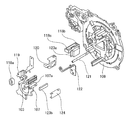
図1は、本発明による光学部材制御装置を用いたカメラの第1実施形態のレンズ鏡筒まわりの分解斜視図である。
第1実施形態のレンズ鏡筒は、2段沈胴型の3群レンズ構成のレンズ鏡筒であり、被写体側(図中の左側)から順に、1群レンズ101、2群レンズ102、及び3群レンズ103がこれらにより構成される撮影光学系の光路中に配置されている。
1群レンズ101は、撮影光学系の一部を構成し、第1鏡筒105により保持されている。1群レンズ101は、光軸方向に沿って移動して位置を変更することにより、倍率変更を行うズームレンズである。
2群レンズ102は、撮影光学系の一部を構成し、光軸に垂直な平面内で他のレンズ群に対して相対的に移動可能となるように第2鏡筒106に保持されている。2群レンズ102は、上述の平面内で移動(シフト)することにより、像ブレを補正するブレ補正動作を行うシフトレンズである。
3群レンズ103は、撮影光学系の一部を構成し、第3鏡筒107により保持され、第3鏡筒107とともに光軸に沿った方向で移動可能となっている。3群レンズ103は、光軸に沿った方向に移動することにより焦点状態を変化させて合焦動作(ピント調整)を行うフォーカスレンズである。
これら3つのレンズ群101、102、103により構成される撮影光学系を透過した被写体像は、ローパスフィルタ110を介して撮像素子104で光電変換されて撮像される。
(First embodiment)
FIG. 1 is an exploded perspective view around a lens barrel of a first embodiment of a camera using an optical member control device according to the present invention.
The lens barrel of the first embodiment is a lens barrel having a two-stage collapsible type three-group lens configuration. The
The
The
The
The subject image that has passed through the photographing optical system constituted by these three
撮像素子104は、撮影光学系により形成された被写体像を光電変換して撮像する撮像部であり、撮像素子地板109により保持されている。
撮像素子地板109には、カバー鏡筒111が固定されている。また、撮像素子地板109には、駆動ギア113を含む減速機構が設けられている。この減速機構は、ズームモータ114が出力する回転駆動力を減速して駆動筒112へ伝える。
カバー鏡筒111及び撮像素子地板109には、駆動筒112が回転可能に保持されている。
駆動筒112は、円筒形状に形成されており、外周部に設けられているギア部112aに駆動ギア113が噛み合い、ズームモータ114の回転により回転駆動される。また、駆動筒112の内周壁には、光軸方向に延びる直線溝112bが周方向に等間隔で3箇所形成されている。
The
A
A
The
駆動筒112の内側には、カバー鏡筒111と撮像素子地板109とに固定された固定筒115が配置されている。
固定筒115には、貫通溝形状の繰り出しカム115aが周方向に等間隔で3箇所形成されている。また、固定筒115の内周壁には、繰り出しテーパカム115bが周方向に等間隔で3箇所形成されている。これら繰り出しカム115aと繰り出しテーパカム115bとは、同じカム軌跡を有している。さらに、固定筒115の内周側には、光軸方向に延びる直進溝115cが周方向に等間隔で3箇所形成されている。
Inside the
In the
固定筒115の内側には、移動カム筒116が配置されている。
移動カム筒116は、円筒形状に形成されており、その外周部には、カムフォロワとなるフォロワピン116aと駆動ピン116bが設けられている。
駆動ピン116bは、フォロワピン116aよりも撮像素子104寄りの位置に設けられている。
フォロワピン116aの先端には、テーパ部が形成されており、このテーパ部は、固定筒115の繰り出しテーパカム115bに係合している。
また、駆動ピン116bは、固定筒115の繰り出しカム115aに係合するとともに、繰り出しカム115aを貫通して直進溝112bにも係合している。
さらに、移動カム筒116の内周には、テーパカム116c及びテーパカム116dがそれぞれ周方向に等間隔で3箇所形成されている。
駆動筒112がズームモータ114の駆動力により光軸回りで回転駆動すると、駆動ピン116bが直進溝112bに係合しているため、移動カム筒116のフォロワピン116aが固定筒115の繰り出しテーパカム115bのリフトにより光軸方向に移動する。
A
The
The
A taper portion is formed at the tip of the
The
Further, on the inner periphery of the
When the
移動カム筒116の内側には、直進筒117が配置されている。
直進筒117は、円筒形状に形成されており、後端側外周部には、突起部117aが周方向に等間隔で3箇所形成されている。この突起部117aは、固定筒115の内周側に形成された直進溝115cに係合している。
このため直進筒117は、固定筒115に対し、光軸方向には移動可能であるが、光軸回りでの回転は阻止される。
また、直進筒117の前端部外周には、突起部117bが周方向に等間隔で3箇所形成されており、この突起部117bは、移動カム筒116の前端に当接している。このため移動カム筒116が光軸方向に移動すると、直進筒117は、移動カム筒116と一体的に光軸方向に移動するが、光軸回りの回転は行わない。さらに、直進筒117には、光軸方向に延びる貫通溝形状の直進溝117cが周方向に等間隔で3箇所形成されている。
A
The
Therefore, the
Further, three
一方、第1鏡筒105の外周部には、フォロワピン105aが周方向に等間隔で3箇所形成されている。このフォロワピン105aは、直進筒117の直進溝117cを貫通して、フォロワピン105aの先端に形成されているテーパ部がテーパカム116cに係合している。このため第1鏡筒105は、移動カム筒116が回転しながら光軸方向に移動するのに連動して、テーパカム116cのリフトにより光軸方向に移動する。
On the other hand, three
また、第2鏡筒106の外周部には、フォロワピン106aが周方向に等間隔で3箇所形成されている。このフォロワピン106aは、直進筒117の直進溝117cを貫通して、フォロワピン106aの先端に形成されているテーパ部がテーパカム116dに係合している。このため第1鏡筒105は、移動カム筒116が回転しながら光軸方向に移動するのに連動して、テーパカム116dのリフトにより光軸方向に移動する。
なお、第2鏡筒106には、2群レンズ102の他にシャッタ・絞りユニット108が設けられている。
Further, three
The
図2は、本発明による光学部材制御装置を用いたカメラを示すブロック図である。
第1実施形態のカメラは、1群レンズ101、2群レンズ102、3群レンズ103からなる撮影光学系を有するレンズ鏡筒により得られる被写体像を、静止画又は動画として撮像する撮像装置である。
ズーム駆動制御部401は、ズームレンズとしての1群レンズ101の光軸に沿った方向の移動を駆動制御する。具体的には、ズーム駆動制御部401は、ズームモータ114への通電を制御することにより、1群レンズ101の駆動を制御する。なお、ズーム駆動制御部401が1群レンズ101の光軸方向の移動を駆動制御することにより、シャッタ・絞りユニット108及び2群レンズ102の光軸に沿った方向の駆動も制御される。
FIG. 2 is a block diagram showing a camera using the optical member control apparatus according to the present invention.
The camera of the first embodiment is an imaging device that captures a subject image obtained by a lens barrel having a photographing optical system including a
The zoom
シャッタ・絞りユニット駆動制御部402は、シャッタ・絞りユニット108を駆動制御する。ここで、シャッタ・絞りユニット108の駆動制御とは、シャッタの開閉、及び、絞り開口径の駆動制御を指す。
シフトレンズ駆動制御部403は、シフトレンズとしての2群レンズ102の光軸に垂直な平面での移動(シフト)を駆動制御する。
フォーカス駆動制御部404は、フォーカスレンズとしての3群レンズ103の光軸に沿った方向の移動を制御する駆動制御部である。
撮像信号処理部405は、撮像素子104から出力された電気信号を映像信号に変換処理する。
映像信号処理部406は、撮像信号処理部405から出力された映像信号を用途に応じて加工する。
表示部407は、映像信号処理部406から出力された信号に基づいて、必要に応じて画像表示を行う。
表示制御部408は、撮像素子104及び表示部407の動作・表示を制御する。
The shutter / aperture unit
The shift lens
The focus
The imaging
The video
The
The
姿勢情報制御部409は、後述の姿勢判定部416から得た情報に基づいて、映像信号処理部406及び表示部407に対して撮影装置の姿勢に応じた設定を行う。
制御部410は、カメラ全体を制御する。
電源部411は、カメラ全体に用途に応じて電源を供給する。
外部入出力端子部412は、外部との間で通信信号及び映像信号を入出力する。
操作部413は、カメラを操作するための各種釦、タッチパネル等の操作入力手段である。この操作部413は、押し込み量に応じて第1スイッチ及び第2スイッチが順にオンするように構成された不図示のシャッタレリーズボタンを有している。シャッタレリーズボタンを約半分押し込んだときに第1スイッチがオンし、シャッタレリーズボタンを最後まで押し込んだときに第2スイッチがオンする構造となっている。
記憶部414は、映像情報など様々なデータを記憶する。
姿勢センサ415は、傾斜センサを用いてカメラの姿勢に応じた信号を姿勢判定部416へ出力する。
姿勢判定部416は、姿勢センサ415から得た信号により、カメラの姿勢がどのような状態にあるのかを判定し、その判定結果を制御部410へ出力する。
The posture
The
The
The external input /
The
The
The
The
次に、本実施形態のカメラの動作について説明する。
操作部413のシャッタレリーズボタンの第1スイッチがオンされると、フォーカス駆動制御部404が3群レンズ103を駆動してピント調整を行うとともに、シャッタ・絞りユニット駆動制御部402がシャッタ・絞り108を駆動して適正な露光量に設定する。さらに、操作部413のシャッタレリーズボタンが押し込まれて第2スイッチがオンされると、撮像素子104に露光された光像から得られた画像データを記憶部414に記憶する。
このとき、撮影者が操作部413を操作することなどにより、ブレ補正機能オンの設定がされていれば、制御部410は、シフトレンズ駆動制御部403にブレ補正動作を指示する。そして、この指示を受けたシフトレンズ駆動制御部403は、ブレ補正機能オフの指示がなされるまでブレ補正動作を行う。
Next, the operation of the camera of this embodiment will be described.
When the first switch of the shutter release button of the
At this time, if the photographer operates the
本実施形態では、操作部413が一定時間操作されなかった場合、制御部410は、省電力のために表示部407の電源を遮断して表示を行わない指示を出す。
また、本実施形態のカメラでは、静止画撮影モードと動画撮影モードとのうちの一方を操作部413より選択可能であり、それぞれのモードにおいて各アクチュエータ制御部の動作条件を変更することができる。
さらに、操作部413に対して1群レンズ101による変倍を行わせる操作があると、制御部410を介して指示を受けたズーム駆動制御部401が1群レンズ101を駆動して、指示されたズーム位置に1群レンズを移動する。
さらにまた、撮像素子104から送られ、撮像信号処理部405,映像信号処理部406によって処理された画像情報に基づいて、フォーカス駆動制御部404が3群レンズ103を駆動してピント調整を行う。
In the present embodiment, when the
In the camera of this embodiment, one of the still image shooting mode and the moving image shooting mode can be selected by the
Further, when there is an operation for causing the
Further, based on image information sent from the
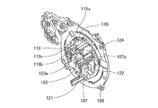
図3は、3群レンズ103の駆動機構と撮像素子地板109とを示す分解斜視図である。
図4は、3群レンズ103の駆動機構と撮像素子地板109とを組み立てた状態を示す斜視図である。
本実施形態の3群レンズ103の駆動機構は、3群レンズ103を駆動する駆動部として、ボイスコイルモータを用いている。
本実施形態のボイスコイルモータは、コイル118a、マグネット118b、ヨーク118cを備えている。
コイル118aは、第3鏡筒107に固定されており、フレキシブル基板119が電気的に接続されている。
マグネット118b、及び、ヨーク118cは、固定部材120を介して撮像素子地板109に固定されている。
FIG. 3 is an exploded perspective view showing the driving mechanism of the
FIG. 4 is a perspective view showing a state in which the driving mechanism of the
The driving mechanism of the
The voice coil motor of this embodiment includes a
The
The
撮像素子地板109には、ガイド軸121が光軸に平行となるように支持部材122により取り付けられている。なお、支持部材122は、撮像素子地板109に対してビス止め固定されている。
第3鏡筒107は、嵌合部107aがガイド軸121に対して移動可能となるように嵌合している。よって、第3鏡筒107は、光軸に沿った方向に滑らかに直進移動可能である。
A
The
フォーカス駆動制御部404に制御されてフレキシブル基板119を介してコイル118aに通電すると、マグネット118b及びヨーク118cで形成される磁気回路の作用により、第3鏡筒107は、ガイド軸121にガイドされて光軸に沿った方向に駆動される。
一方、コイル118aへの通電が行われないときには、第3鏡筒107は、ガイド軸121にガイドされて光軸に沿った方向に自由に移動可能な状態であり、特定の位置に保持されない。
なお、第3鏡筒107の移動可能な範囲は、撮像素子地板109と第3鏡筒107との突き当て面から撮像素子地板109にビス止め固定された支持部材122と第3鏡筒107との突き当て面までである。
When the
On the other hand, when the
The movable range of the
また、本実施形態の3群レンズ103の駆動機構は、その位置又は移動に関連する状態の変化を検出する状態検出部として、3群レンズ103の位置を検出する位置検出部を有している。本実施形態の位置検出部は、センサ123a及びスケール123bを備えている。
スケール123bは、弾性保持部材124により第3鏡筒107に弾性保持されている。このスケール123bには、所定のピッチで溝部が形成されており、センサ123aとともに用いることにより光学式のリニアスケールとして機能する。
また、撮像素子地板109には、スケール123bに対向して、所定の間隔を空けてセンサ123aが固定部材120により取り付けられている。センサ123aには、発光素子と受光素子が実装されており、発光素子から発光される光束がスケール123bの溝部に反射して、その反射光束を受光素子により受光することで出力信号を得る。センサ123aには、例えば、SRセンサ等を用いることができる。
Further, the driving mechanism of the
The
In addition, a
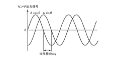
図5は、センサ123aの受光素子から得られる周期波形の出力の例を示す図である。
固定されたセンサ123aに対し、スケール123bを固定した第3鏡筒107が移動すると、センサ123aから図5に示すような90degの位相差を有する正弦波信号が出力される。これらの2相の出力により、スケール123bの移動量と移動方向を判定することができる。ここで、第3鏡筒107の初期位置は、第3鏡筒107と撮像素子地板109との突き当てにより決定される。
なお、センサ123aの出力は3相以上でもよい。また、位相角も90deg以外の角度でもよい。さらに、第3鏡筒107の初期位置は、初期位置検出用のセンサを設けて、このセンサからの出力により決めてもよい。
FIG. 5 is a diagram illustrating an example of an output of a periodic waveform obtained from the light receiving element of the
When the
The output of the
次に、本実施形態のカメラのフォーカス動作について説明する。
図6は、第1実施形態のフォーカス動作を示すフローチャートである。
図7は、第1実施形態のボイスコイルモータの停止及び再起動の変更を示す状態遷移図である。
ステップ(以下、Sとする)1で処理が開始されると、まずS2でウォブリング動作により3群レンズ103を微小駆動させながらAF評価値を演算し、現在合焦しているのか、ボケているのかを判断する。ここで、AF評価値とは、3群レンズ103の移動中に撮像素子104から得られる焦点検出領域の画像についての合焦度の評価値(焦点評価値)であり、例えばコントラストの大きさを表す値を用いることができる。本実施形態では、制御部410がAF評価値を算出する。また、ウォブリング動作とは、3群レンズ103を光軸に沿った方向で微小な範囲で往復駆動を繰り返す動作である。
Next, the focus operation of the camera of this embodiment will be described.
FIG. 6 is a flowchart showing the focus operation of the first embodiment.
FIG. 7 is a state transition diagram showing changes in stop and restart of the voice coil motor of the first embodiment.
When the processing is started in step (hereinafter referred to as S) 1, first, in S2, the AF evaluation value is calculated while slightly driving the
S3では、S2のウォブリング動作の結果により、現在合焦状態にあるかどうか、すなわちAF動作の停止位置である合焦位置に3群レンズ103があるか否かを判別する。
非合焦と判断した場合には、S4へ進み、ウォブリング動作による判定結果の方向へ山登り動作を実行する。
次にS5で合焦点、すなわち、AF評価信号の頂点を越えたかどうかを判定する。AF評価信号の頂点を越えていなければ山登りを続け、越えていればS6、S7で頂点に3群レンズ103を戻す。
しかし、頂点に戻す動作をしている間に、パンニング等により被写体が変化する場合もあるので、S7で頂点に3群レンズ103が辿り着いたならば、今いるところが本当に頂点、即ち合焦点であるのかを判定するため、再びS2へ戻り、再びウォブリング動作を行う。このように、S3で非合焦と判断した場合には、合焦が完了するまでウォブリングを繰り返す。
In S3, based on the result of the wobbling operation in S2, it is determined whether or not the in-focus state is present, that is, whether or not the
If it is determined that the image is out of focus, the process proceeds to S4, and a mountain climbing operation is executed in the direction of the determination result by the wobbling operation.
Next, in S5, it is determined whether or not the focal point, that is, the vertex of the AF evaluation signal has been exceeded. If the vertex of the AF evaluation signal is not exceeded, the mountain climbing is continued, and if it exceeds, the
However, since the subject may change due to panning or the like while returning to the vertex, if the
一方、S3で合焦であると判定した場合は、フォーカス駆動部404がボイスコイルモータのコイル118aへの通電を切り3群レンズ103を停止し、S8からの再起動監視処理ルーチンへ進む。
これは、図7に示すウォブリング状態(801)から合焦完了(805)し、AF終了状態(802)に遷移した状態に相当する。
On the other hand, when it is determined in S3 that the focus is achieved, the
This corresponds to a state in which focusing is completed (805) from the wobbling state (801) shown in FIG. 7 and a transition is made to the AF end state (802).
再起動監視処理ルーチンでは、まず、S8で合焦時のAF評価値レベルを記憶する。
S9では、現在の3群レンズ103の停止位置を後述する保持動作における保持位置として記憶する。
S10では、ボイスコイルモータのコイル118aへの通電による消費電力低減のために、ボイスコイルモータのコイル118aへの通電を停止し、ボイスコイルモータの動作を停止する(図7:モータ停止状態(803))。
ここで、上述したように消費電力低減のためにボイスコイルモータのコイル118aへの通電は停止する。しかし、その後のレンズ位置の移動を検出するため、3群レンズ103の位置検出センサ123aの電源及び、カメラの姿勢変化を検出する姿勢センサ415、及び、姿勢判定部416の電源は切らずに、これらへの通電は継続する。
In the restart monitoring process routine, first, the AF evaluation value level at the time of focusing is stored in S8.
In S9, the current stop position of the
In S10, in order to reduce power consumption by energizing the
Here, energization to the
S11では、表示部407の表示がオンしているか、表示部407の電源が遮断されて表示がオフしているかを判断する。表示がオンしている場合には、S14へ進み、表示がオフしている場合には、S12へ進む。
S12では、3群レンズ103をAF開始位置へ移動した後、ボイスコイルモータのコイル118aへの通電を停止し、ボイスコイルモータの動作を停止する。
S13では、現在の3群レンズ103の停止位置であるAF開始位置を後述する保持動作における保持位置として記憶する。
このように本実施形態では、撮影画像の表示を行う表示部407の表示のオン/オフと連動して、表示がオフである場合には、3群レンズ103を後述の保持動作により予め設定されたAF開始位置に保持させる。これにより、表示が再開されてAF動作を再開するときに素早くAF動作を開始できる。なお、表示部407の表示がオフのときに3群レンズ103を保持する位置は、AF開始位置以外の位置としてもよい。
In S11, it is determined whether the display of the
In S12, after moving the
In S13, the AF start position, which is the current stop position of the
As described above, in the present embodiment, when the display is off in conjunction with the on / off of the display of the
S14では、保持通電判定ルーチンを開始する。保持通電判定ルーチンとは、3群レンズ103の位置を保持するために、ボイスコイルモータへの通電が必要であるか否かを判定するルーチンである。
具体的には、S15で、3群レンズ103の位置を検出するセンサ123aを用いて、フォーカス駆動制御部404によってある周期毎に現在の3群レンズ103の位置と、S9又はS13において記憶しておいたボイスコイルモータ停止直前の3群レンズ103の位置とを比較する。この比較は、現在の3群レンズ103の位置とボイスコイルモータ停止直前の3群レンズ103の位置との差の絶対値を求め、これを予め設定した閾値と比較することにより行う。
ここで、上述の閾値は、被写界深度に応じた値とする。したがって、閾値は、その時点における撮影光学系の焦点距離、絞り値によって変化するように設定されている。これは、AFのピントに影響するフォーカス位置のずれは、被写界深度によって異なるからである。
また、位置の差を求めるために用いる値としては、実際の位置をμm等の寸法を用いてもよいし、センサ123aから得られるデータを直接用いてもよい。
In S14, a holding energization determination routine is started. The holding energization determination routine is a routine for determining whether or not energization of the voice coil motor is necessary to hold the position of the
Specifically, in S15, the
Here, the threshold value is a value corresponding to the depth of field. Therefore, the threshold value is set so as to change depending on the focal length and aperture value of the photographing optical system at that time. This is because the shift of the focus position that affects the AF focus varies depending on the depth of field.
In addition, as a value used for obtaining the difference in position, the actual position may be a dimension such as μm, or data obtained from the
S15において、これら位置の差の絶対値が閾値以内、すなわち、現在の3群レンズ103の位置がボイスコイルモータ停止直前の3群レンズ103の位置から移動した量が予め設定した量以内であれば、保持通電の必要なしと判定し、S16に進む。
S16では、モータ停止状態を維持する。
In S15, if the absolute value of the difference between these positions is within the threshold value, that is, the amount by which the current position of the
In S16, the motor stop state is maintained.
一方、S15において、3群レンズ103の位置変化が閾値以上であると判定した場合、ボイスコイルモータのコイル118aへの保持通電が必要であると判断して(図7:レンズ位置変化あり810)、S17へ進む。
S17では、ボイスコイルモータの再起動を行う(図7:モータ再起動状態804)。
S18では、ボイスコイルモータのコイル118aへの保持通電を開始し、3群レンズ103を保持位置に保持する駆動制御を行う。
On the other hand, if it is determined in S15 that the position change of the
In S17, the voice coil motor is restarted (FIG. 7: motor restart state 804).
In S18, holding energization to the
なお、ボイスコイルモータのコイル118aへのモータへの通電開始は、操作部413のシャッタレリーズボタンの押下タイミングでも行い、レリーズボタン押下直後は、保持動作によるレンズの位置が安定しないため、保持動作による位置が安定するのに必要な所定の時間経過後に露光を開始する。
Note that the energization of the motor to the
その後、S19では、AF評価値による再AF判定(再度AF動作を行う必要があるか否かの判定)を行う再AF判定ルーチンを行う。
この再AF判定ルーチンでは、現在のAF評価値レベルが、合焦時にS8で記憶したレベルに比べ、変動した度合いにより再AF判定を行う。例えば、記憶したレベルに対して所定%以上変化したら、パンニング等による被写体変化があったとして「再度のAF動作が必要」と判断し、所定%未満の変化量ならば被写体の変化はないとして「再度のAF動作は不要」と判断する。
S20では、再AF条件を満たしたか否かを判定し、満たしていればS2に戻り(図7:AF評価値変化検出(812))、再度ウォブリング動作(図7:ウォブリング中(801))に移行する。
一方、S20において再AF条件を満たさなければ、再AFの必要はないので再度保持通電判定ルーチンS14に戻り、引き続き保持通電を行う必要があるかを判定する。ここで、3群レンズ103の移動量が再び所定範囲内に収まっていれば、再度S16においてボイスコイルモータを停止し、保持通電判定ルーチンS14に戻る。
なお、図示しないが、S11で表示部407の表示がオフしていると判断されている場合には、この再AF判定ルーチンはスキップされて、S14を行う。
Thereafter, in S19, a re-AF determination routine for performing re-AF determination (determination of whether or not it is necessary to perform AF operation again) based on the AF evaluation value is performed.
In this re-AF determination routine, the re-AF determination is performed based on the degree of fluctuation of the current AF evaluation value level compared to the level stored in S8 at the time of focusing. For example, if it changes by a predetermined percentage or more with respect to the stored level, it is determined that the subject has changed due to panning or the like, and “re-AF operation is necessary”. It is determined that a second AF operation is unnecessary.
In S20, it is determined whether or not the re-AF condition is satisfied. If it is satisfied, the process returns to S2 (FIG. 7: AF evaluation value change detection (812)), and the wobbling operation is again performed (FIG. 7: during wobbling (801)). Transition.
On the other hand, if the re-AF condition is not satisfied in S20, there is no need for re-AF, so the process returns to the holding energization determination routine S14 again to determine whether it is necessary to continue holding energization. Here, if the movement amount of the
Although not shown, when it is determined in S11 that the display on the
以上説明したように、本実施形態では、3群レンズ103の位置変化があったときにのみ保持動作を行うので、ボイスコイルモータのコイル118aへの保持通電を行う時間を低減できる。よって、消費電力を低減しながら、3群レンズ103の位置を特定の位置に保持することができる。
As described above, in the present embodiment, since the holding operation is performed only when the position of the
(第2実施形態)
第1実施形態では、ボイスコイルモータの停止と再起動との状態変更をモータ停止前に保存した3群レンズ103の位置と現在の3群レンズ103の位置とをセンサ123aを用いて検出した。そして、この3群レンズ103の位置変化が所定値以上かどうかで保持動作を行うか否かの判定を行う例を示した。
第2実施形態では、別の判定方法として、姿勢判定部416から得た情報に基づいて、カメラ姿勢の変化により、ボイスコイルモータのコイル118aへの保持通電を停止、及び、再開する方法を示す。
すなわち、第1実施形態の3群レンズ103の駆動機構は、その位置又は移動に関連する状態の変化を検出する状態検出部として、3群レンズ103の位置を検出する位置検出部を用いていた。これに対して、第2実施形態では、姿勢センサ415、及び、姿勢判定部416を状態検出部として用い、これらの検出結果に基づいて保持動作を行うか否かの判定を行う。
第2実施形態は、動作の内容が一部異なる他は、第1実施形態と同様な構成をしている。よって、前述した第1実施形態と同様の機能を果たす部分には、同一の符号を付して、重複する説明を適宜省略する。
(Second Embodiment)
In the first embodiment, the
In the second embodiment, as another determination method, a method of stopping and restarting energization of the
That is, the driving mechanism of the
The second embodiment has the same configuration as the first embodiment except that the contents of the operation are partially different. Therefore, the same reference numerals are given to the portions that perform the same functions as those in the first embodiment described above, and repeated descriptions are omitted as appropriate.
図8は、第2実施形態のフォーカス動作を示すフローチャートである。
第2実施形態の基本的な動作フローは、第1実施形態と重複しているので、ここでは、第1実施形態と異なる部分について説明する。
S1からS8は、第1実施形態と同様である。
S31では、姿勢センサ415、及び、姿勢判定部416を使用してボイスコイルモータ停止直前のカメラ姿勢を保存する。
S32は、第1実施形態のS10と同様である。
S33では、第1実施形態と同様に保持通電判定ルーチンを開始する。保持通電判定ルーチンとは、3群レンズ103の位置を保持するために、ボイスコイルモータへの通電が必要であるか否かを判定するルーチンである。ただし、第2実施形態では、判定の方法が第1実施形態とは異なっている。
具体的には、S34において、ボイスコイルモータの駆動方向(ガイド軸121の長手方向)へ影響するカメラ姿勢(カメラ上向き、下向き方向)の変化があったと判定すると、ボイスコイルモータへの保持通電を開始する。
S35からS39は、第1実施形態のS16からS20と同様である。
FIG. 8 is a flowchart showing the focus operation of the second embodiment.
Since the basic operation flow of the second embodiment is the same as that of the first embodiment, only different parts from the first embodiment will be described here.
S1 to S8 are the same as in the first embodiment.
In S31, the posture of the camera immediately before stopping the voice coil motor is stored using the
S32 is the same as S10 of the first embodiment.
In S33, the holding energization determination routine is started as in the first embodiment. The holding energization determination routine is a routine for determining whether or not energization of the voice coil motor is necessary to hold the position of the
Specifically, when it is determined in S34 that there has been a change in the camera posture (camera upward or downward direction) that affects the driving direction of the voice coil motor (longitudinal direction of the guide shaft 121), the holding energization to the voice coil motor is performed. Start.
S35 to S39 are the same as S16 to S20 of the first embodiment.
以上説明したように、本実施形態では、カメラの姿勢に変化があったときにのみ保持動作を行うので、ボイスコイルモータのコイル118aへの保持通電を行う時間を低減できる。よって、消費電力を低減しながら、3群レンズ103の位置を特定の位置に保持することができる。
As described above, in this embodiment, the holding operation is performed only when the posture of the camera is changed. Therefore, the time for holding and energizing the
(変形形態)
以上説明した実施形態に限定されることなく、種々の変形や変更が可能であって、それらも本発明の範囲内である。
(1)各実施形態において、保持動作を行う対象としてフォーカスレンズである3群レンズ103を例に挙げて説明した。しかし、フォーカスレンズ以外の他のレンズであってもよい。また、屈折作用を与えるレンズの他、他の作用を光に対して及ぼす光学部材であってもよい。例えば、光を反射するミラーであってもよいし、光を遮光するシャッタや絞り等の遮光部材であってもよいし、光を偏向したり、回折したり、一部を透過したりする各種フィルタであってもよい。
(Deformation)
The present invention is not limited to the embodiment described above, and various modifications and changes are possible, and these are also within the scope of the present invention.
(1) In each of the embodiments, the
(2)各実施形態において、フォーカスレンズである3群レンズ103をウォブリング動作させながら合焦位置を求めるいわゆる山登り駆動を行うコントラストAF方式を例に挙げて説明したが、これに限らず、例えば、位相差AF方式等の他のAF方式であってもよい。
(2) In each of the embodiments, the contrast AF method that performs so-called hill-climbing driving for obtaining the in-focus position while performing the wobbling operation of the
(3)第2実施形態では、カメラの姿勢判定に、傾斜センサを使用する例を示した。これに限らず、例えば、3群レンズの制御量(例えば、フォーカス駆動制御部が演算しているカメラ姿勢の重力負荷によって増減する積分制御量)の変化を用いて傾斜を検出して姿勢の変化を検知し、保持動作を行うか否かの判定を行ってもよい。このようにすれば、傾斜センサ等を設置する必要がなくなり、部品配置のスペースが不要となり、より小型な装置とできる。 (3) In 2nd Embodiment, the example which uses an inclination sensor for the attitude | position determination of the camera was shown. Not limited to this, for example, the change in posture by detecting the tilt using the change in the control amount of the third lens group (for example, the integral control amount that increases or decreases due to the gravitational load of the camera posture calculated by the focus drive control unit) May be detected to determine whether to perform the holding operation. In this way, it is not necessary to install an inclination sensor or the like, and no space for component placement is required, and a smaller device can be obtained.
(4)各実施形態において、レンズ鏡筒がカメラ本体部分に一体的に取り付けられているカメラを例に挙げて説明したが、これに限らず、例えば、カメラ本体に対して着脱自在な交換レンズの形態のレンズ鏡筒であってもよい。 (4) In each embodiment, the camera in which the lens barrel is integrally attached to the camera body has been described as an example. However, the present invention is not limited to this. For example, an interchangeable lens that is detachable from the camera body. It may be a lens barrel of the form.
なお、第1実施形態、第2実施形態及び変形形態は、適宜組み合わせて用いることもできるが、詳細な説明は省略する。また、本発明は以上説明した各実施形態によって限定されることはない。 Note that the first embodiment, the second embodiment, and the modified embodiments can be used in appropriate combination, but detailed description thereof is omitted. Further, the present invention is not limited by the embodiments described above.
101 1群レンズ
102 2群レンズ
103 3群レンズ
104 撮像素子
105 第1鏡筒
105a フォロワピン
106 第2鏡筒
106a フォロワピン
107 第3鏡筒
108 シャッタ・絞りユニット
109 撮像素子地板
110 ローパスフィルタ
111 カバー鏡筒
112 駆動筒
112a ギア部
112b 直進溝
113 駆動ギア
114 ズームモータ
115 固定筒
115a 繰り出しカム
115b 繰り出しテーパカム
115c 直進溝
116 移動カム筒
116a フォロワピン
116b 駆動ピン
116c、116d テーパカム
117 直進筒
117a 突起部
117b 突起部
117c 直進溝
118a コイル
118b マグネット
118c ヨーク
119 フレキシブル基板
120 固定部材
121 ガイド軸
122 支持部材
123a センサ
123b スケール
124 弾性保持部材
401 ズーム駆動制御部
402 シャッタ・絞りユニット駆動制御部
403 シフトレンズ駆動制御部
404 フォーカス駆動制御部
405 撮像信号処理部
406 映像信号処理部
407 表示部
408 表示制御部
409 姿勢情報制御部
410 制御部
411 電源部
412 外部入出力端子部
413 操作部
414 記憶部
415 姿勢センサ
416 姿勢判定部
DESCRIPTION OF
Claims (13)
前記光学部材を駆動する駆動部と、
焦点調節動作にて合焦状態となる前記光学部材の合焦位置を停止位置として記憶し、前記駆動部を制御して前記光学部材を前記停止位置に移動させる制御を行う駆動制御部と、
前記光学部材の位置又は移動に関連する状態の変化を検出する状態検出部と、
を備え、
前記駆動制御部は、焦点調節動作にて前記光学部材の位置が前記合焦位置であると判定された場合に前記駆動部への通電を停止することにより前記光学部材を前記停止位置にて停止させるとともに、前記状態検出部による検出結果を判定して前記駆動部への通電を再開させる場合には前記光学部材を前記停止位置に保持する保持動作を行い、再び焦点調節動作を行うか否かを判定し、該焦点調節動作を行わない場合には引き続き前記光学部材の保持動作を行うか否かを判定すること、
を特徴とする光学部材制御装置。 An optical member that constitutes a part of the photographing optical system and changes a focal state by moving along the optical axis of the photographing optical system ;
A drive unit for driving the optical member;
The focus position of the optical member to be in-focus state is stored as the stop position in focusing operation, a drive control unit for performing control by controlling the driving unit moves the optical member to the stop position,
A state detecting unit for detecting a change in a state related to the position or movement of the optical member;
With
The drive control unit stops the optical member at the stop position by stopping energization of the drive unit when it is determined in the focus adjustment operation that the position of the optical member is the in- focus position . together is, whether when to resume the power supply to the drive unit determines the detection result by the state detection unit have rows holding operation for holding the optical member to the stop position, performs a focusing operation again Determining whether to continue the holding operation of the optical member when the focus adjustment operation is not performed,
An optical member control device.
前記駆動制御部は、前記光学部材が停止した前記停止位置と前記位置検出部により検出した前記光学部材の現在の位置との差を、閾値と比較して前記保持動作を行うか否かを判定すること、
を特徴とする請求項1に記載の光学部材制御装置。 The state detection unit includes a position detection unit that detects a position of the optical member,
The drive control unit determines whether to perform the holding operation by comparing a difference between the stop position at which the optical member is stopped and the current position of the optical member detected by the position detection unit with a threshold value. To do,
The optical member control device according to claim 1.
前記駆動制御部は、前記姿勢判定部の判定結果に基づいて、前記保持動作を行うか否かを判定すること、
を特徴とする請求項1又は請求項2に記載の光学部材制御装置。 The state detection unit includes a posture determination unit that determines what state the posture of the optical member control device is in,
The drive control unit determines whether to perform the holding operation based on a determination result of the posture determination unit;
The optical member control device according to claim 1 or 2, wherein
を特徴とする請求項3に記載の光学部材制御装置。 The posture determination unit determines the posture based on an output from the posture sensor or a change in a control amount by the drive control unit;
The optical member control device according to claim 3.
を特徴とする請求項1から請求項4までのいずれか1項に記載の光学部材制御装置。 The drive unit uses a voice coil motor;
The optical member control apparatus according to any one of claims 1 to 4, wherein
前記光学部材を介して得られた像を撮像する撮像部と、
を備える撮像装置。 The optical member control device according to any one of claims 1 to 5 ,
An imaging unit that captures an image obtained through the optical member;
An imaging apparatus comprising:
を特徴とする請求項7に記載の撮像装置。 The drive control unit determines whether to perform the holding operation by comparing a difference between the stop position at which the optical member is stopped and the current position of the optical member detected by the position detection unit with a threshold value. , causing the threshold is changed in accordance with the depth of field,
The imaging apparatus according to claim 7 .
を特徴とする請求項7または請求項8に記載の撮像装置。 The drive control unit performs the holding operation when the imaging unit performs imaging;
The image pickup apparatus according to claim 7 or 8 , wherein:
を特徴とする請求項9に記載の撮像装置。 The imaging unit performs imaging after the holding operation is stabilized after the drive control unit starts the holding operation;
The imaging apparatus according to claim 9 .
前記駆動制御部は、前記表示部が前記撮影画像の表示を行わないときには、予め設定した位置を前記停止位置として前記光学部材を停止させるとともに、前記状態検出部による検出結果を判定して前記駆動部への通電を再開させる場合には前記光学部材を前記停止位置に移動させて前記保持動作を行うこと、
を特徴とする請求項7から請求項10までのいずれか1項に記載の撮像装置。 It has a display unit that displays captured images,
When the display unit does not display the captured image, the drive control unit stops the optical member using the preset position as the stop position, and determines the detection result by the state detection unit to perform the drive Moving the optical member to the stop position to perform the holding operation when resuming energization to the unit ,
The imaging device according to any one of claims 7 to 10, wherein
前記光学部材を駆動する駆動部と、
焦点調節動作にて合焦状態となる前記光学部材の合焦位置を停止位置として記憶し、前記駆動部を制御して前記光学部材を前記停止位置に移動させる制御を行う駆動制御部と、
前記光学部材の位置又は移動に関連する状態の変化を検出する状態検出部と、
を備えた光学部材制御装置にて実行される制御方法であって、
前記光学部材の駆動制御にて、焦点調節動作で前記光学部材の位置が前記合焦位置であると判定された場合に前記駆動制御部が前記駆動部への通電を停止することにより前記光学部材を前記停止位置にて停止させるとともに、前記状態検出部による検出結果を判定して前記駆動部への通電を再開させる場合には前記光学部材を前記停止位置に保持する保持動作を行うステップと、
前記保持動作の後で再び焦点調節動作を行うか否かを判定する判定ステップと、
前記判定ステップにて焦点調節動作を行わないことが判定された場合に引き続き前記光学部材の保持動作を行うか否かを判定するステップを有すること、
を特徴とする光学部材制御装置の制御方法。 An optical member that constitutes a part of the photographing optical system and changes a focal state by moving along the optical axis of the photographing optical system;
A drive unit for driving the optical member ;
A drive control unit that stores a focus position of the optical member that is in a focused state in a focus adjustment operation as a stop position, and controls the drive unit to move the optical member to the stop position;
A state detecting unit for detecting a change in a state related to the position or movement of the optical member;
A control method executed by an optical member control device comprising:
In the drive control of the optical member, when the position of the optical member is determined to be the in-focus position by a focus adjustment operation, the drive control unit stops energization to the drive unit, thereby the optical member Performing a holding operation for holding the optical member at the stop position when the detection result by the state detection unit is determined and the energization to the drive unit is resumed.
A determination step of determining whether to perform the focus adjustment operation again after the holding operation;
A step of determining whether or not to perform the holding operation of the optical member when it is determined that the focus adjustment operation is not performed in the determination step;
A control method for an optical member control device.
前記光学部材を駆動する駆動部と、
焦点調節動作にて合焦状態となる前記光学部材の合焦位置を停止位置として記憶し、前記駆動部を制御して前記光学部材を前記停止位置に移動させる制御を行う駆動制御部と、
前記光学部材の位置又は移動に関連する状態の変化を検出する状態検出部と、
を備えた撮像装置にて実行される制御方法であって、
前記光学部材の駆動制御にて、焦点調節動作で前記光学部材の位置が前記合焦位置であると判定された場合に前記駆動制御部が前記駆動部への通電を停止することにより前記光学部材を前記停止位置にて停止させるとともに、前記状態検出部による検出結果を判定して前記駆動部への通電を再開させる場合には前記光学部材を前記停止位置に保持する保持動作を行うステップと、
前記保持動作の後で再び焦点調節動作を行うか否かを判定する判定ステップと、
前記判定ステップにて焦点調節動作を行わないことが判定された場合に引き続き前記光学部材の保持動作を行うか否かを判定するステップを有すること、
を特徴とする撮像装置の制御方法。
An optical member that constitutes a part of the photographing optical system and changes a focal state by moving along the optical axis of the photographing optical system;
A drive unit for driving the optical member ;
A drive control unit that stores a focus position of the optical member that is in a focused state in a focus adjustment operation as a stop position, and controls the drive unit to move the optical member to the stop position;
A state detecting unit for detecting a change in a state related to the position or movement of the optical member;
A control method executed by an imaging apparatus comprising:
In the drive control of the optical member, when the position of the optical member is determined to be the in-focus position by a focus adjustment operation, the drive control unit stops energization to the drive unit, thereby the optical member Performing a holding operation for holding the optical member at the stop position when the detection result by the state detection unit is determined and the energization to the drive unit is resumed.
A determination step of determining whether to perform the focus adjustment operation again after the holding operation;
A step of determining whether or not to perform the holding operation of the optical member when it is determined that the focus adjustment operation is not performed in the determination step;
A method for controlling an image pickup apparatus.
Priority Applications (1)
| Application Number | Priority Date | Filing Date | Title |
|---|---|---|---|
| JP2008238122A JP5241396B2 (en) | 2008-09-17 | 2008-09-17 | Optical member control device and control method, lens barrel, imaging device, and control method |
Applications Claiming Priority (1)
| Application Number | Priority Date | Filing Date | Title |
|---|---|---|---|
| JP2008238122A JP5241396B2 (en) | 2008-09-17 | 2008-09-17 | Optical member control device and control method, lens barrel, imaging device, and control method |
Publications (3)
| Publication Number | Publication Date |
|---|---|
| JP2010072211A JP2010072211A (en) | 2010-04-02 |
| JP2010072211A5 JP2010072211A5 (en) | 2011-11-04 |
| JP5241396B2 true JP5241396B2 (en) | 2013-07-17 |
Family
ID=42204071
Family Applications (1)
| Application Number | Title | Priority Date | Filing Date |
|---|---|---|---|
| JP2008238122A Expired - Fee Related JP5241396B2 (en) | 2008-09-17 | 2008-09-17 | Optical member control device and control method, lens barrel, imaging device, and control method |
Country Status (1)
| Country | Link |
|---|---|
| JP (1) | JP5241396B2 (en) |
Families Citing this family (3)
| Publication number | Priority date | Publication date | Assignee | Title |
|---|---|---|---|---|
| JP6263941B2 (en) * | 2013-10-08 | 2018-01-24 | 株式会社ニコン | Lens barrel and photographing apparatus |
| JP6604372B2 (en) * | 2017-12-21 | 2019-11-13 | 株式会社ニコン | Lens barrel and photographing device |
| WO2023189463A1 (en) * | 2022-03-30 | 2023-10-05 | ソニーグループ株式会社 | Lens device, photographing device, control method, and photographing system |
Family Cites Families (9)
| Publication number | Priority date | Publication date | Assignee | Title |
|---|---|---|---|---|
| JPH05150152A (en) * | 1991-11-27 | 1993-06-18 | Canon Inc | Image pickup device |
| JP3658020B2 (en) * | 1993-09-29 | 2005-06-08 | キヤノン株式会社 | Imaging device |
| JPH0754971B2 (en) * | 1993-10-08 | 1995-06-07 | 三洋電機株式会社 | Autofocus video camera |
| JP3412984B2 (en) * | 1995-09-04 | 2003-06-03 | キヤノン株式会社 | Lens control device and optical equipment |
| JP4136519B2 (en) * | 2002-07-31 | 2008-08-20 | キヤノン株式会社 | Imaging apparatus and control method thereof |
| JP2005121941A (en) * | 2003-10-17 | 2005-05-12 | Canon Inc | Projector and projector system |
| JP2006146255A (en) * | 2004-10-18 | 2006-06-08 | Mitsubishi Electric Corp | Imaging apparatus and lens drive method |
| JP5059376B2 (en) * | 2005-11-09 | 2012-10-24 | パナソニック株式会社 | Camera device and camera system |
| JP4834610B2 (en) * | 2007-06-04 | 2011-12-14 | キヤノン株式会社 | Imaging apparatus and control method thereof |
-
2008
- 2008-09-17 JP JP2008238122A patent/JP5241396B2/en not_active Expired - Fee Related
Also Published As
| Publication number | Publication date |
|---|---|
| JP2010072211A (en) | 2010-04-02 |
Similar Documents
| Publication | Publication Date | Title |
|---|---|---|
| US8724012B2 (en) | Camera body and camera system using driving method information indicating capability of controlling focus lens | |
| JP5604293B2 (en) | Camera system | |
| US20170192247A1 (en) | Optical control apparatus, optical apparatus, and storage medium for storing optical control program | |
| WO2009139192A1 (en) | Camera system | |
| US9294658B2 (en) | Lens barrel, imaging device and camera | |
| CN107333054B (en) | Image stabilization apparatus, control method thereof, and storage medium | |
| US9432567B2 (en) | Image pickup apparatus and imaging method that perform focus action following zoom action | |
| US9398220B2 (en) | Shake correction apparatus and image pickup apparatus thereof, and optical device mountable on image pickup apparatus | |
| US8988594B2 (en) | Lens barrel, imaging pickup device, and camera | |
| JP5178186B2 (en) | Lens position control device and control method thereof | |
| JP4549083B2 (en) | Optical equipment | |
| JP5241396B2 (en) | Optical member control device and control method, lens barrel, imaging device, and control method | |
| JP2004219581A (en) | Automatic focusing device | |
| JP2013024900A (en) | Lens control device of optical apparatus | |
| US9756259B2 (en) | Shooting apparatus including a diaphragm | |
| JP2019120886A (en) | Image blur correction device and method for controlling the same | |
| JP4363070B2 (en) | Camera system | |
| JP2011043638A (en) | Lens-driving device and image pickup device | |
| JP5803390B2 (en) | Optical equipment | |
| EP1840615B1 (en) | Lens apparatus and imaging apparatus | |
| JP5451058B2 (en) | IMAGING DEVICE, IMAGING DEVICE CONTROL METHOD, IMAGING DEVICE CONTROL PROGRAM | |
| US20230016323A1 (en) | Optical apparatus and camera system | |
| US20230055253A1 (en) | Optical apparatus, image stabilization device, lens barrel, and image pickup apparatus | |
| JP2009098394A (en) | Imaging device | |
| JP7166949B2 (en) | CONTROL DEVICE, AND LENS DEVICE AND IMAGING DEVICE INCLUDING THE SAME |
Legal Events
| Date | Code | Title | Description |
|---|---|---|---|
| A521 | Request for written amendment filed |
Free format text: JAPANESE INTERMEDIATE CODE: A523 Effective date: 20110915 |
|
| A621 | Written request for application examination |
Free format text: JAPANESE INTERMEDIATE CODE: A621 Effective date: 20110915 |
|
| A977 | Report on retrieval |
Free format text: JAPANESE INTERMEDIATE CODE: A971007 Effective date: 20120919 |
|
| A131 | Notification of reasons for refusal |
Free format text: JAPANESE INTERMEDIATE CODE: A131 Effective date: 20120925 |
|
| A521 | Request for written amendment filed |
Free format text: JAPANESE INTERMEDIATE CODE: A523 Effective date: 20121112 |
|
| TRDD | Decision of grant or rejection written | ||
| A01 | Written decision to grant a patent or to grant a registration (utility model) |
Free format text: JAPANESE INTERMEDIATE CODE: A01 Effective date: 20130305 |
|
| A61 | First payment of annual fees (during grant procedure) |
Free format text: JAPANESE INTERMEDIATE CODE: A61 Effective date: 20130402 |
|
| FPAY | Renewal fee payment (event date is renewal date of database) |
Free format text: PAYMENT UNTIL: 20160412 Year of fee payment: 3 |
|
| FPAY | Renewal fee payment (event date is renewal date of database) |
Free format text: PAYMENT UNTIL: 20160412 Year of fee payment: 3 |
|
| LAPS | Cancellation because of no payment of annual fees |