JP4837707B2 - Insert part welding method for fuel tank and fuel tank - Google Patents
Insert part welding method for fuel tank and fuel tank Download PDFInfo
- Publication number
- JP4837707B2 JP4837707B2 JP2008176964A JP2008176964A JP4837707B2 JP 4837707 B2 JP4837707 B2 JP 4837707B2 JP 2008176964 A JP2008176964 A JP 2008176964A JP 2008176964 A JP2008176964 A JP 2008176964A JP 4837707 B2 JP4837707 B2 JP 4837707B2
- Authority
- JP
- Japan
- Prior art keywords
- insert part
- fuel tank
- welding
- insert
- parison
- Prior art date
- Legal status (The legal status is an assumption and is not a legal conclusion. Google has not performed a legal analysis and makes no representation as to the accuracy of the status listed.)
- Expired - Fee Related
Links
Images


Classifications
-
- B—PERFORMING OPERATIONS; TRANSPORTING
- B29—WORKING OF PLASTICS; WORKING OF SUBSTANCES IN A PLASTIC STATE IN GENERAL
- B29C—SHAPING OR JOINING OF PLASTICS; SHAPING OF MATERIAL IN A PLASTIC STATE, NOT OTHERWISE PROVIDED FOR; AFTER-TREATMENT OF THE SHAPED PRODUCTS, e.g. REPAIRING
- B29C49/00—Blow-moulding, i.e. blowing a preform or parison to a desired shape within a mould; Apparatus therefor
- B29C49/20—Blow-moulding, i.e. blowing a preform or parison to a desired shape within a mould; Apparatus therefor of articles having inserts or reinforcements ; Handling of inserts or reinforcements
- B29C2049/2017—Blow-moulding, i.e. blowing a preform or parison to a desired shape within a mould; Apparatus therefor of articles having inserts or reinforcements ; Handling of inserts or reinforcements outside the article
-
- B—PERFORMING OPERATIONS; TRANSPORTING
- B29—WORKING OF PLASTICS; WORKING OF SUBSTANCES IN A PLASTIC STATE IN GENERAL
- B29C—SHAPING OR JOINING OF PLASTICS; SHAPING OF MATERIAL IN A PLASTIC STATE, NOT OTHERWISE PROVIDED FOR; AFTER-TREATMENT OF THE SHAPED PRODUCTS, e.g. REPAIRING
- B29C49/00—Blow-moulding, i.e. blowing a preform or parison to a desired shape within a mould; Apparatus therefor
- B29C49/20—Blow-moulding, i.e. blowing a preform or parison to a desired shape within a mould; Apparatus therefor of articles having inserts or reinforcements ; Handling of inserts or reinforcements
- B29C2049/2021—Inserts characterised by the material or type
- B29C2049/2026—Neck portions
-
- B—PERFORMING OPERATIONS; TRANSPORTING
- B29—WORKING OF PLASTICS; WORKING OF SUBSTANCES IN A PLASTIC STATE IN GENERAL
- B29C—SHAPING OR JOINING OF PLASTICS; SHAPING OF MATERIAL IN A PLASTIC STATE, NOT OTHERWISE PROVIDED FOR; AFTER-TREATMENT OF THE SHAPED PRODUCTS, e.g. REPAIRING
- B29C49/00—Blow-moulding, i.e. blowing a preform or parison to a desired shape within a mould; Apparatus therefor
- B29C49/20—Blow-moulding, i.e. blowing a preform or parison to a desired shape within a mould; Apparatus therefor of articles having inserts or reinforcements ; Handling of inserts or reinforcements
- B29C2049/2095—Means for preparing or treating the inserts, e.g. cutting, deforming, heating, cooling or applying adhesives
-
- B—PERFORMING OPERATIONS; TRANSPORTING
- B29—WORKING OF PLASTICS; WORKING OF SUBSTANCES IN A PLASTIC STATE IN GENERAL
- B29L—INDEXING SCHEME ASSOCIATED WITH SUBCLASS B29C, RELATING TO PARTICULAR ARTICLES
- B29L2031/00—Other particular articles
- B29L2031/712—Containers; Packaging elements or accessories, Packages
- B29L2031/7172—Fuel tanks, jerry cans
Description
本発明は、燃料タンクなどのブロー成形体に各種インサート部品を溶着するインサート部品溶着成形方法とブロー成形体に関する。 The present invention relates to an insert part welding molding method and a blow molded article for welding various insert parts to a blow molded article such as a fuel tank.
従来のインサート部品溶着成形方法としては、インサート部品の溶着部位に鍔状に設けた溶着座の周縁部を傾斜角度で面取りすることにより、その溶着座をブロー成形体(燃料タンク)の成形時に展開中のパリソンに密着させ溶着する方法が知られている(例えば、特許文献1参照)。 Conventional insert part welding molding methods include chamfering the peripheral edge of the weld seat provided in a bowl shape at the welded part of the insert part at an inclined angle, so that the weld seat is deployed when molding the blow molded body (fuel tank). There is known a method of closely contacting and welding the inner parison (for example, see Patent Document 1).
従来のインサート部品溶着成形方法においては、燃料タンクのブロー成形時にインサート部品を金型へセットし、金型閉め時にパリソンをインサート部品の溶着座に密着させ溶着させている。
しかし、図7(a)に示すように、インサート部品100の厚み方向周縁部に立壁101があり、パリソン102と溶着しない箇所103が発生する場合がある。この場合には強度不足を招くおそれがある。
また、インサート部品の厚み方向周縁部の溶着を向上させるため、インサート部品の予熱温度や予熱板温度を夫々高めに温度設定するとインサート部品が溶けて成形不良になってしまう。
In the conventional insert part welding molding method, the insert part is set in the mold when the fuel tank is blow-molded, and the parison is brought into close contact with the insert part welding seat when the mold is closed.
However, as shown to Fig.7 (a), the standing
Moreover, in order to improve the welding of the peripheral part in the thickness direction of the insert part, when the preheating temperature and the preheating plate temperature of the insert part are set higher, the insert part melts and defective molding occurs.
溶着しない箇所103が発生するのを避けるために、図7(b)に示すように、インサート部品100の周縁部でパリソン102の一部をオーバーハング部104を形成させて、インサート部品100を包み込む溶着法も考えられるが、この方法は成形が難しいだけでなく、パリソンが多層構造の場合、一部の層がオーバーハングの箇所で切れるおそれがある。
In order to avoid the occurrence of the
本発明は、従来の技術が有するこのような問題点に鑑みてなされたものであり、その目的とするところは、インサート部品の厚み方向周縁部に未溶着部分が発生することなく、ブロー成形体にインサート部品が確実に溶着するインサート部品溶着成形方法を提供しようとするものである。 The present invention has been made in view of such problems of the prior art, and the object of the present invention is to provide a blow-molded body without generating an unwelded portion in the peripheral portion in the thickness direction of the insert part. It is an object of the present invention to provide an insert part welding molding method in which an insert part is reliably welded.
上記課題を解決すべく請求項1に係る発明は、金型内にセットしたインサート部品に多層構造のブロー成形体を溶着する燃料タンクのインサート部品溶着成形方法であって、前記インサート部品の溶着面をインサート部品の周囲の金型成形面よりも低くして、前記インサート部品の溶着面とインサート部品の周囲の金型成形面を結ぶ面をインサート部品にオーバーハングさせることなくインサート部品の厚み方向周縁部6bから立ち上げ、前記インサート部品の厚み方向周縁部6bの全面と前記ブロー成形体のパリソンとを隙間なく溶着状態にするものである。
In order to solve the above-mentioned problem, the invention according to claim 1 is a fuel tank insert part welding molding method for welding a blow molded body having a multilayer structure to an insert part set in a mold, wherein the weld surface of the insert part Is lower than the mold forming surface around the insert part, and the surface connecting the weld surface of the insert part and the mold forming surface around the insert part is overhanged in the thickness direction of the insert part without overhanging the insert part. Starting from the
請求項2に係る発明は、請求項1に記載の燃料タンクのインサート部品溶着成形方法において、前記インサート部品の溶着面とインサート部品の周囲の金型成形面を結ぶ面が傾斜面による段差であり、この傾斜面による段差により前記パリソンが前記インサート部品の厚み方向周縁部6bに溶着するようにしたものである。
According to a second aspect of the present invention, in the fuel tank insert part welding molding method according to the first aspect, the surface connecting the weld surface of the insert part and the mold molding surface around the insert part is a step due to the inclined surface. The parison is welded to the
また請求項3に係る燃料タンクは、金型内にセットした多層構造のパリソン内に気体を供給して得られる燃料タンクであって、この燃料タンクの一部には一体的にインサート部品が溶着され、このインサート部品の溶着面はインサート部品の周囲のブロー成形体の表面より低くなっており、前記インサート部品の溶接面とインサート部品の周囲のブロー成形体の表面を結ぶ面をインサート部品にオーバーハングさせることなくインサート部品の厚み方向周縁部6bから立ち上げている。
The fuel tank according to
請求項1に係る発明によれば、インサート部品のパリソンとの溶着面をインサート部品の周囲の金型成形面よりも低くしたため、従来のようにインサート部品の厚み方向周縁部にブロー成形体との未溶着部分が発生することなく、ブロー成形体にインサート部品の厚み方向周縁部を確実に溶着することができる。 According to the first aspect of the present invention, since the welding surface of the insert part with the parison is made lower than the mold forming surface around the insert part, the blow molded body is formed on the peripheral edge in the thickness direction of the insert part as in the prior art. The peripheral edge in the thickness direction of the insert part can be reliably welded to the blow molded body without generating an unwelded portion.
請求項2に係る発明によればインサート部品の周囲の傾斜面による段差により、パリソンがインサート部品の厚み方向周縁部に対して確実に溶着する。特にパリソンが多層構造の場合には傾斜面にすることによって一部の層が切れ難くなる。
According to the invention which concerns on
請求項3に係る発明によれば、ブロー成形体にインサート部品が確実に溶着したものが得られる。
According to the invention which concerns on
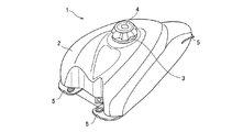
以下に本発明の実施の形態を添付図面に基づいて説明する。ここで、図1は本発明に係るインサート部品溶着成形方法を適用した自動二輪車用燃料タンクの斜視図、図2は給油口本体の側面図、図3は本発明に係るインサート部品溶着成形方法の第1実施の形態を実施する金型構造の概要断面図、図4は第1実施の形態の作用説明図、図5は本発明に係るインサート部品溶着成形方法の第2実施の形態を実施する金型構造の概要断面図、図6は第2実施の形態の作用説明図である。 Embodiments of the present invention will be described below with reference to the accompanying drawings. Here, FIG. 1 is a perspective view of a motorcycle fuel tank to which an insert component welding molding method according to the present invention is applied, FIG. 2 is a side view of a fuel filler body, and FIG. 3 is an insert component welding molding method according to the present invention. 4 is a schematic sectional view of a mold structure for carrying out the first embodiment, FIG. 4 is an operation explanatory view of the first embodiment, and FIG. 5 is a second embodiment of an insert component welding molding method according to the present invention. FIG. 6 is a schematic sectional view of the mold structure, and FIG. 6 is an explanatory diagram of the operation of the second embodiment.
本発明に係るインサート部品溶着成形方法を適用した自動二輪車用燃料タンク1は、図1に示すように、タンク本体2の上面にインサート部品である給油口本体3を溶着している。給油口本体3には、キャップ4が着脱自在に螺合する。
As shown in FIG. 1, a motorcycle fuel tank 1 to which an insert part welding molding method according to the present invention is applied has a
図中5はタンク本体2を車体フレームに取り付けるためのブラケットで、給油口本体3と同様にタンク本体2のブロー成形時にタンク本体2となるパリソンに溶着される。
In the figure, reference numeral 5 denotes a bracket for attaching the
給油口本体3は、図2に示すように、略円筒形状の樹脂製品で、基端部に鍔部6が形成され、外周面にキャップ4と螺合するねじ部3aが形成されている。また、鍔部6の裏面6aには、その厚み方向周縁部6bに近づくに従って薄くなるようにテーパ部6cが形成されている。
As shown in FIG. 2, the fuel filler
本発明に係るインサート部品溶着成形方法の第1実施の形態は、図3に示すように、金型7の成形面7aの一部として配設した予熱板8に給油口本体3をセットする。予熱板8は鍔部6の表面6dと密接することで成形時の押さえ部として機能する。予熱板8には鍔部6の周縁部6bの延長となるように側面8cを立ち上げている。また、金型7と予熱板8の間には温度低下を抑えるための断熱板9が配設されている。
In the first embodiment of the insert part welding molding method according to the present invention, as shown in FIG. 3, the
そして、図4に示すように、金型7内のキャビティに熱可塑性樹脂の予備成形体であるパリソン11を押し込み、パリソン11内に所定圧のエア12を吹き込む(ブロー成形)と、パリソン11が膨らみ、金型7の成形面7a、予熱板8の側面8c、鍔部6の裏面6a、周縁部6b、テーパ部6cに押し付けられる。そして、パリソン11が鍔部6の厚み方向周縁部6bに対し全面が溶着状態になる。
Then, as shown in FIG. 4, when the
尚、側面8cの頂部8dは押付け力不足となるが、インサート部品3との溶着部6bには溶着する圧が十分にかかるので完全な溶着状態になる。
The top 8d of the
このように、パリソン11が鍔部6の厚み方向周縁部6bに対し未溶着部を形成することなく完全な溶着状態になるので、溶着強度(引っ張り強度)の向上、衝撃強度(低温落下衝撃)の向上などを図ることができる。
Thus, since the
本発明に係るインサート部品溶着成形方法の第2実施の形態は、図5に示すように、予熱板8の下面8aは前記金型7の成形面7aよりも一段(H)低くなっている。
In the second embodiment of the insert part welding molding method according to the present invention, the
予熱板8には角度θの傾斜面8bによる高さHの段差10が形成され、傾斜面8bは鍔部6の厚み方向周縁部6bから立ち上がっている(例えば、角度θ=45°、段差の高さH=1mm)。
The preheating
次いで、図6に示すように、金型7内のキャビティに熱可塑性樹脂の予備成形体であるパリソン11を押し込み、パリソン11内に所定圧のエア12を吹き込む(ブロー成形)。すると、パリソン11が膨らみ、金型7の成形面7a、予熱板8の傾斜面8b、鍔部6の裏面6a、周縁部6b、テーパ部6cに押し付けられる。
Next, as shown in FIG. 6, a
ここで、鍔部6の裏面6a、周縁部6b、テーパ部6cはパリソン11との溶着面になる。この溶着面が金型7の成形面7aよりも低くなるように設計することで、パリソン11が鍔部6の厚み方向周縁部6bからテーパ部6c、そして裏面6aにかけて、タンク本体2となるパリソン11と鍔部6が溶着状態になる。特に、周縁部6bの部分にもパリソン11が押し付けられる圧力がかかるので完全な溶着状態になる。
Here, the
このように、パリソン11が鍔部6の厚み方向周縁部6bと未溶着部を形成することなく完全な溶着状態になるので、溶着強度(引っ張り強度)の向上、衝撃強度(低温落下衝撃)の向上などを図ることができる。
Thus, since the
本発明によれば、インサート部品の厚み方向周縁部にブロー成形体との未溶着部分を生じさせることなく、ブロー成形体にインサート部品を確実に溶着させることができるインサート部品溶着成形方法を提供することができる。
According to the present invention, there is provided an insert component welding molding method capable of reliably welding an insert component to a blow molded body without causing an unwelded portion with the blow molded body at a peripheral edge portion in the thickness direction of the insert component. be able to.
1…自動二輪車用燃料タンク、2…タンク本体(ブロー成形体)、3…給油口本体(インサート部品)、3a…ねじ部、4…キャップ、6…鍔部、6a…裏面、6b…厚み方向周縁部、6c…テーパ部、6d…上面、7…金型、7a…成形面、8…予熱板、8a…傾斜面、8b…下面、8c…側面、9…断熱板、10…段差、11…パリソン、12…エア。 DESCRIPTION OF SYMBOLS 1 ... Motorcycle fuel tank, 2 ... Tank main body (blow molding), 3 ... Fuel supply port main body (insert part), 3a ... Screw part, 4 ... Cap, 6 ... Gutter part, 6a ... Back surface, 6b ... Thickness direction Peripheral part, 6c ... tapered part, 6d ... upper surface, 7 ... mold, 7a ... molding surface, 8 ... preheating plate, 8a ... inclined surface, 8b ... lower surface, 8c ... side surface, 9 ... heat insulating plate, 10 ... step, 11 ... Parison, 12 ... Air.
Claims (3)
前記インサート部品の溶着面をインサート部品の周囲の金型成形面よりも低くして、前記インサート部品の溶着面とインサート部品の周囲の金型成形面を結ぶ面をインサート部品にオーバーハングさせることなくインサート部品の厚み方向周縁部6bから立ち上げ、前記インサート部品の厚み方向周縁部6bの全面と前記ブロー成形体のパリソンとを隙間なく溶着状態にすることを特徴とする燃料タンクのインサート部品溶着成形方法。 A fuel tank insert part welding molding method for welding a blow molded article having a multilayer structure to an insert part set in a mold,
The welding surface of the insert part is made lower than the mold forming surface around the insert part, and the surface connecting the weld surface of the insert part and the mold forming surface around the insert part is not overhanged on the insert part. Insert part welding molding of a fuel tank, characterized in that it is raised from a peripheral edge part 6b in the thickness direction of the insert part, and the entire surface of the peripheral edge part 6b in the thickness direction of the insert part and the parison of the blow molded body are welded without gaps. Method.
前記インサート部品の溶接面とインサート部品の周囲のブロー成形体の表面を結ぶ面をインサート部品にオーバーハングさせることなくインサート部品の厚み方向周縁部6bから立ち上げたことを特徴とする燃料タンク。 A fuel tank obtained by supplying gas into a multi-layered parison set in a mold, and an insert part is integrally welded to a part of the fuel tank , and the weld surface of the insert part is an insert It is lower than the surface of the blow molded body around the part ,
A fuel tank, wherein a surface connecting the weld surface of the insert part and the surface of the blow molded body around the insert part is raised from the peripheral edge 6b in the thickness direction of the insert part without overhanging the insert part .
Priority Applications (4)
| Application Number | Priority Date | Filing Date | Title |
|---|---|---|---|
| JP2008176964A JP4837707B2 (en) | 2008-04-16 | 2008-07-07 | Insert part welding method for fuel tank and fuel tank |
| PCT/JP2009/000523 WO2009128190A1 (en) | 2008-04-16 | 2009-02-10 | Method for fusion molding insert part |
| US12/988,214 US8652383B2 (en) | 2008-04-16 | 2009-02-10 | Insert part weld molding method |
| CN200980113751.1A CN102006983B (en) | 2008-04-16 | 2009-02-10 | Fuel tank insert part weld molding method and fuel tank |
Applications Claiming Priority (3)
| Application Number | Priority Date | Filing Date | Title |
|---|---|---|---|
| JP2008106286 | 2008-04-16 | ||
| JP2008106286 | 2008-04-16 | ||
| JP2008176964A JP4837707B2 (en) | 2008-04-16 | 2008-07-07 | Insert part welding method for fuel tank and fuel tank |
Publications (3)
| Publication Number | Publication Date |
|---|---|
| JP2009274429A JP2009274429A (en) | 2009-11-26 |
| JP2009274429A5 JP2009274429A5 (en) | 2010-10-21 |
| JP4837707B2 true JP4837707B2 (en) | 2011-12-14 |
Family
ID=41198902
Family Applications (1)
| Application Number | Title | Priority Date | Filing Date |
|---|---|---|---|
| JP2008176964A Expired - Fee Related JP4837707B2 (en) | 2008-04-16 | 2008-07-07 | Insert part welding method for fuel tank and fuel tank |
Country Status (4)
| Country | Link |
|---|---|
| US (1) | US8652383B2 (en) |
| JP (1) | JP4837707B2 (en) |
| CN (1) | CN102006983B (en) |
| WO (1) | WO2009128190A1 (en) |
Families Citing this family (6)
| Publication number | Priority date | Publication date | Assignee | Title |
|---|---|---|---|---|
| JP5734510B1 (en) * | 2013-08-01 | 2015-06-17 | 株式会社利川プラスチック | Synthetic resin container manufacturing method |
| USD737192S1 (en) * | 2014-01-28 | 2015-08-25 | Paul Yaffe | Motorcycle fuel tank |
| USD852847S1 (en) * | 2014-02-17 | 2019-07-02 | Harley-Davidson Motor Company Group, LLC | Motor of a vehicle |
| EP3000583A1 (en) * | 2014-09-29 | 2016-03-30 | Inergy Automotive Systems Research (Société Anonyme) | Vehicle component with heat shield and method for manufacturing the same |
| US10220553B2 (en) | 2016-10-20 | 2019-03-05 | Bose Corporation | Method of making an item and item |
| CN109515426B (en) * | 2018-12-25 | 2023-10-03 | 浙江乔士智能工业股份有限公司 | Three-section type brake oilcan |
Family Cites Families (27)
| Publication number | Priority date | Publication date | Assignee | Title |
|---|---|---|---|---|
| US3334771A (en) * | 1964-07-06 | 1967-08-08 | Phillips Petroleum Co | Plastic container with metal reinforced inlet and process of making same |
| DE2825097C2 (en) * | 1978-06-08 | 1982-06-09 | K. Kurz Hessental KG, 7170 Schwäbisch Hall | Method for molding a connecting ring into the wall of a container made of thermoplastic material |
| WO1980000326A1 (en) * | 1978-07-28 | 1980-03-06 | Transformat Mat Plastiques | Method for obtaining a one piece cast hollow body by blowing |
| JPS5957724A (en) * | 1982-09-29 | 1984-04-03 | Hashimoto Forming Co Ltd | Manufacture of molding with identification part |
| JPS59143714A (en) * | 1983-02-07 | 1984-08-17 | Nippon Denso Co Ltd | Damper driving device |
| JPS59143714U (en) * | 1983-03-17 | 1984-09-26 | 日産自動車株式会社 | Blow molding mold structure |
| JPS60234823A (en) * | 1984-05-08 | 1985-11-21 | Ishikawajima Harima Heavy Ind Co Ltd | Method for mounting internal insert in blow molding |
| JPS62126923A (en) * | 1985-11-28 | 1987-06-09 | 図師 和彦 | Method for purifying deposited mud of eel breeding basin |
| JPS62126923U (en) * | 1986-02-03 | 1987-08-12 | ||
| JP2621071B2 (en) * | 1988-06-15 | 1997-06-18 | 株式会社イノアックコーポレーション | Blow molded product and method for producing the same |
| JPH03143616A (en) * | 1989-10-31 | 1991-06-19 | Toyoda Gosei Co Ltd | Manufacture of blow product |
| US5103865A (en) * | 1991-07-15 | 1992-04-14 | Ford Motor Company | Integrally molded vapor vent valve |
| RO117437B1 (en) * | 1993-11-19 | 2002-03-29 | S.C. "Moldoplast" S.A. | Process for manufacturing subassemblies meant for fuel tanks or other kind of tanks for special use |
| JPH07178765A (en) * | 1993-12-22 | 1995-07-18 | Asahi Chem Ind Co Ltd | Insert molding method |
| JPH08268057A (en) * | 1995-03-28 | 1996-10-15 | Hayashi Gijutsu Kenkyusho:Kk | Method for forming sun visor having mirror, and sun visor |
| JPH09290814A (en) * | 1996-04-24 | 1997-11-11 | Kioritz Corp | Liquid tank with nipple |
| JP3776221B2 (en) * | 1997-11-05 | 2006-05-17 | 株式会社イノアックコーポレーション | Blow molded product and method for producing the same |
| JP2000108196A (en) * | 1998-10-09 | 2000-04-18 | Nippon Dennetsu Co Ltd | Method for holding blow molding tank |
| US6415941B1 (en) * | 1998-10-09 | 2002-07-09 | Moeller Marine Products | Method of making a fuel tank assembly |
| JP2003225941A (en) * | 2002-02-05 | 2003-08-12 | Yazaki:Kk | Holding fixture for fusion-bonded insert at the time of molding |
| JP2003236920A (en) * | 2002-02-13 | 2003-08-26 | Yazaki:Kk | Insert part fusion-bonding molding method to blow molded object |
| JP2004189235A (en) * | 2002-12-06 | 2004-07-08 | Yachiyo Industry Co Ltd | Lid fitting structure of fuel tank |
| JP2005335464A (en) * | 2004-05-25 | 2005-12-08 | Honda Motor Co Ltd | Vehicular fuel feed structure |
| JP2006022900A (en) * | 2004-07-08 | 2006-01-26 | Nhk Spring Co Ltd | Gasket material, manufacturing method of gasket material, and mounting method of gasket |
| US7476354B2 (en) * | 2004-09-22 | 2009-01-13 | Clack Corporation | Method and apparatus for making a blow molded article with integral insert |
| US20090218845A1 (en) * | 2006-01-06 | 2009-09-03 | Johnson Controls Technology Company | Visor and method of making a visor |
| JP5110508B2 (en) * | 2007-05-16 | 2012-12-26 | 本田技研工業株式会社 | Blow molding equipment |
-
2008
- 2008-07-07 JP JP2008176964A patent/JP4837707B2/en not_active Expired - Fee Related
-
2009
- 2009-02-10 US US12/988,214 patent/US8652383B2/en active Active
- 2009-02-10 CN CN200980113751.1A patent/CN102006983B/en not_active Expired - Fee Related
- 2009-02-10 WO PCT/JP2009/000523 patent/WO2009128190A1/en active Application Filing
Also Published As
| Publication number | Publication date |
|---|---|
| US20110037203A1 (en) | 2011-02-17 |
| CN102006983B (en) | 2015-01-14 |
| CN102006983A (en) | 2011-04-06 |
| WO2009128190A1 (en) | 2009-10-22 |
| US8652383B2 (en) | 2014-02-18 |
| JP2009274429A (en) | 2009-11-26 |
Similar Documents
| Publication | Publication Date | Title |
|---|---|---|
| JP4837707B2 (en) | Insert part welding method for fuel tank and fuel tank | |
| JP5270911B2 (en) | Automotive fuel tank | |
| JP2009274429A5 (en) | ||
| JP5495873B2 (en) | Automotive fuel tank | |
| US9399326B2 (en) | Method for fastening an accessory in a plastic fuel tank | |
| JP2006192919A (en) | Fuel tank for automobile and its manufacturing method | |
| WO2014122747A1 (en) | Automobile fuel tank | |
| JP5877577B2 (en) | Automotive fuel tank | |
| JP2008524014A (en) | Method for producing multilayer hollow body including at least one weld | |
| JP2008155587A (en) | Manufacturing method of hollow resin molded product | |
| JP2009234403A (en) | Resin made fuel tank structure on vehicle | |
| JP2008155588A (en) | Hollow resin molded product and its manufacturing method | |
| TW200302771A (en) | Method of forming fusion insert part in blow molding body | |
| JP4959380B2 (en) | Blow molding spoiler with insert and blow molding spoiler with insert | |
| JP7373065B2 (en) | Plastic containers for liquids and methods for manufacturing plastic containers | |
| JP7215712B2 (en) | Manufacturing method of tank with manhole and manhole body | |
| JP2013119342A (en) | Component welding structure of fuel tank | |
| JP2016117260A (en) | Mounting structure for built-in component of blow molded article | |
| JP2016020061A (en) | Blow molded product | |
| JP4606154B2 (en) | Automotive fuel tank | |
| JP6138749B2 (en) | Synthetic resin tank and manufacturing method thereof | |
| JP6359844B2 (en) | Fuel tank parts welding equipment | |
| JP2019064323A (en) | Resin fuel tank | |
| KR101961118B1 (en) | Plastic fuel tank for vehicle | |
| JP6552576B2 (en) | Resin tank |
Legal Events
| Date | Code | Title | Description |
|---|---|---|---|
| A521 | Written amendment |
Free format text: JAPANESE INTERMEDIATE CODE: A523 Effective date: 20100907 |
|
| A131 | Notification of reasons for refusal |
Free format text: JAPANESE INTERMEDIATE CODE: A131 Effective date: 20110712 |
|
| A521 | Written amendment |
Free format text: JAPANESE INTERMEDIATE CODE: A523 Effective date: 20110907 |
|
| TRDD | Decision of grant or rejection written | ||
| A01 | Written decision to grant a patent or to grant a registration (utility model) |
Free format text: JAPANESE INTERMEDIATE CODE: A01 Effective date: 20110920 |
|
| A01 | Written decision to grant a patent or to grant a registration (utility model) |
Free format text: JAPANESE INTERMEDIATE CODE: A01 |
|
| A61 | First payment of annual fees (during grant procedure) |
Free format text: JAPANESE INTERMEDIATE CODE: A61 Effective date: 20110928 |
|
| FPAY | Renewal fee payment (event date is renewal date of database) |
Free format text: PAYMENT UNTIL: 20141007 Year of fee payment: 3 |
|
| R150 | Certificate of patent or registration of utility model |
Ref document number: 4837707 Country of ref document: JP Free format text: JAPANESE INTERMEDIATE CODE: R150 Free format text: JAPANESE INTERMEDIATE CODE: R150 |
|
| LAPS | Cancellation because of no payment of annual fees |