従来のインサート部品溶着成形方法においては、燃料タンクのブロー成形時にインサート部品を金型へセットし、金型閉め時にパリソンをインサート部品の溶着座に密着させ溶着させている。
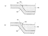
しかし、図7に示すように、インサート部品100の厚み方向周縁部に立壁101があり、パリソン102と溶着しない箇所103が存在する場合がある。また、インサート部品の厚み方向周縁部の溶着を向上させるため、インサート部品の予熱温度や予熱板温度を夫々高めに温度設定するとインサート部品が溶けて成型不良になってしまう。
In the conventional insert part welding molding method, the insert part is set in the mold when the fuel tank is blow-molded, and the parison is brought into close contact with the insert part welding seat when the mold is closed.
However, as shown in FIG. 7, there is a case where there is a standing wall 101 at the peripheral edge in the thickness direction of the insert part 100 and there is a portion 103 that is not welded to the parison 102. Moreover, in order to improve the welding of the peripheral part in the thickness direction of the insert part, if the preheating temperature or the preheating plate temperature of the insert part is set higher, the insert part melts and defective molding occurs.
本発明は、従来の技術が有するこのような問題点に鑑みてなされたものであり、その目的とするところは、インサート部品の厚み方向周縁部に未溶着部分が発生することなく、ブロー成形体にインサート部品が確実に溶着するインサート部品溶着成形方法を提供しようとするものである。
The present invention has been made in view of such problems of the prior art, and the object of the present invention is to provide a blow-molded body without generating an unwelded portion in the peripheral portion in the thickness direction of the insert part. It is an object of the present invention to provide an insert part welding molding method in which an insert part is reliably welded.
上記課題を解決すべく請求項1に係る発明は、金型内にセットしたインサート部品にブロー成形体を溶着するインサート部品溶着成形方法であって、前記金型の成形面を前記インサート部品の被溶着部の表面より高くして、前記インサート部品の厚み方向周縁部の全面と前記ブロー成形体のパリソンとを隙間なく溶着状態にするものである。
In order to solve the above-mentioned problem, the invention according to claim 1 is an insert part welding molding method in which a blow molded body is welded to an insert part set in a mold, the molding surface of the mold being covered with the insert part. The height is higher than the surface of the welded portion, and the entire surface of the peripheral part in the thickness direction of the insert part and the parison of the blow-molded product are welded without a gap.
請求項2に係る発明は、請求項1記載のインサート部品溶着成形方法において、前記パリソンが前記インサート部品の厚み方向周縁部に対してオーバハング(被り)状態で溶着するものである。
According to a second aspect of the present invention, in the insert part welding molding method according to the first aspect, the parison is welded in an overhang (cover) state with respect to a peripheral edge portion in the thickness direction of the insert part.
請求項3に係る発明は、請求項1又は請求項2記載のインサート部品溶着成形方法において、前記パリソンと前記インサート部品の厚み方向周縁部との溶着部近傍に、前記金型の成形面の一部となる高熱伝導材製の予熱板を配設すると共に、この予熱板と前記金型との間に断熱板を設けたものである。
According to a third aspect of the present invention, there is provided the insert part welding molding method according to the first or second aspect, wherein a molding surface of the mold is disposed in the vicinity of the welded portion between the parison and the peripheral edge in the thickness direction of the insert part. A preheating plate made of a high heat conductive material to be a part is disposed, and a heat insulating plate is provided between the preheating plate and the mold.
請求項4に係る発明は、請求項3記載のインサート部品溶着成形方法において、前記予熱板には傾斜面による段差が形成され、この傾斜面による段差により前記パリソンが前記インサート部品の厚み方向周縁部に対してオーバハング状態になるものである。
According to a fourth aspect of the present invention, in the insert part welding molding method according to the third aspect of the present invention, the preheating plate is formed with a step due to an inclined surface, and the step due to the inclined surface causes the parison to have a circumferential edge in the thickness direction of the insert component. Is overhanging.
請求項1に係る発明によれば、インサート部品の厚み方向周縁部にブロー成形体との未溶着部分が発生することなく、ブロー成形体にインサート部品の厚み方向周縁部を確実に溶着することができる。
According to the first aspect of the present invention, it is possible to reliably weld the peripheral portion in the thickness direction of the insert part to the blow molded body without generating an unwelded portion with the blow molded body in the peripheral portion of the insert part in the thickness direction. it can.
請求項2に係る発明によれば、パリソンがインサート部品の厚み方向周縁部に対してオーバハング状態で溶着するため、ブロー成形体がインサート部品の周縁部を包み込むようになり、ブロー成形体にインサート部品を確実に溶着することができる。
According to the invention of claim 2, since the parison is welded to the peripheral edge of the insert part in the thickness direction, the blow molded body wraps around the peripheral edge of the insert part. Can be reliably welded.
請求項3に係る発明によれば、熱伝導の優れた予熱板と温度低下を抑える断熱板により、インサート部品のブロー成形体への溶着を確実なものとすることができる。
According to the invention of claim 3, it is possible to ensure the welding of the insert part to the blow molded body by the preheating plate having excellent heat conduction and the heat insulating plate that suppresses the temperature drop.
請求項4に係る発明によれば、予熱板の傾斜面による段差により、パリソンがインサート部品の厚み方向周縁部に対してオーバハング状態になるため、ブロー成形体がインサート部品の周縁部を包み込むようになり、ブロー成形体にインサート部品を確実に溶着することができる。
According to the invention which concerns on Claim 4, since a parison will be in an overhang state with respect to the thickness direction peripheral part of an insert part by the level | step difference by the inclined surface of a preheating board, it is set so that a blow molded body may wrap the peripheral part of an insert part. Thus, the insert part can be reliably welded to the blow molded body.
以下に本発明の実施の形態を添付図面に基づいて説明する。ここで、図1は本発明に係るインサート部品溶着成形方法を適用した自動二輪車用燃料タンクの斜視図、図2は給油口本体の側面図、図3は本発明に係るインサート部品溶着成形方法の第1実施の形態を実施する金型構造の概要断面図、図4は第1実施の形態の作用説明図、図5は本発明に係るインサート部品溶着成形方法の第2実施の形態を実施する金型構造の概要断面図、図6は第2実施の形態の作用説明図である。
Hereinafter, embodiments of the present invention will be described with reference to the accompanying drawings. Here, FIG. 1 is a perspective view of a motorcycle fuel tank to which an insert component welding molding method according to the present invention is applied, FIG. 2 is a side view of a fuel filler body, and FIG. 3 is an insert component welding molding method according to the present invention. 4 is a schematic sectional view of a mold structure for carrying out the first embodiment, FIG. 4 is an operation explanatory view of the first embodiment, and FIG. 5 is a second embodiment of an insert component welding molding method according to the present invention. FIG. 6 is a schematic sectional view of the mold structure, and FIG. 6 is an explanatory diagram of the operation of the second embodiment.
本発明に係るインサート部品溶着成形方法を適用した自動二輪車用燃料タンク1は、図1に示すように、タンク本体2の頂にインサート部品である給油口本体3を溶着している。給油口本体3には、キャップ4が着脱自在に螺合する。5はタンク本体2を車体フレームに取り付けるためのブラケットで、給油口本体3と同様にタンク本体2のブロー成形時にタンク本体2となるパリソンに溶着される。
Referring to FIG. 1, a motorcycle fuel tank 1 to which an insert part welding molding method according to the present invention is applied has a fuel filler body 3 as an insert part welded to the top of a tank body 2. A cap 4 is detachably screwed into the fuel filler body 3. Reference numeral 5 denotes a bracket for attaching the tank main body 2 to the vehicle body frame, and is welded to a parison that becomes the tank main body 2 when the tank main body 2 is blow-molded, like the fuel filler main body 3.
給油口本体3は、図2に示すように、略円筒形状の樹脂製品で、基端部に鍔部6が形成され、外周面にキャップ4と螺合するねじ部3aが形成されている。また、鍔部6の裏面6aには、その厚み方向周縁部6bに近づくに従って薄くなるようにテーパ部6cが形成されている。
As shown in FIG. 2, the fuel filler main body 3 is a substantially cylindrical resin product. A flange portion 6 is formed at the base end portion, and a screw portion 3 a that is screwed with the cap 4 is formed on the outer peripheral surface. Moreover, the taper part 6c is formed in the back surface 6a of the collar part 6 so that it may become thin as it approaches the thickness direction peripheral part 6b.
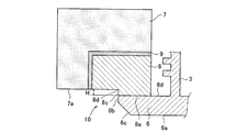
本発明に係るインサート部品溶着成形方法の第1実施の形態は、図3に示すように、金型7の成形面7aの一部として配設した予熱板8に給油口本体3をセットする。予熱板8は鍔部6の表面6dと密接するように配設されている。予熱板8には角度θの傾斜面8aによる高さHの段差10が形成され、傾斜面8aは鍔部6の厚み方向周縁部6bから立ち上がっている(例えば、角度θ=45°、段差の高さH=1mm)。また、金型7と予熱板8の間には温度低下を抑えるための断熱板9が配設されている。
In the first embodiment of the insert part welding molding method according to the present invention, as shown in FIG. 3, the fuel filler body 3 is set on a preheating plate 8 disposed as a part of the molding surface 7 a of the mold 7. The preheating plate 8 is disposed so as to be in close contact with the surface 6 d of the flange portion 6. The preheating plate 8 is formed with a step 10 having a height H by an inclined surface 8a having an angle θ, and the inclined surface 8a rises from a peripheral edge 6b in the thickness direction of the flange 6 (for example, an angle θ = 45 °, Height H = 1 mm). Further, a heat insulating plate 9 is provided between the mold 7 and the preheating plate 8 to suppress a temperature drop.
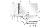
次いで、図4に示すように、金型7内のキャビティに熱可塑性樹脂の予備成形体であるパリソン11を押し込み、パリソン11内に所定圧のエア12を吹き込む(ブロー成形)。すると、パリソン11が膨らみ、金型7の成形面7a、予熱板8の傾斜面8aや鍔部6の裏面6aなどに押し付けられる。そして、パリソン11が鍔部6の厚み方向周縁部6bからテーパ部6c、そして裏面6aにかけて、タンク本体2となるパリソン11と鍔部6が完全な溶着状態になる。
Next, as shown in FIG. 4, the parison 11 which is a thermoplastic resin preform is pushed into the cavity of the mold 7, and air 12 having a predetermined pressure is blown into the parison 11 (blow molding). Then, the parison 11 swells and is pressed against the molding surface 7 a of the mold 7, the inclined surface 8 a of the preheating plate 8, the back surface 6 a of the flange 6, and the like. And the parison 11 used as the tank main body 2 and the collar part 6 will be in a perfect welding state from the thickness direction peripheral part 6b of the collar part 6 to the taper part 6c and the back surface 6a.
このように、パリソン11が鍔部6の厚み方向周縁部6bと未溶着部を形成することなく完全な溶着状態になるので、溶着強度(引っ張り強度)の向上、衝撃強度(低温落下衝撃)の向上などを図ることができる。
Thus, since the parison 11 is in a completely welded state without forming the unwelded portion with the thickness direction peripheral edge portion 6b of the flange portion 6, the weld strength (tensile strength) is improved and the impact strength (low temperature drop impact) is improved. Improvements can be made.
本発明に係るインサート部品溶着成形方法の第2実施の形態は、図5に示すように、金型7の成形面7aの一部として配設した予熱板8に給油口本体3をセットする。予熱板8は鍔部6の表面6dと密接するように配設されている。予熱板8には角度θの傾斜面8aによる高さHの段差10が形成され、傾斜面8aは鍔部6の厚み方向周縁部6bから距離Dだけ給油口本体3の中心軸側から立ち上がっている(例えば、角度θ=45°、段差の高さH=1mm、距離D=0.5mm)。また、金型7と予熱板8の間には温度低下を抑えるための断熱板9が配設されている。
In the second embodiment of the insert part welding molding method according to the present invention, as shown in FIG. 5, the fuel filler body 3 is set on a preheating plate 8 disposed as a part of the molding surface 7 a of the mold 7. The preheating plate 8 is disposed so as to be in close contact with the surface 6 d of the flange portion 6. The preheating plate 8 is formed with a step 10 having a height H due to an inclined surface 8a having an angle θ, and the inclined surface 8a rises from the central axis side of the fuel filler main body 3 by a distance D from the peripheral edge 6b in the thickness direction of the flange portion 6. (For example, angle θ = 45 °, step height H = 1 mm, distance D = 0.5 mm). Further, a heat insulating plate 9 is provided between the mold 7 and the preheating plate 8 to suppress a temperature drop.
次いで、図6に示すように、金型7内のキャビティに熱可塑性樹脂の予備成形体であるパリソン11を押し込み、パリソン11内に所定圧のエア12を吹き込む(ブロー成形)。すると、パリソン11が膨らみ、金型7の成形面7a、予熱板8の傾斜面8aや鍔部6の裏面6aなどに押し付けられる。そして、パリソン11が鍔部6の厚み方向周縁部6bに対しオーバハング状態になって被り部11aが形成され、鍔部6の厚み方向周縁部6b近傍の表面6d、厚み方向周縁部6bからテーパ部6c、そして裏面6aにかけて、タンク本体2となるパリソン11と鍔部6が完全な溶着状態になる。
Next, as shown in FIG. 6, the parison 11, which is a thermoplastic resin preform, is pushed into the cavity of the mold 7, and air 12 having a predetermined pressure is blown into the parison 11 (blow molding). Then, the parison 11 swells and is pressed against the molding surface 7 a of the mold 7, the inclined surface 8 a of the preheating plate 8, the back surface 6 a of the flange 6, and the like. Then, the parison 11 is overhanged with respect to the peripheral edge 6b in the thickness direction of the flange 6 to form a covering portion 11a. The surface 6d in the vicinity of the peripheral edge 6b in the thickness direction of the flange 6 is tapered from the peripheral edge 6b in the thickness direction. 6 c and the back surface 6 a, the parison 11 that becomes the tank body 2 and the flange portion 6 are completely welded.
このように、パリソン11が鍔部6の厚み方向周縁部6bに対しオーバハング状態になって被り部11aが形成されると共に、鍔部6の厚み方向周縁部6bとパリソン11とが未溶着部を形成することなく完全な溶着状態になるので、溶着強度(引っ張り強度)の向上、衝撃強度(低温落下衝撃)の向上などを図ることができる。
In this way, the parison 11 is overhanged with respect to the thickness direction peripheral portion 6b of the flange portion 6 to form the covering portion 11a, and the thickness direction peripheral portion 6b of the flange portion 6 and the parison 11 serve as unwelded portions. Since it is in a completely welded state without being formed, it is possible to improve the welding strength (tensile strength), the impact strength (low temperature drop impact), and the like.