JP4823367B2 - Method for forming member having undercut portion - Google Patents
Method for forming member having undercut portion Download PDFInfo
- Publication number
- JP4823367B2 JP4823367B2 JP2010023774A JP2010023774A JP4823367B2 JP 4823367 B2 JP4823367 B2 JP 4823367B2 JP 2010023774 A JP2010023774 A JP 2010023774A JP 2010023774 A JP2010023774 A JP 2010023774A JP 4823367 B2 JP4823367 B2 JP 4823367B2
- Authority
- JP
- Japan
- Prior art keywords
- mandrel
- diameter
- undercut
- concave portion
- forming
- Prior art date
- Legal status (The legal status is an assumption and is not a legal conclusion. Google has not performed a legal analysis and makes no representation as to the accuracy of the status listed.)
- Expired - Fee Related
Links
Images


Classifications
-
- F—MECHANICAL ENGINEERING; LIGHTING; HEATING; WEAPONS; BLASTING
- F02—COMBUSTION ENGINES; HOT-GAS OR COMBUSTION-PRODUCT ENGINE PLANTS
- F02M—SUPPLYING COMBUSTION ENGINES IN GENERAL WITH COMBUSTIBLE MIXTURES OR CONSTITUENTS THEREOF
- F02M61/00—Fuel-injectors not provided for in groups F02M39/00 - F02M57/00 or F02M67/00
- F02M61/16—Details not provided for in, or of interest apart from, the apparatus of groups F02M61/02 - F02M61/14
- F02M61/168—Assembling; Disassembling; Manufacturing; Adjusting
-
- B—PERFORMING OPERATIONS; TRANSPORTING
- B21—MECHANICAL METAL-WORKING WITHOUT ESSENTIALLY REMOVING MATERIAL; PUNCHING METAL
- B21C—MANUFACTURE OF METAL SHEETS, WIRE, RODS, TUBES OR PROFILES, OTHERWISE THAN BY ROLLING; AUXILIARY OPERATIONS USED IN CONNECTION WITH METAL-WORKING WITHOUT ESSENTIALLY REMOVING MATERIAL
- B21C23/00—Extruding metal; Impact extrusion
- B21C23/02—Making uncoated products
- B21C23/04—Making uncoated products by direct extrusion
- B21C23/14—Making other products
-
- B—PERFORMING OPERATIONS; TRANSPORTING
- B21—MECHANICAL METAL-WORKING WITHOUT ESSENTIALLY REMOVING MATERIAL; PUNCHING METAL
- B21J—FORGING; HAMMERING; PRESSING METAL; RIVETING; FORGE FURNACES
- B21J5/00—Methods for forging, hammering, or pressing; Special equipment or accessories therefor
- B21J5/06—Methods for forging, hammering, or pressing; Special equipment or accessories therefor for performing particular operations
-
- B—PERFORMING OPERATIONS; TRANSPORTING
- B21—MECHANICAL METAL-WORKING WITHOUT ESSENTIALLY REMOVING MATERIAL; PUNCHING METAL
- B21J—FORGING; HAMMERING; PRESSING METAL; RIVETING; FORGE FURNACES
- B21J7/00—Hammers; Forging machines with hammers or die jaws acting by impact
- B21J7/02—Special design or construction
- B21J7/14—Forging machines working with several hammers
- B21J7/16—Forging machines working with several hammers in rotary arrangements
-
- B—PERFORMING OPERATIONS; TRANSPORTING
- B21—MECHANICAL METAL-WORKING WITHOUT ESSENTIALLY REMOVING MATERIAL; PUNCHING METAL
- B21K—MAKING FORGED OR PRESSED METAL PRODUCTS, e.g. HORSE-SHOES, RIVETS, BOLTS OR WHEELS
- B21K1/00—Making machine elements
- B21K1/20—Making machine elements valve parts
-
- B—PERFORMING OPERATIONS; TRANSPORTING
- B21—MECHANICAL METAL-WORKING WITHOUT ESSENTIALLY REMOVING MATERIAL; PUNCHING METAL
- B21K—MAKING FORGED OR PRESSED METAL PRODUCTS, e.g. HORSE-SHOES, RIVETS, BOLTS OR WHEELS
- B21K21/00—Making hollow articles not covered by a single preceding sub-group
- B21K21/08—Shaping hollow articles with different cross-section in longitudinal direction, e.g. nozzles, spark-plugs
-
- F—MECHANICAL ENGINEERING; LIGHTING; HEATING; WEAPONS; BLASTING
- F02—COMBUSTION ENGINES; HOT-GAS OR COMBUSTION-PRODUCT ENGINE PLANTS
- F02M—SUPPLYING COMBUSTION ENGINES IN GENERAL WITH COMBUSTIBLE MIXTURES OR CONSTITUENTS THEREOF
- F02M2200/00—Details of fuel-injection apparatus, not otherwise provided for
- F02M2200/90—Selection of particular materials
- F02M2200/9007—Ceramic materials
-
- F—MECHANICAL ENGINEERING; LIGHTING; HEATING; WEAPONS; BLASTING
- F02—COMBUSTION ENGINES; HOT-GAS OR COMBUSTION-PRODUCT ENGINE PLANTS
- F02M—SUPPLYING COMBUSTION ENGINES IN GENERAL WITH COMBUSTIBLE MIXTURES OR CONSTITUENTS THEREOF
- F02M2200/00—Details of fuel-injection apparatus, not otherwise provided for
- F02M2200/90—Selection of particular materials
- F02M2200/9038—Coatings
-
- F—MECHANICAL ENGINEERING; LIGHTING; HEATING; WEAPONS; BLASTING
- F02—COMBUSTION ENGINES; HOT-GAS OR COMBUSTION-PRODUCT ENGINE PLANTS
- F02M—SUPPLYING COMBUSTION ENGINES IN GENERAL WITH COMBUSTIBLE MIXTURES OR CONSTITUENTS THEREOF
- F02M2200/00—Details of fuel-injection apparatus, not otherwise provided for
- F02M2200/90—Selection of particular materials
- F02M2200/9046—Multi-layered materials
-
- F—MECHANICAL ENGINEERING; LIGHTING; HEATING; WEAPONS; BLASTING
- F02—COMBUSTION ENGINES; HOT-GAS OR COMBUSTION-PRODUCT ENGINE PLANTS
- F02M—SUPPLYING COMBUSTION ENGINES IN GENERAL WITH COMBUSTIBLE MIXTURES OR CONSTITUENTS THEREOF
- F02M2200/00—Details of fuel-injection apparatus, not otherwise provided for
- F02M2200/90—Selection of particular materials
- F02M2200/9053—Metals
- F02M2200/9076—Non-ferrous metals
-
- Y—GENERAL TAGGING OF NEW TECHNOLOGICAL DEVELOPMENTS; GENERAL TAGGING OF CROSS-SECTIONAL TECHNOLOGIES SPANNING OVER SEVERAL SECTIONS OF THE IPC; TECHNICAL SUBJECTS COVERED BY FORMER USPC CROSS-REFERENCE ART COLLECTIONS [XRACs] AND DIGESTS
- Y10—TECHNICAL SUBJECTS COVERED BY FORMER USPC
- Y10T—TECHNICAL SUBJECTS COVERED BY FORMER US CLASSIFICATION
- Y10T29/00—Metal working
- Y10T29/49—Method of mechanical manufacture
- Y10T29/49229—Prime mover or fluid pump making
- Y10T29/49298—Poppet or I.C. engine valve or valve seat making
- Y10T29/493—Valve guide making
-
- Y—GENERAL TAGGING OF NEW TECHNOLOGICAL DEVELOPMENTS; GENERAL TAGGING OF CROSS-SECTIONAL TECHNOLOGIES SPANNING OVER SEVERAL SECTIONS OF THE IPC; TECHNICAL SUBJECTS COVERED BY FORMER USPC CROSS-REFERENCE ART COLLECTIONS [XRACs] AND DIGESTS
- Y10—TECHNICAL SUBJECTS COVERED BY FORMER USPC
- Y10T—TECHNICAL SUBJECTS COVERED BY FORMER US CLASSIFICATION
- Y10T29/00—Metal working
- Y10T29/49—Method of mechanical manufacture
- Y10T29/49995—Shaping one-piece blank by removing material
- Y10T29/49996—Successive distinct removal operations
Description
本発明は、例えば燃料噴射ノズルのように内周部の一部にアンダーカット部を有する部材の成形方法に関する。 The present invention relates to a method for forming a member having an undercut portion at a part of an inner peripheral portion such as a fuel injection nozzle.
燃料噴射ノズルの一般的な形状を図20に示す。燃料噴射ノズルは軸方向に内径2〜4mmの中空穴が形成され、この中空穴の先端に燃料噴出口が、また中空穴の奥部に燃料溜りとなるアンダーカット部が形成されている。 The general shape of the fuel injection nozzle is shown in FIG. The fuel injection nozzle is formed with a hollow hole with an inner diameter of 2 to 4 mm in the axial direction, a fuel injection port is formed at the tip of the hollow hole, and an undercut part that serves as a fuel reservoir is formed at the back of the hollow hole.
部材の内側部にアンダーカット部を機械加工によって形成できるのは、せいぜい内周部の径が10mmまでであり、燃料噴射ノズルのように内径2〜3mmの中空穴の内周部にアンダーカット部を形成するには従来から電解加工によって形成している。 The undercut part can be formed in the inner part of the member by machining. The diameter of the inner peripheral part is at most 10 mm, and the undercut part is in the inner peripheral part of a hollow hole having an inner diameter of 2 to 3 mm like a fuel injection nozzle. Conventionally, it has been formed by electrolytic processing.
電解加工以外の方法としては、特許文献1〜3に提案される方法がある。特許文献1には、素材をカップ状に成形し、更にこのカップ状素材の上端周縁を外側に膨出させ、外側からダイでしごき加工することで膨出した前記上端周縁を内側に張り出すようにし、結果的に素材内側にアンダーカット部が成形されることが開示されている。
As methods other than electrolytic processing, there are methods proposed in
特許文献2には、上端部の内径が棒状素材よりも大径となったダイに棒状素材を入れ、上方から棒状素材よりも小径のパンチによって棒状素材の上端を加圧し、素材の上端部をダイ形状に倣って拡径するとともに、小径のパンチが棒状素材の上端に進入する際にアンダーカット部が自動的に成形されることが開示されている。
In
特許文献3には、肩部を有するダイに当該肩部に当か接する段部を有する素材をセットし、また素材に形成した袋穴の途中までマンドレルを挿入し、この状態でパンチによって素材を据え込み成形することでダイ上半部内の材料を変形せしめ、同時にダイ下半部では材料の径方向内側への流れを作らずにアンダーカット部とすることが開示されている。
In
また、自動車用エンジンにあっては、吸気弁や排気弁のバルブステムの往復直線動を案内すべく、シリンダヘッドに細い筒状のバルブガイドを取り付けている。このバルブガイドの素材としては一般に鉄の焼結品や銅系合金を用いているが、エンジンの高出力化に伴い、軽量で耐熱性に優れた素材を用いることが提案されている。 In an automobile engine, a thin cylindrical valve guide is attached to a cylinder head in order to guide the reciprocating linear movement of a valve stem of an intake valve or an exhaust valve. As a material for the valve guide, a sintered iron product or a copper-based alloy is generally used. However, as the engine output increases, it has been proposed to use a material that is light in weight and excellent in heat resistance.
また、エンジンのシリンダヘッドに取り付けられるバルブガイドには小径のガイド穴が形成され、このガイド穴に吸気弁や排気弁のバルブステムが挿通され、高速で摺動するとともに高温下で使用される。このため、バルブガイドには耐磨耗性、耐焼付き性、耐スカッフ性及び熱伝導性に優れることが要求される。 Further, a small diameter guide hole is formed in a valve guide attached to the cylinder head of the engine, and a valve stem of an intake valve or an exhaust valve is inserted into the guide hole, and the valve guide slides at a high speed and is used at a high temperature. For this reason, the valve guide is required to have excellent wear resistance, seizure resistance, scuff resistance and thermal conductivity.
上記の特性が要求されるため、バルブガイドの材料としては従来からFe合金の焼結材が用いられてきたが、重量が増すという欠点がある。
そこで、特許文献4では溶融したアルミニウム−珪素合金をガスアトマイズしながら急冷凝固堆積させてインゴットを製造し、このインゴットを押出し成形することで管状とし、これを所定寸法に切断することでバルブガイドとする方法が提案されている。
Since the above characteristics are required, an Fe alloy sintered material has been conventionally used as a material for the valve guide, but there is a disadvantage that the weight increases.
Therefore, in Patent Document 4, a molten aluminum-silicon alloy is rapidly solidified and deposited while gas atomizing to produce an ingot, and this ingot is extruded to form a tubular shape, which is cut into a predetermined dimension to obtain a valve guide. A method has been proposed.
また、特許文献5にはバルブガイドに限定されるものではないが、耐熱強度に優れたアルミニウム合金を製造する方法として、急冷凝固アルミニウム合金粉末を常温以上300℃以下の温度で予備成形して得た成形体を、450℃〜540℃で鍛造する方法が提案されている。
アンダーカット部を有する部材を電解加工によって製造する場合には、洗浄工程が必ず必要になるとともに、研磨などの廃液処理の問題が生じる。
一方、特許文献1〜3にあっては、アンダーカット部を設ける箇所が限定されてしまう。つまり特許文献1では素材全体にアンダーカット部が形成され、特許文献2にあっては素材の上端部に限定され、特許文献3にあっては軸方向に形成した穴の奥部に限定される。
また、特許文献1〜3のいずれも素材自体を屈曲させることでアンダーカット部とするため、アンダーカット部の形状を一定にすることが困難で、製品歩留りも悪い。
When a member having an undercut portion is manufactured by electrolytic processing, a cleaning process is necessarily required, and a problem of waste liquid treatment such as polishing occurs.
On the other hand, in
In addition, since all of
一方バルブガイドに関しては、上述したように、特許文献4や5のようなアトマイズ法によって得た急冷凝固アルミニウム合金粉末は、耐磨耗性、耐熱性および耐焼付き性などに優れるため、これをエンジンのバルブガイドなどの材料として用いれば軽量化が図れる。
On the other hand, regarding the valve guide, as described above, the rapidly solidified aluminum alloy powder obtained by the atomizing method as described in
しかしながら、急冷凝固アルミニウム合金粉末は高価であるばかりでなく、切削加工が困難でバルブガイドのような細径のガイド穴を有する筒状部材の成形には不向きである。つまり、熱間による押出し加工によって製造することになるが、金型の寿命が短くなるとともに加熱のエネルギーも必要となり、設備的にもコスト的にも問題がある。 However, the rapidly solidified aluminum alloy powder is not only expensive, but also difficult to cut and is not suitable for forming a cylindrical member having a small guide hole such as a valve guide. That is, it is manufactured by hot extrusion, but the life of the mold is shortened and heating energy is required, which causes problems in terms of equipment and cost.
上記課題を解決するため本発明は、小径の内径部を有する部材の成形方法であって、この成形方法は素材に大径の凹部を形成し、この凹部に目的とする部材の内周部の径と等しい径のマンドレルを挿入して外側からスウェージング加工するようにした。
即ち、第1発明に係るアンダーカット部を有する部材の成形方法は、以下の工程1〜4を含むことで上記の課題を解決した。
1:部材の内周部よりも大径の凹部を鍛造などによって素材に形成する工程。
2:前記凹部の内周にアンダーカット部を形成する工程。
3:前記アンダーカット部が形成された素材の凹部に目的とする部材の内周部の径と等しい径のマンドレルを挿入する工程。
4:前記マンドレルを挿入した素材の外側からスウェージング加工して前記アンダーカット部を残した状態で素材の前記凹部の内径をマンドレル外径まで縮小する工程。
この後、旋削加工などを行って目的の製品、例えば燃料噴射ノズルの外径形状とする。
In order to solve the above-described problems, the present invention is a method for forming a member having a small-diameter inner diameter portion. The molding method forms a large-diameter recess in a material, and the inner peripheral portion of the target member is formed in the recess. A mandrel having a diameter equal to the diameter was inserted and swaging was performed from the outside.
That is, the method for forming a member having an undercut portion according to the first invention has solved the above problems by including the
1: A step of forming a concave portion having a diameter larger than the inner peripheral portion of the member in the material by forging or the like.
2: The process of forming an undercut part in the inner periphery of the said recessed part.
3: A step of inserting a mandrel having a diameter equal to the diameter of the inner peripheral portion of the target member into the concave portion of the material in which the undercut portion is formed.
4: A step of reducing the inner diameter of the concave portion of the material to the outer diameter of the mandrel while swaging from the outside of the material into which the mandrel is inserted, leaving the undercut portion.
Thereafter, turning is performed to obtain an outer diameter shape of a target product, for example, a fuel injection nozzle.
また、第2発明に係るアンダーカット部を有する部材の成形方法は、部材の内周部よりも大径の凹部を素材に成形し、この凹部の内周にアンダーカット部を形成し、このアンダーカット部が形成された素材の凹部に目的とする部材の内周部の径と等しい径で先端部が円錐形状となったマンドレルを挿入し、このマンドレルを挿入した素材の外側からスウェージング加工することで、前記アンダーカット部を残した状態で素材の前記凹部の内径をマンドレル外径まで縮小せしめ、またこれと同時に前記マンドレルの先端部に倣って目的とする部材の内周部の先端形状を雌テーパ状に成形するようにした。
上記構成とすることで、内周部にアンダーカット部と先端の雌テーパ状部とが同時に成形でき、また、雌テーパ状部の深さがマンドレル先端部の円錐状部の長さに等しいため、後加工における研削代を決める際の長手証が得られる。
Further, a method for forming a member having an undercut portion according to the second aspect of the invention is to form a recess having a larger diameter than the inner peripheral portion of the member into a material, and to form an undercut portion on the inner periphery of the recess. A mandrel having a diameter equal to the diameter of the inner periphery of the target member and a conical tip is inserted into the concave portion of the material where the cut portion is formed, and swaging is performed from the outside of the material into which the mandrel is inserted. By reducing the inner diameter of the concave portion of the material to the outer diameter of the mandrel while leaving the undercut portion, and at the same time, following the tip of the mandrel, the tip shape of the inner peripheral portion of the target member The female taper was formed.
By adopting the above configuration, an undercut portion and a female tapered portion at the tip can be simultaneously formed on the inner peripheral portion, and the depth of the female tapered portion is equal to the length of the conical portion at the tip of the mandrel. Longitudinal evidence for determining the grinding allowance in post-processing can be obtained.
第2発明に係る成形方法にあっては、前記大径の凹部の中心に、マンドレル先端部を差し込む深さはマンドレル先端部の長さと等しいかそれよりも浅く、また位置決め穴の開き角度はマンドレル先端部の角度と等しいかそれよりも大きい寸法の位置決め穴を形成しておくことが好ましい。
このように予め位置決め穴を形成しておくことで、マンドレルの位置がずれることがなくなる。尚、位置決め穴は鍛造成形によって前記凹部を成形する際に同時に成形しておけば効率がよい。
In the molding method according to the second invention, the depth at which the mandrel tip is inserted into the center of the large-diameter recess is equal to or less than the length of the mandrel tip, and the opening angle of the positioning hole is mandrel It is preferable to form a positioning hole having a dimension equal to or larger than the angle of the tip.
By previously forming the positioning holes in this way, the position of the mandrel will not be shifted. In addition, it is efficient if the positioning hole is formed at the same time when the concave portion is formed by forging.
また、第3発明に係るアンダーカット部を有する部材の成形方法は、部材の内周部よりも大径の凹部を素材に成形し、この凹部の内周にアンダーカット部を形成し、このアンダーカット部が形成された素材の凹部に目的とする部材の内周部の径と等しい径のマンドレルを挿入し、このマンドレルを挿入した素材の外側からスウェージング加工して前記アンダーカット部を残した状態で素材の前記凹部の内径をマンドレル外径まで縮小せしめるようにしたアンダーカット部を有する部材の成形方法であって、前記スウェージング加工する前の素材の凹部の底部には面取り部が形成され、この面取り部の形成領域は前記マンドレルの先端を素材の凹部の底部に突き当てた状態でクリアランスとなる外側領域内とした。 According to a third aspect of the present invention, there is provided a method for forming a member having an undercut portion, wherein a concave portion having a diameter larger than the inner peripheral portion of the member is formed into a material, and an undercut portion is formed on the inner periphery of the concave portion. A mandrel having a diameter equal to the diameter of the inner peripheral portion of the target member is inserted into the concave portion of the material in which the cut portion is formed, and the undercut portion is left by swaging from the outside of the material into which the mandrel is inserted. A method of forming a member having an undercut portion in which the inner diameter of the concave portion of the material is reduced to the outer diameter of the mandrel in a state where a chamfered portion is formed at the bottom of the concave portion of the raw material before the swaging process. The formation region of the chamfered portion is set in the outer region that becomes a clearance when the tip of the mandrel is abutted against the bottom of the concave portion of the material.
第3発明に係る成形方法では、スウェージング加工の際には素材が長手方向に沿って開口方向に流動するが、上記構成のように凹部の底部のコーナに面取り部を設けておくと、素材が流動してもコーナ部において材料不足が起きることがなく、欠肉が発生しない。また、前記面取り部を形成領域はマンドレルと凹部内周との間のクリアランスの35%〜100%とすることが好ましい。35%未満では材料不足が起きるおそれがある。100%を超えると、マンドレル先端部と面取り部にかかりマンドレルの位置が安定しない。 In the molding method according to the third aspect of the present invention, the material flows in the opening direction along the longitudinal direction during swaging, but if the chamfered portion is provided in the corner at the bottom of the recess as in the above configuration, the material Even if the material flows, there is no shortage of material in the corner, and no shortage occurs. Moreover, it is preferable that the formation area of the chamfered portion is 35% to 100% of the clearance between the mandrel and the inner periphery of the concave portion. If it is less than 35%, material shortage may occur. If it exceeds 100%, the mandrel tip portion and the chamfered portion are caught and the position of the mandrel is not stable.
また、第4発明に係るアンダーカット部を有する部材の成形方法は、先ず素材に目的とする部材の内周部よりも大径の凹部を成形し、この凹部の内周にアンダーカット部を形成し、このアンダーカット部が形成された素材の凹部に目的とする部材の内周部の径と等しい径のマンドレルを挿入し、このマンドレルを挿入した素材の外側からスウェージング加工して前記アンダーカット部を残した状態で素材の前記凹部の内径をマンドレル外径まで縮小せしめるようにしたアンダーカット部を有する部材の成形方法であって、前記スウェージング加工する前の素材の凹部内周または外周に、凹部の底部から所定長さ範囲において余肉部を予め設けるようにした。
ここで、前記余肉部は鍛造成形によって前記凹部を成形する際に同時に成形するのが効率がよい。
Further, in the method for forming a member having an undercut portion according to the fourth aspect of the invention, first, a concave portion having a larger diameter than the inner peripheral portion of the target member is formed on the material, and the undercut portion is formed on the inner periphery of the concave portion. Then, a mandrel having a diameter equal to the diameter of the inner peripheral portion of the target member is inserted into the concave portion of the material in which the undercut portion is formed, and the undercut is performed by swaging from the outside of the material into which the mandrel is inserted. A method of forming a member having an undercut portion in which the inner diameter of the concave portion of the material is reduced to the outer diameter of the mandrel while leaving the portion, and is formed on the inner periphery or outer periphery of the concave portion of the raw material before the swaging process. The surplus portion is provided in advance within a predetermined length range from the bottom of the recess.
Here, it is efficient to form the surplus portion at the same time when the concave portion is formed by forging.
第1発明によれば、機械加工が困難な内径10mm以下の袋穴などの内周部にもアンダーカット部を形成することができる。また、加工に伴って廃液が生じることがなく、環境衛生上も有利である。また、従来の工程にかかる時間を大幅に短縮することができる。 According to the first invention, an undercut portion can be formed also in an inner peripheral portion such as a bag hole having an inner diameter of 10 mm or less, which is difficult to machine. In addition, no waste liquid is generated during processing, which is advantageous in terms of environmental hygiene. In addition, the time required for the conventional process can be greatly reduced.
更に、アンダーカット部の形状も素材を屈曲させて形成するのではなく、予め機械加工によって形成できるため、その形状が正確である。したがって、燃料噴射ノズルのような正確な形状が要求される部材の成形に適用することで、製品の歩留り向上が図れる。 Furthermore, the shape of the undercut portion is not formed by bending the material, but can be formed by machining in advance, so that the shape is accurate. Therefore, the yield of products can be improved by applying to molding of a member that requires an accurate shape such as a fuel injection nozzle.
第2発明によれば、電解加工と比較して廃液が生じることがなく環境衛生上有利で、またアンダーカット部の形状も予め機械加工によって形成できるため正確で、また、最終形状として機械加工が困難な内径10mm以下の袋穴などの内周部にもアンダーカット部と雌テーパ部同時に形成することができる。特にマンドレル先端が挿入される位置決め穴を予め形成しておくことで、スウェージング加工する際の素材の倒れを防止でき長手証を得ることができる。 According to the second aspect of the invention, there is no waste liquid as compared with electrolytic processing, which is advantageous in terms of environmental hygiene, and the shape of the undercut portion can be formed by machining in advance. An undercut portion and a female taper portion can be formed at the same time in an inner peripheral portion such as a bag hole having an inner diameter of 10 mm or less, which is difficult. In particular, by forming a positioning hole into which the mandrel tip is inserted in advance, it is possible to prevent the material from falling down during the swaging process and obtain a longitudinal certificate.
第3発明によれば、電解加工と比較して廃液が生じることがなく環境衛生上有利で、またアンダーカット部の形状も予め機械加工によって形成できるため正確で、また、最終形状として機械加工が困難な内径10mm以下の袋穴などの内周部にもアンダーカット部を形成することができる。特にスウェージング加工する前の素材の凹部の底部に面取り部を形成しておくことで、スウェージング加工する際の材料不足を当該面取り部の材料で補うことができ、欠肉の発生を防止できる。 According to the third invention, there is no waste liquid as compared with electrolytic machining, which is advantageous in terms of environmental hygiene, and the shape of the undercut portion can be formed by machining in advance, and is accurate, and machining as the final shape is possible. An undercut portion can also be formed in an inner peripheral portion such as a bag hole having a difficult inner diameter of 10 mm or less. In particular, by forming a chamfered portion at the bottom of the concave portion of the raw material before swaging, the material shortage during swaging can be compensated with the material of the chamfered portion, and the occurrence of lacking can be prevented. .
第4発明によれば、電解加工と比較して廃液が生じることがなく環境衛生上有利で、またアンダーカット部の形状も予め機械加工によって形成できるため正確で、また、最終形状として機械加工が困難な内径10mm以下の袋穴などの内周部にもアンダーカット部を形成することがでる。特に余肉部を設けることでスウェージング加工する際の材料不足を補うことができ、欠肉の発生を防止できる。 According to the fourth aspect of the invention, there is no waste liquid as compared with electrolytic processing, which is advantageous in terms of environmental hygiene, and the shape of the undercut portion can be formed by machining in advance, which is accurate, and machining as the final shape is possible. Undercut portions can also be formed on inner peripheral portions such as bag holes having an inner diameter of 10 mm or less which are difficult. In particular, providing a surplus portion can compensate for a material shortage during the swaging process, and can prevent the occurrence of a shortage.
以下に具体的な実施例を添付図面に基づいて説明する。
(第1発明)
Specific embodiments will be described below with reference to the accompanying drawings.
(First invention)
先ず、図1(a)に示すビレットを切断して棒状素材1を用意する。この棒状素材としてはSCM415等が適当である。
First, a
この後、図1(b)に示すように、冷間鍛造(前方押出し又は後方押出し)にて前記棒状素材1に凹部2を形成する。この凹部2は後に製品の内周部になる部分であるが、その径は製品の内周部よりも大きく、十分に機械加工が可能な大きさ(10mm以上)とする。
Thereafter, as shown in FIG. 1 (b), the
次いで、図1(c)に示すように、凹部2にアンダーカット部3を形成し、続いて冷間でのスウェージング加工によって、図1(d)に示すように、前記凹部2を内径2〜4mmの袋穴4に成形し、更に旋削加工にて外周面を加工して図1(e)に示す製品(燃料噴射ノズル)を得る。
Next, as shown in FIG. 1 (c), an undercut
尚、素材の加工方法としては図示するような半径方向に工具を移動するプランジ加工に限らず、素材を軸方向に移動させるインフィード加工でもよい。またスウェージング金型の先端形状を所定の形状にしておくことで、旋削加工を省略することもできる。 The material processing method is not limited to the plunge processing in which the tool is moved in the radial direction as shown in the drawing, but may be infeed processing in which the material is moved in the axial direction. In addition, turning the swaging die to a predetermined shape can eliminate the turning process.
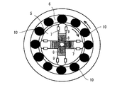
ここで、前記スウェージング加工を行う装置について説明する。スウェージング加工装置は図2に示すように、内側回転体5と外側回転体6とを備え、内側回転体5には90°離間して径方向に貫通穴7が形成され、各貫通穴7内には内側から順にスウェージング金型8とストライカー9が摺動自在に嵌合している。一方、外側回転体6には周方向に等間隔で12本のピン10が回転自在に保持されている。
Here, the apparatus which performs the said swaging process is demonstrated. As shown in FIG. 2, the swaging apparatus includes an
以上のスウェージング加工装置において、内側回転体5を時計廻りに、外側回転体6を反時計廻りに回転せしめると、遠心力によって内側回転体5に保持されているスウェージング金型8とストライカー9は径方向外側に付勢されるが、外側には外側回転体6が回転しており、この外側回転体6にはピン10が保持されており、このピン10は外側回転体6よりもその一部が内側に突出しているので、ピン10がストライカー9の外端部を通過する度にストライカー9を径方向内方に押し込み、これに連動してスウェージング金型8も径方向内方に押し込まれ、4つのスウェージング金型8の中心にセットされた素材の表面を数千回/分の速度で叩きスウェージング加工を行う。
In the swaging apparatus described above, when the
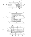
上記のスウェージング加工装置を用いて凹部2とアンダーカット部3を形成した素材1を成形するには、先ず図3(a)に示すように、クランパ11で素材1を把持するとともに、素材1の凹部2内にマンドレル12を挿入する。このマンドレル12の外径は目的とする製品(燃料噴射ノズル)の袋穴の内径と等しいものを用いる。
In order to form the
そして、図3(b)に示すように、マンドレル12で素材1をストッパ13に当接する位置まで押し込み、前記したようにスウェージング金型8によって素材1の外面を叩いてスウェージング加工を施す。このスウェージング加工により凹部2の内径はマンドレル12の外径まで縮径されるが、アンダーカット部3は残る。尚、素材の加工方法としては図示するような半径方向に工具を移動するプランジ加工に限らず、素材を軸方向に移動させるインフィード加工でもよい。
Then, as shown in FIG. 3B, the
この後、旋削加工を施して製品(燃料噴射ノズル)の外径形状とするのであるが、前記スウェージング金型8の先端形状を所定の形状にしておくことで、旋削加工を省略することができる。 After that, turning is performed to obtain the outer diameter shape of the product (fuel injection nozzle). However, turning the swaging die 8 to a predetermined shape may omit turning. it can.
(第2発明)
次に第2発明の実施例について説明する。第2発明は第1発明を更に改善したものであり、具体的には、第1発明にあっては、鍛造(前方押出し又は後方押出し)によって素材に大径の凹部を形成し、この凹部の内周にアンダーカット部を形成した後、当該凹部に目的とする部材の内周部の径と等しい径のマンドレルを挿入して外側からスウェージング加工し、その後、外面に研削加工などを施してノズル形状にするようにしている。
(Second invention)
Next, an embodiment of the second invention will be described. The second invention is a further improvement of the first invention. Specifically, in the first invention, a concave portion having a large diameter is formed in the material by forging (forward extrusion or backward extrusion). After forming an undercut part on the inner periphery, insert a mandrel with a diameter equal to the diameter of the inner peripheral part of the target member into the recess, swaging from the outside, and then grinding the outer surface. The nozzle shape is used.
第1発明の方法は、燃料噴射ノズルなどの成形には極めて有効であるが、スウェージング加工に用いる通常のマンドレルは先端部が平坦であるので、中空穴の雌テーパ状先端部の加工を後から行わなければならず、加工が面倒である。また後加工によって雌テーパ状先端部を形成しても当該雌テーパ状先端部の長さを正確に知ることができないので、最終的な外形寸法にする際の研削代を正確に知ることができず、このため先端の肉厚にばらつきが生じやすい。 Although the method of the first invention is extremely effective for forming a fuel injection nozzle or the like, the normal mandrel used for the swaging process has a flat tip, so that the processing of the female tapered tip of the hollow hole is later performed. It must be done from the beginning, processing is troublesome. In addition, even if the female tapered tip is formed by post-processing, the length of the female tapered tip cannot be accurately determined, so that the grinding allowance for final dimensions can be accurately determined. Therefore, the thickness of the tip tends to vary.
また、燃料噴射ノズルなどの成形には極めて細いマンドレルを用いる必要がある。極めて細いマンドレルを用いた場合に、図4に示すように、マンドレルの先端が凹部の中心からずれていると、ストッパに突き当てた際に素材が倒れ、大きな負荷がマンドレルにかかり座屈が生じることがある。また素材に倒れが生じると中空穴の深さ精度が得られないことにもなる。 In addition, it is necessary to use an extremely thin mandrel for molding the fuel injection nozzle and the like. When an extremely thin mandrel is used, as shown in FIG. 4, if the tip of the mandrel is displaced from the center of the recess, the material falls when it hits the stopper, and a large load is applied to the mandrel to cause buckling. Sometimes. In addition, if the material falls down, the depth accuracy of the hollow hole cannot be obtained.
そこで第2発明では、先ず、ビレットを切断して図5(a)に示す棒状素材21を用意する。この棒状素材としてはSCM415等が適当である。この後、図5(b)に示すように、冷間鍛造(前方押出し又は後方押出し)にて前記棒状素材21に凹部22を形成する。この凹部22は後に製品の内周部になる部分であるが、その径は製品の内周部よりも大きく、十分に機械加工が可能な大きさ(10mm以上)とする。
Therefore, in the second invention, first, the billet is cut to prepare the rod-shaped
棒状素材21を冷間鍛造したならば、図5(c)に示すように、凹部22にアンダーカット部23を形成し、続いて冷間でのスウェージング加工によって、図5(d)に示すように、前記凹部22を内径2〜4mmの袋穴24に成形し、更に旋削加工にて外周面を加工して図5(e)に示す製品(燃料噴射ノズル)を得る。
If the rod-shaped
尚、素材の加工方法としては図示するような半径方向に工具を移動するプランジ加工に限らず、素材を軸方向に移動させるインフィード加工でもよい。またスウェージング金型の先端形状を所定の形状にしておくことで、旋削加工を省略することもできる。 The material processing method is not limited to the plunge processing in which the tool is moved in the radial direction as shown in the drawing, but may be infeed processing in which the material is moved in the axial direction. In addition, turning the swaging die to a predetermined shape can eliminate the turning process.
前記スウェージング加工装置は第1発明に用いた装置と同様である。即ち図2に示すように、内側回転体5と外側回転体6とを備え、内側回転体5には90°離間して径方向に貫通穴7が形成され、各貫通穴7内には内側から順にスウェージング金型8とストライカー9が摺動自在に嵌合している。一方、外側回転体6には周方向に等間隔で12本のピン10が回転自在に保持されている。
The swaging apparatus is the same as that used in the first invention. That is, as shown in FIG. 2, the inner
以上のスウェージング加工装置において、内側回転体5を時計廻りに、外側回転体6を反時計廻りに回転せしめると、遠心力によって内側回転体5に保持されているスウェージング金型8とストライカー9は径方向外側に付勢されるが、外側には外側回転体6が回転しており、この外側回転体6にはピン10が保持されており、このピン10は外側回転体6よりもその一部が内側に突出しているので、ピン10がストライカー9の外端部を通過する度にストライカー9を径方向内方に押し込み、これに連動してスウェージング金型8も径方向内方に押し込まれ、4つのスウェージング金型8の中心にセットされた素材の表面を数千回/分の速度で叩きスウェージング加工を行う。
In the swaging apparatus described above, when the
上記のスウェージング加工装置を用いて凹部22とアンダーカット部23を形成した素材21を成形するには、先ず図6(a)に示すように、クランパ11で素材21を把持するとともに、素材21の凹部22内にマンドレル12を挿入する。このマンドレル12の外径は目的とする製品(燃料噴射ノズル)の袋穴24の内径と等しく、またマンドレル12の先端部12aは目的とする製品の袋穴24の先端の雌テーパ状部24aを形成するために円錐状をなしている。
In order to form the
そして、図6(b)に示すように、マンドレル12で素材21をストッパ13に当接する位置まで押し込み、前記したようにスウェージング金型8によって素材21の外面を叩いてスウェージング加工を施す。このスウェージング加工により凹部22の内径はマンドレル12の外径まで縮径されるが、アンダーカット部23は残る。この縮径に伴って素材21の底部の材料も矢印で示すように内側に移動し、マンドレルの先端部12aを包むように移動し、図6(c)に示すように、雌テーパ状部24aが形成される。
6 (b), the
上記の雌テーパ状部24aの位置はマンドレルの先端部12aと一致する。またマンドレル12の長さ及び素材21の端部の位置はセンサなどにより測定することができる。したがって、素材27の底部の厚さ(t0)を正確に知ることができ、この厚さ(t0)から研削代(t1)を決めることができる。即ち、マンドレルの先端部12aを長手方向の加工代として用いることができる。
The position of the female tapered
図7(a)は前記素材21の凹部22の中心に位置決め穴25を形成した例を示す図であり、この位置決め穴25にマンドレルの先端部12aを差し込むことで、スウェージング加工の際にマンドレル12がずれて、倒れが生じることがない。
FIG. 7A is a view showing an example in which a
前記位置決め穴25については、図7(b)に示すように、開き角がマンドレルの先端部12aの角度よりも小さいと、スウェージング加工後に欠肉となるおそれがあるので、位置決め穴25の深さはマンドレル先端部の長さと等しいかそれよりも浅く、また位置決め穴25の開き角度はマンドレル先端部の角度と等しいかそれよりも大きくする。
As for the
また、前記位置決め穴25の形成は、図8に示すように鍛造(前方押出し)によって凹部22を成形する際に同時に成形することが工程上有利である。また前方押出しの代わりに後方押出しによって凹部22と位置決め穴25を同時に成形してもよい。
Further, the
図9(a)及び(b)は鍛造の際に、凹部22の底部から所定の範囲において、前記位置決め穴25の他に、素材21の外周部または凹部22の内周部に余肉部21a、21bを設けた例を示している。スウェージング加工の際に、素材21の材料は軸方向に沿って開口方向に移動するため凹部22の底部付近では材料が不足するが、余肉部21a、21bを設けることでその不足分を補うことができる。
9 (a) and 9 (b) show that, in the forging, in the predetermined range from the bottom of the
(第3発明)
次に第3発明の実施例について説明する。第3発明は第1発明を更に改善したものであり、具体的には、第1発明にあっては、前記したように鍛造(前方押出し又は後方押出し)によって素材に大径の凹部を形成し、図10(a)に示すように、この凹部の内周にアンダーカット部を形成した後、当該凹部に目的とする部材の内周部の径と等しい径のマンドレルを挿入して外側からスウェージング加工し、その後、外面に研削加工などを施してノズル形状にするようにしている。
(Third invention)
Next, an embodiment of the third invention will be described. The third invention is a further improvement of the first invention. Specifically, in the first invention, as described above, a large-diameter recess is formed in the material by forging (forward extrusion or backward extrusion). As shown in FIG. 10 (a), after an undercut portion is formed on the inner periphery of the recess, a mandrel having a diameter equal to the diameter of the inner periphery of the target member is inserted into the recess to Zing is performed, and then the outer surface is ground to form a nozzle shape.
第1発明の方法は、燃料噴射ノズルなどの成形には極めて有効であるが、成形比を大きくすると、スウェージング加工の際に素材が長手方向に沿って開口方向に流動し、その際、図10(b)に示すように、凹部のコーナ部が取り残され、最終的には図10(c)に示すように、欠肉が発生することがある。 The method of the first invention is extremely effective for molding a fuel injection nozzle or the like. However, if the molding ratio is increased, the material flows in the opening direction along the longitudinal direction during swaging. As shown in FIG. 10 (b), the corner portion of the concave portion is left behind, and eventually, as shown in FIG.
そこで、第3発明では先ず、ビレットを切断して図11(a)に示す棒状素材31を用意する。この棒状素材としてはSCM415等が適当である。この後、図11(b)に示すように、冷間鍛造(前方押出し又は後方押出し)にて前記棒状素材31に凹部32を形成する。この凹部32は後に製品の内周部になる部分であるが、その径は製品の内周部よりも大きく、十分に機械加工が可能な大きさ(10mm以上)とする。
Therefore, in the third invention, first, a billet is cut to prepare a rod-shaped
前記凹部32の底部のコーナ部には面取り部32aが形成されている。図12(a)に示すように、面取り部32aはR面取りとされ、その形成領域はスウェージング加工用のマンドレルと凹部32の内周面との間のクリアランスとなる領域とする。そして、このクリアランス領域の全てを面取り部としてもよいが、35%以上の割合であれば欠肉を起こすことがない。
A chamfered
また、面取り部32aとしてはR面取りに限らず、図12(b)に示すようにC面取りとしてもよい。更にこの図に示すように、凹部32の中心にマンドレルの円錐状先端部を差し込む位置決め穴34を形成しておくことでスウェージング加工の際にマンドレルがずれて、倒れが生じることがない。
Further, the chamfered
尚、凹部32、面取り部32a及び位置決め穴34については、図13に示す冷間による鍛造成形(前方押出し)によって同時に成形することが加工効率上有利である。鍛造成形としては後方押出しでもよいが、パンチが座屈しやすいので前方押出しの方が有利である。
The
図11に戻って、棒状素材31を冷間鍛造したならば、図11(c)に示すように、凹部32にアンダーカット部33を形成し、続いて冷間でのスウェージング加工によって、図11(d)に示すように、前記凹部32を内径2〜4mmの袋穴34に成形し、更に旋削加工にて外周面を加工して図11(e)に示す製品(燃料噴射ノズル)を得る。
Returning to FIG. 11, if the bar-shaped
前記スウェージング加工装置は第1発明に用いた装置と同様である。即ち図2に示すように、内側回転体5と外側回転体6とを備え、内側回転体5には90°離間して径方向に貫通穴7が形成され、各貫通穴7内には内側から順にスウェージング金型8とストライカー9が摺動自在に嵌合している。一方、外側回転体6には周方向に等間隔で12本のピン10が回転自在に保持されている。
The swaging apparatus is the same as that used in the first invention. That is, as shown in FIG. 2, the inner
以上のスウェージング加工装置において、内側回転体5を時計廻りに、外側回転体6を反時計廻りに回転せしめると、遠心力によって内側回転体5に保持されているスウェージング金型8とストライカー9は径方向外側に付勢されるが、外側には外側回転体6が回転しており、この外側回転体6にはピン10が保持されており、このピン10は外側回転体6よりもその一部が内側に突出しているので、ピン10がストライカー9の外端部を通過する度にストライカー9を径方向内方に押し込み、これに連動してスウェージング金型8も径方向内方に押し込まれ、4つのスウェージング金型8の中心にセットされた素材の表面を数千回/分の速度で叩きスウェージング加工を行う。
In the swaging apparatus described above, when the
上記のスウェージング加工装置を用いて凹部32とアンダーカット部33を形成した素材31を成形するには、先ず図14(a)に示すように、クランパ11で素材31を把持するとともに、素材31の凹部32内にマンドレル12を挿入する。このマンドレル12の外径は目的とする製品(燃料噴射ノズル)の袋穴34の内径と等しく、またマンドレル12の先端部12aは目的とする製品の袋穴34の先端の雌テーパ状部34aを形成するために円錐状をなしている。
In order to form the
そして、図14(b)に示すように、マンドレル12で素材31をストッパ13に当接する位置まで押し込み、前記したようにスウェージング金型8によって素材31の外面を叩いてスウェージング加工を施す。このスウェージング加工により凹部32の内径はマンドレル12の外径まで縮径されるが、アンダーカット部33は残る。
14B, the
上記の縮径に伴って素材31の底部のコーナ部の材料も矢印で示すように内側に移動し、マンドレルの先端部12aを包むように移動し、図14(c)に示すように、雌テーパ状部34aが形成される。このとき、コーナ部は面取り部32aとなっているので、素材が移動する際に材料不足を生じることがない。
As the diameter decreases, the material of the corner portion at the bottom of the material 31 also moves inwardly as indicated by the arrow, moves so as to wrap the
尚、素材の加工方法としては図示するような半径方向に工具を移動するプランジ加工に限らず、素材を軸方向に移動させるインフィード加工でもよい。またスウェージング金型の先端形状を所定の形状にしておくことで、旋削加工を省略することもできる。 The material processing method is not limited to the plunge processing in which the tool is moved in the radial direction as shown in the drawing, but may be infeed processing in which the material is moved in the axial direction. In addition, turning the swaging die to a predetermined shape can eliminate the turning process.
(第4発明)
次に第4発明の実施例について説明する。第4発明は第1発明を更に改善したものであり、具体的には、第1発明にあっては、鍛造(前方押出し又は後方押出し)によって素材に大径の凹部を形成し、この凹部の内周にアンダーカット部を形成した後、当該凹部に目的とする部材の内周部の径と等しい径のマンドレルを挿入して外側からスウェージング加工し、その後、外面に研削加工などを施してノズル形状にするようにしている。
(Fourth invention)
Next, an embodiment of the fourth invention will be described. The fourth invention is a further improvement of the first invention. Specifically, in the first invention, a large-diameter recess is formed in the material by forging (forward extrusion or backward extrusion). After forming an undercut part on the inner periphery, insert a mandrel with a diameter equal to the diameter of the inner peripheral part of the target member into the recess, swaging from the outside, and then grinding the outer surface. The nozzle shape is used.
第1発明の方法は、燃料噴射ノズルなどの成形には極めて有効であるが、成形比を大きくすると、スウェージング加工の際に素材が長手方向に沿って開口方向に流動し、その結果、一部の製品には、図15に示すように、凹部の底部内周に欠肉が発生することがある。 The method of the first invention is extremely effective for molding a fuel injection nozzle or the like. However, if the molding ratio is increased, the material flows in the opening direction along the longitudinal direction during swaging, and as a result, In some products, as shown in FIG. 15, a lack of thickness may occur on the inner periphery of the bottom of the recess.
そこで第4発明では、ビレットを切断して図16(a)に示す棒状素材41を用意する。この棒状素材としてはSCM415等が適当である。この後、図16(b)に示すように、冷間鍛造(前方押出し又は後方押出し)にて前記棒状素材41に凹部42を形成する。この凹部42は後に製品の内周部になる部分であるが、その径は製品の内周部よりも大きく、十分に機械加工が可能な大きさ(10mm以上)とする。
Therefore, in the fourth invention, the billet is cut to prepare the rod-shaped
前記冷間鍛造として図17に示すように前方押出しを行う場合には、凹部42の底部から所定長範囲の棒状素材41の外周に余肉部41aを設ける。この余肉部41aは後述するスウェージング加工の際の材料流れを補うものであり、好ましい範囲(L)としては、スウェージング加工の際のマンドレル径(ノズル内径)を(d)とした場合、2d≦L≦4dである。
When forward extrusion is performed as the cold forging as shown in FIG. 17, a
また冷間鍛造として図18に示すように後方押出しを行う場合には、凹部42の内周面であって底部から所定長範囲に余肉部41bを設ける。この余肉部41bについても好ましい範囲は2d≦L≦4dである。
余肉の発生は底部から、マンドレルと下孔とのクリアランス分の位置から発生するため、少なくともマンドレル径(d)の2倍の余肉部が無いと、発生位置より上方で材料不足が生じるおそれがあり、また、4倍を超えると、アンダーカット部へ材料の流入が起こり、アンダーカット部の形状が変形してしまうおそれがある。そこで、範囲をdの2〜4倍とした。また余肉部の体積は、事前にテストして、発生した欠肉部の体積以上であればよい。
尚、実施例では冷間鍛造と同時に余肉部を成形する例を示したが、凹部42の成形とは別に余肉部を成形してもよい。
Further, when performing backward extrusion as cold forging as shown in FIG. 18, a
Since the surplus is generated from the bottom, from the position corresponding to the clearance between the mandrel and the pilot hole, if there is no surplus that is at least twice the mandrel diameter (d), there is a risk of material shortage above the generation position. In addition, if it exceeds four times, inflow of material into the undercut portion may occur, and the shape of the undercut portion may be deformed. Therefore, the range is set to 2 to 4 times d. Moreover, the volume of the surplus part should just be more than the volume of the lacking part which tested beforehand and produced | generated.
In the embodiment, the surplus portion is formed simultaneously with the cold forging. However, the surplus portion may be formed separately from the formation of the
上記の如くして、棒状素材1を冷間鍛造したならば、図16(c)に示すように、凹部42にアンダーカット部43を形成し、続いて冷間でのスウェージング加工によって、図16(d)に示すように、前記凹部42を内径2〜4mmの袋穴44に成形し、更に旋削加工にて外周面を加工して図15(e)に示す製品(燃料噴射ノズル)を得る。
If the rod-shaped
前記スウェージング加工装置は第1発明に用いた装置と同様である。即ち図2に示すように、内側回転体5と外側回転体6とを備え、内側回転体5には90°離間して径方向に貫通穴7が形成され、各貫通穴7内には内側から順にスウェージング金型8とストライカー9が摺動自在に嵌合している。一方、外側回転体6には周方向に等間隔で12本のピン10が回転自在に保持されている。
The swaging apparatus is the same as that used in the first invention. That is, as shown in FIG. 2, the inner
以上のスウェージング加工装置において、内側回転体5を時計廻りに、外側回転体6を反時計廻りに回転せしめると、遠心力によって内側回転体5に保持されているスウェージング金型8とストライカー9は径方向外側に付勢されるが、外側には外側回転体6が回転しており、この外側回転体6にはピン10が保持されており、このピン10は外側回転体6よりもその一部が内側に突出しているので、ピン10がストライカー9の外端部を通過する度にストライカー9を径方向内方に押し込み、これに連動してスウェージング金型8も方向内方に押し込まれ、4つのスウェージング金型8の中心にセットされた素材の表面を数千回/分の速度で叩きスウェージング加工を行う。
In the swaging apparatus described above, when the
上記のスウェージング加工装置を用いて凹部42とアンダーカット部43を形成した素材41を成形するには、先ず図19(a)に示すように、クランパ11で素材41を把持するとともに、素材41の凹部42内にマンドレル12を挿入する。このマンドレル12の外径は目的とする製品(燃料噴射ノズル)の袋穴の内径と等しいものを用いる。
In order to form the
そして、図19(b)に示すように、マンドレル12で素材41をストッパ13に当接する位置まで押し込み、前記したようにスウェージング金型8によって素材41の外面を叩いてスウェージング加工を施す。このスウェージング加工により凹部42の内径はマンドレル12の外径まで縮径されるが、アンダーカット部43は残る。このとき、素材41の材料は軸方向に沿って開口方向に移動するため凹部42の底部付近では材料が不足するが、その不足分は余肉部41aまたは41bから補われる。
Then, as shown in FIG. 19B, the
尚、素材の加工方法としては図示するような半径方向に工具を移動するプランジ加工に限らず、素材を軸方向に移動させるインフィード加工でもよい。 The material processing method is not limited to the plunge processing in which the tool is moved in the radial direction as shown in the drawing, but may be infeed processing in which the material is moved in the axial direction.
この後、旋削加工を施して製品(燃料噴射ノズル)の外径形状とするのであるが、前記スウェージング金型8の先端形状を所定の形状にしておくことで、旋削加工を省略することができる。 After that, turning is performed to obtain the outer diameter shape of the product (fuel injection nozzle). However, turning the swaging die 8 to a predetermined shape may omit turning. it can.
Claims (12)
1:部材の内周部よりも大径の凹部を素材に形成する工程。
2:前記凹部の内周にアンダーカット部を形成する工程。
3:前記アンダーカット部が形成された素材の凹部に目的とする部材の内周部の径と等しい径のマンドレルを挿入する工程。
4:前記マンドレルを挿入した素材の外側からスウェージング加工して前記アンダーカット部を残した状態で素材の前記凹部の内径をマンドレル外径まで縮小する工程。 A molding method for providing an undercut portion on an inner peripheral portion of a member, comprising the following steps 1 to 4.
1: A step of forming a concave portion having a diameter larger than that of the inner peripheral portion of the member in the material.
2: The process of forming an undercut part in the inner periphery of the said recessed part.
3: A step of inserting a mandrel having a diameter equal to the diameter of the inner peripheral portion of the target member into the concave portion of the material in which the undercut portion is formed.
4: A step of reducing the inner diameter of the concave portion of the material to the outer diameter of the mandrel while swaging from the outside of the material into which the mandrel is inserted, leaving the undercut portion.
Priority Applications (1)
| Application Number | Priority Date | Filing Date | Title |
|---|---|---|---|
| JP2010023774A JP4823367B2 (en) | 2003-12-22 | 2010-02-05 | Method for forming member having undercut portion |
Applications Claiming Priority (13)
| Application Number | Priority Date | Filing Date | Title |
|---|---|---|---|
| JP2003424945 | 2003-12-22 | ||
| JP2003424945 | 2003-12-22 | ||
| JP2004047664 | 2004-02-24 | ||
| JP2004047664 | 2004-02-24 | ||
| JP2004050293 | 2004-02-25 | ||
| JP2004050293 | 2004-02-25 | ||
| JP2004050240 | 2004-02-25 | ||
| JP2004050270 | 2004-02-25 | ||
| JP2004050240 | 2004-02-25 | ||
| JP2004050270 | 2004-02-25 | ||
| JP2004237872 | 2004-08-18 | ||
| JP2004237872 | 2004-08-18 | ||
| JP2010023774A JP4823367B2 (en) | 2003-12-22 | 2010-02-05 | Method for forming member having undercut portion |
Related Parent Applications (1)
| Application Number | Title | Priority Date | Filing Date |
|---|---|---|---|
| JP2005516423A Division JP4566132B2 (en) | 2003-12-22 | 2004-10-21 | Method for forming cylindrical member |
Publications (2)
| Publication Number | Publication Date |
|---|---|
| JP2010142877A JP2010142877A (en) | 2010-07-01 |
| JP4823367B2 true JP4823367B2 (en) | 2011-11-24 |
Family
ID=34714679
Family Applications (3)
| Application Number | Title | Priority Date | Filing Date |
|---|---|---|---|
| JP2005516423A Expired - Fee Related JP4566132B2 (en) | 2003-12-22 | 2004-10-21 | Method for forming cylindrical member |
| JP2010023801A Expired - Fee Related JP4951683B2 (en) | 2003-12-22 | 2010-02-05 | Molding method of valve guide |
| JP2010023774A Expired - Fee Related JP4823367B2 (en) | 2003-12-22 | 2010-02-05 | Method for forming member having undercut portion |
Family Applications Before (2)
| Application Number | Title | Priority Date | Filing Date |
|---|---|---|---|
| JP2005516423A Expired - Fee Related JP4566132B2 (en) | 2003-12-22 | 2004-10-21 | Method for forming cylindrical member |
| JP2010023801A Expired - Fee Related JP4951683B2 (en) | 2003-12-22 | 2010-02-05 | Molding method of valve guide |
Country Status (5)
| Country | Link |
|---|---|
| US (1) | US8151436B2 (en) |
| JP (3) | JP4566132B2 (en) |
| DE (1) | DE112004002531T5 (en) |
| GB (1) | GB2424848B (en) |
| WO (1) | WO2005061151A1 (en) |
Families Citing this family (9)
| Publication number | Priority date | Publication date | Assignee | Title |
|---|---|---|---|---|
| DE102010026984A1 (en) * | 2010-07-13 | 2012-01-19 | Continental Automotive Gmbh | Method and device for producing a recess in an injector body of an injection valve |
| CN102139287B (en) * | 2010-11-19 | 2013-03-06 | 无锡曙光模具有限公司 | Stamping die for necking of pipe body |
| JP5625220B2 (en) * | 2013-01-15 | 2014-11-19 | 株式会社飯塚製作所 | Forging method and forging apparatus |
| CN104139143B (en) * | 2014-08-11 | 2016-02-24 | 贵州航天新力铸锻有限责任公司 | Elliposoidal Shell Forging Parts forging method |
| CN104139145A (en) * | 2014-08-11 | 2014-11-12 | 贵州航天新力铸锻有限责任公司 | Method for forging guide horn mouth forge pieces applied to internal components of nuclear reactor |
| US9611824B2 (en) * | 2015-02-18 | 2017-04-04 | Caterpillar Inc. | Process for manufacturing an injector body |
| EP3433483A1 (en) * | 2016-05-11 | 2019-01-30 | Peter Fuchs Technology Group Ag | High-pressure line |
| CN106374183B (en) * | 2016-09-23 | 2021-07-06 | 浙江申吉钛业股份有限公司 | Flanged bending waveguide tube based on positive cold extrusion method and preparation device and method thereof |
| DE102017114509A1 (en) * | 2017-06-29 | 2019-01-03 | Federal-Mogul Valvetrain Gmbh | Cavity valve with optimized internal shaft geometry and method for its production |
Family Cites Families (39)
| Publication number | Priority date | Publication date | Assignee | Title |
|---|---|---|---|---|
| US336507A (en) * | 1886-02-16 | Ore-separator | ||
| GB694472A (en) * | 1950-07-28 | 1953-07-22 | Gen Motors Corp | Improved machine for swaging metal tubes |
| GB923995A (en) * | 1961-03-13 | |||
| US3581728A (en) * | 1970-02-18 | 1971-06-01 | Caterpillar Tractor Co | Grooved valve stem guide |
| AT322329B (en) * | 1973-12-04 | 1975-05-12 | Gfm Fertigungstechnik | FORGING MACHINES FOR PRODUCING IN PARTICULAR SCRAP BARRELS |
| JPS5433238B2 (en) * | 1974-01-23 | 1979-10-19 | ||
| JPS5659552A (en) | 1979-10-18 | 1981-05-23 | Komatsu Ltd | Production of parts having undercut |
| JPS5697716A (en) * | 1980-01-08 | 1981-08-06 | Chiyoda Seiki:Kk | Gas cutting tip and method of producing same |
| JPS5797834A (en) * | 1980-12-08 | 1982-06-17 | Toshiba Corp | Manufacture of nozzle body |
| JPS5834214B2 (en) * | 1981-07-10 | 1983-07-25 | 芳一 阪村 | Method for manufacturing parts with large diameter holes at both ends |
| JPS58181910A (en) | 1982-04-16 | 1983-10-24 | Ishikawajima Harima Heavy Ind Co Ltd | Overflow type gate |
| JPS58181910U (en) * | 1982-05-31 | 1983-12-05 | トヨタ自動車株式会社 | Cylinder head for internal combustion engine |
| US4435972A (en) * | 1982-06-28 | 1984-03-13 | Simon Joseph A | Process for forming integral spindle-axle tubes |
| JPS6068130A (en) * | 1983-09-24 | 1985-04-18 | Mitsubishi Heavy Ind Ltd | Method and device for forming cylindrical object |
| JPS61197707A (en) * | 1985-02-25 | 1986-09-02 | Mitsubishi Heavy Ind Ltd | Intake and exhaust valve for internal-combustion engine |
| JPS6263105A (en) * | 1985-09-13 | 1987-03-19 | Toyota Motor Corp | Valve lifter for direct type tappet valve system |
| JPH03207545A (en) | 1990-01-10 | 1991-09-10 | Nissan Motor Co Ltd | Manufacture of cupped product |
| JPH03253708A (en) * | 1990-03-05 | 1991-11-12 | Sumitomo Electric Ind Ltd | Valve guide for internal combustion engine |
| JPH04167944A (en) * | 1990-10-31 | 1992-06-16 | Japan Steel Works Ltd:The | Swage autofrettage method for thick cylindrical body |
| US5280675A (en) | 1992-07-13 | 1994-01-25 | The Torrington Company | Camshaft and method of making a camshaft |
| US5337476A (en) * | 1992-07-13 | 1994-08-16 | The Torrington Company | Method of making a camshaft |
| JP3368600B2 (en) | 1992-10-30 | 2003-01-20 | 住友電気工業株式会社 | Manufacturing method of high heat resistant aluminum alloy |
| JP3164254B2 (en) * | 1992-12-28 | 2001-05-08 | 愛知製鋼株式会社 | Manufacturing method of hollow shaft forgings |
| JP3617693B2 (en) * | 1994-07-21 | 2005-02-09 | 株式会社デンソー | Method of manufacturing fuel injection device component having undercut |
| US5522246A (en) * | 1995-04-19 | 1996-06-04 | U.S. Manufacturing Corporation | Process for forming light-weight tublar axles |
| JPH0921730A (en) * | 1995-07-07 | 1997-01-21 | Olympus Optical Co Ltd | Dispensation nozzle cleaner for medical analyzer |
| GB9623469D0 (en) * | 1996-11-12 | 1997-01-08 | Lucas Ind Plc | Injector |
| JPH10296378A (en) * | 1997-04-30 | 1998-11-10 | Nippon Steel Corp | Production of extremely thick-wall electric resistance welded tube with push-in forging |
| JP3221850B2 (en) * | 1997-10-01 | 2001-10-22 | 中島銅工株式会社 | Heating chip and method of manufacturing the same |
| JPH11350059A (en) | 1998-06-05 | 1999-12-21 | Nippon Piston Ring Co Ltd | Valve guide |
| JP2000008132A (en) * | 1998-06-23 | 2000-01-11 | Nippon Piston Ring Co Ltd | Valve guide made of high silicon aluminum alloy for internal combustion engine |
| DE10105368A1 (en) * | 2001-02-06 | 2002-08-29 | Siemens Ag | Fuel injection nozzle for an internal combustion engine |
| US6457343B1 (en) * | 2001-03-06 | 2002-10-01 | Larry Shed | Tubing swaging machine |
| JP4354133B2 (en) * | 2001-08-10 | 2009-10-28 | カヤバ工業株式会社 | Cylinder processing method |
| JP3995526B2 (en) * | 2002-05-20 | 2007-10-24 | 臼井国際産業株式会社 | High pressure fuel injection pipe with connecting head |
| JP2006070827A (en) * | 2004-09-02 | 2006-03-16 | Usui Kokusai Sangyo Kaisha Ltd | High-pressure fuel injection pipe and molding method therefor |
| JP2006170192A (en) * | 2004-11-17 | 2006-06-29 | Denso Corp | Fuel injection nozzle and its manufacturing method |
| DE102004056147B3 (en) * | 2004-11-20 | 2006-08-03 | Gkn Driveline International Gmbh | Reduction of tubes over a stepped mandrel for producing hollow shafts with undercut in one operation |
| JP5435190B2 (en) * | 2007-03-30 | 2014-03-05 | 日立オートモティブシステムズ株式会社 | Tube processing method and cylinder device manufacturing method |
-
2004
- 2004-10-21 DE DE112004002531T patent/DE112004002531T5/en not_active Withdrawn
- 2004-10-21 WO PCT/JP2004/015623 patent/WO2005061151A1/en active Application Filing
- 2004-10-21 GB GB0613554A patent/GB2424848B/en not_active Expired - Fee Related
- 2004-10-21 US US10/583,939 patent/US8151436B2/en not_active Expired - Fee Related
- 2004-10-21 JP JP2005516423A patent/JP4566132B2/en not_active Expired - Fee Related
-
2010
- 2010-02-05 JP JP2010023801A patent/JP4951683B2/en not_active Expired - Fee Related
- 2010-02-05 JP JP2010023774A patent/JP4823367B2/en not_active Expired - Fee Related
Also Published As
| Publication number | Publication date |
|---|---|
| US20080034573A1 (en) | 2008-02-14 |
| JP4951683B2 (en) | 2012-06-13 |
| JP2010110824A (en) | 2010-05-20 |
| DE112004002531T5 (en) | 2006-11-02 |
| JP4566132B2 (en) | 2010-10-20 |
| JPWO2005061151A1 (en) | 2007-07-12 |
| GB0613554D0 (en) | 2006-08-30 |
| JP2010142877A (en) | 2010-07-01 |
| GB2424848A (en) | 2006-10-11 |
| GB2424848B (en) | 2007-12-12 |
| US8151436B2 (en) | 2012-04-10 |
| WO2005061151A1 (en) | 2005-07-07 |
Similar Documents
| Publication | Publication Date | Title |
|---|---|---|
| JP4823367B2 (en) | Method for forming member having undercut portion | |
| US9016184B2 (en) | Precision forged cartridge case | |
| JP6212349B2 (en) | Spark plug metal shell manufacturing method, spark plug metal shell manufacturing method, and spark plug manufacturing method | |
| JP2003285138A (en) | Method for manufacturing cam piece for built-up cam shaft | |
| US20100299925A1 (en) | Method for forming a gear | |
| WO2006137198A1 (en) | Method for producing outer ring member of constant velocity universal joint | |
| EP2121221B1 (en) | Method of making a powder metal forging | |
| JP2005059097A (en) | Forging method, forged article and forging equipment | |
| CN111230037A (en) | Production process of flange for improving utilization rate of raw materials | |
| JP2006266286A (en) | Manufacturing method for outer ring member for constant velocity joint and its intermediate molded body | |
| CN101545440B (en) | Method for manufacturing swivel of actuating lever for motorcycle | |
| CN110153363A (en) | A kind of manufacturing process for turning to the cold and hot forging of guide rod and combining | |
| US7588834B2 (en) | Trimless forged products and method | |
| US8806912B2 (en) | Powder metal forging and method and apparatus of manufacture | |
| CN111014554A (en) | Forging process and forging die for deep hole shaft head | |
| JP6612600B2 (en) | Manufacturing method by cold forging of cylindrical metal fittings with polygonal flanges | |
| JPH0890135A (en) | Joint metal tool and manufacture of this half-made product | |
| JP2008111469A (en) | Method of manufacturing constant velocity joint outer ring member | |
| CN101176905B (en) | Method of forming member, valve guide and method of forming the same and method of forming tubular member | |
| US7104109B2 (en) | Double-cavity heading die | |
| RU2254199C1 (en) | Method for making self-locking nuts blanks with nylon ring and flange | |
| JPS63264237A (en) | Production of raw material for hollow valve | |
| EP2566655B1 (en) | Piston assembly multiple step forming process | |
| RU2107574C1 (en) | Process for manufacturing semi-tubular rivets | |
| JPH07275992A (en) | Manufacture of main tool for spark plug |
Legal Events
| Date | Code | Title | Description |
|---|---|---|---|
| TRDD | Decision of grant or rejection written | ||
| A977 | Report on retrieval |
Free format text: JAPANESE INTERMEDIATE CODE: A971007 Effective date: 20110811 |
|
| A01 | Written decision to grant a patent or to grant a registration (utility model) |
Free format text: JAPANESE INTERMEDIATE CODE: A01 Effective date: 20110816 |
|
| A01 | Written decision to grant a patent or to grant a registration (utility model) |
Free format text: JAPANESE INTERMEDIATE CODE: A01 |
|
| A61 | First payment of annual fees (during grant procedure) |
Free format text: JAPANESE INTERMEDIATE CODE: A61 Effective date: 20110906 |
|
| R150 | Certificate of patent or registration of utility model |
Free format text: JAPANESE INTERMEDIATE CODE: R150 |
|
| FPAY | Renewal fee payment (event date is renewal date of database) |
Free format text: PAYMENT UNTIL: 20140916 Year of fee payment: 3 |
|
| LAPS | Cancellation because of no payment of annual fees |