JP4792123B1 - Underwater working machine and underwater working method - Google Patents
Underwater working machine and underwater working method Download PDFInfo
- Publication number
- JP4792123B1 JP4792123B1 JP2010219363A JP2010219363A JP4792123B1 JP 4792123 B1 JP4792123 B1 JP 4792123B1 JP 2010219363 A JP2010219363 A JP 2010219363A JP 2010219363 A JP2010219363 A JP 2010219363A JP 4792123 B1 JP4792123 B1 JP 4792123B1
- Authority
- JP
- Japan
- Prior art keywords
- shaft
- work
- underwater
- water
- main body
- Prior art date
- Legal status (The legal status is an assumption and is not a legal conclusion. Google has not performed a legal analysis and makes no representation as to the accuracy of the status listed.)
- Active
Links
Images


Landscapes
- Earth Drilling (AREA)
Abstract
【課題】水中地盤の状況に関わらず安定した状態で作業を行うことを可能とした、水中作業機と水中作業方法を提案する。
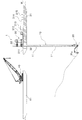
【解決手段】先端が水底WBに到達するように作業船31により保持されたシャフト10と、シャフト10を昇降するとともにシャフト10の軸心を中心に旋回可能に構成された作業機本体20とを備える水中作業機1と、これを利用する水中作業方法。水中作業方法は、シャフト10を水上WLから水底WBにまで立設させる立設工程と、シャフト10に沿って下降させることによりシャフト10の下端部に作業機本体20を配置する配置工程と、作業機本体20により水底WBを掘削する掘削工程を備えている。
【選択図】図1An underwater work machine and an underwater work method that enable a work to be performed in a stable state regardless of the state of the underwater ground.
A tip shaft 10 which is held by work boats 31 to reach the bottom of the water W B, the working machine body 20 arranged to be rotatable about the axial center of the shaft 10 as well as lifting the shaft 10 An underwater work machine 1 comprising: an underwater work method using the same. Underwater work method, a standing step of standing the shaft 10 from the water W L to the sea bed W B, the arrangement step of arranging a work machine body 20 to the lower end of the shaft 10 by lowering along the shaft 10 , and a drilling step of drilling the seabed W B by machine body 20.
[Selection] Figure 1
Description
本発明は、水中作業機および水中作業方法に関する。 The present invention relates to an underwater work machine and an underwater work method.
海や湖等の水底を掘削する場合には、作業船に設置されたグラブバケットを昇降させることにより行うのが一般的である。 When excavating the bottom of a sea or lake, it is common to raise and lower a grab bucket installed on a work boat.
ところが、グラブバケットによる掘削は、浚渫等の軟弱地盤の掘削に適しているものの岩盤等の掘削には不向きであり、掘削が可能な地盤が限られていた。
また、水上からの操作により水底の掘削を行うため、水底の状況に応じた掘削を行うことができない場合があった。
However, although excavation with a grab bucket is suitable for excavation of soft ground such as dredging, it is not suitable for excavation of rock or the like, and the ground that can be excavated is limited.
In addition, since the bottom of the water is excavated from the surface of the water, there are cases where excavation according to the state of the bottom of the water cannot be performed.
そのため、特許文献1には、水底の状況に応じて効率的な掘削を行うことを目的として、水底で自走する水中掘削機械により水底掘削を行うとともに、水中掘削機械により掘削された土砂等を吸い上げる揚泥用配管により水底掘削方法が開示されている。
Therefore, in
また、特許文献2には、水底に立設された支柱の下端部に旋回可能に固定された水中作業機により、水底の捨石の均し作業を行う工法が開示されている。
Further,
特許文献1に記載の水中掘削機械は、水底を走行するものであるため、比較的平らな水底では作業することができるものの、急傾斜地等では作業することができなかった。
Since the underwater excavation machine described in
また、特許文献2に記載の水中作業機は、支柱の下端部に固定されているため、移動が困難であった。つまり、下端部に水中作業機が設置された状態で支柱の移動や位置決めを行うため、水の抵抗や水流の影響を受けやすく、支柱の移動や位置決めに手間を要していた。
Moreover, since the underwater working machine of
そのため、本発明は、簡易に移動することができ、また、水中地盤の状況に関わらず安定した状態で作業を行うことを可能とした、水中作業機と水中作業方法を提案することを課題とする。 Therefore, it is an object of the present invention to propose an underwater work machine and an underwater work method that can be easily moved and that can work in a stable state regardless of the state of the underwater ground. To do.
前記課題を解決するために、第一発明の水中作業機は、下端面が水底に当接した状態で作業船に保持されるシャフトと、前記シャフトの下端部において当該シャフトを中心に旋回可能に配設された作業機本体と、を備える水中作業機であって、前記作業機本体は、前記シャフトを昇降することを特徴としている。
前記シャフトは、例えば、水上の作業船に設置されたシャフト固定装置により保持される。
In order to solve the above-described problem, the underwater work machine according to the first aspect of the present invention is capable of turning around a shaft held by a work boat with a lower end surface in contact with a water bottom, and a lower end portion of the shaft. An underwater work machine including a work machine main body arranged, wherein the work machine main body moves up and down the shaft.
The shaft is held by, for example, a shaft fixing device installed on a work boat on the water.
また、第二発明に係る水中作業機は、下端部が水底に固定されるとともに水面から突出した上端部が固定されたシャフトと、前記シャフトの下端部において当該シャフトを中心に旋回可能に配設された作業機本体と、を備える水中作業機であって、前記作業機本体は、前記シャフトを昇降することを特徴としている。
前記シャフトは、例えば、作業構台に設置されたシャフト固定装置により保持される。
Moreover, underwater working machine according to the second invention, a shaft upper end portion is fixed projecting from the water surface together with the lower end portion is fixed to the sea bed, pivotably disposed around the shaft at the lower end of the shaft An underwater work machine, wherein the work machine body moves up and down the shaft.
The shaft is held by, for example, a shaft fixing device installed on a work gantry.
かかる水中作業機によれば、シャフトの位置決めを行ってから、シャフトの下端部に作業機本体を配設することができるため、水中作業機の移動を簡易に行うことが可能である。そのため、広範囲での作業を簡易に行うことができる。
また、作業機本体は、下端が水底に当接し、上端部が水面上において支えられたシャフトにより支持されているため、水底地盤の状況に関わらず作業機本体を配設することが可能である。
According to such an underwater work machine, since the work machine main body can be disposed at the lower end portion of the shaft after the shaft is positioned, the underwater work machine can be easily moved. Therefore, a wide range of work can be easily performed.
Further, since the work implement main body is supported by a shaft whose lower end is in contact with the water bottom and whose upper end is supported on the water surface, it is possible to dispose the work implement main body regardless of the situation of the water bottom ground. .
本発明の水中作業機の作業機本体は、前記シャフトを上下動する昇降筒部と、前記昇降筒部を中心に回動する旋回部と、前記旋回部に設置された作業アームと、を備えるものであってもよい。 The working machine main body of the underwater work machine of the present invention includes an elevating cylinder part that moves the shaft up and down, a turning part that rotates around the elevating cylinder part, and a work arm that is installed in the turning part. It may be a thing.
かかる水中作業機によれば、作業アームのアタッチメント(バケット、サンドポンプ、インパクトブレーカ等)を交換するのみで、多種多様な水中作業を行うことができる。 According to such an underwater work machine, a wide variety of underwater work can be performed only by exchanging attachments (buckets, sand pumps, impact breakers, etc.) of work arms.
また、前記シャフトの外面に、当該シャフトの軸に沿ってラックが形成されており、前記昇降筒部は、前記ラックを走行する昇降手段を備えていれば、昇降筒部を滑落することなく安全に昇降させることができる。 In addition, if a rack is formed on the outer surface of the shaft along the axis of the shaft, and the elevating cylinder part includes elevating means for running on the rack, the elevating cylinder part is safe without sliding down. Can be moved up and down.
また、前記シャフトの外面に当該シャフトの軸に沿ってガイドレールが形成されており、前記昇降筒部が前記ガイドレールを走行するガイドローラを備えていれば、昇降筒部が昇降時に横方向(シャフトの周方向)にぶれることがなく、安全に作業を行うことができる。 In addition, if a guide rail is formed on the outer surface of the shaft along the axis of the shaft, and the elevating cylinder part includes a guide roller that travels on the guide rail, the elevating cylinder part is laterally moved ( The work can be done safely without shaking in the circumferential direction of the shaft.
前記昇降筒部に、当該昇降筒部の外周面に形成されたスプロケットと、両端が前記昇降筒部に固定されているとともに前記スプロケットに噛合するチェーンとを具備させ、前記旋回部に、前記チェーンと噛合するチェーンギヤと、前記チェーンギヤに回転力を付与する旋回用モータとを具備させてもよい。このようにすると、前記旋回用モータの回転力により前記チェーンギヤが前記チェーンに沿って走行することで当該旋回部が旋回するようになる。 The elevating cylinder portion includes a sprocket formed on an outer peripheral surface of the elevating cylinder portion, and a chain having both ends fixed to the elevating cylinder portion and meshing with the sprocket, and the swivel portion includes the chain And a chain motor for applying a rotational force to the chain gear. If it does in this way, the said rotation part comes to turn because the said chain gear drive | works along the said chain with the rotational force of the said motor for rotation.
また、前記シャフトが、軸方向に連結された複数のシャフト構成材を有していれば、水深に応じてシャフトの長さを変化させることが可能となる。 Further, if the shaft has a plurality of shaft constituent members connected in the axial direction, the length of the shaft can be changed according to the water depth.
また、前記シャフトにモニタリング手段が設置されていれば、シャフトや作業機本体の位置確認や水底の状況確認を簡易に行うことができる。 Moreover, if the monitoring means is installed in the shaft, it is possible to easily check the position of the shaft and the working machine main body and the status of the water bottom.
また、本発明の水中作業方法は、シャフトを水底に立設する立設工程と、前記シャフトの上端部に配置した作業機本体を前記シャフトに沿って下降させることにより、前記シャフトの下端部に作業機本体を配置する配置工程と、前記作業機本体に取り付けられた作業アームを介して水底における作業を行う作業工程と、を備える水中作業方法であって、前記立設工程では、前記シャフトの下端部を水底に固定するとともに、水面から突出した当該シャフトの上端部を水面上において固定し、前記作業工程では、前記シャフトの軸心を中心に前記作業機本体を旋回させることにより向きを変え、前記シャフトの周囲に対する作業を行うことを特徴としている。 Further, the underwater work method of the present invention includes a standing step of standing the shaft on the bottom of the water, and lowering the work implement body disposed on the upper end portion of the shaft along the shaft, thereby lowering the lower end portion of the shaft. An underwater operation method comprising an arrangement step of disposing a work implement main body and a work step of performing work on a water bottom via a work arm attached to the work implement main body, wherein in the standing step , The lower end is fixed to the water bottom, and the upper end of the shaft protruding from the water surface is fixed on the water surface. In the work process, the work implement main body is turned around the shaft center to change the direction. The operation is performed around the shaft.
かかる水中作業方法によれば、水中地盤の状況に関わらず、作業機本体を所望の位置に配置して、掘削作業を行うことができる。 According to such an underwater work method, it is possible to perform excavation work by placing the work implement main body at a desired position regardless of the state of the underwater ground.
前記立設工程では、複数本のシャフト構成材を連結することにより水底から水面上に至る長さのシャフトを形成すればよい。 In the standing step, a shaft having a length extending from the water bottom to the water surface may be formed by connecting a plurality of shaft constituent members.
本発明の水中作業機および水中作業方法によれば、簡易に移動することができ、また、水中地盤の状況に関わらず安定した状態で作業を行うことを可能となる。 According to the underwater work machine and the underwater work method of the present invention, it is possible to move easily, and it is possible to work in a stable state regardless of the state of the underwater ground.
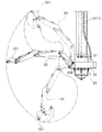
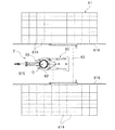
第1の実施の形態に係る水中作業機1は、図1に示すように、シャフト10と、作業機本体20と、シャフト固定装置30と、を備えている。
本実施形態では、水中作業機1により水底WBの掘削作業を行う場合について説明する。
As shown in FIG. 1, the
In the present embodiment describes the case where the
シャフト10は、水底WBから水面WL上に至る長さを有しており、下端部を水底WBに食い込ました(当接させた)状態で、水面WLから突出している。シャフト10の上端部は、水上の作業船31に設置されたシャフト固定装置30により保持されている。
シャフト10は、軸方向に連結された複数のシャフト構成材11,11,…により、所定の長さを備えて構成されている。シャフト構成材11は、筒状の部材からなり、上下のシャフト構成材11と治具(図示省略)を介して連結されている。
なお、シャフト構成材11同士の連結方法は限定されるものではなく、適宜行えばよい。また、シャフト10を構成するシャフト構成材11の本数は限定されるものではなく、水深に応じて適宜設定すればよい。また、水深が浅い場合には、シャフト10を1本のシャフト構成材11により構成してもよい。
The
In addition, the connection method of the shaft
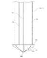
図2に示すように、シャフト10の外面には、シャフト10の軸に沿ってラック12とガイドレール13が形成されている。
As shown in FIG. 2, a
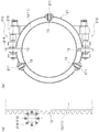
ラック12は、図3(a)に示すように、後記する作業機本体20の昇降手段210と噛合する複数の歯が形成された突条部材であって、シャフト10の軸方向に対して連続して形成されている。図3(b)に示すように、本実施形態では、二つのラック12,12がシャフト10の中心軸を挟んで対向するような位置に配置されている。
なお、ラック12は、昇降手段の構成に応じて適宜構成すればよく、必ずしも突条である必要はない。また、ラック12の数も限定されるものではなく、適宜形成すればよい。
As shown in FIG. 3A, the
Note that the
ガイドレール13は、後記する作業機本体20のガイドローラ211の走行が可能となるように形成された突条であって、図2に示すように、シャフト10の軸方向に対して連続して形成されている。
The
図3(b)に示すように、本実施形態ではシャフト10の断面に対して3本のガイドレール13,13,13を等間隔で配設している。なお、ガイドレール13の本数は限定されるものではない。また、ガイドレール13は溝状に形成されていてもよく、その形状はガイドローラ211の構成に応じて適宜設定すればよい。
As shown in FIG. 3B, in this embodiment, three
シャフト10の下端には、図2に示すように、設置台14が形成されている。
設置台14は、水底WBに食い込むことが可能となるように、先細りになっている。
As shown in FIG. 2, an installation table 14 is formed at the lower end of the
Installation table 14, so that it is possible to bite into the bottom of the water W B, are tapered.
設置台14は、ストッパー板141と、ストッパー板141の下面中心に立設された支持部材142と、支持部材142を中心に放射状に配設された複数枚の羽根板143,143,…と、を備えて構成されている。
The installation table 14 includes a
ストッパー板141は、シャフト10の外径よりも大きな直径(幅)を有する鋼板であって、シャフト構成材11の下端を遮蔽するように固定されている。
ストッパー板141は、その周縁がシャフト構成材11の外周面よりも突出しているため、図4に示すように、作業機本体20のシャフト10からの抜け落ちを防止するストッパーとして機能する。
The
The
支持部材142は、上端がストッパー板141の中心に固定されている。支持部材142は、その周囲に放射状に配置された羽根板143,143,…を支持している(図2参照)。
支持部材142は筒状の部材であってもよいし、密実な部材であってもよい。また、支持部材142は円柱であってもよいし、多角柱であってもよい。
The upper end of the
The
羽根板143は、図2に示すように、台形状(略三角形状)に形成された板材である。羽根板143の上端はストッパー板141の下面に接合されており、羽根板143の側端面は支持部材142に接合されている。
The
設置台14は、放射状に配設された羽根板143により、側面視で先端(下端)が縮径するように、略五角形を呈している。
なお、設置台14の構成は、限定されるものではなく適宜構成すればよい。
The
The configuration of the installation table 14 is not limited and may be appropriately configured.
設置台14の羽根板143を水底WBに食い込ませることにより、シャフト10の先端が固定される。
By bite into
作業機本体20は、シャフト10の下端部に配置されていて、シャフト10の軸心を中心に旋回することで、シャフト10の周囲の掘削を行う。
The
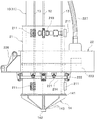
作業機本体20は、図5に示すように、シャフト10に装着される昇降筒部21と、昇降筒部21を中心にして回動する旋回部22と、旋回部22に取り付けられた作業アーム23と、を備えている。
As shown in FIG. 5, the
昇降筒部21は、図3(b)および図6(a)に示すように、シャフト10の外径よりも大きな内径を有した筒状の部材であって、シャフト10のラック12を走行する昇降手段210と、シャフト10のガイドレール13を走行するガイドローラ211と、スプロケット212と、チェーン213と、ローラーパス214と、を備えている。
As shown in FIGS. 3B and 6A, the elevating
昇降手段210は、昇降用モータ215と昇降用歯車216とを備えている。本実施形態では、一対のラック12に対応して、一対の昇降手段210が配設されている。
The lifting / lowering means 210 includes a lifting / lowering
昇降用モータ215は、昇降筒部21の外面に固定されていて、昇降用歯車216に回転力を付与する。
The elevating
昇降用歯車216は、昇降用モータ215の回転軸に固定されており、昇降用モータ215の動力により回転する。昇降用歯車216には、シャフト10のラック12と噛合する歯が形成されている(図3(a)参照)。
昇降筒部21には、昇降用歯車216の配置に応じて開口部が形成されている。昇降用歯車216は、この開口部を挿通してラック12に噛合している。
The elevating
An opening is formed in the
昇降用歯車216は、昇降用モータ215の動力により回転し、ラック12を走行する。昇降用歯車216がラック12を走行することで昇降筒部21がシャフト10に沿って昇降する。
The elevating
昇降用歯車216は、ラック12に噛合しているため、昇降筒部21の落下が防止されている。
なお、昇降手段210の構成は限定されるものではなく、適宜構成することが可能である。
Since the elevating
In addition, the structure of the raising / lowering means 210 is not limited, It can be comprised suitably.
ガイドローラ211は、昇降筒部21に回転可能に支持された車輪である。ガイドローラ211の周面には、突条であるガイドレール13が挿入可能な凹部が形成されている。
昇降筒部21には、ガイドローラ211の配置に応じて開口部が形成されている。ガイドローラ211は当該開口部を挿通してガイドレール13に当接している。
The
An opening is formed in the elevating
本実施形態では、図3(b)および図6(a)に示すように、一つのガイドレール13につき、上下二つのガイドローラ211,211(合計六つ)が配設されている。ガイドローラ211の数は限定されるものではない。
In this embodiment, as shown in FIG. 3B and FIG. 6A, two
ガイドローラ211は、凹部にガイドレール13を係合した状態で走行することで、昇降筒部21がシャフト10の周方向で回転することを防止している。これにより、昇降用歯車216が、ラック12から外れることがない。
The
スプロケット212は、図6(b)に示すように、昇降筒部21の外周面に固定されている。スプロケット212は、昇降筒部21の外面に形成されたチェーン固定部217の一端から他端に到達するように、昇降筒部21の外周面に周設されている。
なお、スプロケット212の配置は限定されるものではないが、本実施形態では、上下のガイドローラ211,211の間であって、昇降筒部21の高さ方向中間部に形成している。
As shown in FIG. 6B, the
In addition, although arrangement | positioning of the
チェーン213は、図7(a)に示すように、両端がチェーン固定部217に固定されているとともに、スプロケット212に噛合した状態で、スプロケット212に係合している。
なお、チェーン213は、スプロケット212の長さよりも大きな長さを有しており、後記する旋回部22の旋回用モータの配設が可能に構成されている。
As shown in FIG. 7A, both ends of the
The
ローラーパス214は、図6(a)に示すように、昇降筒部21の周方向に沿って形成された突条であって、後記する旋回部22の旋回ローラ221,222(図7(b)参照)が走行可能に構成されている。本実施形態のローラーパス214は、断面視矩形状に形成されており、上下面および側面上での旋回ローラ221,222による走行が可能に構成されている。
As shown in FIG. 6A, the
ローラーパス214の配置は限定されるものではないが、本実施形態では、下側のガイドローラ211,211,211とスプロケット212の間に形成する。
Although the arrangement of the
旋回部22には、図7(a)に示すように、昇降筒部21を挿通するための貫通孔220が形成されており、貫通孔220に昇降筒部21(シャフト10)が挿通されている。
As shown in FIG. 7A, the turning
旋回部22の下面には、図7(b)に示すように、ローラーパス214を走行する第一旋回ローラ221と第二旋回ローラ222(なお、本明細書において「第一旋回ローラ221」と「第二旋回ローラ222」とを区別しない場合は単に「旋回ローラ221,222」と称する)が配設されている。
On the lower surface of the
第一旋回ローラ221は、ローラーパス214の側面を走行する車輪を備えている。かかる車輪は、縦方向に配設された軸を中心に回転可能に配設されている。
旋回部22には、第一旋回ローラ221が等間隔で4つ配設されている。なお、第一旋回ローラ221の数は限定されるものではない。
The
In the
第二旋回ローラ222は、ローラーパス214の上面または下面を走行する上下2段の車輪を備えている。両車輪は横方向に配設された軸を中心に回転可能に配設されている。第二旋回ローラ222は、上下の車輪によりローラーパス214を挟持した状態で、当該ローラーパス214の表面を走行する。
旋回部22には、第二旋回ローラ222が等間隔で4つ配設されている。なお、第二旋回ローラ222の数は限定されるものではない。
The
In the
旋回部22は、旋回用モータ223を内部に備えている。
旋回用モータ223は、チェーンギヤ224に回転力を付与する。
The turning
The turning
チェーンギヤ224は、スプロケット212から離間したところに配置されており、図8(a)に示すように、チェーン213と噛合する歯を有している。
チェーンギヤ224は、旋回用モータ223が駆動することにより回転し、チェーン213に沿って走行する。チェーンギヤ224がチェーン213に沿って走行することで、旋回部22は、昇降筒部21の外周面に沿って旋回する(図8(b)参照)。
The
The
なお、チェーンギヤ224の昇降筒部21側近傍には、補助ギヤ225,225がチェーン213の外側に配設されており、チェーン213がスプロケット212から脱落することを防止している。
Note that auxiliary gears 225 and 225 are disposed outside the
旋回部22には、図4に示すように、貫通孔220を挟んで旋回用モータ223の反対側に、作業アーム23を取り付けるためのアーム取付部226が形成されている。
なお、符号227は、動力ケーブルや制御ケーブルが内挿された管路であって、水上の作業船31から延設されている。
As shown in FIG. 4, an
作業アーム23の先端には、図5に示すように、掘削用バケット231が回動可能に装着されており、作業アーム23の基端はアーム取付部226に回動可能に接続されている。
As shown in FIG. 5, the
シャフト固定装置30は、図1に示すように、作業船31に配設されたジャッキである。シャフト固定装置30は、上下2段のクランプ32、32を有している。
シャフト固定装置30は、上下のクランプ32,32によりシャフト10の上端部を把持することで、シャフト10を固定している。
As shown in FIG. 1, the
The
また、シャフト固定装置30が伸縮すると、上側のクランプ32が上下動する。上側のクランプ32によりシャフト10を把持した状態で、シャフト固定装置30を下降させると、シャフト10を下降させることが可能となる(図9参照)。
Further, when the
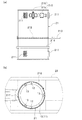
作業船31には、図9(a)に示すように、シャフト固定装置30の近傍に開口部311が形成されている。開口部311には、シャフト10が挿通されている。
また、作業船31には、作業機本体20やシャフト固定装置30を操作・駆動するための各種装置(例えば、動力ケーブルや制御ケーブルが巻きつけられたケーブルリール312や、操作室313、発電機314、油圧ユニット315等)が配設されている(図1参照)。
As shown in FIG. 9A, the
The
次に、本実施形態の水中作業機1を利用して水底WBの掘削を行う水中作業方法について説明する。
本実施形態の水中作業方法は、立設工程と、配置工程と、作業工程と、移動工程と、を備えている。
Next, a description will be given water working methods for performing drilling underwater W B using the underwater working
The underwater operation method of the present embodiment includes a standing process, an arrangement process, a work process, and a movement process.
立設工程は、所定の位置に配設された作業船31を利用して、シャフト10を水底WBに立設する工程である。
シャフト10は、複数本のシャフト構成材11,11,…を連結することにより水底WBから水面WL上に至る長さに形成する。
Standing step utilizes the
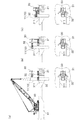
立設工程では、図9(a)に示すように、作業船31に隣接して配設されたクレーン船41のクレーン40によりシャフト構成材11を配置する。
まず、クレーン40によりシャフト構成材11を吊持し、シャフト固定装置30の近傍にシャフト構成材11を配置する。
In the erecting process, as shown in FIG. 9A, the
First, the
次に、図9(b)に示すように、シャフト固定装置30の上側のクランプ32によりシャフト構成材11を把持する。そして、図9(c)に示すように、上側のクランプ32を下降させることにより、シャフト10(シャフト構成材11)を下降させる。
なお、このとき、クランプ32を貫通してシャフト10に挿入される落下防止ピンを配設することで、シャフト構成材11がクランプ32から滑り落ちる(抜け落ちる)ことを防止する。シャフト10の落下防止方法は、ピンに限定されるものではない。
Next, as shown in FIG. 9B, the
At this time, by providing a fall prevention pin that passes through the
なお、シャフト構成材11同士の連結は、既設のシャフト構成材11(シャフト10)の上端部を下側のクランプ32により把持した状態で、クレーン40を介して新たなシャフト構成材11を上方に配設し、次いで、新たなシャフト構成材11を上側のクランプ32により保持し、シャフト構成材11同士を突き合わせた状態で連結すればよい。
The
そして、下側のクランプ32を解放した状態で上側のクランプ32を下降させることで、シャフト10を下降させる。
同様の作業を繰り返すことにより、水底WBに至る長さのシャフト10を形成する。
Then, the
By repeating the same operation, to form the
シャフト10は、水底WBに下端が当接した状態で、さらに下降させることで、設置台14を水底WBに食い込ませる。
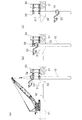
配置工程は、立設工程において立設されたシャフト10の上端部に配置した作業機本体20をシャフト10に沿って下降させることにより、シャフト10の下端部に作業機本体20を配置する工程である。
The arranging step is a step of arranging the work implement
作業機本体20は、まず、クレーン40によりシャフト10の上方に配置される。このとき、上側のクランプ32によるシャフト10の把持は解放し、作業機本体20の挿通が可能な状態とする。
The
次に、図10(a)に示すように、作業機本体20の昇降筒部21にシャフト10の上端を挿通し、作業機本体20をシャフト10の上端部に配置する。このとき、昇降用歯車216をラック12に噛合させておく。
Next, as shown in FIG. 10A, the upper end of the
作業機本体20を下降させて、上下のクランプ32,32の間に配置したら、図10(b)に示すように、上側のクランプ32によりシャフト10の上端部を把持し、その後、下側のクランプ32を開放する。
When the
下側のクランプ32を開放したら、図10(c)に示すように、昇降装置210を駆動させて、作業機本体20をシャフト10に沿って下降させる。作業機本体20が、下側のクランプ32よりも下側に位置したならば、下側のクランプ32でシャフト10を把持する。
When the
作業工程は、シャフト10の下端に配設された作業機本体20により、水底WBでの掘削を行う工程である。
水底WBの掘削は、作業機本体20に取り付けられた作業アーム23を介して行う。
Working process, the working
Drilling underwater W B is performed through the working
作業工程では、シャフト10の軸心を中心に作業機本体20を旋回させることにより作業機本体20の向きを変え、作業機本体20が掘削すべき領域に正体したならば、掘削作業を実施する。このように、作業機本体20の旋回、掘削作業を適宜繰り返し、シャフト10の周囲を掘削する。
In the work process, the work machine
移動工程は、作業工程終了後に、水中作業機を移動させる工程である。 A movement process is a process of moving an underwater work machine after completion | finish of a work process.
移動工程では、まず、作業機本体20をシャフト10に沿って上昇させ、配置工程と逆の手順により作業機本体20を回収する。
次に、シャフト10を水底WBに当接しない高さまで上昇させる。このとき、必要に応じて所定数のシャフト構成材11を取り外す。
そして、シャフト10をシャフト固定装置30により把持した状態で、作業船31を所定の位置に配置する。
In the moving process, first, the
Next, it is raised to a height which does not contact the
Then, with the
作業船31を所定の位置に配置したら、立設工程、配置工程および作業工程を再度実施する。
なお、作業船31を移動させたら、掘削作業が完了した箇所においてグラブバケットなどによりズリ回収を行ってもよい。
When the
In addition, if the
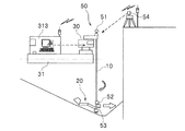
本実施形態の水中作業機1は、図11に示すように、モニタリング手段50を備えており、作業機本体20の遠隔操作が可能に構成されている。
As shown in FIG. 11, the
モニタリング手段50は、シャフト10の上端部に設置されたミラー51と、シャフト10の下端部に設置された傾斜計52と、作業機本体20の作業アーム23の作業方向に照射可能に設置されたマルチビーム測深機53と、作業アーム23の作業方向を撮影する水中カメラ(図示省略)と、シャフト10から離れた位置(図11では地上)に据えつけられたトータルステーション54と、を備えている。
The
ミラー51は、トータルステーション54から照射される光波を反射するものである。ミラー51は、シャフト10の位置確認を行うことが可能となるように、トータルステーション54から視認できる位置に配置されている。
The
傾斜計52は、シャフト10の傾斜角度を計測する。傾斜計52の設置箇所は、シャフト10の傾斜を測定することができれば、シャフト10の下端部に限定されるものではない。
The
マルチビーム測深機53は、作業アーム23の作業方向を計測することで、作業アーム23による掘削を行う水底WBの形状を音波により測定する。水底WBの形状の確認後、掘削作業を開始する。
水中カメラは、水底WBの状況を撮影するものである。作業員は、作業船31等の操作室において、水底WBの状況を確認しながら水中作業機1の操作を行うことができる。
Underwater camera is to shoot the status of the bottom of the water W B. Workers in the operation chamber
以上、本実施形態の水中作業機1および水中作業方法によれば、シャフト10により作業機本体20が支持されているため、急傾斜等であっても、作業機本体20を配設し、掘削作業を実施することができる。
As described above, according to the
シャフト10は、先端の設置台が水底WBに差し込まれるとともに、上端部がシャフト固定装置30により保持されているため安定している。そのため、シャフト10の下端部に配設された作業機本体20による掘削作業を精度よく行うことができる。
また、モニタリング手段50により、所望の位置に水中作業機1を配設することができ、高品質施工が可能である。
また、マルチビーム測深機53により掘削に先立ち水底WBの状況を把握するため、計画に応じた掘削作業を行うことができる。
Moreover, the underwater working
Further, in order to grasp the situation of underwater W B prior to drilling by multibeam sounder 53 can perform drilling operations in accordance with the plan.
モニタリング手段50を介して水底WBの状況を確認した上で作業を行うため、既設構造物に近接して作業を行う場合であっても、既設構造物に損傷を与えることなく作業を行うことができる。
モニタリング手段50は、掘削予定の地形情報、測深結果、作業時の管理測量のデータにより、掘削必要深さまたは削岩必要深さおよび掘削バケット231等の先端位置の情報をモニターに表示する。そのため、作業員は、モニターにより水底WBの状況を確認しながら水中作業機1の遠隔操作を行うことができる。
For working after confirming the status of the water bottom W B via the monitoring means 50, even when working in close proximity to the existing structures, to perform the work without damaging the existing structures Can do.
The monitoring means 50 displays information on the necessary excavation depth or the required rock drilling depth and the tip position of the
シャフト10は、複数のシャフト構成材11を連結することにより構成されているため、水深に応じた長さに適宜変更することができる。
Since the
作業機本体20の配置は、作業船31上から立設されたシャフト10に沿って下降させるため、安全に配置することができる。
また、作業機本体20は、シャフト10に形成されたラック12に噛合させた昇降手段210により行うため、安全に配置される。また、ガイドレール13により昇降筒部21の周方向でのズレが防止されているため、昇降手段210がラック12から外れることが防止されていて、安全性が確保されている。
Since the work machine
Further, the work machine
旋回部22は、ローラーパス214を走行する旋回ローラ221,222により、昇降筒部21に対してずれることなく旋回することができ、安全性が確保されている。
旋回部22の旋回は、スプロケット212に配設されたチェーン213に沿ってチェーンギヤ224を駆動させることで安全に行うことができる。補助ギヤ225,225により、チェーン213がスプロケット212とチェーンギヤ224から外れることが防止されており、安全性に優れている。
The turning
The turning of the turning
掘削作業機1は、簡易に構成されているため、メンテナンスに要する手間や費用を削減することができる。
Since the
移動工程において、作業船31の移動を、シャフト10を下方に延設させたまま行うことで、シャフト10の回収に要する手間を省略することができる。
作業機本体20を回収した状態で移動するため、大きな水の抵抗を受けることなく移動することができる。
In the moving process, the
Since the work machine
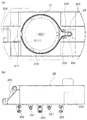
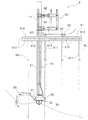
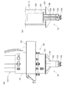
第2の実施の形態に係る水中作業機2は、図12に示すように、シャフト10と、作業機本体20と、シャフト固定装置60と、を備えている。
As shown in FIG. 12, the
シャフト10は、水底WBから水面WL上に至る長さを有しており、下端部を水底WBに食い込ました(当接させた)状態で、水面WLから突出している。シャフト10の上端部は、水面上の作業構台61に設置されたシャフト固定装置60により保持されている。
この他のシャフト10の構成は、第1の実施の形態で示した内容と同様なため、詳細な説明は省略する。
また、作業機本体20の構成も、第1の実施の形態で示した内容と同様なため、詳細な説明は省略する。
Since the configuration of the
Moreover, since the structure of the working machine
シャフト固定装置60は、図12〜図14に示すように、作業構台61に配設されたジャッキであって、移動架台63を介して移動可能に配設されている。
As shown in FIGS. 12 to 14, the
作業構台61は水面上に形成された人工地盤であって、図12および図13に示すように、水底WBの地盤から立設された支持杭611と、複数の支持杭611の上端に横架された桁受桁612と、桁受桁612の上面の架設された覆工受桁613と、覆工受桁613の上面に敷設された覆工板614と、により構成されている。
なお、作業構台61の構成は限定されるものではない。例えば、運河の川岸、堤防、岸壁等の既設の構造物や地盤を作業構台として使用してもよい。
Working
The configuration of the
作業構台61には、図13および図14に示すように、シャフト10の立設が可能となるように、開口部615が形成されている。また、作業構台61の上面には、開口部615に沿って一対(二条)のレール616,616が敷設されている。二条のレール616,616は、開口部615を挟んで両側に敷設されている。
なお、開口部615は必要に応じて形成すればよい。
As shown in FIGS. 13 and 14, the
Note that the
作業構台61には、作業機本体20やシャフト固定装置60等を操作・駆動するための各種装置(例えば、動力ケーブルや制御ケーブルが巻きつけられたケーブルリールや、操作室、発電機、油圧ユニット等)が配設されている。さらに、作業構台61の移動架台63の近傍に図示しないクレーンが配置されている。
The
移動架台63は、開口部615を跨って配設されており、一対のレール616,616上を走行する複数の車輪631,631を備えている。
なお、移動架台63は、必ずしも開口部615に跨って配設されている必要はない。例えば、作業構台61から張り出した状態で配設してもよい。
The
Note that the
シャフト固定装置60は、移動架台63の上面に固定されており、移動架台63を介して所定の位置に移動する。
なお、本実施形態では、移動架台63がレール616,616に沿って前後方向に移動可能に構成されている場合について説明したが、移動架台63は横方向(左右)に移動してもよく、移動架台63の移動方向は限定されるものではない。また、移動架台63の移動手段は、レール上を走行する場合に限定されるものではなく、例えばジャッキ式やタイヤ式であってもよい。
The
In the present embodiment, the case where the
シャフト固定装置60は、必ずしも作業構台61に対して移動する移動架台63に固定されている必要はなく、例えば固定式の架台に固定されていてもよい。また、シャフト固定装置60は、作業構台61に直接固定されていてもよい。
この他のシャフト固定装置60の構成は、第1の実施の形態で示したシャフト固定装置30と同様なため、詳細な説明は省略する。
The
Since the structure of the other
次に、本実施形態の水中作業機2を利用して水底WBの掘削を行う水中作業方法について説明する。
本実施形態の水中作業方法は、立設工程と、配置工程と、作業工程と、移動工程と、を備えている。
Next, a description will be given water working methods for performing drilling underwater W B using the underwater working
The underwater operation method of the present embodiment includes a standing process, an arrangement process, a work process, and a movement process.
立設工程は、所定の位置に配置されたシャフト固定装置60によりシャフト10を水底WBに立設する工程である。
シャフト固定装置60の配置は、移動架台63を移動させることにより行う。
Standing step is a step of erecting the
The
立設工程では、移動架台63の近傍であって、作業構台61上に配設されたクレーン(図示せず)と、シャフト固定装置60とを利用して、複数本のシャフト構成材11,11,…を連結することにより水底WBから水面WL上に至る長さシャフト10を形成する。
In the erection process, a plurality of
この他の立設工程における作業内容は、第1の実施の形態で示した内容と同様なため、詳細な説明は省略する。
また、配置工程および作業工程における作業内容は、第1の実施の形態で示した内容と同様なため、詳細な説明は省略する。
なお、水中作業機2は、第1の実施の形態の水中作業機1と同様に、モニタリング手段50を備えており、作業機本体20の遠隔操作が可能に構成されている。
Since the work contents in the other standing process are the same as the contents shown in the first embodiment, the detailed description is omitted.
Further, since the work contents in the arrangement process and the work process are the same as the contents shown in the first embodiment, detailed description thereof is omitted.
The
移動工程では、まず、作業機本体20をシャフト10に沿って上昇させ、配置工程と逆の手順により作業機本体20を回収する。
次に、シャフト10を水底WBに当接しない高さまで上昇させる。このとき、必要に応じて所定数のシャフト構成材11を取り外す。
そして、シャフト10をシャフト固定装置60により把持した状態で、移動架台63を移動させる。
In the moving process, first, the
Next, it is raised to a height which does not contact the
Then, the moving
移動架台63を所定の位置に配置したら、立設工程、配置工程および作業工程を再度実施する。
なお、移動架台63を移動させたら、掘削作業が完了した箇所においてグラブバケットなどによりズリ回収を行ってもよい。
When the
In addition, after moving the
以上、本実施形態の水中作業機2および水中作業方法によれば、例えば運河、堤防、岸壁等から水中作業を行うことが可能となる。そのため、作業船を配置する手間を省略することが可能となる。
As described above, according to the
移動工程において、移動架台63の移動を、シャフト10を下方に延設させたまま行うことで、シャフト10の回収に要する手間を省略することができる。
作業機本体20を回収した状態で移動するため、大きな水の抵抗を受けることなく移動することができる。
In the moving process, the movement of the moving
Since the work machine
この他の第2の実施の形態に係る水中作業機2および水中作業方法による効果は、第1の実施の形態で示した内容と同様なため、詳細な説明は省略する。
Since the effects of the
以上、本発明について、好適な実施形態について説明した。しかし、本発明は、前述の各実施形態に限られず、前記の各構成要素については、本発明の趣旨を逸脱しない範囲で、適宜変更が可能である。 The preferred embodiments of the present invention have been described above. However, the present invention is not limited to the above-described embodiments, and the above-described constituent elements can be appropriately changed without departing from the spirit of the present invention.
例えば、本発明の水中作業機の使用箇所は限定されるものではなく、例えば海、湖、池や貯水池、河川等に使用することができる。また、作業船についても自航式、曳航式台船、組立台船等様々な作業船を使用することができる。また、作業構台の構成も限定されるものではなく、適宜構成することが可能である。 For example, the use location of the underwater work machine of this invention is not limited, For example, it can be used for the sea, a lake, a pond, a reservoir, a river, etc. In addition, various work vessels such as self-propelled, towed carrier and assembly carrier can be used as the work vessel. Further, the configuration of the work gantry is not limited, and can be appropriately configured.
また、前記各実施形態では、本発明の水中作業機を利用して水底WBの掘削を行う場合について説明したが、本発明の水中作業機の用途は、掘削バケットによる掘削に限定されるものではなく、あらゆる水中作業に使用することができる。
例えば、作業アーム23に設置されたアタッチメントを、インパクトブレーカ232(図15(a)参照)や油圧式切削機に代えることで、水底WBの岩盤や水中構造物の破砕作業を行ってもよい。また、アタッチメントして水中ポンプ233(図15(b)参照)を設置すれば、浚渫工に使用することができる。また、アタッチメントとしてブラシを設置すれば、水底WBの清掃にも使用することができる。
The ones, in the respective embodiments, the case has been described where the using underwater working machine of the present invention performs the drilling of underwater W B, use of the water working machine of the present invention, which is limited to the drilling by the drilling bucket Rather, it can be used for any underwater work.
For example, the installation has been attachment to the working
前記実施形態では、移動工程においてシャフト10を水中に延設したままで作業船31または移動架台63を移動させたが、作業船31または移動架台63の移動は、シャフト10を回収してから行ってもよい。このようにすれば、作業船31または移動架台63の移動時の抵抗を少なくすることで、作業船31または移動架台63の配置を簡易に行うことができる。
In the above-described embodiment, the
第1の実施の形態では、クレーン40を別の作業船(クレーン船41)に配置したが、例えば、シャフト固定装置30が配設された作業船31にクレーン40を配置してもよく、クレーン40の設置箇所は限定されるものではない。
また、クレーン40はクローラクレーンに限定されるものではない。
In the first embodiment, the
The
シャフト10を保持する装置として、作業船31または移動架台63に設置されたシャフト固定装置30を採用するものとしたが、シャフト10の保持する装置はこれに限定されるものではない。例えば、図15(c)に示すように、作業船31(作業構台61)上にアームにクランプ32が設置された支援バックホウ301を配設し、当該支援バックホウによりシャフト10の上端部を保持してもよい。
As a device for holding the
前記各実施形態では、シャフト10の下端に設置された設置台14によりシャフト10の下端を水底に食い込ませるものとしたが、シャフト10の下端の形状は限定されるものではなく、適宜形成することが可能である。
例えば、設置台14の構成は前記実施形態で示したものに限定されるものではなく、適宜形成すればよいし、また、設置台14は省略してもよい。
In each of the above embodiments, the lower end of the
For example, the configuration of the installation table 14 is not limited to that shown in the above embodiment, and may be formed as appropriate, and the installation table 14 may be omitted.
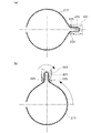
また、図16(a)に示すように、シャフト10の先端に、オーガー付設置台15を設置してもよい。
オーガー付設置台15は、ストッパー板151と、ケーシング152と、ケーシングヘッド153と、オーガーヘッド154と、複数枚の羽根板158,158,…と、を備えて構成されている。
In addition, as shown in FIG. 16A, an auger-equipped installation table 15 may be installed at the tip of the
The auger-equipped mounting table 15 includes a
ケーシング152は、図16(b)に示すように、上端がストッパー板151の中心部を貫通してシャフト10の内部に配設されていて、下端は下側(水底側)に突出している。また、ケーシング152の下端には、複数のカッタービットを先端に有するケーシングヘッド153が固定されている。なお、ケーシング152の突出長は限定されるものではなく、適宜設定すればよい。
As shown in FIG. 16B, the
ケーシング152の内部には、シャフト10の内部に配設された駆動ユニット156の回転軸155が配設されている。なお、駆動ユニット156は、ストッパー板151に固定された架台を介してシャフト10の内部に配設されている。駆動ユニット156の設置箇所や設置方法は限定されるものではない。
A
回転軸155の先端には、水底WBを掘削するためのオーガーヘッド154が固定されている。
オーガーヘッド154は、ケーシング152(ケーシングヘッド153)の先端から突出するように配置されている。
The tip of the
The
オーガー付設置台15は、駆動ユニット156を駆動させることにより回転軸155を介してオーガーヘッド154を回転させて水底WBを掘削し、シャフト10の先端を挿入する(食い込ませる)ための穴を形成する。また、ケーシングヘッド153を備えているため、水底WBに接触することでケーシング152が変形することを防止している。
Installation table 15 with auger drilling underwater W B to rotate the
また、シャフト10は、図17に示すように、下端が開口していてもよい。このとき、シャフト10の下端に複数の歯16,16,…を形成し、この歯16,16,…を水底WBに食い込ませることで、シャフト10を水底WBに据え付けることができる。
また、図示は省略するが、下端が開口したシャフト10の内部に掘削機を配置してもよい。このようにすれば、シャフト10の下端の開口部からこの掘削機のオーガーヘッドにより水底WBを掘削し、シャフト10挿入用の穴を形成することでシャフト10を水底WBに据え付けることができる。
Moreover, as shown in FIG. 17, the
Although not shown, the excavator may be disposed inside the
モニタリング手段50の構成は、前記実施形態で示したものに限定されるものではなく、適宜構成すればよい。
The configuration of the
1,2 水中作業機
10 シャフト
11 シャフト構成材
12 ラック
13 ガイドレール
20 作業機本体
21 昇降筒部
210 昇降手段
211 ガイドローラ
212 スプロケット
213 チェーン
22 旋回部
223 旋回用モータ
224 チェーンギヤ
23 作業アーム
30 シャフト固定装置
31 作業船
50 モニタリング手段
60 シャフト固定装置
61 作業構台
DESCRIPTION OF
Claims (12)
前記シャフトの下端部において当該シャフトを中心に旋回可能に配設された作業機本体と、を備える水中作業機であって、
前記作業機本体は、前記シャフトを昇降することを特徴とする、水中作業機。 A shaft held by the work boat with the lower end surface in contact with the water bottom;
An underwater work machine comprising: a work machine main body disposed so as to be pivotable about the shaft at a lower end portion of the shaft;
The work implement body moves up and down the shaft, and is an underwater work implement.
前記シャフトの下端部において当該シャフトを中心に旋回可能に配設された作業機本体と、を備える水中作業機であって、
前記作業機本体は、前記シャフトを昇降することを特徴とする、水中作業機。 A shaft upper end portion is fixed projecting from the water surface together with the lower end portion is fixed to the sea bed,
An underwater work machine comprising: a work machine main body disposed so as to be pivotable about the shaft at a lower end portion of the shaft;
The work implement body moves up and down the shaft, and is an underwater work implement.
前記昇降筒部を中心にして回動する旋回部と、
前記旋回部に取り付けられた作業アームと、を備えることを特徴とする、請求項1乃至請求項4のいずれか1項に記載の水中作業機。 The working machine main body includes an elevating cylinder part attached to the shaft;
A revolving part that rotates about the elevating cylinder part;
The underwater work machine according to any one of claims 1 to 4, further comprising a work arm attached to the swivel unit.
前記昇降筒部は、前記ラックを走行する昇降手段を備えていることを特徴とする、請求項5に記載の水中作業機。 A rack is formed on the outer surface of the shaft along the axis of the shaft,
The underwater working machine according to claim 5, wherein the elevating cylinder part includes elevating means for traveling the rack.
前記昇降筒部は、前記ガイドレールを走行するガイドローラを備えていることを特徴とする、請求項5または請求項6に記載の水中作業機。 On the outer surface of the shaft, a guide rail is formed along the axis of the shaft,
The underwater working machine according to claim 5 or 6, wherein the elevating cylinder part includes a guide roller that travels on the guide rail.
前記旋回部は、前記チェーンと噛合するチェーンギヤと、前記チェーンギヤに回転力を付与する旋回用モータと、を備えていて、
前記旋回用モータの回転力により前記チェーンギヤが前記チェーンに沿って走行することで当該旋回部が旋回することを特徴とする、請求項5乃至請求項7のいずれか1項に記載の水中作業機。 The elevating cylinder part includes a sprocket formed on the outer peripheral surface of the elevating cylinder part, and a chain having both ends fixed to the elevating cylinder part and meshing with the sprocket.
The turning unit includes a chain gear that meshes with the chain, and a turning motor that applies a rotational force to the chain gear,
The underwater work according to any one of claims 5 to 7, wherein the turning portion turns by the chain gear traveling along the chain by the rotational force of the turning motor. Machine.
前記シャフトの上端部に配置した作業機本体を前記シャフトに沿って下降させることにより、前記シャフトの下端部に前記作業機本体を配置する配置工程と、
前記作業機本体に取り付けられた作業アームを介して水底における作業を行う作業工程と、を備える水中作業方法であって、
前記立設工程では、前記シャフトの下端部を水底に固定するとともに、水面から突出した当該シャフトの上端部を水面上において固定し、
前記作業工程では、前記シャフトの軸心を中心に前記作業機本体を旋回させることにより向きをかえ、前記シャフトの周囲に対する作業を行うことを特徴とする、水中作業方法。 A standing process of standing the shaft on the bottom of the water;
Arranging the work implement main body at the lower end of the shaft by lowering the work implement main body arranged at the upper end of the shaft along the shaft;
An underwater work method comprising: a work process for performing work at the bottom of the water via a work arm attached to the work machine body,
In the erecting step, the lower end of the shaft is fixed to the water bottom, and the upper end of the shaft protruding from the water surface is fixed on the water surface,
In the work process, the work implement main body is turned around the shaft center to change the direction, and the work around the shaft is performed.
Priority Applications (1)
| Application Number | Priority Date | Filing Date | Title |
|---|---|---|---|
| JP2010219363A JP4792123B1 (en) | 2010-08-19 | 2010-09-29 | Underwater working machine and underwater working method |
Applications Claiming Priority (3)
| Application Number | Priority Date | Filing Date | Title |
|---|---|---|---|
| JP2010184395 | 2010-08-19 | ||
| JP2010184395 | 2010-08-19 | ||
| JP2010219363A JP4792123B1 (en) | 2010-08-19 | 2010-09-29 | Underwater working machine and underwater working method |
Publications (2)
| Publication Number | Publication Date |
|---|---|
| JP4792123B1 true JP4792123B1 (en) | 2011-10-12 |
| JP2012062738A JP2012062738A (en) | 2012-03-29 |
Family
ID=44881960
Family Applications (1)
| Application Number | Title | Priority Date | Filing Date |
|---|---|---|---|
| JP2010219363A Active JP4792123B1 (en) | 2010-08-19 | 2010-09-29 | Underwater working machine and underwater working method |
Country Status (1)
| Country | Link |
|---|---|
| JP (1) | JP4792123B1 (en) |
Cited By (1)
| Publication number | Priority date | Publication date | Assignee | Title |
|---|---|---|---|---|
| JP2013221340A (en) * | 2012-04-17 | 2013-10-28 | Kajima Corp | Underwater construction device |
Families Citing this family (6)
| Publication number | Priority date | Publication date | Assignee | Title |
|---|---|---|---|---|
| JP5612980B2 (en) * | 2010-09-24 | 2014-10-22 | 鹿島建設株式会社 | Underwater drilling apparatus and underwater drilling method |
| JP6002073B2 (en) * | 2013-03-27 | 2016-10-05 | 国土交通省九州地方整備局長 | Underwater structure assembly carrier, underwater structure construction method |
| JP5952793B2 (en) * | 2013-09-30 | 2016-07-13 | 株式会社アクティオ | Underwater excavation work machine and underwater excavation work method |
| JP7252099B2 (en) * | 2019-08-30 | 2023-04-04 | 大成建設株式会社 | Dredging attachments and dredging systems |
| JP7319946B2 (en) * | 2020-05-08 | 2023-08-02 | 大成建設株式会社 | Dredging equipment, dredging system, and dredging method |
| JP7789614B2 (en) * | 2022-04-01 | 2025-12-22 | 鹿島建設株式会社 | System and method for supporting excavation of underwater ground |
Citations (13)
| Publication number | Priority date | Publication date | Assignee | Title |
|---|---|---|---|---|
| JPS51103638A (en) * | 1975-03-10 | 1976-09-13 | Akimi Morii | |
| JPS5859846A (en) * | 1981-09-16 | 1983-04-09 | エム・ア−・エヌ−ロ−ラント・ドルツクマシ−ネン・アクチエンゲゼルシヤフト | Method and device for adjusting position of form surface mounted to form cylinder |
| JPS60223595A (en) * | 1984-04-20 | 1985-11-08 | 中川工業株式会社 | Ground drilling apparatus |
| JPS6340089A (en) * | 1986-08-04 | 1988-02-20 | 株式会社大林組 | Vertical type shield excavator |
| JPS6344016A (en) * | 1986-08-11 | 1988-02-25 | Kajima Corp | Constructing method for crushed stone foundation and apparatus therefor |
| JPS6378921A (en) * | 1986-09-22 | 1988-04-09 | Toyo Kensetsu Kk | Underwater rubble leveling work |
| JPS6410823A (en) * | 1987-06-30 | 1989-01-13 | Mitsui Ocean Dev & Eng | Rubble leveling device |
| JPH0350803A (en) * | 1989-07-19 | 1991-03-05 | Tdk Corp | Magnetic core |
| JPH03115618A (en) * | 1989-09-29 | 1991-05-16 | Komatsu Ltd | Excavation equipment for the ground inside the caisson |
| JPH04339921A (en) * | 1991-05-15 | 1992-11-26 | Toshiyuki Yamamoto | Deep foundation excavating equipment |
| JPH073759A (en) * | 1993-06-16 | 1995-01-06 | Hitachi Zosen Corp | Joint structure of column in lifting equipment |
| JP2000192499A (en) * | 1998-12-28 | 2000-07-11 | Kokudo Kiso:Kk | Excavator |
| JP2004137806A (en) * | 2002-10-18 | 2004-05-13 | Saeki Kensetsu Kogyo Co Ltd | Water bottom digging system |
-
2010
- 2010-09-29 JP JP2010219363A patent/JP4792123B1/en active Active
Patent Citations (13)
| Publication number | Priority date | Publication date | Assignee | Title |
|---|---|---|---|---|
| JPS51103638A (en) * | 1975-03-10 | 1976-09-13 | Akimi Morii | |
| JPS5859846A (en) * | 1981-09-16 | 1983-04-09 | エム・ア−・エヌ−ロ−ラント・ドルツクマシ−ネン・アクチエンゲゼルシヤフト | Method and device for adjusting position of form surface mounted to form cylinder |
| JPS60223595A (en) * | 1984-04-20 | 1985-11-08 | 中川工業株式会社 | Ground drilling apparatus |
| JPS6340089A (en) * | 1986-08-04 | 1988-02-20 | 株式会社大林組 | Vertical type shield excavator |
| JPS6344016A (en) * | 1986-08-11 | 1988-02-25 | Kajima Corp | Constructing method for crushed stone foundation and apparatus therefor |
| JPS6378921A (en) * | 1986-09-22 | 1988-04-09 | Toyo Kensetsu Kk | Underwater rubble leveling work |
| JPS6410823A (en) * | 1987-06-30 | 1989-01-13 | Mitsui Ocean Dev & Eng | Rubble leveling device |
| JPH0350803A (en) * | 1989-07-19 | 1991-03-05 | Tdk Corp | Magnetic core |
| JPH03115618A (en) * | 1989-09-29 | 1991-05-16 | Komatsu Ltd | Excavation equipment for the ground inside the caisson |
| JPH04339921A (en) * | 1991-05-15 | 1992-11-26 | Toshiyuki Yamamoto | Deep foundation excavating equipment |
| JPH073759A (en) * | 1993-06-16 | 1995-01-06 | Hitachi Zosen Corp | Joint structure of column in lifting equipment |
| JP2000192499A (en) * | 1998-12-28 | 2000-07-11 | Kokudo Kiso:Kk | Excavator |
| JP2004137806A (en) * | 2002-10-18 | 2004-05-13 | Saeki Kensetsu Kogyo Co Ltd | Water bottom digging system |
Cited By (1)
| Publication number | Priority date | Publication date | Assignee | Title |
|---|---|---|---|---|
| JP2013221340A (en) * | 2012-04-17 | 2013-10-28 | Kajima Corp | Underwater construction device |
Also Published As
| Publication number | Publication date |
|---|---|
| JP2012062738A (en) | 2012-03-29 |
Similar Documents
| Publication | Publication Date | Title |
|---|---|---|
| JP4792123B1 (en) | Underwater working machine and underwater working method | |
| CN218542153U (en) | Auger Drilling Rig for Ultra-Deep Cast-in-situ Pile | |
| JP3818519B2 (en) | Drilling tool for earth drill | |
| JP2011089326A (en) | Trench excavator for burying pipe | |
| JP5621026B1 (en) | Low-head excavator | |
| JP4747193B2 (en) | Low head drilling rig | |
| JP7049176B2 (en) | Excavation method | |
| JP6431772B2 (en) | Drilling hole creation device | |
| JP2019173304A (en) | Hillside drilling method | |
| CN218439224U (en) | Mechanical reaming device for replacing manual reaming of bored pile | |
| JP5946055B2 (en) | Drilling machine mounting bracket and drilling system | |
| JP3978469B2 (en) | Expansion drilling equipment and pile bottom expansion method | |
| JP3946992B2 (en) | Rock drilling system in caisson method. | |
| JP2598548B2 (en) | Drilling method and apparatus for caisson bottom | |
| JP2008248684A (en) | Excavating method of caisson cutting-edge section | |
| JP2004143740A (en) | Drilling machine | |
| JP3363430B2 (en) | Trenching equipment | |
| JP3207022U (en) | Water purifier | |
| RU2237134C1 (en) | Multi-purpose hydro mechanization machine | |
| JP4645438B2 (en) | Continuous groove drilling method | |
| CN221053616U (en) | A shield machine escape auxiliary device | |
| JP2002121737A (en) | Pile construction method and its equipment | |
| JPH05156640A (en) | Digging hole forming for constructing thin film wall | |
| JP2024104337A (en) | Underwater work machine and underwater excavation method | |
| JP2007146514A (en) | Excavator |
Legal Events
| Date | Code | Title | Description |
|---|---|---|---|
| TRDD | Decision of grant or rejection written | ||
| A01 | Written decision to grant a patent or to grant a registration (utility model) |
Free format text: JAPANESE INTERMEDIATE CODE: A01 Effective date: 20110712 |
|
| A01 | Written decision to grant a patent or to grant a registration (utility model) |
Free format text: JAPANESE INTERMEDIATE CODE: A01 |
|
| A61 | First payment of annual fees (during grant procedure) |
Free format text: JAPANESE INTERMEDIATE CODE: A61 Effective date: 20110722 |
|
| FPAY | Renewal fee payment (event date is renewal date of database) |
Free format text: PAYMENT UNTIL: 20140729 Year of fee payment: 3 |
|
| R150 | Certificate of patent or registration of utility model |
Ref document number: 4792123 Country of ref document: JP Free format text: JAPANESE INTERMEDIATE CODE: R150 Free format text: JAPANESE INTERMEDIATE CODE: R150 |
|
| R250 | Receipt of annual fees |
Free format text: JAPANESE INTERMEDIATE CODE: R250 |
|
| R250 | Receipt of annual fees |
Free format text: JAPANESE INTERMEDIATE CODE: R250 |
|
| R250 | Receipt of annual fees |
Free format text: JAPANESE INTERMEDIATE CODE: R250 |
|
| R250 | Receipt of annual fees |
Free format text: JAPANESE INTERMEDIATE CODE: R250 |
|
| R250 | Receipt of annual fees |
Free format text: JAPANESE INTERMEDIATE CODE: R250 |
|
| R250 | Receipt of annual fees |
Free format text: JAPANESE INTERMEDIATE CODE: R250 |