JP3978469B2 - Expansion drilling equipment and pile bottom expansion method - Google Patents
Expansion drilling equipment and pile bottom expansion method Download PDFInfo
- Publication number
- JP3978469B2 JP3978469B2 JP2004093433A JP2004093433A JP3978469B2 JP 3978469 B2 JP3978469 B2 JP 3978469B2 JP 2004093433 A JP2004093433 A JP 2004093433A JP 2004093433 A JP2004093433 A JP 2004093433A JP 3978469 B2 JP3978469 B2 JP 3978469B2
- Authority
- JP
- Japan
- Prior art keywords
- casing
- expansion
- hydraulic
- excavator
- bit
- Prior art date
- Legal status (The legal status is an assumption and is not a legal conclusion. Google has not performed a legal analysis and makes no representation as to the accuracy of the status listed.)
- Expired - Fee Related
Links
Images


Description
本発明は、オールケーシング工法に用いられるケーシングチューブ等の円筒状ドリルの内部に設けられて周囲の地盤の掘削を行う拡開掘削装置および杭底拡大工法に関する。 The present invention relates to an expansion excavation apparatus and a pile bottom expansion method that are provided inside a cylindrical drill such as a casing tube used in the all casing method and excavate the surrounding ground.
従来、地盤の硬度が高い場合や、または逆に柔らかい地盤で孔壁の崩壊の心配があるときは、オールケーシング工法が用いられている。 Conventionally, the all casing method is used when the hardness of the ground is high or when there is a concern about the collapse of the hole wall on the soft ground.
オールケーシング工法は、まず、全周回転機と、ケーシングチューブとを用いて掘削孔の全長にわたって揺動、回転、押し込みを行いながらケーシングチューブ内の土砂をハンマーグラブによって掘削、排土し、所定の深さまで掘削した後に、孔底処理を行う。そして、鉄筋籠を建て込み、トレミーによりコンクリートを打ち込み、コンクリート打ち込みに伴いケーシングチューブおよびトレミーを引き抜き、回収することにより基礎杭を構築する工法である。 In the all-casing method, first, the earth and sand in the casing tube is excavated and removed with a hammer grab while swinging, rotating, and pushing over the entire length of the drilling hole using an all-round rotating machine and a casing tube, and a predetermined depth is obtained. After drilling up to this point, hole bottom processing is performed. And it is the construction method which constructs a foundation pile by building in a reinforcing bar, driving concrete with treme, and pulling out and collecting a casing tube and treme with concrete pouring.
オールケーシング工法によって構築される基礎杭は、ケーシングチューブより一回り小さい円筒状で、全周回転機は、ケーシングチューブの外周を把持して回転させるため、ケーシングチューブのそれぞれの直径に対応して設けられている。 The foundation pile constructed by the all-casing method is a cylinder that is slightly smaller than the casing tube, and the all-round rotating machine is provided corresponding to each diameter of the casing tube to grip and rotate the outer periphery of the casing tube. ing.
基礎杭は、構築される建造物の大きさや地盤の状態によって必要な直径が異なるが、1つの現場に2種類の基礎杭を構築することは困難で、費用も増大する。ここで、基礎杭の下端部の直径を拡大して、支持強度を増大させる方法がある。また、円柱状の孔底を拡径するための装置も開発されている。 The foundation piles have different diameters depending on the size of the building to be constructed and the condition of the ground, but it is difficult to construct two types of foundation piles at one site, and the cost also increases. Here, there is a method of increasing the support strength by expanding the diameter of the lower end portion of the foundation pile. An apparatus for expanding a cylindrical hole bottom has also been developed.
例えば、円筒状のケーソンの軸心に沿い、ケーソンの内部に投入されて、掘削刃を有して半径方向外側へ所要の開度にて拡開し、回転する拡開扉により穴底の土砂を掘削するドリリングバケットが開発されている(例えば、特許文献1参照。)。 For example, along the axial center of a cylindrical caisson, it is thrown into the caisson, and has a drilling blade to expand radially outward at a required opening degree. Drilling buckets have been developed (see, for example, Patent Document 1).
また、外周に拡開翼を設けた円筒状の掘削ケーシングを用いて、ケーシングの下部を拡開させる拡底工法も開発されている(例えば、特許文献2参照。)。ケーシングを正方向に回転させたときは、拡径翼が閉じて小径の孔部を形成することができ、逆方向に回転させたときは、拡径翼が開いて大径の孔部を形成することができる。 In addition, a bottom expansion method has been developed in which a lower part of the casing is expanded using a cylindrical excavating casing provided with expanding blades on the outer periphery (see, for example, Patent Document 2). When the casing is rotated in the forward direction, the enlarged wing can be closed to form a small diameter hole, and when rotated in the opposite direction, the enlarged wing can be opened to form a large diameter hole. can do.
しかしながら、特許文献1に記載されたドリリングバケットは、ケーソンとは別に配置されているために、別途回転駆動手段を設ける必要があり、設備が大掛かりになる。
However, since the drilling bucket described in
また、特許文献2に記載された拡底工法では、拡開翼がケーシングの外側に一体的に設けられているので、堅い岩盤を掘削するとき等、ケーシングの外周に大きな圧力が加わる場合には、拡開翼を閉じて小径の孔を形成する場合でも、拡開翼に大きな圧力が加わり、破損してしまう。
Further, in the bottom expansion method described in
そこで本発明が解決しようとする課題は、ケーシングの強度を低下させずに、簡単な構造で迅速に取り付けることができ、確実に拡径することができる拡開掘削装置および杭底拡大工法を提供することにある。 Therefore, the problem to be solved by the present invention is to provide a widening excavation apparatus and a pile bottom expansion method that can be quickly attached with a simple structure and can reliably expand the diameter without reducing the strength of the casing. There is to do.
前記課題を解決するため、本発明の第1の構成に係る拡開掘削装置は、下端部に切刃が形成された円筒状のケーシングの下部に設けられる拡開掘削装置であって、前記ケーシングの下部内側に着脱可能に固定される基台部と、前記基台部の下側に取り付けられて先端部にビットが固定され、前記ビットを前記ケーシングの外周面より外側に直線的に移動させて突出させる腕部とを備えている。 In order to solve the above-described problem, an expanded excavation apparatus according to a first configuration of the present invention is an expanded excavation apparatus provided at a lower portion of a cylindrical casing having a cutting edge formed at a lower end portion thereof. A base part that is detachably fixed to the lower inner side of the base part, and a bit is fixed to a tip part attached to the lower side of the base part, and the bit is linearly moved outward from the outer peripheral surface of the casing. And an arm part to project.
ケーシングによって、所定の深さまで断面円形の孔部を形成し、内部の土砂をハンマーグラブ等の排土手段によって除去した後、ケーシングを少し持ち上げると、ケーシングの下部にケーシングの断面形状と同じ円柱状の空間が形成される。 By forming a hole with a circular cross section up to a predetermined depth by the casing, removing the internal earth and sand by means of soil removal such as a hammer grab, and then lifting the casing a little, a cylindrical shape that is the same as the cross sectional shape of the casing at the bottom of the casing A space is formed.
ケーシングの内部に上方から拡開掘削装置を挿入し、下部内側に基台部を固定する。ここで、着脱可能に固定とは、拡開掘削装置がケーシングから脱落しないように保持されていればよく、多少のがたがある状態も含まれる。 An expanding excavator is inserted into the casing from above, and the base is fixed to the inside of the lower part. Here, fixing so as to be detachable is only required to hold the expansion excavator so as not to fall out of the casing, and includes a state where there is some play.
基台部をケーシングに固定したとき、基台部の下側に取り付けられた腕部は、ケーシングの先端より下側に配置される。腕部は、直線的に移動してケーシングの半径方向外側に突出し、ケーシングとともに回転することによって、ケーシングと同心の拡大した孔部を形成することができるので、基台部をケーシングに固定するときに、ケーシングの中心位置を合わせる必要がない。 When the base portion is fixed to the casing, the arm portion attached to the lower side of the base portion is disposed below the front end of the casing. The arm part moves linearly, protrudes radially outward of the casing, and rotates together with the casing to form an enlarged hole part concentric with the casing. Therefore, when fixing the base part to the casing Moreover, it is not necessary to match the center position of the casing.
拡開掘削装置は、所定深さの孔部を形成した後にケーシングの内側に固定するので、ケーシングにより拡開しない孔部を形成するときには、拡開掘削装置に負荷は加わらない。 Since the expanded excavator is fixed to the inside of the casing after the hole having a predetermined depth is formed, no load is applied to the expanded excavator when the hole that is not expanded by the casing is formed.
また、拡開掘削装置は、ケーシングとともに回転するので、回転運動をさせるための専用の駆動源を用意する必要はない。なお、ビットは、硬度が高いものが好ましく、例えば、タングステン等を用いることができる。 Moreover, since the expansion excavator rotates together with the casing, it is not necessary to prepare a dedicated drive source for causing the rotational movement. The bit preferably has a high hardness, and for example, tungsten can be used.
本発明の第2の構成に係る拡開掘削装置は、前記腕部に、前記基台部に取り付けられ、側方に直線的に移動可能な第1腕部と、前記第1腕部に取り付けられて先端部に前記ビットを固定し、側方に直線的に移動して、前記ケーシングの外周面より外側に突出可能な第2腕部とを設けたものである。
この構成によると、腕部のストロークを長くでき、ケーシングの直径が小さいときでも、下部に形成する拡開孔部の直径を大きくすることができる。また、第1腕部のストロークと、第2腕部のストロークとを異なる長さにしておくと、ビットの突出長さを複数に設定することができ、外径が異なる複数種類の拡開孔部を形成することができる。
The expansion excavation apparatus according to the second configuration of the present invention is attached to the arm portion, the first arm portion attached to the base portion and movable linearly to the side, and the first arm portion. Then, the bit is fixed to the tip, and a second arm that can move linearly to the side and protrude outward from the outer peripheral surface of the casing is provided.
According to this structure, the stroke of an arm part can be lengthened, and even when the diameter of a casing is small, the diameter of the expansion hole part formed in the lower part can be enlarged. Moreover, if the stroke of the first arm part and the stroke of the second arm part are set to different lengths, the protruding length of the bit can be set to a plurality, and a plurality of types of widened holes having different outer diameters. The part can be formed.
本発明の第3の構成は、前記ケーシングの内周面の複数箇所に、前記基台部を前記ケーシングの下方に案内するガイドレール部を、前記ケーシングの中心線に平行に形成したものである。
この構成によると、拡開掘削装置の基台部をクレーン等で吊り下げ、ガイドレールに沿って、ケーシングの上端から内部に挿入することができる。拡開掘削装置を下降させるときには、クレーンに吊り下げたワイヤがケーシングの中心からずれても、拡開掘削装置がガイドレールに保持されているので、拡開掘削装置が水平方向にずれることがなく、簡単に昇降させることができる。
In a third configuration of the present invention, guide rail portions for guiding the base portion to the lower side of the casing are formed in parallel to the center line of the casing at a plurality of locations on the inner peripheral surface of the casing. .
According to this structure, the base part of an expansion excavation apparatus can be suspended with a crane etc., and it can insert in an inside from the upper end of a casing along a guide rail. When lowering the expanded excavator, even if the wire suspended on the crane is displaced from the center of the casing, the expanded excavator is held by the guide rail so that the expanded excavator is not displaced in the horizontal direction. Can be lifted and lowered easily.
本発明の第4の構成は、前記腕部に、前記ビットで掘削した土砂を前記ケーシングの中心側に案内する案内部材を設け、前記腕部の下方位置に、前記土砂を集積する集積バケットを設けたものである。
この構成によると、腕部の進退を確実に行い、掘削した土砂を、掘削量に応じて集積バケットに回収することができる。油圧シリンダは、手動式のものを用いて、拡開掘削装置を軽量かつ簡単な構成にすることができ、また、例えば、エンジンや電動機を用いて駆動される油圧ポンプユニットを用いて迅速に作業を行うことができるように構成することができる。
According to a fourth configuration of the present invention, a guide member that guides the earth and sand excavated by the bit to the center side of the casing is provided in the arm part, and an accumulation bucket that accumulates the earth and sand is provided at a position below the arm part. It is provided.
According to this configuration, the arm portion can be reliably advanced and retracted, and the excavated earth and sand can be collected in the accumulation bucket according to the excavation amount. The hydraulic cylinder can be manually operated to make the exploration excavator lightweight and simple. For example, the hydraulic cylinder can be operated quickly using a hydraulic pump unit driven by an engine or electric motor. Can be configured.
本発明の第5の構成は、前記基台部の前記腕部の突出方向とは逆側に、スペーサ部材を着脱可能に設けたものである。
この構成によると、大径のケーシングを用いるときには、基台部にスペーサ部材を取り付けて使用することができる。この場合、スペーサ部材を腕部の突出方向とは逆側に設けているので、腕部の突出長さは変わらず、拡開孔部の大きさはスペーサ部材の有無やケーシングの直径の大小によらず一定の大きさに設定することができる。
In a fifth configuration of the present invention, a spacer member is detachably provided on the side opposite to the protruding direction of the arm portion of the base portion.
According to this configuration, when a large-diameter casing is used, the spacer member can be attached to the base portion. In this case, since the spacer member is provided on the side opposite to the protruding direction of the arm portion, the protruding length of the arm portion does not change, and the size of the expanded hole portion is determined depending on the presence or absence of the spacer member and the diameter of the casing. Regardless, it can be set to a constant size.
本発明の第6の構成に係る杭底拡大工法は、下端部に切刃が形成された円筒状のケーシングを用いて地盤を掘削し、前記ケーシング内に基礎を構築する工法において、前記ケーシングで地盤を掘削した後にケーシング内の土砂を除去する工程と、前記ケーシング内に、前記ケーシングの下部に固定される基台部、前記基台部の下側に取り付けられて先端部にビットが固定され、側方に直線的に移動可能な腕部および前記腕部の下方位置に配置された集積バケットを備えた拡開掘削装置を前記ケーシングの上部から挿入して下端部に固定する工程と、前記腕部を伸ばして、前記ビットを前記ケーシングの外周面より外側に突出させ、前記拡開掘削装置を、前記ケーシングとともに回転させて地盤を掘削し、前記ケーシングの下部を拡径するとともに掘削した土砂を前記集積バケット内に収容する工程と、前記腕部を縮めて前記拡開掘削装置をケーシングの上部から取り出した後、前記ケーシングおよび前記拡開掘削装置によって形成された孔部内にコンクリートからなる基礎を構築する工程とを備えている。 The pile bottom expansion method according to the sixth configuration of the present invention is a method of excavating the ground using a cylindrical casing having a cutting edge formed at the lower end, and constructing a foundation in the casing. A step of removing earth and sand in the casing after excavating the ground, a base portion fixed to the lower portion of the casing in the casing, and a bit fixed to the tip portion attached to the lower side of the base portion Inserting a spreading excavator comprising an arm part linearly movable laterally and an accumulation bucket disposed at a position below the arm part from the upper part of the casing and fixing the drilling apparatus to the lower end part; and Extending the arm, projecting the bit outward from the outer peripheral surface of the casing, rotating the expanding excavator together with the casing to excavate the ground, and expanding the lower part of the casing A step of accommodating the earth and sand excavated in the accumulation bucket, and after retracting the arm portion and taking out the expanded excavator from the upper part of the casing, in the hole formed by the casing and the expanded excavator And a process for constructing a foundation made of concrete.
この構成によると、拡開掘削装置をケーシング内に挿入し、拡開孔部を形成しながら掘削した土砂を集積バケット内に貯留し、拡開口部を形成した後には、拡開掘削装置を、掘削した土砂とともに取り出すことができる。 According to this configuration, the expanded excavator is inserted into the casing, the earth and sand excavated while forming the expanded hole portion is stored in the accumulation bucket, and after the expanded opening is formed, the expanded excavator is Can be taken out with excavated soil.
本発明の第7の構成に係る拡開掘削装置は、下端部に切刃が形成された円筒状のケーシングの下部に設けられる拡開掘削装置であって、前記ケーシングの下部内側に着脱可能に固定される基台部と、前記基台部に取り付けられ、前記ケーシングの内面に向かって伸縮駆動される固定張出グリップと、前記基台部の下側に取り付けられて先端部にビットが固定され、前記ビットを前記ケーシングの外周面より外側に拡開する開閉翼とを備えている。
この構成により、固定張出グリップを張り出して拡開掘削装置をケーシング内面に固定し、開閉翼をケーシングの下部の空間部で開き、ケーシングとともに拡開掘削装置を回転させることにより、ビットで台形状の拡底部を掘削することができる。
An expansion excavation apparatus according to a seventh configuration of the present invention is an expansion excavation apparatus provided at a lower portion of a cylindrical casing having a cutting edge formed at a lower end portion, and is attachable to and detachable from a lower portion inside the casing. A fixed base part, a fixed overhanging grip that is attached to the base part and driven to extend and contract toward the inner surface of the casing, and a bit that is attached to the lower side of the base part and fixed to the tip part And an opening / closing blade that expands the bit outward from the outer peripheral surface of the casing.
With this configuration, a fixed overhanging grip is overhanged to fix the expanding excavator to the casing inner surface, the opening and closing blades are opened in the lower space of the casing, and the expanding excavator is rotated together with the casing to form a trapezoidal shape. Can be excavated.
本発明の第8の構成は、前記固定張出グリップを伸縮駆動する油圧シリンダ、および前記開閉翼を拡開駆動する油圧シリンダに作動油を供給する油圧ユニットを地上に設置し、前記油圧ユニットと前記各油圧シリンダとを、油圧スイベルを介して油圧ホースで接続したものである。
この構成により、地上からの油圧ユニットの操作で拡開掘削装置の制御を行うことができ、また、油圧スイベルを用いているので、ケーシングを回転するときも、作動油を拡開掘削装置の油圧シリンダに支障なく供給することができる。
According to an eighth aspect of the present invention, there is provided a hydraulic cylinder for extending and retracting the fixed overhanging grip and a hydraulic unit for supplying hydraulic oil to the hydraulic cylinder for expanding and driving the opening and closing blades on the ground. The hydraulic cylinders are connected with hydraulic hoses via hydraulic swivels.
With this configuration, the expansion excavator can be controlled by operating the hydraulic unit from the ground, and since the hydraulic swivel is used, the hydraulic oil of the expansion excavator can be used even when the casing is rotated. Can be supplied to the cylinder without any problem.
本発明の第9の構成は、前記ケーシングの上端に架台を設置し、前記油圧スイベルおよび前記各油圧シリンダに作動油を供給する油圧ホースを巻き取るホース巻き取りリールを前記架台に設置したものである。
この構成により、拡開掘削装置のみを所定の深さに吊り下げて、油圧シリンダに作動油を供給することができる。
According to a ninth configuration of the present invention, a frame is installed at the upper end of the casing, and a hose take-up reel that winds up a hydraulic hose that supplies hydraulic oil to the hydraulic swivel and the hydraulic cylinders is installed in the frame. is there.
With this configuration, it is possible to suspend only the expansion excavator to a predetermined depth and supply hydraulic oil to the hydraulic cylinder.
本発明の第10の構成に係る杭底拡大工法は、下端部に切刃が形成された円筒状のケーシングを用いて地盤を掘削し、前記ケーシング内に基礎を構築する工法において、前記ケーシングで地盤を掘削した後にケーシング内の土砂を除去する工程と、前記ケーシングを少し持ち上げて前記ケーシングの下部に空間部を形成する工程と、前記ケーシング内に、前記ケーシングの下部内側に着脱可能に固定される基台部、前記基台部に取り付けられ、前記ケーシングの内面に向かって伸縮駆動される固定張出グリップ、前記基台部の下側に取り付けられて先端部にビットが固定され、前記ビットを前記ケーシングの外周面より外側に拡開する開閉翼を備えた拡開掘削装置を前記ケーシングの上部から挿入して、前記固定張出グリップをケーシングの内周に圧接するように伸ばすことにより前記拡開掘削装置を前記ケーシング下端部に固定する工程と、前記開閉翼を伸ばして、前記ビットを前記ケーシングの外周面より外側に突出させ、前記拡開掘削装置を、前記ケーシングとともに回転させて地盤を掘削し、前記ケーシングの下部を拡径するとともに掘削した土砂を前記開閉翼内部に収容する工程と、前記開閉翼を閉じて前記拡開掘削装置をケーシングの上部から取り出した後、前記ケーシングおよび前記拡開掘削装置によって形成された孔部内にコンクリートからなる基礎を構築する工程とを備えている。
この構成により、拡開掘削装置をケーシング内に挿入し、拡開孔部を形成しながら掘削した土砂を開閉翼内部に貯留し、拡開口部を形成した後には、拡開掘削装置を、掘削した土砂とともに取り出すことができる。
The pile bottom expansion method according to the tenth configuration of the present invention is a method of excavating the ground using a cylindrical casing having a cutting edge formed at the lower end, and constructing a foundation in the casing. A step of removing earth and sand in the casing after excavating the ground, a step of lifting the casing a little to form a space in the lower portion of the casing, and a removably fixed inside of the lower portion of the casing in the casing. A fixed extension grip that is attached to the base part and is driven to extend and contract toward the inner surface of the casing, a bit that is attached to the lower side of the base part and is fixed to a tip part, and the bit Is inserted from the upper part of the casing, and the fixed overhanging grip is attached to the casing. A step of fixing the expansion excavator to the lower end of the casing by extending so as to be pressed against the circumference; and extending the opening / closing blade to project the bit outward from the outer peripheral surface of the casing, thereby expanding the excavation And rotating the device together with the casing to excavate the ground, expanding the diameter of the lower part of the casing and accommodating the excavated earth and sand inside the opening / closing blade, and closing the opening / closing blade to casing the expanding excavation device And a step of constructing a foundation made of concrete in the hole formed by the casing and the expanding excavation device.
With this configuration, the expanded excavator is inserted into the casing, and the earth and sand excavated while forming the expanded hole portion is stored inside the opening and closing blade, and after the expanded opening is formed, the expanded excavator is excavated. It can be taken out with the earth and sand.
本発明によれば次の効果を奏する。
(1)第1の構成の拡開掘削装置は、ケーシングの下部内側に着脱可能に固定される基台部と、ビットをケーシングの外周面より外側に直線的に移動させて突出させる腕部とを備えているので、ケーシングにより拡開しない孔部を形成するときには、拡開掘削装置に負荷は加わらず、ケーシングの強度は低下しない。また、ケーシングに固定されてケーシングとともに回転するので、簡単な構造にすることができるとともに迅速に取り付けることができ、直線的に移動するので、確実に拡径することができる。
(2)第1腕部と第2腕部とを設けると、腕部のストロークを長くでき、ケーシングの直径が小さいときでも、下部に形成する拡開孔部の直径を大きくすることができる。
(3)ケーシングの内周面にガイドレール部を形成すると、拡開掘削装置の基台部をクレーン等で吊り下げ、ガイドレールに沿って、ケーシングの上端から内部に挿入することができ、拡開掘削装置の水平方向への位置ずれを防止して、簡単に昇降させることができる。
(4)腕部を油圧シリンダによって構成し、基台部に集積バケットを設けると、掘削した土砂を、シリンダロッドに沿ってケーシングの中心方向に案内して、集積バケットに回収することができ、土砂回収の手間を省くことができる。
(5)基台部の腕部の突出方向とは逆側に、スペーサ部材を着脱可能に設けると、大径のケーシングを用いるときには、基台部にスペーサ部材を取り付けて使用することができ、拡開掘削装置の汎用性が向上する。
(6)第6の構成の杭底拡大工法は、集積バケットを備えた拡開掘削装置をケーシングの上部から挿入して下端部に固定し、ケーシングとともに回転させて地盤を掘削し、腕部を縮めて拡開掘削装置をケーシングの上部から取り出すので、拡開孔部を形成しながら掘削した土砂を集積バケット内に貯留し、拡開口部を形成した後には、拡開掘削装置を、掘削した土砂とともに取り出すことができ、拡開作業を短時間で簡単に行うことができる。
(7)第7の構成の拡開掘削装置は、基台部に取り付けられ、ケーシングの内面に向かって伸縮駆動される固定張出グリップと、基台部の下側に取り付けられて先端部にビットが固定され、ビットをケーシングの外周面より外側に拡開する開閉翼とを備えているので、固定張出グリップを張り出して拡開掘削装置をケーシング内面に固定し、開閉翼をケーシングの下部の空間部で開き、ケーシングとともに拡開掘削装置を回転させることにより、ビットで台形状の拡底部を掘削することができる。
(8)固定張出グリップを伸縮駆動する油圧シリンダ、および開閉翼を拡開駆動する油圧シリンダに作動油を供給する油圧ユニットを地上に設置し、油圧ユニットと各油圧シリンダとを、油圧スイベルを介して油圧ホースで接続することにより、地上からの油圧ユニットの操作で拡開掘削装置の制御を行うことができ、また、油圧スイベルを用いているので、ケーシングを回転するときも、作動油を拡開掘削装置の油圧シリンダに支障なく供給することができる。
(9)ケーシングの上端に架台を設置し、油圧スイベルおよび各油圧シリンダに作動油を供給する油圧ホースを巻き取るホース巻き取りリールを架台に設置することにより、拡開掘削装置のみを所定の深さに吊り下げて、油圧シリンダに作動油を供給することができる。
(10)第10の構成に係る杭底拡大工法によれば、拡開掘削装置をケーシング内に挿入し、拡開孔部を形成しながら掘削した土砂を開閉翼内部に貯留し、拡開口部を形成した後には、拡開掘削装置を、掘削した土砂とともに取り出すことができる。これにより、拡開作業を短時間で簡単に、安全に行うことができる。
The present invention has the following effects.
(1) The expanded excavation device of the first configuration includes a base portion that is detachably fixed to the lower inner side of the casing, and an arm portion that moves the bit linearly outward from the outer peripheral surface of the casing and protrudes. Therefore, when the hole that does not expand is formed by the casing, a load is not applied to the expansion excavation apparatus, and the strength of the casing does not decrease. Moreover, since it is fixed to the casing and rotates together with the casing, the structure can be simplified and can be quickly attached, and since it moves linearly, the diameter can be surely increased.
(2) When the first arm portion and the second arm portion are provided, the stroke of the arm portion can be lengthened, and the diameter of the expanded hole portion formed in the lower portion can be increased even when the diameter of the casing is small.
(3) When the guide rail portion is formed on the inner peripheral surface of the casing, the base portion of the expansion excavator can be suspended by a crane or the like and inserted into the casing from the upper end along the guide rail. The open excavation device can be moved up and down easily by preventing the horizontal displacement.
(4) When the arm portion is constituted by a hydraulic cylinder and the accumulation bucket is provided on the base portion, the excavated earth and sand can be guided along the cylinder rod toward the center of the casing and collected in the accumulation bucket. It can save the trouble of collecting earth and sand.
(5) When the spacer member is detachably provided on the side opposite to the protruding direction of the arm portion of the base portion, when using a large-diameter casing, the spacer member can be attached to the base portion and used. The versatility of the expanded excavator is improved.
(6) In the sixth method of expanding the pile bottom, the expansion excavator provided with the accumulation bucket is inserted from the upper part of the casing and fixed to the lower end, and rotated together with the casing to excavate the ground, Since the expanded excavator is taken out from the upper part of the casing after being shrunk, the excavated excavator is excavated after storing the excavated earth and sand while forming the expanded hole in the accumulation bucket and forming the expanded opening. It can be taken out together with the earth and sand, and the expansion work can be easily performed in a short time.
(7) The expanded excavation device of the seventh configuration is attached to the base part, and is attached to the lower end of the base part and fixedly extended grip that is extended and contracted toward the inner surface of the casing. Since the bit is fixed and has an opening and closing blade that expands the bit outward from the outer peripheral surface of the casing, the fixed overhanging grip is extended to fix the expanding excavator to the casing inner surface, and the opening and closing blade is fixed to the lower part of the casing. The trapezoidal bottom expansion part can be excavated with a bit by opening in the space part and rotating the expansion excavation apparatus together with the casing.
(8) Install a hydraulic cylinder that extends and retracts the fixed overhanging grip and a hydraulic unit that supplies hydraulic oil to the hydraulic cylinder that drives the opening and closing blades to expand. The hydraulic unit and each hydraulic cylinder are connected to the hydraulic swivel. By connecting with a hydraulic hose, the expansion excavator can be controlled by operating the hydraulic unit from the ground, and since the hydraulic swivel is used, the hydraulic oil is supplied even when the casing is rotated. It can be supplied to the hydraulic cylinder of the expansion excavator without any trouble.
(9) A stand is installed at the upper end of the casing, and a hose take-up reel that winds up a hydraulic hose that supplies hydraulic oil to each hydraulic cylinder and a hydraulic hose is installed on the stand, so that only the expansion excavator is at a predetermined depth. The hydraulic oil can be supplied to the hydraulic cylinder by being suspended.
(10) According to the pile bottom expansion method according to the tenth configuration, the expanded excavation device is inserted into the casing, the earth and sand excavated while forming the expanded hole portion is stored in the opening and closing blade, and the expanded opening portion After forming, the expanded excavator can be taken out with the excavated earth and sand. As a result, the expansion work can be easily and safely performed in a short time.
以下、本発明の実施の形態について説明する。
(第1実施形態)
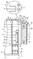
図1は本発明の第1実施形態に係る拡開掘削装置の正断面図、図2(A)は同拡開掘削装置の平面図、(B)は同拡開掘削装置の右側面図である。図1、図2に示すように、本第1実施形態に係る拡開掘削装置1は、下端部に切刃2が形成された円筒状のケーシング3の下部に設けられる装置である。
Embodiments of the present invention will be described below.
(First embodiment)
FIG. 1 is a front sectional view of an expanded excavator according to the first embodiment of the present invention, FIG. 2 (A) is a plan view of the expanded excavator, and FIG. 1 (B) is a right side view of the expanded excavator. is there. As shown in FIGS. 1 and 2, the expanded
拡開掘削装置1は、ケーシング3の下部内側に着脱可能に固定される直方体状の基台部4と、側方に開口した角筒を上下2段に配置した形状に形成され、上部を基台部4に外挿され、基台部4の長手方向に移動可能な第1腕部5と、第1腕部5の下部に移動可能に挿入されて先端部にビット26〜28を固定し、側方に直線的に移動して、ケーシング3の外周面より外側に突出可能な直方体状の第2腕部7とを備えている。
The
ケーシング3の内周面の対向する2カ所には、基台部4をケーシング3の下方に案内するガイドレール部8がケーシング3の中心線に平行に設けられている。ガイドレール部8の下端部には、上部から挿入される拡開掘削装置1をケーシング3の下端部で保持するために上方に開口するコ字状に形成されたストッパ部46が、ガイドレール部8の下端を覆うように設けられている。
Two
基台部4の両端部9,10は、ケーシング3の内径に合わせて凸となる円弧状に形成されている。また、基台部4の第2腕部7の突出方向とは逆側には、基台部4と同じ矩形の断面形状を有するスペーサ部材11,12がボルト等の締結部材を用いて着脱可能に締結固定されている。スペーサ部材11,12は、基台部4側の端部が凹となり、その逆側が凸となっている。スペーサ部材11,12を取り付けない場合の基台部4の長さは、1500mmより少し小さく形成されており、スペーサ部材11,12の長さは、それぞれ300mm,200mmに形成されている。かかる構成によって、1台の拡開掘削装置1を、1500mm,1800mmまたは2000mmの直径のケーシングに使用することができる。
Both
基台部4の両端部9,10およびスペーサ部材11,12の凸側の端部には、ガイドレール部8に被さって上下に摺動移動可能なレールガイド部37〜40が縦方向に形成されている。
第1腕部5の上下には、基台部4および第2腕部7をそれぞれ挿入した矩形の貫通孔14,15がそれぞれ形成され、貫通孔14,15は、仕切り板16により仕切られている。
Rectangular through
基台部4の下部中央には、貫通孔13が形成されており、仕切り板16の上部には、貫通孔13から基台部4の内部にロッド固定部17が突出して設けられている。
基台部4の上側の貫通孔14の内部には、油圧シリンダ18が設けられている。油圧シリンダ18の基側は、基台部4の一端部9に固定され、油圧シリンダ18の先側は、ロッド固定部17に固定されている。
A through
A
基台部4の下側の貫通孔15の内部に配置された第2腕部7の内部には、油圧シリンダ19が設けられている。油圧シリンダ19の基側は、第1腕部5の一端部9に固定され、油圧シリンダ18の先側は、第2腕部7に固定されている。
A
第1腕部5の上部には、油圧シリンダ18,19に作動油を供給する可撓性の給油管20〜23を挿通する長孔が上下に貫通して形成されている。
また、第1腕部5の上部の長手方向両端部には、拡開掘削装置1をケーシング3の内部に挿入して下降させ、また上昇させて取り出すときに、ワイヤを連結する吊り下げ用部材24がそれぞれ設けられている。
In the upper part of the
In addition, at both ends in the longitudinal direction of the upper portion of the
第2腕部7は、第1腕部5の下側の貫通孔15から他側の端部10側に突出するとともに縦置きして配置されたビット固定板25を有し、このビット固定板25には、1又は2以上、例えば3本のビット26〜28が設けられている。
The
ビット26〜28は、このビット固定板25の一側面にそれぞれ斜め上方、水平方向、斜め下方に向けて固定されているが、地盤の性質により方向を変えて取り付けることができる。
The
ビット固定板25の下部には、ビット26〜28で掘削した土砂を拡開掘削装置1の下部中央に搬送するための溝状案内部材29が固定されている。溝状案内部材29は、ビット固定板25とともに側方に進退することができる。
A groove-shaped
図3(A)は同拡開掘削装置の側面図、(B)は同拡開掘削装置の使用中の状態を示す正断面図、図4は、同拡開掘削装置の使用後の状態を示す正面図である。図3(A)、(B)、図4に示すように、基台部4の下部には、円筒状に形成された側壁30と、側壁30の下部に設けられた開閉可能な蓋部31と、側壁30の上部に設けられた天板部材32とを備えた集積バケット41が基台部4に着脱可能に設けられている。
側壁30内には、基台部4、第1腕部5および第2腕部7が上下動可能な直方体状の移動用空間部47が形成されている。移動用空間部47は、集積バケット41内の他の空間部とは隔離されており、土砂が侵入しないように形成されている。
集積バケット41の蓋部31には、V字状の2カ所の切欠き部44が形成され、この切欠き部44を覆うゴム板等の可撓性部材からなる弁体45が設けられている。弁体45の一端(図4の斜線部分)は、切欠き部44の周方向の一側の辺に沿って固定され、他端は蓋部31の上面に当接している。
FIG. 3A is a side view of the expanded excavator, FIG. 3B is a front sectional view showing a state in which the expanded excavator is in use, and FIG. 4 shows a state after use of the expanded excavator. FIG. As shown in FIGS. 3A, 3 </ b> B, and 4, at the lower part of the
In the
The
ケーシング3を周方向の一側に回転させながら下方に押し下げると、ケーシング3の下部に滞留している土砂が弁体45を押し上げながら切欠き部44を通過して集積バケット44の内部に収容される。ケーシング3を逆に回転させるとき、またはケーシング3を上方に移動させるときには、弁体45は開かず、集積バケット41内の土砂はこぼれ落ちることはない。
When the
蓋部31は、頂点を下方に突出させた逆円錐状に形成されている。蓋部31には、天板部材32に設けられた操作部材33によって開閉可能な固定部34が設けられている。
The
次に拡開掘削装置1の動作について説明する。拡開掘削装置1は、給油管20〜23に作動油を送り込むことによって、油圧シリンダ18,19のロッドを進退させ、このロッドの進退により第1腕部5および第2腕部7を直線的に移動させ、ビット26〜28をケーシングの外周面より外側に突出させることができる。
Next, operation | movement of the
図1、図2に示すように、拡開掘削装置1の初期状態においては、油圧シリンダ18,19のロッドは収縮した状態で、第1腕部5および第2腕部7も収縮した状態となっている。このときのビット26〜28の先端は、ケーシング3の内周面より中心側に配置されている。
As shown in FIGS. 1 and 2, in the initial state of the
給油管20に油圧を加えると、油圧シリンダ18のロッドが伸張して、第1腕部5がケーシング3の半径方向外側に移動し、ビット26〜28が、ケーシング3の外周面より外側に突出する。この状態で、ケーシング3を回転させることによって、ビット26〜28でケーシング3の外周面より半径方向外側の土砂を掘削することができる。掘削された土砂は、溝状案内部材29内に入る。掘削を継続することによって、土砂はケーシング3の中心方向に移動し、集積バケット41内に集積される。
When hydraulic pressure is applied to the
次いで、給油管22に油圧を加えると、油圧シリンダ19のロッドが伸張して、第2腕部7がケーシング3の半径方向外側に移動し、ビット26〜28が、さらに外側に移動する。この状態で、ケーシング3を回転させることによって、ビット26〜28でさらに外側の土砂を掘削することができる。
Next, when oil pressure is applied to the
掘削後は、給油管21、23に油圧を加えると、油圧シリンダ18,19のロッドが収縮する。
After excavation, when hydraulic pressure is applied to the
なお、油圧シリンダ18を収縮させた状態で、油圧シリンダ19のロッドを伸張させることも可能である。例えば、油圧シリンダ18,19のストロークをそれぞれ40cm、60cmとすると、設定可能な拡大半径は、40cm、60cm、100cmの3種類となる。この拡大幅はオペレータにより管理されており、オペレータはケーシング3の外側から拡大幅を自由に設定することができる。
The rod of the
図3(A)、(B)に示すように、集積バケット41は、基台部4に対して自由に上下動でき、空間部36の底面によって高さ位置が決まる。空間部36の高さが低いときには、集積バケット41は、基台部4に対する相対位置が上昇する。このとき基台部4は、集積バケット41内の移動用空間部47内を下側に移動することになる。また、図3(B)に示すように、空間部36の高さが高いときは、基台部4は移動用空間部47内を上側に移動することになる。
As shown in FIGS. 3A and 3B, the stacking
次に拡開掘削装置を用いた杭底拡大工法について説明する。
図5(A)〜(E)は、杭底拡大工法の作業手順を示す説明図である。図5(A)〜(E)に示すように、杭底拡大工法は、下端部に切刃2が形成された円筒状のケーシング3を用いて地盤を掘削し、ケーシング3内に基礎を構築する工法において、拡開掘削装置1を用いたものである。
Next, the pile bottom expansion method using the expansion excavation apparatus will be described.
5 (A) to 5 (E) are explanatory views showing a work procedure of the pile bottom expansion method. As shown in FIGS. 5 (A) to 5 (E), the pile bottom expansion method excavates the ground using a
(掘削)
図5(A)に示すように、現場に全周回転機35を設置し、ケーシング3を規定の深度まで回転圧入して地盤を掘削し、ケーシング3内の土砂をハンマーグラブ43を用いて除去する。
(Drilling)
As shown in FIG. 5A, an all-
(拡径準備)
図5(B)に示すように、ケーシング3を、拡大計画に基づいて必要ストロークだけ持ち上げて全周回転機35で支持し、ケーシング3の下部に空間部36を形成する。空間部36の高さは、ケーシング3に拡開掘削装置1を装着して作動可能となる高さ以上とする。
(Preparation for diameter expansion)
As shown in FIG. 5B, the
(拡開掘削装置挿入)
次いで、図5(B)、(C)に示すように、拡開掘削装置1のレールガイド部37,40を、クレーン等の吊り下げ手段を用いて、ケーシング3のガイドレール部8に外挿し、レールガイド部37,40がストッパ部に掛止するまで徐々に降ろす。なお、ストッパ部とは別に掛合部を形成しておき、拡開掘削装置1のケーシング3に対する上下動を防止する構造を追加することも可能である。例えば、レールガイド部の下端部のガイドレール部8と同じ長さ分だけを、周方向にオフセットしておくと、拡開掘削装置1がストッパ部に当接して停止した後に、ケーシング3を周方向に回転させると、拡開掘削装置1のガイドレール部8が、レールガイド部の下端部のオフセット部分に掛合して外れなくなる。
(Expansion drilling device inserted)
Next, as shown in FIGS. 5B and 5C, the
(拡開)
図5(D)に示すように、ケーシング3の上部に板状操作盤42を被せる。この板状操作盤42上では、給油管20〜23の開閉操作や、油圧の供給、または全周回転機35の制御を行うことができる。これらの制御状態を示す電気パネルやディスプレイを設置することによって、拡開操作中の管理を目視で確認することができる。
(Expansion)
As shown in FIG. 5D, a plate-
第1、第2の腕部5,7を伸縮させて、ビット26〜28を所定の長さだけ突出させ、ケーシング3を回転させることによって、周囲の土砂が掘削され、ケーシング3の下部の空間部36を拡径することができる。
The first and
図3(B)に示すように、拡開作業を行うことによって、集積バケット41内に土砂が集積される。拡開作業は、空間部36の上部側から行われる。掘削された土砂は、まだ拡開を終えていない下部の地盤によって落下しないように支持され、土砂の集積バケット41への誘導が効率よく行われる。空間部36の上部側から下部側に向かって掘削が進むにつれ、基台部4は、集積バケット41内の下側に移動することになるが、集積バケット41内に移動用空間部47が設けられており、移動用空間部47内には土砂が入らないので、土砂の収容はスムーズに行われる。
As shown in FIG. 3 (B), earth and sand are accumulated in the
(排出)
図5(E)に示すように、第1、第2腕部5,7を縮めて拡開掘削装置1をケーシング3の上部から取り出し、蓋部31を開いて土砂を排出する。なお、集積バケット41の下部の切欠き部44からも残留スライムが取り入れられるので、完全なスライム処理が可能になる。
(Discharge)
As shown in FIG. 5 (E), the first and
(基礎構築)
ケーシング3および拡開掘削装置1によって形成された孔部内にコンクリートからなる基礎を構築する。ケーシング3は、コンクリートを打設しながら徐々に上方に引き抜く。
このようにして下部が拡径した基礎を構築することができる。
(第2実施形態)
図6は本発明の第2実施形態に係る昇降時の拡開掘削装置の正断面図、図7は同第2実施形態に係る拡底時の拡開掘削装置の正断面図、図8(A)は同拡開掘削装置の昇降時の平面図、(B)は同拡開掘削装置の拡底時の平面図である。
図6、図7に示すように、本発明の第2実施形態に係る拡開掘削装置51は、下端部に切刃52が形成された円筒状のケーシング53の下部に設けられる装置である。
(Foundation construction)
A foundation made of concrete is constructed in the hole formed by the
In this way, it is possible to construct a foundation whose lower part has an enlarged diameter.
(Second Embodiment)
FIG. 6 is a front sectional view of the expanded excavation apparatus during lifting according to the second embodiment of the present invention, FIG. 7 is a front sectional view of the expanded excavation apparatus during bottom expansion according to the second embodiment, FIG. ) Is a plan view when the expansion excavation apparatus is lifted and lowered, and (B) is a plan view when the expansion excavation apparatus is expanded.
As shown in FIGS. 6 and 7, the expanded
拡開掘削装置51は、吊りワイヤ54によりケーシング53の上部から内部に吊り下げられる基台部55と、この基台部55にケーシング53の内壁に向かって進退自在な複数の固定張出グリップ56と、基台部55のセンターポール57に基端を固定され他端を固定張出グリップ56に固定された油圧シリンダ58を有している。
The
ケーシング53の上端には架台59が設けられており、地上の油圧ユニット60からの油圧ホース61が、油圧スイベル62を介して回転自在に架台59に導かれている。油圧スイベル62に接続された油圧ホース63はホース巻き取りリール64を介して基台部55に導かれ、一部は油圧シリンダ58に分岐される。油圧ホース63はさらに基台部55の下部に導かれ、油圧パイプ65を介して開閉翼67開閉用の油圧シリンダ66に油圧を供給する。前記架台59には、吊りワイヤ54の下端部に固定された検測テープ68を巻き取りおよび巻き解くことにより拡開掘削装置51の吊り下げ深さを測定する検測リール69が設置されている。
A
開閉翼67は、基台部55の下方に連結された筒状フレーム71に設けられた垂直方向のヒンジ72により、内外方向に開閉するように構成されており、端部にはビット70が設けられている。油圧シリンダ66に油圧を供給することにより、図6の閉じた状態から図7の拡開した状態に駆動される。また筒状フレーム71の底部には蓋部73が設けられている。
The opening /
図9は、第2実施形態に係る拡開掘削装置51を用いた施工方法を実施するための全体構成図である。図において、80はケーシング53を継ぎ足しながら掘削していく全周回転掘削機、81は拡開掘削装置51を吊り下げる吊りワイヤ54を昇降するための掘削用クローラクレーン、82は拡開掘削装置51により掘削された土砂を搬送するダンプトラック、83は掘削土を積み込みや整地するための油圧ショベル、84は基礎コンクリート打設時に生コン車を全周回転掘削機80の上部の高さまで上らせるための生コン車架台、85は現場打設の基礎コンクリートの強度補強のために用いる鉄筋籠、86は溶接機、87はコンクリート打設用のトレミー管、88は現場での工事用電力の発電に使う発電機、89は洗浄作業に使う高圧洗浄機である。
FIG. 9 is an overall configuration diagram for carrying out a construction method using the expanded
次に拡開掘削装置を用いた杭底拡大工法について説明する。
(掘削)
図9に示すように、現場に全周回転掘削機80を設置し、ケーシング53を規定の深度まで回転圧入して切刃52により地盤を掘削し、ケーシング53内の土砂をハンマーグラブ(図示せず。図5(A)のハンマーグラブ43参照)を用いて除去する。
Next, the pile bottom expansion method using the expansion excavation apparatus will be described.
(Drilling)
As shown in FIG. 9, an all-
(拡径準備)
ケーシング53を、拡大計画に基づいて必要ストロークだけ持ち上げて全周回転掘削機80で支持し、ケーシング53の下部に空間部を形成する。空間部の高さは、ケーシング53に拡開掘削装置51を装着して作動可能となる高さ以上とする。
(Preparation for diameter expansion)
The
(拡開掘削装置挿入)
次いで、掘削用クローラクレーン81を用いて拡開掘削装置51をケーシング53の底部の空間部まで下ろす。このとき、架台59はケーシング53の上端に残った状態で、拡開掘削装置51のみが下降する。その下降位置は、ケーシング53の下端に固定張出グリップ56の下端がほぼ一致する位置である。次いで、油圧ユニット60により油圧シリンダ58に作動油を供給して固定張出グリップ56が外側に進出し、図8(b)に示すように、固定張出グリップ56のケーシング53内面との接触面の摩擦力で、拡開掘削装置51は不動状態に固定される。
(Expansion drilling device inserted)
Next, the expanding
(拡開)
図7に示すように、油圧ユニット60から油圧ホース63,油圧パイプ65を介して油圧シリンダ66に作動油を供給し、開閉翼67を外側に拡張する。当初は、ケーシング53の下部の空間部はケーシング53の外径とほぼ同じ径であるので、開閉翼67の拡張の度合いは小さい。次いで、全周回転掘削機80を用いてケーシング53を回転させる。このケーシング53の回転により、拡開掘削装置51も一体に回転するので、開閉翼67の端部に設けられたビット70により孔部の内周が掘削される。掘削が進むにつれて、開閉翼67を開くことで、図7に示すように孔部底部を台形状に拡開することができる。拡開により掘削された土砂は蓋部73と筒状フレーム71に囲まれた空間にかき集められる。蓋部73の頂部には取込穴が設けられており、底部スライムは取込穴よりすくい上げられ、かき集められる。
(Expansion)
As shown in FIG. 7, the hydraulic oil is supplied from the
(排出)
所定の計画値まで拡開作業が完了すると、油圧ユニット60により油圧シリンダ66を縮小して開閉翼67を閉じる。同時に、油圧シリンダ58の作動油も抜いて、固定張出グリップ56を後退させる。これにより、拡開掘削装置51とケーシング53の内周との間に隙間が生じ、固定状態が解除され、図6に示す状態となる。その状態で吊りワイヤ54を掘削用クローラクレーン81で吊り上げ、拡開掘削装置51をケーシング53の上部から取り出し、蓋部31を開いて土砂を排出する。
(Discharge)
When the expansion operation is completed to a predetermined plan value, the
(基礎構築)
ケーシング53および拡開掘削装置51によって形成された孔部内に鉄筋籠85を挿入し、コンクリートを打設して基礎を構築する。ケーシング53は、コンクリートを打設しながら徐々に上方に引き抜く。
このようにして下部が拡径した基礎を構築することができる。
(Foundation construction)
A reinforcing bar 85 is inserted into the hole formed by the
In this way, it is possible to construct a foundation whose lower part has an enlarged diameter.
この第2実施形態においては、油圧源を地上の油圧ユニット60とし、これより油圧スイベル62を介して拡開掘削装置51内部の油圧シリンダ58,66を駆動するようにしたので、第1実施形態のように板状操作盤42上での作業を無人化することができ、安全な作業が可能となる。また、ケーシングにガイドレール部8を形成する必要がなくなる。
In the second embodiment, the hydraulic power source is the ground
なお、上述した第2実施形態では、4個の固定張出グリップ56を伸縮させる手段として図8に示すように4個の油圧シリンダ58を用いた例を示したが、対向する固定張出グリップ同士を1対として立体交差させた2段の2個の油圧シリンダで駆動することもできる。また、図10に示すように、内周面にテーパを有する対向する固定張出グリップ56同士を2段の連結スライドバー74,75でスライド可能に連結し、固定張出グリップ56の内周面に周接するテーパ面を外周に形成した昇降コマ76を設け、連結スライドバー74と昇降コマ76とを1個の油圧シリンダで結合する構成とすることもできる。なお、対向する固定張出グリップ56同士を引き合うようにするバネ78,79を設ける。この構成とすることにより、油圧シリンダ77を伸ばした状態では図10(a),(b)に示すように固定張出グリップ56とケーシング53との間には隙間が形成されているが、油圧シリンダ77を縮めた状態では図10(c)に示すように昇降コマ76が上昇してテーパ面により固定張出グリップ56が外側に押され、固定張出グリップ56の外周がケーシング53の内周に圧接し、拡開掘削装置51をケーシング53に固定することができる。
In the second embodiment described above, an example in which four
本発明の拡開掘削装置は、オールケーシング工法に用いられるケーシングチューブ等の円筒状ドリルの内部に設けられて周囲の地盤の掘削を行う拡開掘削装置および杭底拡大工法として有用であり、特に、建築分野における高層ビルの基礎や、土木分野における橋梁下部の基礎の構築に適している。 The expansion excavation apparatus of the present invention is useful as an expansion excavation apparatus and a pile bottom expansion method for excavating the surrounding ground provided inside a cylindrical drill such as a casing tube used in the all casing method, It is suitable for building foundations for high-rise buildings in the construction field and foundations for bridges in the civil engineering field.
1 拡開掘削装置
2 切刃
3 ケーシング
4 基台部
5 第1腕部
7 第2腕部
8 ガイドレール部
9,10 端部
11,12 スペーサ部材
13 貫通孔
14,15 貫通孔
16 仕切り板
17 ロッド固定部
18 油圧シリンダ
19 油圧シリンダ
20〜23 給油管
24 吊り下げ用部材
25 ビット固定板
26〜28 ビット
29 溝状案内部材
30 側壁
31 蓋部
32 天板部材
33 操作部材
34 固定部
35 全周回転機
36 空間部
37〜40 レールガイド部
41 集積バケット
42 板状操作盤
43 ハンマーグラブ
44 切欠き部
45 弁体
46 ストッパ部
47 移動用空間部
51 拡開掘削装置
52 切刃
53 ケーシング
54 吊りワイヤ
55 基台部
56 固定張出グリップ
57 センターポール
58 油圧シリンダ
59 架台
60 油圧ユニット
61 油圧ホース
62 油圧スイベル
63 油圧ホース
64 ホース巻き取りリール
65 油圧パイプ
66 油圧シリンダ
67 開閉翼
68 検測テープ
69 検測リール
70 ビット
71 筒状フレーム
72 ヒンジ
73 蓋部
74,75 連結スライドバー
76 昇降コマ
77 油圧シリンダ
78,79 バネ
80 全周回転掘削機
81 掘削用クローラクレーン
82 ダンプトラック
83 油圧ショベル
84 生コン車架台
85 鉄筋籠
86 溶接機
87 トレミー管
88 発電機
89 高圧洗浄機
DESCRIPTION OF SYMBOLS 1 Expanding excavation apparatus 2 Cutting blade 3 Casing 4 Base part 5 1st arm part 7 2nd arm part 8 Guide rail part 9,10 End part 11,12 Spacer member 13 Through-hole 14,15 Through-hole 16 Partition plate 17 Rod fixing portion 18 Hydraulic cylinder 19 Hydraulic cylinder 20-23 Oil supply pipe 24 Hanging member 25 Bit fixing plate 26-28 Bit 29 Groove-shaped guide member 30 Side wall 31 Lid portion 32 Top plate member 33 Operation member 34 Fixing portion 35 Full circumference Rotating machine 36 Space part 37-40 Rail guide part 41 Stacking bucket 42 Plate-like operation panel 43 Hammer grab 44 Notch part 45 Valve body 46 Stopper part 47 Moving space part 51 Expanding excavator 52 Cutting blade 53 Casing 54 Hanging wire 55 Base unit 56 Fixed overhang grip 57 Center pole 58 Hydraulic cylinder 59 Mounting frame 60 Hydraulic pressure Knit 61 Hydraulic hose 62 Hydraulic swivel 63 Hydraulic hose 64 Hose take-up reel 65 Hydraulic pipe 66 Hydraulic cylinder 67 Opening and closing wing 68 Inspection tape 69 Inspection reel 70 Bit 71 Cylindrical frame 72 Hinge 73 Lid 74, 75 Connecting slide bar 76 Lifting frame 77 Hydraulic cylinder 78, 79 Spring 80 Full-rotation excavator 81 Crawler crane for excavation 82 Dump truck 83 Excavator 84 Ready-mixed vehicle chassis 85 Rebar rod 86 Welding machine 87 Toremy tube 88 Generator 89 High pressure washer
Claims (9)
前記ケーシングの下部内側に着脱可能に固定される基台部と、
前記基台部の下側に取り付けられて先端部にビットが固定され、前記ビットを前記ケーシングの外周面より外側に直線的に移動させて突出させる腕部とを備え、
前記腕部は、前記基台部に取り付けられ、側方に直線的に移動可能な第1腕部と、
前記第1腕部に取り付けられて先端部に前記ビットを固定し、側方に直線的に移動して、前記ケーシングの外周面より外側に突出可能な第2腕部とを備えていることを特徴とする拡開掘削装置。 An expanded excavator provided at the lower part of a cylindrical casing having a cutting edge formed at the lower end,
A base portion detachably fixed to the lower inner side of the casing;
An arm that is attached to the lower side of the base and has a bit fixed to a tip, and moves the bit linearly outward from the outer peripheral surface of the casing ;
The arm portion is attached to the base portion, and a first arm portion that is linearly movable laterally;
A second arm portion that is attached to the first arm portion, fixes the bit to the tip portion, moves linearly to the side, and protrudes outward from the outer peripheral surface of the casing ; A featured exploration rig.
前記ケーシングで地盤を掘削した後にケーシング内の土砂を除去する工程と、
前記ケーシングを少し持ち上げて前記ケーシングの下部に空間部を形成する工程と、
前記ケーシング内に、前記ケーシングの下部に固定される基台部、前記基台部の下側に取り付けられて先端部にビットが固定され、側方に直線的に移動可能な腕部および前記腕部の下方位置に配置された集積バケットを備えた拡開掘削装置を前記ケーシングの上部から挿入して下端部に固定する工程と、
前記腕部を伸ばして、前記ビットを前記ケーシングの外周面より外側に突出させ、前記拡開掘削装置を、前記ケーシングとともに回転させて地盤を掘削し、前記ケーシングの下部を拡径するとともに掘削した土砂を前記集積バケット内に収容する工程と、
前記腕部を縮めて前記拡開掘削装置をケーシングの上部から取り出した後、前記ケーシングおよび前記拡開掘削装置によって形成された孔部内にコンクリートからなる基礎を構築する工程とを備えていることを特徴とする杭底拡大工法。 In the method of excavating the ground using a cylindrical casing with a cutting edge formed at the lower end, and constructing a foundation in the casing,
Removing the earth and sand in the casing after excavating the ground with the casing;
Slightly lifting the casing to form a space in the lower part of the casing;
In the casing, a base part fixed to the lower part of the casing, an arm part attached to a lower side of the base part and having a bit fixed to a tip part, and linearly movable laterally and the arm A step of inserting an expanding excavator provided with an accumulation bucket disposed at a lower position of the part from the upper part of the casing and fixing it to the lower end part;
The arm is extended, the bit protrudes outward from the outer peripheral surface of the casing, the expansion excavator is rotated together with the casing to excavate the ground, and the lower portion of the casing is expanded and excavated. Storing earth and sand in the accumulation bucket;
A step of constructing a foundation made of concrete in the hole formed by the casing and the expansion excavation device after the arm portion is contracted and the expansion excavation device is taken out from the upper part of the casing. Pile-bottom expansion method that is characteristic.
前記ケーシングの下部内側に着脱可能に固定される基台部と、
前記基台部に取り付けられ、前記ケーシングの内面に向かって伸縮駆動される固定張出グリップと、
前記基台部の下側に取り付けられて先端部にビットが固定され、前記ビットを前記ケーシングの外周面より外側に拡開する開閉翼とを備えていることを特徴とする拡開掘削装置。 An expanded excavator provided at the lower part of a cylindrical casing having a cutting edge formed at the lower end,
A base portion detachably fixed to the lower inner side of the casing;
A fixed overhanging grip attached to the base and driven to extend and contract toward the inner surface of the casing;
An expansion excavation apparatus, comprising: an opening / closing blade attached to a lower side of the base portion, having a bit fixed to a tip portion thereof, and expanding the bit outward from an outer peripheral surface of the casing.
前記ケーシングで地盤を掘削した後にケーシング内の土砂を除去する工程と、
前記ケーシングを少し持ち上げて前記ケーシングの下部に空間部を形成する工程と、
前記ケーシング内に、前記ケーシングの下部内側に着脱可能に固定される基台部、前記基台部に取り付けられ、前記ケーシングの内面に向かって伸縮駆動される固定張出グリップ、前記基台部の下側に取り付けられて先端部にビットが固定され、前記ビットを前記ケーシングの外周面より外側に拡開する開閉翼を備えた拡開掘削装置を前記ケーシングの上部から挿入して、前記固定張出グリップをケーシングの内周に圧接するように伸ばすことにより前記拡開掘削装置を前記ケーシング下端部に固定する工程と、
前記開閉翼を伸ばして、前記ビットを前記ケーシングの外周面より外側に突出させ、前記拡開掘削装置を、前記ケーシングとともに回転させて地盤を掘削し、前記ケーシングの下部を拡径するとともに掘削した土砂を前記開閉翼内部に収容する工程と、
前記開閉翼を閉じて前記拡開掘削装置をケーシングの上部から取り出した後、前記ケーシングおよび前記拡開掘削装置によって形成された孔部内にコンクリートからなる基礎を構築する工程とを備えていることを特徴とする杭底拡大工法。 In the method of excavating the ground using a cylindrical casing with a cutting edge formed at the lower end, and constructing a foundation in the casing,
Removing the earth and sand in the casing after excavating the ground with the casing;
Slightly lifting the casing to form a space in the lower part of the casing;
In the casing, a base part detachably fixed to the lower inner side of the casing, a fixed overhanging grip attached to the base part and driven to extend and contract toward the inner surface of the casing, A spreading excavator equipped with an opening / closing blade attached to the lower side and having a bit fixed to the tip end and expanding the bit outward from the outer peripheral surface of the casing is inserted from the upper part of the casing, and the fixed tension Fixing the expanded excavation device to the lower end of the casing by extending the output grip so as to be in pressure contact with the inner periphery of the casing;
Extending the opening and closing wings, the bit protrudes outward from the outer peripheral surface of the casing, the expansion excavator is rotated together with the casing to excavate the ground, and the lower portion of the casing is expanded and excavated. Containing earth and sand in the open / close wing;
And a step of constructing a foundation made of concrete in a hole formed by the casing and the spread excavation device after closing the opening and closing blade and taking out the spread excavation device from the upper part of the casing. Pile-bottom expansion method that is characteristic.
Priority Applications (1)
| Application Number | Priority Date | Filing Date | Title |
|---|---|---|---|
| JP2004093433A JP3978469B2 (en) | 2003-07-31 | 2004-03-26 | Expansion drilling equipment and pile bottom expansion method |
Applications Claiming Priority (2)
| Application Number | Priority Date | Filing Date | Title |
|---|---|---|---|
| JP2003283595 | 2003-07-31 | ||
| JP2004093433A JP3978469B2 (en) | 2003-07-31 | 2004-03-26 | Expansion drilling equipment and pile bottom expansion method |
Publications (2)
| Publication Number | Publication Date |
|---|---|
| JP2005061205A JP2005061205A (en) | 2005-03-10 |
| JP3978469B2 true JP3978469B2 (en) | 2007-09-19 |
Family
ID=34380228
Family Applications (1)
| Application Number | Title | Priority Date | Filing Date |
|---|---|---|---|
| JP2004093433A Expired - Fee Related JP3978469B2 (en) | 2003-07-31 | 2004-03-26 | Expansion drilling equipment and pile bottom expansion method |
Country Status (1)
| Country | Link |
|---|---|
| JP (1) | JP3978469B2 (en) |
Families Citing this family (6)
| Publication number | Priority date | Publication date | Assignee | Title |
|---|---|---|---|---|
| JP4811654B2 (en) * | 2006-06-30 | 2011-11-09 | 株式会社進明技興 | Expanded root construction method and expanded excavator in all-casing method |
| KR100802943B1 (en) | 2006-09-30 | 2008-02-18 | 위성배 | Over cutting head apparatus for auger screw |
| KR101126590B1 (en) * | 2009-09-09 | 2012-03-23 | (주)부마씨이 | A Drilling System and A Drilling Method thereof |
| JP6099955B2 (en) * | 2012-12-06 | 2017-03-22 | 株式会社シロタ | Nakabori excavator |
| JP2014148833A (en) * | 2013-02-01 | 2014-08-21 | Tokugawa Kensetsu Co Ltd | Expansion drilling apparatus and expansion drilling method |
| CN117532047B (en) * | 2023-11-03 | 2024-04-16 | 上华电气有限公司 | Cabinet body drilling device for processing low-voltage switch cabinet |
-
2004
- 2004-03-26 JP JP2004093433A patent/JP3978469B2/en not_active Expired - Fee Related
Also Published As
| Publication number | Publication date |
|---|---|
| JP2005061205A (en) | 2005-03-10 |
Similar Documents
| Publication | Publication Date | Title |
|---|---|---|
| US6540443B2 (en) | Apparatus for and a method of boring the ground | |
| JP6081100B2 (en) | Existing pile pulling device | |
| JP3978469B2 (en) | Expansion drilling equipment and pile bottom expansion method | |
| JPH0543011B2 (en) | ||
| JP4747193B2 (en) | Low head drilling rig | |
| JP3361776B2 (en) | Crushing equipment for underground piles | |
| KR101263944B1 (en) | boring equipment | |
| JP2020159125A (en) | Establishing method of pile hole for diameter expanding pile | |
| JP2020143440A (en) | Pile press-in machine and pile press-in construction method | |
| JP3451275B2 (en) | Deep foundation excavator | |
| JP2008013971A (en) | Bucket for diameter-widening excavation | |
| KR890003263B1 (en) | Method and apparatus of exca-vating vertical tunnel | |
| JPH11229740A (en) | Subsoil excavation method and device | |
| JPH10205263A (en) | Earth-removing device for excavator | |
| JP2001182060A (en) | Pile press-in system and pile press-in method | |
| JP3046249B2 (en) | Vertical hole drilling method | |
| KR100479514B1 (en) | Apparatus for and a method of boring the ground | |
| JP2002138474A (en) | Method and device for cutting and pulling out existing pile | |
| JPH06221077A (en) | Method and device for preventing deflection of rotary excavating device | |
| JP7061526B2 (en) | Excavation method and excavation equipment | |
| JPH0624425Y2 (en) | Excavation body guiding device for excavation equipment such as pilot holes for pile driving | |
| JP3091134B2 (en) | Shaft excavator and construction method | |
| GB2114185A (en) | Method for boring vertical hole and machine therefor | |
| JP2007009671A (en) | Device and method for removing existing pile | |
| JPH073049B2 (en) | Construction method for steel pipe piles |
Legal Events
| Date | Code | Title | Description |
|---|---|---|---|
| A621 | Written request for application examination |
Free format text: JAPANESE INTERMEDIATE CODE: A621 Effective date: 20050420 |
|
| A131 | Notification of reasons for refusal |
Free format text: JAPANESE INTERMEDIATE CODE: A131 Effective date: 20061107 |
|
| A521 | Written amendment |
Free format text: JAPANESE INTERMEDIATE CODE: A523 Effective date: 20061226 |
|
| A01 | Written decision to grant a patent or to grant a registration (utility model) |
Free format text: JAPANESE INTERMEDIATE CODE: A01 Effective date: 20070410 |
|
| A61 | First payment of annual fees (during grant procedure) |
Free format text: JAPANESE INTERMEDIATE CODE: A61 Effective date: 20070502 |
|
| R150 | Certificate of patent or registration of utility model |
Free format text: JAPANESE INTERMEDIATE CODE: R150 |
|
| FPAY | Renewal fee payment (event date is renewal date of database) |
Free format text: PAYMENT UNTIL: 20100706 Year of fee payment: 3 |
|
| FPAY | Renewal fee payment (event date is renewal date of database) |
Free format text: PAYMENT UNTIL: 20100706 Year of fee payment: 3 |
|
| S111 | Request for change of ownership or part of ownership |
Free format text: JAPANESE INTERMEDIATE CODE: R313113 |
|
| FPAY | Renewal fee payment (event date is renewal date of database) |
Free format text: PAYMENT UNTIL: 20100706 Year of fee payment: 3 |
|
| R350 | Written notification of registration of transfer |
Free format text: JAPANESE INTERMEDIATE CODE: R350 |
|
| FPAY | Renewal fee payment (event date is renewal date of database) |
Free format text: PAYMENT UNTIL: 20100706 Year of fee payment: 3 |
|
| FPAY | Renewal fee payment (event date is renewal date of database) |
Free format text: PAYMENT UNTIL: 20110706 Year of fee payment: 4 |
|
| LAPS | Cancellation because of no payment of annual fees |