JP4788986B2 - Linear motor - Google Patents
Linear motor Download PDFInfo
- Publication number
- JP4788986B2 JP4788986B2 JP2001140605A JP2001140605A JP4788986B2 JP 4788986 B2 JP4788986 B2 JP 4788986B2 JP 2001140605 A JP2001140605 A JP 2001140605A JP 2001140605 A JP2001140605 A JP 2001140605A JP 4788986 B2 JP4788986 B2 JP 4788986B2
- Authority
- JP
- Japan
- Prior art keywords
- leg
- permanent magnet
- electromagnet
- linear motor
- field yoke
- Prior art date
- Legal status (The legal status is an assumption and is not a legal conclusion. Google has not performed a legal analysis and makes no representation as to the accuracy of the status listed.)
- Expired - Fee Related
Links
Images


Classifications
-
- H—ELECTRICITY
- H02—GENERATION; CONVERSION OR DISTRIBUTION OF ELECTRIC POWER
- H02K—DYNAMO-ELECTRIC MACHINES
- H02K41/00—Propulsion systems in which a rigid body is moved along a path due to dynamo-electric interaction between the body and a magnetic field travelling along the path
- H02K41/02—Linear motors; Sectional motors
- H02K41/03—Synchronous motors; Motors moving step by step; Reluctance motors
Description
【0001】
【発明の属する技術分野】
本発明は界磁ヨークに永久磁石を埋め込んだリニアモータに関する。
【0002】
【従来の技術】
リニアモータまたはパルスモータにおいて、永久磁石を設けたものが多く提案されており、永久磁石を設ける方法に注目すると、次に記載するようなものがある。
【0003】
励磁用コイルが設けられた鉄心の上方付近に、鉄心に接合された永久磁石を設け、該永久磁石を鉄心との間で挟持する磁極板を設けたバリアブルレラクタンス形リニアパルスモータ(特開昭63−294252号公報参照)がある。また、永久磁石を分割して配置したもの(特開平2−307356号公報、特開平2−32750号公報)もある。
【0004】
しかしながらこの特開昭63−294252号公報、特開平2−307356号公報および特開平2−32750号公報に開示されたリニアパルスモータでは、永久磁石を励磁側上方に設けたために鉄心を小型化できないという問題がある。
【0005】
固定子の上下両面側にそれぞれ配置され互いに機械的に固定された第1および第2の移動子をそれぞれU字状コアで形成し、該コアを2分割してその間に永久磁石を一方から他方へ磁束を流すように配置し、該コアに励磁巻線を施したリニアパルスモータ(特開昭64−47258号公報)がある。
【0006】
しかしこの特開昭64−47258号公報に開示されたリニアパルスモータでは、永久磁石が励磁側に設けられていて、励磁側を小型化できないという問題がある。
【0007】
また、移動子励磁側の鉄心歯に永久磁石を設けると共に、未着磁部分にスリットを設けたリニアパルスモータ、固定子の鉄心歯に永久磁石を設けると共に、未着磁部分にスリットを備えたスリット板を設けたリニアパルスモータ(特開平1−298945号公報)がある。
【0008】
しかしこの特開平1−298945号公報に開示されたリニアパルスモータでは、スリット板を含む鉄心を小型化できないという問題がある。
【0009】
また、移動子の電磁石を構成する磁極の先端に前記電磁石による起磁力の方向と直交する方向に起磁力を発生する永久磁石、または前記電磁石による起磁力の方向と平行する方向に起磁力を発生する永久磁石を設けたリニアパルスモータ(特開平2−114852号公報)がある。
【0010】
しかしこの特開平2−114852号公報に開示されたリニアパルスモータでは、磁極先端に永久磁石を設けるために、電磁石を小型化できないという問題がある。
【0011】
また、外周軸方向に小歯が配設された磁気ブロックとこれを所定の磁極に磁化する永久磁石を備え、この永久磁石によって磁極ブロックが互いに異極の磁性に磁化され、一方の磁極ブロックの歯先が固定子の突極の歯先に対向するとき、他方の磁極ブロックの歯先は固定子の突極の歯底と対向するようにしたリニアパルスモータ(特開平6−197517号公報)がある。
【0012】
しかしこの特開平6−197517号公報に開示されたリニアパルスモータでは磁極ブロックが存在するために小型化できないという問題がある。
【0013】
また、外周面に固定子小歯に対向して軸方向に等ピッチで複数個の移動子小歯が形成された移動子鉄心を有する移動子において、移動子の軸と移動子鉄心との間に、非磁性材からなる円筒状部材を設けたリニアパルスモータ(特開平7−170719号公報、特開平8−9623号公報)がある。
【0014】
しかしこの特開平7−170719号公報および特開平8−9623号公報に開示されたリニアパルスモータでは移動子の軸と移動子鉄心との間の円筒状部材の存在のために小型化できないという問題がある。
【0015】
また、軸方向に所定間隔隔てて配設された移動子鉄心をそれぞれN極およびS極に磁化するための永久磁石を備え、移動子軸は磁性材または非磁性材からなり、永久磁石は円筒状に形成され、かつ移動鉄心と移動子軸との間に配設されたリニアパルスモータ(特開平7−288969号公報)がある。
【0016】
しかしこの特開平7−288969号公報に開示されたリニアパルスモータでは永久磁石の存在のために小型化できないという問題がある。
【0017】
また、軸方向に所定間隔隔てて配設された移動子コア間に軸方向に着磁された永久磁石を介在させたリニアパルスモータ(特開平8−163857号公報)がある。
【0018】
しかしこの特開平8−163857号公報に開示されたリニアパルスモータでは永久磁石が存在するために小型化できないという問題がある。
【0019】
また、固定子として機能する1/8ピッチの間隔で並んだ複数の励磁ユニット群に、所定の空隙隔てて設けられ、永久磁石と磁性体からなる歯部が所定のピッチで交互に並んだ可動子としての磁極ユニットで構成され、1つの励磁ユニットは磁極ユニットを両側から挟むように並ぶ磁極と、該磁極を連結する磁性部材と、磁性部材に巻き回された電機子コイルを備えたリニアパルスモータ(特開平10−327571号公報)がある。
【0020】
しかし、この特開平10−327571号公報に開示されたリニアパルスモータでは永久磁石が存在するために小型化できないという問題がある。
【0021】
また、複数個の移動子小歯が形成された移動子内に配設された永久磁石を備え、移動子小歯は固定子小歯のピッチの1/2間隔で配設され、1つの小歯と小歯との間に軸方向に着磁された永久磁石を挟み一対の移動子コアを構成し、対同士の間には、空隙または非磁性材を介して磁気的に絶縁したリニアパルスモータ(特開平11−41905号公報)がある。
【0022】
しかしこの特開平11−41905号公報に開示されたリニアパルスモータでは、移動子を小型化できないという問題がある。
【0023】
【発明が解決しようとする課題】
しかしながら、永久磁石を用いた上記リニアパルスモータでは、小型化が困難な他に、十分な推力を持たないという問題点があった。
【0024】
本発明は、構成が簡単で、かつ小型化できる上に十分な推力を有するリニアモータを提供することを目的とする。
【0025】
【課題を解決するための手段】
本発明のリニアモータは、磁性体からなる界磁ヨークに長さ方向に所定ピッチで埋め込まれた複数の永久磁石と、
予め定めた間隔の極ピッチを有し、界磁ヨークの長さ方向に沿って所定ピッチで設けられると共に、界磁ヨークに対向して所定ギャップ隔てて設けられた複数の電磁石とを備え、
隣り合う永久磁石は互いに逆向きに着磁されたことを特徴とする。
【0026】
本発明のリニアモータによれば、界磁ヨークに所定のピッチで埋め込まれた永久磁石の磁極と永久磁石間の界磁ヨーク部分に形成される磁極と磁化により電磁石に形成される磁極との間の極性に基づく吸引力と反発力とによって、界磁ヨークと電磁石との間に推力が発生し、界磁ヨークと電磁石側との一方が相対的に駆動される。
【0027】
本発明のリニアモータにおいて、界磁ヨークに埋め込まれた永久磁石のピッチの間をτp、電磁石の極ピッチをτe、電磁石間のピッチをτg、励磁相の相数をm、nを0、1、2、3…、sを1、2、3…、としたとき
τe≒(2n+1)τp …(3)
τg=(2s+1/m)τe …(4)
とすることを特徴とする。
【0028】
本発明のリニアモータによれば、永久磁石が界磁ヨークにピッチτp≒(2n+1)/τeで埋め込まれ、電磁石間のピッチτgは、τg=(2s+1/m)τeの位置に形成されるために、ステップ幅τe/mで界磁ヨークまたは電磁石が一方の方向に駆動される。
【0029】
本発明のリニアモータにおいて、電磁石の鉄心はヨークで連結された異なる極性の磁極を発生させるための2脚を有し、各脚を連結するヨーク部分にコイルを巻き回したものであることを特徴とする。
【0030】
本発明のリニアモータによれば、各脚を連結するヨーク部分に巻き回されたコイルに通電することによって、各脚のそれぞれを異なる極性に磁化することができる。
【0031】
本発明のリニアモータにおいて、電磁石の鉄心はヨークで連結されて異なる極性の磁極を発生させるための2脚を有し、それぞれの脚に逆巻き方向に巻き回することによって差動コイルを構成し、差動コイルに通電することによって各脚を異なる極性に磁化させることを特徴とする。
【0032】
本発明のリニアモータによれば、差動コイルに通電することによって各脚のそれぞれを異なる極性に磁化することができる。
【0033】
本発明のリニアモータにおいて、電磁石は3脚を有し、中央の脚に巻き回されたコイルを有し、該コイルに通電することにより中央の脚を挟む両外側の脚を異なる極性に磁化させることを特徴とする。
【0034】
本発明のリニアモータによれば、3脚の中央の脚に巻き回されたコイルに通電することによって電磁石の両外側の脚のそれぞれを異なる極性に磁化することができる。
【0035】
【発明の実施の形態】
本発明にかかるリニアモータの実施の形態について説明する。
【0036】
図1は本発明の実施の一形態にかかるリニアモータ10の構成図である。
【0037】
このリニアモータ10は、ベース12上に固定されたステータブロック14と、前記ステータブロック14を貫通して図示しないガイドの案内作用の下に矢印Z方向に沿って変位自在に設けられた界磁ヨーク1とを有する。
【0038】
図2および図3は本発明の実施の一形態にかかるリニアモータ10の構成を示す模式説明図である。
【0039】
磁性体である例えば積層鉄心、または積層珪素鋼板からなる界磁ヨーク1に予め定めた一定の間隔、例えば環状に形成された永久磁石2−0、2−1、2−2、…、2−nが、界磁ヨーク1の表面と同一表面を形成するように例えばピッチτpで埋め込まれている。隣り合う永久磁石2−(n−1)と永久磁石2−nとは互いに逆向きに、例えばNS、SN、NS、SN、…の如くに着磁されている。したがって永久磁石間の界磁ヨーク1の凸部にはS極とN極とが交互に発生する。
【0040】
一方、界磁ヨーク1に対向して所定間隔のギャップを有して界磁ヨーク1側が開かれた断面U字状の積層珪素鋼板からなる電磁石鉄心3−1と電磁石鉄心3−1に巻き回されたコイル3−2とからなる電磁石3と、界磁ヨーク1に対向して所定間隔のギャップを有して界磁ヨーク1側が開かれた断面U字状の積層珪素鋼板からなる電磁石鉄心4−1と電磁石鉄心4−1に巻き回されたコイル4−2とからなる電磁石4が設けてある。
【0041】
ここで、図2および図3では励磁相を2つ設け、1相励磁の場合を例示しており、以下、電磁石3を励磁相Aとも記し、電磁石4を励磁相Bとも記す。
【0042】
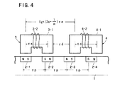
ここで、図4に示すように、界磁ヨーク1に埋め込まれた永久磁石2−0、2−1、2−2、…、のピッチはτpに設定してあり、電磁石鉄心3−1の脚間のピッチ、すなわち電磁石3の励磁による磁化により電磁石鉄心3−1の脚部に生成される磁極の中心位置間の距離である極ピッチおよび電磁石鉄心4−1の脚間のピッチすなわち電磁石4の励磁による磁化により電磁石鉄心4−1の脚部に生成される磁極の中心位置間の距離である極ピッチはτeに設定してあり、極ピッチτeと永久磁石間のピッチτpとの間には
τe≒(2n+1)τp …(5)
の関係がある。
【0043】
ここで、n=0、1、2、3…であり、≒と表現したのは推力の変動を抑圧するため多少ずらせる場合もあるためである。
【0044】
また、電磁石3と電磁石4との間のピッチτgは
τg=(2s+1/m)τe …(6)
に設定してある。
【0045】
ここで、s=1、2、3…であり、m=励磁相の相数である。
【0046】
また、隣り合う電磁石3と電磁石4との間の間隔τdは、電磁石鉄心の脚の幅をτe/mとすると、相数m=2のときにはτd=τeであり、相数m=3のときはτd=2τe/3であり、相数m=5のときはτd=2τe/5である。
【0047】
また、隣り合う電磁石3と電磁石4との間の間隔τdは、電磁石鉄心の脚の幅をτe/2とすると、相数m=2のときにはτd=τeであり、相数m=3のときはτd=5τe/6であり、相数m=5のときはτd=7τe/10である。
【0048】
図2Aに示す如く、電磁石3および4が無励磁の初期位置において、電磁石3の脚が永久磁石2−1、永久磁石2−2にほぼ対向し、電磁石4の一方の脚が永久磁石2−3と永久磁石2−4との間の界磁ヨーク部分にほぼ対向し、電磁石4の他方の脚が永久磁石2−4と永久磁石2−5との間の界磁ヨーク部分にほぼ対向しているものとする。
【0049】
この状態で、永久磁石2−1と永久磁石2−2との間の界磁ヨーク部分から電磁石鉄心3−1の一方の脚を通して永久磁石2−1のS極の方向に磁界φpが発生し、永久磁石2−1と永久磁石2−2との間の界磁ヨーク部分から電磁石鉄心3−1の他方の脚を通して永久磁石2−2のS極の方向に磁界φpが発生し、永久磁石2−3と永久磁石2−4との間の界磁ヨーク部分から永久磁石2−4のS極の方向に電磁石鉄心4−1を通して磁界φpが発生する。
【0050】
励磁相Aの初期位置にある図2Aの状態から、コイル3−2、すなわち、励磁相Aを図2Bに示す方向に通電する。この通電によって電磁石3は磁化されて反時計方向に磁界φcが発生し、電磁石鉄心3−1の一方の脚と、永久磁石2−0と永久磁石2−1との間の界磁ヨーク部分との間で吸引力が働き、電磁石鉄心3−1の他方の脚と、永久磁石2−1と永久磁石2−2との間の界磁ヨーク部分との間で吸引力が働いて、推力が発生する。
【0051】
上記した励磁相Aの励磁による吸引力によって図2Cに示すようにτe/mにて定まる1ステップ幅だけ界磁ヨーク1が図2において右方向に移動する。続いて励磁が一旦停止される。この状態は図3Aに示すように励磁相Aの通電終了、すなわち励磁相Bの初期位置の状態となる。このときの状態は励磁相Aの初期位置の場合から容易に類推されるとおりであり、励磁相Aの初期位置の場合と同様である。
【0052】
図3Aにおける励磁相Bの初期位置に次いで、励磁相Bが励磁される。上記の励磁相Bの初期位置にある状態から、コイル4−2、すなわち、励磁相Bに図3Bに示す方向に通電する。この通電によって電磁石鉄心4−1に反時計方向に磁界φcが発生し、電磁石鉄心4−1の一方の脚と、永久磁石2−2と永久磁石2−3の間の界磁ヨーク部分との間で吸引力が働き、電磁石鉄心4−1の他方の脚と、永久磁石2−3と永久磁石2−4との間の界磁ヨーク部分との間で吸引力が働いて、推力が発生し、続いてτe/mにて定まる1ステップ幅だけ界磁ヨーク1が図3において右方向に移動される。
【0053】
このように、本発明の実施の一形態にかかるリニアモータ10では推力が生じ、界磁ヨーク1が駆動される。
【0054】
このとき界磁ヨーク1に生ずる変位に対する推力特性は図5の実線に示す如くであり、ディテント力特性は図5の破線に示す如くである。
【0055】
また、電磁石による起磁力と推力との関係を、本発明の実施の一形態にかかるリニアモータ10の場合と、ハイブリッドリニアモータの場合と、バリアブルリラクタンスリニアモータの場合とを比較したところ図6に示す如くであった。図6において、本発明の実施の一形態にかかるリニアモータ10の場合を実線で示し、ハイブリッドリニアモータの場合を破線で示し、バリアブルリラクタンスリニアモータの場合を一点鎖線で示している。
【0056】
このように、本発明の実施の一形態にかかるリニアモータ10によれば、界磁ヨーク1に永久磁石を埋め込んだ結果、
(a)電磁石3、4の電磁石鉄心3−1、4−1の脚に発生する推力の方向を揃えることができて、従来のバリアブルリラクタンスリニアモータ、ハイブリッドリニアモータの場合の約2倍の推力が得られる。
【0057】
(b)界磁ヨーク1に永久磁石を埋め込むことによって、DCモータの推力であるフレミング左手則による力ばかりでなく、バリアブルリラクタンスリニアモータの推力であるリラクタンス力も発生させることができて、これらの力が作用して従来のリニアモータに比較して本発明の実施の一形態にかかるリニアモータ10の場合、小型で大きな推力が発生するのである。
【0058】
(c)電磁石3、4を励磁相数に基づいて順次配列することによって、電磁石の磁気回路が1相毎に独立しているため、例えば1相励磁、1−2相励磁などの様々な励磁方法を採用することができるほか、各相を磁気的に連結するヨークを必要としないため、小型化が達成できる。
【0059】
なお、上記においては、界磁ヨーク1が移動する場合を例示したが、電磁石3、4側が移動するようにすることもできる。
【0060】
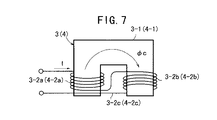
また、電磁石3、4を図4に示す構成に代わって、図7に示すごとく電磁石鉄心3−1(4−1)の一方の脚に一方向にコイル3−2a(4−2a)を巻き回し、電磁石鉄心3−1(4−1)の他方の脚に他方向にコイル3−2b(4−2b)を巻き回し、両コイル3−2a(4−2a)と3−2b(4−2b)とを直列に接続して差動コイル3−2c(4−2c)としたものでもよい。差動コイル3−2c(4−2c)に通電することによって電磁石鉄心3−1(4−1)の一方の脚と電磁石鉄心3−1(4−1)の他方の脚とで異なる極性に磁化される。
【0061】
次に、2相駆動の場合について、図8〜図10によって説明する。
【0062】
図8〜図10において界磁ヨーク1と電磁石3、4との間のギャップに記載した矢印は推力の発生方向を示しており、上向きは吸引力を示し、下向きは反発力を示している。
【0063】
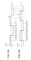
2相駆動の場合においても、その構成は図2に示した場合と基本的には同一であり、励磁相Aと励磁相Bとに90度位相のずれた2相の電流を流してそれぞれ電磁石3、4を励磁する。ここで、励磁相A、Bに流す電流はレベル一定の定電流であるとする。すなわち、図11Aおよび図11Bに示すように励磁相A、Bに流す電流α、βは位相が90度ずれた矩形波である。
【0064】
以下において、励磁電流を図11Aおよび図11Bに示すごとく、位相を45度ずつに区切った各電流区間a、b、c、d、e、f、g、hに対して、図8A、図8B、図8C、図9A、図9B、図9C、図10A、図10Bがそれぞれ対応し、図8A、図8B、図8C、図9A、図9B、図9C、図10A、図10Bに基づいて説明する。
【0065】
電流区間aにおいて、図8Aに示すごとく、励磁相Aに通電されることによって電磁石鉄心3−1が磁化されて磁界φcaが生成され、励磁相Bに通電されることによって電磁石鉄心4−1が磁化されて磁界φcbが生成される。
【0066】
したがって、電磁石鉄心3−1の一方の脚にはN極が生成され、電磁石鉄心3−1の他方の脚にはS極が生成されて、永久磁石2−0と永久磁石2−1との間の界磁ヨーク部分と電磁石鉄心3−1の一方の脚との間および永久磁石2−1と永久磁石2−2との間の界磁ヨーク部分と電磁石鉄心3−1の他方の脚との間には吸引力が発生し、永久磁石2−1と永久磁石2−2との間の界磁ヨーク部分と電磁石鉄心3−1の一方の脚との間および永久磁石2−2と永久磁石2−3との間の界磁ヨーク部分と電磁石鉄心3−1の他方の脚との間には反発力が発生する。
【0067】
同時に、電磁石鉄心4−1の一方の脚にはN極が生成され、電磁石鉄心4−1の他方の脚にはS極が生成されて、永久磁石2−3と永久磁石2−4との間の界磁ヨーク部分と電磁石鉄心4−1の一方の脚との間および永久磁石2−4と永久磁石2−5との間の界磁ヨーク部分と電磁石鉄心4−1の他方の脚との間には反発力が発生する。
【0068】
この結果、界磁ヨーク1が移動し、図8Bの状態となる。
【0069】
電流区間bにおいて、図8Bに示すごとく、励磁相Aに通電されることによって電磁石鉄心3−1が磁化されて磁界φcaが生成され、励磁相Bに通電されることによって電磁石鉄心4−1が磁化されて磁界φcbが生成される。
【0070】
したがって、電磁石鉄心3−1の一方の脚にはN極が生成され、電磁石鉄心3−1の他方の脚にはS極が生成されて、永久磁石2−0と永久磁石2−1との間の界磁ヨーク部分と電磁石鉄心3−1の一方の脚との間および永久磁石2−1と永久磁石2−2との間の界磁ヨーク部分と電磁石鉄心3−1の他方の脚との間には吸引力が発生し、永久磁石2−1と永久磁石2−2との間の界磁ヨーク部分と電磁石鉄心3−1の一方の脚との間および永久磁石2−2と永久磁石2−3との間の界磁ヨーク部分と電磁石鉄心3−1の他方の脚との間には反発力が発生する。
【0071】
同時に、電磁石鉄心4−1の一方の脚にはN極が生成され、電磁石鉄心4−1の他方の脚にはS極が生成されて、永久磁石2−2と永久磁石2−3との間の界磁ヨーク部分と電磁石鉄心4−1の一方の脚との間および永久磁石2−3と永久磁石2−4との間の界磁ヨーク部分と電磁石鉄心4−1の他方の脚との間には吸引力が発生し、永久磁石2−3と永久磁石2−4との間の界磁ヨーク部分と電磁石鉄心4−1の一方の脚との間および永久磁石2−4と永久磁石2−5との間の界磁ヨーク部分と電磁石鉄心4−1の他方の脚との間には反発力が発生する。
【0072】
この結果、界磁ヨーク1は図8Cにおいて一旦停止状態となる。界磁ヨーク1は図8Aの状態から図8Bの状態を経て、図8Cの状態へと右側方向にτe/mにて定まる1ステップ幅だけ移動する。
【0073】
電流区間cにおいて、図8Cに示すごとく、励磁相Aは図8Aの場合に対して逆方向に通電されることによって電磁石3の鉄心3−1が逆方向に磁化されて磁界φcaが生成され、励磁相Bに通電されることによって電磁石鉄心4−1が磁化されて磁界φcbが生成される。
【0074】
したがって、電磁石鉄心3−1の一方の脚にはS極が生成され、電磁石鉄心3−1の他方の脚にはN極が生成されて、永久磁石2−0と永久磁石2−1との間の界磁ヨーク部分と電磁石鉄心3−1の一方の脚との間および永久磁石2−1と永久磁石2−2との間の界磁ヨーク部分と電磁石鉄心3−1の他方の脚との間には反発力が発生する。
【0075】
同時に、電磁石鉄心4−1の一方の脚にはN極が生成され、電磁石鉄心4−1の他方の脚にはS極が生成されて、永久磁石2−2と永久磁石2−3との間の界磁ヨーク部分と電磁石鉄心4−1の一方の脚との間および永久磁石2−3と永久磁石2−4との間の界磁ヨーク部分と電磁石鉄心4−1の他方の脚との間には吸引力が発生し、永久磁石2−3と永久磁石2−4との間の界磁ヨーク部分と電磁石鉄心4−1の一方の脚との間および永久磁石2−4と永久磁石2−5との間の界磁ヨーク部分と電磁石鉄心4−1の他方の脚との間には反発力が発生する。
【0076】
この結果、界磁ヨーク1が移動し、図9Aの状態となる。
【0077】
電流区間dにおいて、図9Aに示すごとく、励磁相Aは図8Aの場合に対して逆方向に通電されることによって電磁石鉄心3−1が磁化されて磁界φcaが生成され、励磁相Bに通電されることによって電磁石鉄心4−1が磁化されて磁界φcbが生成される。
【0078】
したがって、電磁石鉄心3−1の一方の脚にはS極が生成され、電磁石鉄心3−1の他方の脚にはN極が生成されて、永久磁石2−(−1)と永久磁石2−0との間の界磁ヨーク部分と電磁石鉄心3−1の一方の脚との間および永久磁石2−0と永久磁石2−1との間の界磁ヨーク部分と電磁石鉄心3−1の他方の脚との間には吸引力が発生し、永久磁石2−0と永久磁石2−1との間の界磁ヨーク部分と電磁石鉄心3−1の一方の脚との間および永久磁石2−1と永久磁石2−2との間の界磁ヨーク部分と電磁石鉄心3−1の他方の脚との間には反発力が発生する。
【0079】
同時に、電磁石鉄心4−1の一方の脚にはN極が生成され、電磁石鉄心4−1の他方の脚にはS極が生成されて、永久磁石2−2と永久磁石2−3との間の界磁ヨーク部分と電磁石鉄心4−1の一方の脚との間および永久磁石2−3と永久磁石2−4との間の界磁ヨーク部分と電磁石鉄心4−1の他方の脚との間には吸引力が発生し、永久磁石2−3と永久磁石2−4との間の界磁ヨーク部分と電磁石鉄心4−1の一方の脚との間および永久磁石2−4と永久磁石2−5との間の界磁ヨーク部分と電磁石鉄心4−1の他方の脚との間には反発力が発生する。
【0080】
この結果、界磁ヨーク1が移動し、図9Bにおいて一旦停止状態となる。界磁ヨーク1は図8Cの状態から図9Aの状態を経て図9Bの状態へと右側方向にτe/mにて定まる1ステップ幅だけ移動する。
【0081】
電流区間eにおいて、図9Bに示すごとく、励磁相Aに図8Aの場合に対して逆方向に通電されることによって電磁石鉄心3−1が磁化されて磁界φcaが生成され、励磁相Bに図8Aの場合に対して逆方向通電されることによって電磁石鉄心4−1が磁化されて磁界φcbが生成される。
【0082】
したがって、電磁石鉄心3−1の一方の脚にはS極が生成され、電磁石鉄心3−1の他方の脚にはN極が生成されて、永久磁石2−(−1)と永久磁石2−0との間の界磁ヨーク部分と電磁石鉄心3−1の一方の脚との間および永久磁石2−0と永久磁石2−1との間の界磁ヨーク部分と電磁石鉄心3−1の他方の脚との間には吸引力が発生し、永久磁石2−0と永久磁石2−1との間の界磁ヨーク部分と電磁石鉄心3−1の一方の脚との間および永久磁石2−1と永久磁石2−2との間の界磁ヨーク部分と電磁石鉄心3−1の他方の脚との間には反発力が発生する。
【0083】
同時に、電磁石鉄心4−1の一方の脚にはS極が生成され、電磁石鉄心4−1の他方の脚にはN極が生成されて、永久磁石2−2と永久磁石2−3との間の界磁ヨーク部分と電磁石鉄心4−1の一方の脚との間および永久磁石2−3と永久磁石2−4との間の界磁ヨーク部分と電磁石鉄心4−1の他方の脚との間には反発力が発生する。
【0084】
この結果、界磁ヨーク1が移動し、図9Cの状態となる。
【0085】
電流区間f、gおよびhについても、図9C、図10A、図10Bに示すごとくであって、この場合の作用も電流区間a、b、c、dおよびeにおける作用から容易に類推することができよう。
【0086】
図8A〜図10Bに示した2相励磁による駆動の場合に、各相に発生する推力は図12に示すごとくである。
【0087】
以上からも明らかな如く、本発明の実施の一形態にかかるリニアモータ10では、図2A〜図3Bおよび図8A〜図10Bのように、1相励磁および2相励磁によって駆動することができる。
【0088】
本発明の実施の一形態にかかるリニアモータ10の変位に対する推力特性とバリアブルリラクタンスリニアモータの変位に対する推力特性とを比較した場合、図13に示す如くであって、本発明の実施の一形態にかかるリニアモータ10の変位に対する推力特性が格段に良好であった。図13において、実線は本発明の実施の一形態にかかるリニアモータ10の変位に対する推力特性を示し、破線はバリアブルリラクタンスリニアモータの変位に対する推力特性を示している。
【0089】
界磁ヨーク1に埋め込まれる永久磁石の埋め込み長さ(永久磁石は界磁ヨーク1の表面と同一の表面を形成するように埋め込まれているため、永久磁石の埋め込み長さは埋め込み深さでもあるが、以下、永久磁石の埋め込み長さと記す)を変化させた場合における本発明の実施の一形態にかかるリニアモータ10において、変位に対する推力特性は図14に示す如くであった。図14において、実線は界磁ヨーク1に埋め込まれる永久磁石の埋め込み長さが例えば2.5mmの場合を示し、破線は界磁ヨーク1に埋め込まれる永久磁石の埋め込み長さが例えば1.0mmの場合を示している。しかし、永久磁石の埋め込み長さが3mm以上で飽和する傾向を示した。
【0090】
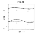
界磁ヨーク1に埋め込まれる永久磁石の埋め込み長さを変化させた場合における本発明の実施の一形態にかかるリニアモータ10において、変位に対する垂直力特性は図15に示す如くであった。図15において、実線aは界磁ヨーク1に埋め込まれる永久磁石の埋め込み長さが例えば2.5mmの場合を示し、実線cは例えば1.0mmの場合を示している。それぞれに対する図15における破線b、dはコイルに通電していないときの垂直力を示している。
【0091】
また、本発明の実施の一形態にかかるリニアモータ10において、界磁ヨーク1に埋め込まれる永久磁石の埋め込み長さを変化させた場合における垂直力特性は図16に示す如くであった。
【0092】
また、本発明の実施の一形態にかかるリニアモータ10において、界磁ヨーク1に埋め込まれる永久磁石の埋め込み長さを変化させた場合における推力特性およびディテント力特性は図17に示す如くであった。図17において実線は推力特性を示し、破線はディテント力特性を示す。
【0093】
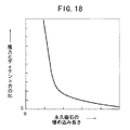
さらにまた、本発明の実施の一形態にかかるリニアモータ10において、界磁ヨーク1に埋め込まれる永久磁石の埋め込み長さを変化させた場合における推力/ディテント力の比は図18に示す如くであった。
【0094】
また、本発明の実施の一形態にかかるリニアモータ10において、界磁ヨーク1に埋め込まれる永久磁石の埋め込み長さを変化させた場合における推力/垂直力の比は図19に示す如くであった。
【0095】
上記の特性から、界磁ヨーク1に埋め込まれる永久磁石の埋め込み長さには、界磁ヨーク1の材質、永久磁石の材質、電磁石鉄心の材質などの関係で定まる適当な長さが存在する。
【0096】
上記した本発明の実施の一形態にかかるリニアモータ10における電磁石3、4の電磁石鉄心3−1、4−1は、図2A〜図3B、図8A〜図10Bにおいて、断面U字状の場合を例示したが、電磁石鉄心3−1(4−1)に代わって断面E字状の電磁石鉄心3−5(4−5)、すなわち3脚状に形成し、その中央の脚3−6(4−6)にコイル3−2(4−2)を巻き回した構成であってもよい。
【0097】
この場合の構成例は、永久磁石の一部と共に示せば図20〜図22に示す如くである。
【0098】
図20の(A)の場合は電磁石鉄心3−5(4−5)の両外側の脚3−7(4−7)、3−8(4−8)、中央の脚3−6(4−6)のそれぞれの位置が永久磁石の位置にほぼ対向し、コイル3−2(4−2)に通電していない状態を示している。
【0099】
図20の(B)は図20の(A)においてコイル3−2(4−2)に通電したときの状態を示し、通電による磁化によって電磁石鉄心3−5(4−5)の両外側の脚3−7(4−7)、3−8(4−8)にS極が生成され、中央の脚3−6(4−6)にはN極が生成されて、永久磁石間における界磁ヨークとの間で矢印で示した吸引力と反発力が生ずる。
【0100】
図21の(A)の場合は電磁石鉄心3−5(4−5)の両外側の脚3−7(4−7)、3−8(4−8)、中央の脚3−6(4−6)のそれぞれが隣り合う永久磁石間の界磁ヨーク部分にほぼ対向し、コイル3−2(4−2)に通電していない状態を示している。
【0101】
図21の(B)は図21の(A)においてコイル3−2(4−2)に通電したときの状態を示し、通電による磁化によって電磁石鉄心3−5(4−5)の両外側の脚3−7(4−7)、3−8(4−8)にS極が生成され、中央の脚3−6(4−6)にはN極が生成されて、永久磁石間の界磁ヨーク1との間で矢印で示した反発力のみが生ずる。
【0102】
図22は断面E字状の電磁石鉄心の変形例を示している。
【0103】
図22に示す電磁石鉄心の場合は、対をなす一対の脚3−11と3−12と、対をなす一対の脚3−13と脚3−14とを有し、ヨークにて連結されていて、脚3−11と脚3−12とはそれぞれ永久磁石のピッチにほぼ等しい極ピッチを有し、脚3−13と脚3−14とはそれぞれ永久磁石のピッチにほぼ等しい極ピッチを有し、脚3−12と脚3−13との極ピッチは永久磁石の2倍のピッチにほぼ等しい間隔に構成してある。
【0104】
この図22に示すように構成することにより、通電にて電磁石鉄心の脚と界磁ヨーク1との間で吸引力と反発力が生じ、極ピッチに対してコイルの体積を大きくすることができて、大きな推力を得ることができる。
【0105】
次に、3相駆動用の場合について説明する。
【0106】
図23は本発明の実施の一形態にかかるリニアモータ10を3相駆動に対応させた場合の構成を示す模式説明図である。
【0107】
この場合は、上記した(5)式および(6)式にしたがって、永久磁石2−1、2−2、2−3、…をピッチτpで界磁ヨーク1に埋め込み、電磁石の極のピッチをτe、電磁石間のピッチをτg、電磁石鉄心の脚の幅をτe/2として、互いにτd=5τe/6の間隔を隔てて設けた3つの電磁石3、4、5を備えて、電磁石3、4、5によって励磁相A、励磁相B、励磁相Cを構成し、励磁相A、励磁相B、励磁相Cを3相駆動する。
【0108】
図23において、符号3−1、4−1、5−1は電磁石鉄心を示し、符号3−2、4−2、5−2はコイルを示している。
【0109】
この3相駆動の場合の作用も、2相駆動の場合と同様であって、大きな推力が得られる。
【0110】
次に、5相駆動用の場合について説明する。
【0111】
図24は本発明の実施の一形態にかかるリニアモータ10を5相駆動に対応させた場合の構成を示す模式説明図である。
【0112】
この場合は、上記した(5)式および(6)式にしたがって、永久磁石2−1、2−2、2−3、…をピッチτpで界磁ヨーク1に埋め込み、電磁石の極のピッチをτe、電磁石間のピッチをτg、電磁石鉄心の脚の幅をτe/2として、互いにτd=7τe/10の間隔を隔てて設けた5つの電磁石3、4、5、6、7を備えて、電磁石3、4、5、6、7によって励磁相A、励磁相B、励磁相C、励磁相D、励磁相Eを構成し、5相駆動する。
【0113】
図24において、符号3−1、4−1、5−1、6−1、7−1は電磁石鉄心を示し、符号3−2、4−2、5−2、6−2、7−2はコイルを示している。
【0114】
この5相駆動の場合の作用も、2相駆動、3相駆動の場合と同様であって、大きな推力が得られる。
【0115】
【発明の効果】
以上説明したように、本発明にかかるリニアモータによれば、磁性体からなる界磁ヨークに長さ方向に所定ピッチで隣り合う極性が互いに逆になるように複数の永久磁石を埋め込み、予め定めた間隔の極ピッチを有する複数の電磁石を界磁ヨークの長さ方向に沿って所定ピッチで設けると共に、界磁ヨークに対向して所定ギャップ隔てて設けて、電磁石を順次励磁することによって、界磁ヨークに埋め込まれた永久磁石の磁極と永久磁石間の界磁ヨーク部分に形成される磁極と磁化により電磁石に形成される磁極との間の極性に基づく吸引力と反発力とが生じて、界磁ヨークと電磁石との間に推力が発生し、界磁ヨークと電磁石の一方が駆動される。この場合の構成は簡単であるにもかかわらず、大きな推力を得ることができる。
【図面の簡単な説明】
【図1】本発明の実施の一形態にかかるリニアモータの構成図である。
【図2】本発明の実施の一形態にかかるリニアモータの構成を示す模式説明図である。
【図3】本発明の実施の一形態にかかるリニアモータの構成を示す模式説明図である。
【図4】本発明の実施の一形態にかかるリニアモータにおける永久磁石の相互の位置関係と、電磁石の位置関係とを示す模式説明図である。
【図5】本発明の実施の一形態にかかるリニアモータにおける変位に対する推力特性図である。
【図6】本発明の実施の一形態にかかるリニアモータの推力特性と、従来のリニアモータの推力特性とを比較した模式特性図である。
【図7】本発明の実施の一形態にかかるリニアモータにおける電磁石の他の構成を示す模式図である。
【図8】本発明の実施の一形態にかかるリニアモータを2相励磁した場合の説明に供する模式説明図である。
【図9】本発明の実施の一形態にかかるリニアモータを2相励磁した場合の説明に供する模式説明図である。
【図10】本発明の実施の一形態にかかるリニアモータを2相励磁した場合の説明に供する模式説明図である。
【図11】本発明の実施の一形態にかかるリニアモータを2相励磁する場合の励磁電流の模式波形図である。
【図12】本発明の実施の一形態にかかるリニアモータを2相励磁した場合において各相に発生する推力を示す推力特性図である。
【図13】本発明の実施の一形態にかかるリニアモータにおける変位に対する推力および従来のバリアブルリラクタンスリニアモータにおける変位に対する推力を示す推力特性図である。
【図14】永久磁石の埋め込み長さを変化させたときにおける本発明の実施の一形態にかかるリニアモータにおける変位に対する推力を示す推力特性図である。
【図15】永久磁石の埋め込み長さを変化させたときにおける本発明の実施の一形態にかかるリニアモータにおける変位に対する垂直力を示す垂直力特性図である。
【図16】本発明の実施の一形態にかかるリニアモータにおける永久磁石の埋め込み長さの変化に対する垂直力を示す垂直力特性図である。
【図17】本発明の実施の一形態にかかるリニアモータにおける永久磁石の埋め込み長さの変化に対する推力を示す推力特性図である。
【図18】本発明の実施の一形態にかかるリニアモータにおける永久磁石の埋め込み長さの変化に対する推力/ディテント力の比を示す特性図である。
【図19】本発明の実施の一形態にかかるリニアモータにおける永久磁石の埋め込み長さの変化に対する推力/垂直力の比を示す特性図である。
【図20】本発明の実施の一形態にかかるリニアモータにおける断面E字状の電磁石鉄心を用いた電磁石の構成を示す模式図である。
【図21】本発明の実施の一形態にかかるリニアモータにおける断面E字状の電磁石鉄心を用いた電磁石の構成を示す模式図である。
【図22】本発明の実施の一形態にかかるリニアモータにおける断面E字状の電磁石鉄心の変形例を用いた電磁石の構成を示す模式図である。
【図23】本発明の実施の一形態にかかるリニアモータを3相駆動に対応させた場合の構成を示す模式説明図である。
【図24】本発明の実施の一形態にかかるリニアモータを5相駆動に対応させた場合の構成を示す模式説明図である。
【符号の説明】
1…界磁ヨーク
2−0〜2−8…永久磁石
2〜7…電磁石
3−1、3−5、4−1、4−5、5−1、6−1、7−1…電磁石鉄心
3−2、4−2、5−2、6−2、7−2…コイル
3−6〜3−8、3−11〜3−14、4−6〜4−8…脚
10…リニアモータ[0001]
BACKGROUND OF THE INVENTION
The present invention relates to a linear motor in which a permanent magnet is embedded in a field yoke.
[0002]
[Prior art]
Many linear motors or pulse motors provided with permanent magnets have been proposed. When attention is paid to the method of providing permanent magnets, there are the following ones.
[0003]
A variable reluctance linear pulse motor provided with a permanent magnet joined to the iron core in the vicinity of the upper part of the iron core provided with the exciting coil and provided with a magnetic pole plate for sandwiching the permanent magnet with the iron core. 63-294252). There are also permanent magnets that are divided and arranged (Japanese Patent Laid-Open Nos. 2-307356 and 2-33250).
[0004]
However, in the linear pulse motor disclosed in Japanese Patent Laid-Open No. 63-294252, Japanese Patent Laid-Open No. 2-307356 and Japanese Patent Laid-Open No. 2-33250, the permanent magnet is provided on the upper side of the excitation side, so that the iron core cannot be reduced in size. There is a problem.
[0005]
The first and second moving elements, which are respectively arranged on the upper and lower surfaces of the stator and mechanically fixed to each other, are each formed of a U-shaped core, and the core is divided into two, and a permanent magnet is interposed between one and the other. There is a linear pulse motor (Japanese Patent Laid-Open No. 64-47258), which is arranged so that a magnetic flux flows through the core and an excitation winding is applied to the core.
[0006]
However, the linear pulse motor disclosed in Japanese Patent Application Laid-Open No. 64-47258 has a problem that the permanent magnet is provided on the excitation side and the excitation side cannot be reduced in size.
[0007]
In addition, a permanent magnet is provided on the iron core teeth on the rotor excitation side, a linear pulse motor provided with a slit in the non-magnetized portion, a permanent magnet is provided on the iron core teeth of the stator, and a slit is provided in the non-magnetized portion. There is a linear pulse motor (Japanese Patent Laid-Open No. 1-229845) provided with a slit plate.
[0008]
However, the linear pulse motor disclosed in JP-A-1-298945 has a problem that the iron core including the slit plate cannot be reduced in size.
[0009]
In addition, a permanent magnet that generates a magnetomotive force in a direction perpendicular to the direction of the magnetomotive force by the electromagnet at the tip of the magnetic pole constituting the electromagnet of the moving element, or a magnetomotive force that is generated in a direction parallel to the direction of the magnetomotive force by the electromagnet There is a linear pulse motor (Japanese Patent Laid-Open No. 2-114852) provided with a permanent magnet.
[0010]
However, the linear pulse motor disclosed in Japanese Patent Application Laid-Open No. 2-114852 has a problem that the electromagnet cannot be reduced in size because a permanent magnet is provided at the tip of the magnetic pole.
[0011]
In addition, a magnetic block having small teeth arranged in the direction of the outer peripheral axis and a permanent magnet that magnetizes the magnetic block to a predetermined magnetic pole are magnetized by the permanent magnet into magnets having different polarities, and one of the magnetic pole blocks A linear pulse motor in which when the tooth tip faces the tooth tip of the salient pole of the stator, the tooth tip of the other magnetic pole block faces the tooth bottom of the salient pole of the stator (Japanese Patent Laid-Open No. 6-197517) There is.
[0012]
However, the linear pulse motor disclosed in Japanese Patent Laid-Open No. Hei 6-197517 has a problem that it cannot be miniaturized because of the presence of the magnetic pole block.
[0013]
Further, in a movable body having a movable body iron core in which a plurality of movable body small teeth are formed at an equal pitch in the axial direction facing the small stator teeth on the outer peripheral surface, between the movable body shaft and the movable body core And a linear pulse motor provided with a cylindrical member made of a non-magnetic material (JP-A-7-170719, JP-A-7-170719) flat No. 8-9623).
[0014]
However, Japanese Patent Laid-Open No. 7-170719 and Japanese Patent Laid-Open No. 7-170719. flat The linear pulse motor disclosed in Japanese Patent No. 8-9623 has a problem that it cannot be miniaturized due to the presence of a cylindrical member between the axis of the moving element and the moving element iron core.
[0015]
In addition, a permanent magnet is provided for magnetizing the rotor cores arranged at predetermined intervals in the axial direction to the north and south poles, the rotor shaft is made of a magnetic material or a non-magnetic material, and the permanent magnet is a cylinder. There is a linear pulse motor (Japanese Patent Laid-Open No. 7-288969) that is formed in a shape and disposed between a moving iron core and a moving element shaft.
[0016]
However, the linear pulse motor disclosed in Japanese Patent Application Laid-Open No. 7-288969 has a problem that it cannot be miniaturized due to the presence of a permanent magnet.
[0017]
Also, there is a linear pulse motor (Japanese Patent Laid-Open No. 8-163857) in which a permanent magnet magnetized in the axial direction is interposed between moving element cores arranged at predetermined intervals in the axial direction.
[0018]
However, the linear pulse motor disclosed in JP-A-8-163857 has a problem that it cannot be miniaturized because a permanent magnet is present.
[0019]
In addition, a plurality of exciting unit groups that function as a stator and are arranged at intervals of 1/8 pitch are provided with a predetermined gap, and movable portions in which teeth made of permanent magnets and magnetic bodies are alternately arranged at a predetermined pitch. A linear pulse comprising a magnetic pole unit as a child, and one excitation unit having magnetic poles arranged so as to sandwich the magnetic pole unit from both sides, a magnetic member connecting the magnetic poles, and an armature coil wound around the magnetic member There is a motor (Japanese Patent Laid-Open No. 10-327571).
[0020]
However, the linear pulse motor disclosed in Japanese Patent Application Laid-Open No. 10-327571 has a problem that it cannot be miniaturized because a permanent magnet exists.
[0021]
In addition, a permanent magnet is provided in a mover in which a plurality of mover small teeth are formed, and the mover small teeth are arranged at intervals of 1/2 the stator small tooth pitch. A pair of mover cores is formed by sandwiching a permanent magnet magnetized in the axial direction between the teeth and the small teeth, and a linear pulse magnetically insulated between the pairs via a gap or a non-magnetic material There is a motor (Japanese Patent Laid-Open No. 11-41905).
[0022]
However, the linear pulse motor disclosed in Japanese Patent Application Laid-Open No. 11-41905 has a problem that the slider cannot be reduced in size.
[0023]
[Problems to be solved by the invention]
However, the linear pulse motor using a permanent magnet has a problem that it is difficult to reduce the size and does not have sufficient thrust.
[0024]
An object of the present invention is to provide a linear motor that has a simple structure and can be downsized and has sufficient thrust.
[0025]
[Means for Solving the Problems]
A linear motor according to the present invention includes a plurality of permanent magnets embedded in a field yoke made of a magnetic material at a predetermined pitch in the length direction,
A plurality of electromagnets having a pole pitch of a predetermined interval, provided at a predetermined pitch along the length direction of the field yoke, and provided at a predetermined gap facing the field yoke;
Adjacent permanent magnets are magnetized in opposite directions.
[0026]
According to the linear motor of the present invention, between the magnetic pole of the permanent magnet embedded in the field yoke at a predetermined pitch, the magnetic pole formed in the field yoke portion between the permanent magnets, and the magnetic pole formed in the electromagnet by magnetization. A thrust is generated between the field yoke and the electromagnet by the attractive force and the repulsive force based on the polarity, and one of the field yoke and the electromagnet side is relatively driven.
[0027]
In the linear motor of the present invention, τp is the pitch between the permanent magnets embedded in the field yoke, τe is the pole pitch between the electromagnets, τg is the pitch between the electromagnets, m is the number of excitation phases, and n is 0, 1 When 2, 3, ..., s is 1, 2, 3, ...
τe≈ (2n + 1) τp (3)
τg = (2s + 1 / m) τe (4)
It is characterized by.
[0028]
According to the linear motor of the present invention, the permanent magnet is embedded in the field yoke at a pitch τp≈ (2n + 1) / τe, and the pitch τg between the electromagnets is formed at a position of τg = (2s + 1 / m) τe. In addition, the field yoke or the electromagnet is driven in one direction with a step width τe / m.
[0029]
In the linear motor of the present invention, the iron core of the electromagnet has two legs for generating magnetic poles of different polarities connected by a yoke, and a coil is wound around a yoke portion connecting the legs. And
[0030]
According to the linear motor of the present invention, each leg can be magnetized to have a different polarity by energizing a coil wound around a yoke portion connecting the legs.
[0031]
In the linear motor of the present invention, the iron core of the electromagnet has two legs that are connected by a yoke to generate magnetic poles of different polarities, and constitutes a differential coil by winding each leg in the reverse winding direction, Each leg is magnetized to a different polarity by energizing the differential coil.
[0032]
According to the linear motor of the present invention, each leg can be magnetized to a different polarity by energizing the differential coil.
[0033]
In the linear motor of the present invention, the electromagnet has three legs and has a coil wound around the central leg, and the outer legs sandwiching the central leg are magnetized to different polarities by energizing the coil. It is characterized by that.
[0034]
According to the linear motor of the present invention, each of the outer legs of the electromagnet can be magnetized in different polarities by energizing the coil wound around the center leg of the three legs.
[0035]
DETAILED DESCRIPTION OF THE INVENTION
An embodiment of a linear motor according to the present invention will be described.
[0036]
FIG. 1 is a configuration diagram of a
[0037]
The
[0038]
2 and 3 are schematic explanatory views showing the configuration of the
[0039]
Permanent magnets 2-0, 2-1, 2-2,..., 2-, which are formed in a predetermined interval, for example, in a
[0040]
On the other hand, it is wound around an electromagnet core 3-1 and an electromagnet core 3-1, which are made of a laminated silicon steel sheet having a U-shaped cross-section with a gap of a predetermined interval facing the
[0041]
Here, FIG. 2 and FIG. 3 exemplify the case of providing two excitation phases and one-phase excitation. Hereinafter, the
[0042]
Here, as shown in FIG. 4, the pitch of the permanent magnets 2-0, 2-1, 2-2,... Embedded in the
τe≈ (2n + 1) τp (5)
There is a relationship.
[0043]
Here, n = 0, 1, 2, 3,..., Is expressed as ≈ because it may be slightly shifted in order to suppress fluctuations in thrust.
[0044]
The pitch τg between the
τg = (2s + 1 / m) τe (6)
It is set to.
[0045]
Here, s = 1, 2, 3,..., And m = the number of excitation phases.
[0046]
The interval τd between the
[0047]
The distance τd between the
[0048]
As shown in FIG. 2A, in the initial position where the
[0049]
In this state, a magnetic field φp is generated in the direction of the south pole of the permanent magnet 2-1 from the field yoke portion between the permanent magnet 2-1 and the permanent magnet 2-2 through one leg of the electromagnet core 3-1. The magnetic field φp is generated in the direction of the south pole of the permanent magnet 2-2 from the field yoke portion between the permanent magnet 2-1 and the permanent magnet 2-2 through the other leg of the electromagnet core 3-1. A magnetic field φp is generated through the electromagnet core 4-1 in the direction of the south pole of the permanent magnet 2-4 from the field yoke portion between the 2-3 and the permanent magnet 2-4.
[0050]
From the state of FIG. 2A at the initial position of the excitation phase A, the coil 3-2, that is, the excitation phase A is energized in the direction shown in FIG. 2B. By this energization, the
[0051]
As shown in FIG. 2C, the
[0052]
Next to the initial position of excitation phase B in FIG. 3A, excitation phase B is excited. From the state in which the excitation phase B is at the initial position, the coil 4-2, that is, the excitation phase B is energized in the direction shown in FIG. 3B. By this energization, a magnetic field φc is generated counterclockwise in the electromagnet core 4-1, and one leg of the electromagnet core 4-1, and the field yoke portion between the permanent magnet 2-2 and the permanent magnet 2-3. The attraction force works between the other leg of the electromagnet core 4-1 and the field yoke portion between the permanent magnet 2-3 and the permanent magnet 2-4 to generate thrust. Subsequently, the
[0053]
Thus, thrust is generated in the
[0054]
At this time, the thrust characteristic with respect to the displacement generated in the
[0055]
FIG. 6 shows the relationship between the magnetomotive force and the thrust generated by the electromagnet when the
[0056]
As described above, according to the
(A) The direction of thrust generated in the legs of the electromagnet cores 3-1 and 4-1 of the
[0057]
(B) By embedding permanent magnets in the
[0058]
(C) Since the
[0059]
In addition, although the case where the
[0060]
Further, instead of the configuration shown in FIG. 4, the coils 3-2a (4-2a) are wound around one leg of the electromagnet core 3-1 (4-1) as shown in FIG. The coil 3-2b (4-2b) is wound around the other leg of the electromagnet core 3-1 (4-1) in the other direction, and both coils 3-2a (4-2a) and 3-2b (4- 2b) may be connected in series to form a differential coil 3-2c (4-2c). By energizing the differential coil 3-2c (4-2c), the polarity of one leg of the electromagnetic iron core 3-1 (4-1) is different from that of the other leg of the electromagnetic iron core 3-1 (4-1). Magnetized.
[0061]
Next, the case of two-phase driving will be described with reference to FIGS.
[0062]
8-10, the arrow described in the gap between the
[0063]
Even in the case of two-phase driving, the configuration is basically the same as that shown in FIG. 2, and a two-phase current that is 90 degrees out of phase is passed through excitation phase A and excitation phase B to cause electromagnets respectively. 3 and 4 are excited. Here, it is assumed that the current flowing in the excitation phases A and B is a constant current with a constant level. That is, as shown in FIGS. 11A and 11B, the currents α and β flowing in the excitation phases A and B are rectangular waves whose phases are shifted by 90 degrees.
[0064]
In the following, as shown in FIGS. 11A and 11B, the excitation current is shown in FIGS. 8A and 8B with respect to the current sections a, b, c, d, e, f, g, and h divided by 45 degrees. 8C, FIG. 9A, FIG. 9B, FIG. 9C, FIG. 10A, and FIG. 10B correspond to each other, and are described based on FIG. 8A, FIG. 8B, FIG. 8C, FIG. To do.
[0065]
In the current section a, as shown in FIG. 8A, when the excitation phase A is energized, the electromagnet core 3-1 is magnetized to generate the magnetic field φca, and when the excitation phase B is energized, the electromagnet core 4-1 is Magnetized to generate a magnetic field φcb.
[0066]
Therefore, an N pole is generated on one leg of the electromagnet core 3-1, and an S pole is generated on the other leg of the electromagnet core 3-1, and the permanent magnet 2-0 and the permanent magnet 2-1 Between the field yoke portion between and the one leg of the electromagnet core 3-1, and between the field yoke portion between the permanent magnet 2-1 and the permanent magnet 2-2 and the other leg of the electromagnet core 3-1. An attraction force is generated between the permanent magnet 2-1 and the permanent magnet 2-2, between the field yoke portion and one leg of the electromagnet core 3-1, and between the permanent magnet 2-2 and the permanent magnet 2-2. A repulsive force is generated between the field yoke portion between the magnet 2-3 and the other leg of the electromagnet core 3-1.
[0067]
At the same time, an N pole is generated on one leg of the electromagnet core 4-1, and an S pole is generated on the other leg of the electromagnet core 4-1, so that the permanent magnet 2-3 and the permanent magnet 2-4 Between the field yoke portion between and one leg of the electromagnet core 4-1, and between the field yoke portion between the permanent magnet 2-4 and the permanent magnet 2-5 and the other leg of the electromagnet core 4-1. A repulsive force is generated between the two.
[0068]
As a result, the
[0069]
In the current section b, as shown in FIG. 8B, when the excitation phase A is energized, the electromagnet core 3-1 is magnetized to generate the magnetic field φca, and when the excitation phase B is energized, the electromagnet core 4-1 is Magnetized to generate a magnetic field φcb.
[0070]
Therefore, an N pole is generated on one leg of the electromagnet core 3-1, and an S pole is generated on the other leg of the electromagnet core 3-1, and the permanent magnet 2-0 and the permanent magnet 2-1 Between the field yoke portion between and the one leg of the electromagnet core 3-1, and between the field yoke portion between the permanent magnet 2-1 and the permanent magnet 2-2 and the other leg of the electromagnet core 3-1. An attraction force is generated between the permanent magnet 2-1 and the permanent magnet 2-2, between the field yoke portion and one leg of the electromagnet core 3-1, and between the permanent magnet 2-2 and the permanent magnet 2-2. A repulsive force is generated between the field yoke portion between the magnet 2-3 and the other leg of the electromagnet core 3-1.
[0071]
At the same time, an N pole is generated on one leg of the electromagnet core 4-1, and an S pole is generated on the other leg of the electromagnet core 4-1, and the permanent magnet 2-2 and the permanent magnet 2-3 are connected to each other. Between the field yoke portion between and one leg of the electromagnet core 4-1, and between the permanent magnet 2-3 and the permanent magnet 2-4, and the other leg of the electromagnet core 4-1. An attraction force is generated between the permanent magnet 2-3 and the permanent magnet 2-4, between the field yoke portion and one leg of the electromagnet core 4-1, and between the permanent magnet 2-4 and the permanent magnet. A repulsive force is generated between the field yoke portion between the magnet 2-5 and the other leg of the electromagnet core 4-1.
[0072]
As a result, the
[0073]
In the current section c, as shown in FIG. 8C, the excitation phase A is energized in the reverse direction with respect to the case of FIG. When the excitation phase B is energized, the electromagnet core 4-1 is magnetized and a magnetic field φcb is generated.
[0074]
Therefore, an S pole is generated on one leg of the electromagnet core 3-1, and an N pole is generated on the other leg of the electromagnet core 3-1, and the permanent magnet 2-0 and the permanent magnet 2-1 Between the field yoke portion between and the one leg of the electromagnet core 3-1, and between the field yoke portion between the permanent magnet 2-1 and the permanent magnet 2-2 and the other leg of the electromagnet core 3-1. A repulsive force is generated between the two.
[0075]
At the same time, an N pole is generated on one leg of the electromagnet core 4-1, and an S pole is generated on the other leg of the electromagnet core 4-1, and the permanent magnet 2-2 and the permanent magnet 2-3 are connected to each other. Between the field yoke portion between and one leg of the electromagnet core 4-1, and between the permanent magnet 2-3 and the permanent magnet 2-4, and the other leg of the electromagnet core 4-1. An attraction force is generated between the permanent magnet 2-3 and the permanent magnet 2-4, between the field yoke portion and one leg of the electromagnet core 4-1, and between the permanent magnet 2-4 and the permanent magnet. A repulsive force is generated between the field yoke portion between the magnet 2-5 and the other leg of the electromagnet core 4-1.
[0076]
As a result, the
[0077]
In the current section d, as shown in FIG. 9A, the excitation phase A is energized in the opposite direction to the case of FIG. 8A, thereby magnetizing the electromagnet core 3-1 and generating the magnetic field φca. As a result, the electromagnet core 4-1 is magnetized to generate a magnetic field φcb.
[0078]
Therefore, an S pole is generated on one leg of the electromagnet core 3-1, and an N pole is generated on the other leg of the electromagnet core 3-1, and the permanent magnet 2-(-1) and the permanent magnet 2- Between the field yoke portion between 0 and one leg of the electromagnet core 3-1 and between the permanent magnet 2-0 and the permanent magnet 2-1 and the other of the electromagnet core 3-1. An attraction force is generated between the leg of the magnet and the field yoke portion between the permanent magnet 2-0 and the permanent magnet 2-1 and one leg of the electromagnet core 3-1, and the permanent magnet 2- A repulsive force is generated between the field yoke portion between 1 and the permanent magnet 2-2 and the other leg of the electromagnet core 3-1.
[0079]
At the same time, an N pole is generated on one leg of the electromagnet core 4-1, and an S pole is generated on the other leg of the electromagnet core 4-1, and the permanent magnet 2-2 and the permanent magnet 2-3 are connected to each other. Between the field yoke portion between and one leg of the electromagnet core 4-1, and between the permanent magnet 2-3 and the permanent magnet 2-4, and the other leg of the electromagnet core 4-1. An attraction force is generated between the permanent magnet 2-3 and the permanent magnet 2-4, between the field yoke portion and one leg of the electromagnet core 4-1, and between the permanent magnet 2-4 and the permanent magnet. A repulsive force is generated between the field yoke portion between the magnet 2-5 and the other leg of the electromagnet core 4-1.
[0080]
As a result, the
[0081]
In the current section e, as shown in FIG. 9B, the excitation phase A is energized in the opposite direction to the case of FIG. 8A, thereby magnetizing the electromagnet core 3-1 and generating the magnetic field φca. The electromagnet core 4-1 is magnetized by energizing in the reverse direction with respect to the case of 8A, and a magnetic field φcb is generated.
[0082]
Therefore, an S pole is generated on one leg of the electromagnet core 3-1, and an N pole is generated on the other leg of the electromagnet core 3-1, and the permanent magnet 2-(-1) and the permanent magnet 2- Between the field yoke portion between 0 and one leg of the electromagnet core 3-1 and between the permanent magnet 2-0 and the permanent magnet 2-1 and the other of the electromagnet core 3-1. An attraction force is generated between the leg of the magnet and the field yoke portion between the permanent magnet 2-0 and the permanent magnet 2-1 and one leg of the electromagnet core 3-1, and the permanent magnet 2- A repulsive force is generated between the field yoke portion between 1 and the permanent magnet 2-2 and the other leg of the electromagnet core 3-1.
[0083]
At the same time, an S pole is generated on one leg of the electromagnet core 4-1, and an N pole is generated on the other leg of the electromagnet core 4-1, and the permanent magnet 2-2 and the permanent magnet 2-3 are connected to each other. Between the field yoke portion between and one leg of the electromagnet core 4-1, and between the permanent magnet 2-3 and the permanent magnet 2-4, and the other leg of the electromagnet core 4-1. A repulsive force is generated between the two.
[0084]
As a result, the
[0085]
The current sections f, g, and h are as shown in FIGS. 9C, 10A, and 10B, and the action in this case can be easily analogized from the actions in the current sections a, b, c, d, and e. I can do it.
[0086]
In the case of driving by the two-phase excitation shown in FIGS. 8A to 10B, the thrust generated in each phase is as shown in FIG.
[0087]
As is clear from the above, the
[0088]
When the thrust characteristic with respect to the displacement of the
[0089]
The embedded length of the permanent magnet embedded in the field yoke 1 (because the permanent magnet is embedded to form the same surface as the surface of the
[0090]
In the
[0091]
Further, in the
[0092]
Further, in the
[0093]
Furthermore, in the
[0094]
Further, in the
[0095]
From the above characteristics, the embedding length of the permanent magnet embedded in the
[0096]
The electromagnets 3-1 and 4-1 of the
[0097]
An example of the configuration in this case is as shown in FIGS. 20 to 22 together with a part of the permanent magnet.
[0098]
In the case of FIG. 20A, the legs 3-7 (4-7) and 3-8 (4-8) on the outer sides of the electromagnetic iron core 3-5 (4-5), and the legs 3-6 (4) at the center Each position of −6) is substantially opposite to the position of the permanent magnet, and the coil 3-2 (4-2) is not energized.
[0099]
FIG. 20B shows a state when the coil 3-2 (4-2) is energized in FIG. 20A, and the outer sides of the electromagnet core 3-5 (4-5) are magnetized by energization. S poles are generated on the legs 3-7 (4-7) and 3-8 (4-8), and N poles are generated on the center legs 3-6 (4-6). An attractive force and a repulsive force indicated by arrows are generated between the magnetic yokes.
[0100]
In the case of FIG. 21A, the legs 3-7 (4-7) and 3-8 (4-8) on the outer sides of the electromagnetic core 3-5 (4-5), and the legs 3-6 (4) at the center Each of (-6) is substantially opposed to the field yoke portion between adjacent permanent magnets, and shows a state in which the coil 3-2 (4-2) is not energized.
[0101]
21B shows a state when the coil 3-2 (4-2) is energized in FIG. 21A, and the outer sides of the electromagnet core 3-5 (4-5) are magnetized by the energization. S poles are generated on the legs 3-7 (4-7) and 3-8 (4-8), and N poles are generated on the center legs 3-6 (4-6). Only a repulsive force indicated by an arrow is generated between the
[0102]
FIG. 22 shows a modification of the electromagnet core having an E-shaped cross section.
[0103]
22 has a pair of legs 3-11 and 3-12 and a pair of legs 3-13 and 3-14, which are connected by a yoke. Each of the legs 3-11 and 3-12 has a pole pitch substantially equal to the pitch of the permanent magnets, and each of the legs 3-13 and 3-14 has a pole pitch substantially equal to the pitch of the permanent magnets. The pole pitch between the leg 3-12 and the leg 3-13 is configured to be approximately equal to the pitch twice that of the permanent magnet.
[0104]
With the configuration as shown in FIG. 22, an energizing force and a repulsive force are generated between the legs of the electromagnetic core and the
[0105]
Next, the case for three-phase driving will be described.
[0106]
FIG. 23 is a schematic explanatory diagram illustrating a configuration in a case where the
[0107]
In this case, the permanent magnets 2-1, 2-2, 2-3,... The
[0108]
In FIG. 23, reference numerals 3-1, 4-1 and 5-1 indicate electromagnetic cores, and reference numerals 3-2, 4-2 and 5-2 indicate coils.
[0109]
The operation in the case of the three-phase drive is the same as that in the case of the two-phase drive, and a large thrust is obtained.
[0110]
Next, the case for five-phase driving will be described.
[0111]
FIG. 24 is a schematic explanatory diagram showing a configuration in a case where the
[0112]
In this case, the permanent magnets 2-1, 2-2, 2-3,... τe, the pitch between the electromagnets is τg, the width of the leg of the electromagnet core is τe / 2, and there are five
[0113]
In FIG. 24, reference numerals 3-1, 4-1, 5-1, 6-1 and 7-1 indicate electromagnetic cores, and reference numerals 3-2, 4-2, 5-2, 6-2 and 7-2. Indicates a coil.
[0114]
The action in the case of the five-phase drive is the same as that in the case of the two-phase drive and the three-phase drive, and a large thrust can be obtained.
[0115]
【The invention's effect】
As described above, according to the linear motor of the present invention, a plurality of permanent magnets are embedded in a field yoke made of a magnetic material so that the polarities adjacent to each other at a predetermined pitch in the length direction are opposite to each other. A plurality of electromagnets having pole pitches with different intervals are provided at a predetermined pitch along the length direction of the field yoke, and are provided with a predetermined gap to face the field yoke. Attracting force and repulsive force based on the polarity between the magnetic pole of the permanent magnet embedded in the magnetic yoke and the magnetic pole formed in the field yoke portion between the permanent magnet and the magnetic pole formed by the magnetization, Thrust is generated between the field yoke and the electromagnet, and one of the field yoke and the electromagnet is driven. Although the configuration in this case is simple, a large thrust can be obtained.
[Brief description of the drawings]
FIG. 1 is a configuration diagram of a linear motor according to an embodiment of the present invention.
FIG. 2 is a schematic explanatory view showing a configuration of a linear motor according to an embodiment of the present invention.
FIG. 3 is a schematic explanatory view showing a configuration of a linear motor according to an embodiment of the present invention.
FIG. 4 is a schematic explanatory diagram showing the mutual positional relationship of permanent magnets and the positional relationship of electromagnets in a linear motor according to an embodiment of the present invention.
FIG. 5 is a thrust characteristic diagram with respect to displacement in the linear motor according to the embodiment of the present invention.
FIG. 6 is a schematic characteristic diagram comparing thrust characteristics of a linear motor according to an embodiment of the present invention and thrust characteristics of a conventional linear motor.
FIG. 7 is a schematic diagram showing another configuration of the electromagnet in the linear motor according to the embodiment of the present invention.
FIG. 8 is a schematic explanatory diagram for explaining the case where the linear motor according to the embodiment of the present invention is two-phase excited.
FIG. 9 is a schematic explanatory diagram for explaining the case where the linear motor according to the embodiment of the present invention is two-phase excited.
FIG. 10 is a schematic explanatory diagram for explaining a case where the linear motor according to the embodiment of the present invention is two-phase excited.
FIG. 11 is a schematic waveform diagram of an excitation current when the linear motor according to the embodiment of the present invention is two-phase excited.
FIG. 12 is a thrust characteristic diagram showing thrust generated in each phase when the linear motor according to the embodiment of the present invention is excited in two phases.
FIG. 13 is a thrust characteristic diagram showing thrust with respect to displacement in the linear motor according to the embodiment of the present invention and thrust with respect to displacement in a conventional variable reluctance linear motor.
FIG. 14 is a thrust characteristic diagram showing thrust against displacement in the linear motor according to the embodiment of the present invention when the embedded length of the permanent magnet is changed.
FIG. 15 is a vertical force characteristic diagram showing a vertical force with respect to displacement in the linear motor according to the embodiment of the present invention when the embedded length of the permanent magnet is changed.
FIG. 16 is a vertical force characteristic diagram showing a normal force with respect to a change in the embedded length of the permanent magnet in the linear motor according to the embodiment of the present invention.
FIG. 17 is a thrust characteristic diagram showing thrust with respect to a change in the embedded length of the permanent magnet in the linear motor according to the embodiment of the present invention.
FIG. 18 is a characteristic diagram showing a ratio of thrust / detent force to a change in the embedded length of the permanent magnet in the linear motor according to the embodiment of the present invention.
FIG. 19 is a characteristic diagram showing a thrust / normal force ratio with respect to a change in the embedded length of the permanent magnet in the linear motor according to the embodiment of the present invention.
FIG. 20 is a schematic diagram showing a configuration of an electromagnet using an electromagnet core having an E-shaped cross section in the linear motor according to the embodiment of the present invention.
FIG. 21 is a schematic diagram showing a configuration of an electromagnet using an electromagnet core having an E-shaped cross section in the linear motor according to the embodiment of the present invention.
FIG. 22 is a schematic diagram showing a configuration of an electromagnet using a modification of the electromagnet core having an E-shaped cross section in the linear motor according to the embodiment of the present invention.
FIG. 23 is a schematic explanatory diagram showing a configuration in a case where the linear motor according to one embodiment of the present invention is adapted to three-phase driving.
FIG. 24 is a schematic explanatory diagram showing a configuration in a case where the linear motor according to one embodiment of the present invention is adapted to five-phase driving.
[Explanation of symbols]
1 ... Field yoke
2-0 to 2-8 ... Permanent magnet
2-7 ... Electromagnet
3-1, 3-5, 4-1, 4-5, 5-1, 6-1, 7-1 ... Electromagnetic core
3-2, 4-2, 5-2, 6-2, 7-2 ... Coil
3-6 to 3-8, 3-11 to 3-14, 4-6 to 4-8 ... leg
10 ... Linear motor
Claims (1)
前記界磁ヨークの長さ方向に沿って所定のピッチで設けられると共に、前記界磁ヨークに対向して所定のギャップ隔てて設けられた複数の電磁石とを備え、
隣り合う前記永久磁石は互いに逆向きに着磁され、
前記電磁石は3脚を有し、中央の脚に巻き回されたコイルを有し、該コイルに通電することにより前記中央の脚を挟む両外側の脚を異なる極性に磁化させ、
前記中央の脚は、二股に分かれた2脚を有し、前記2脚は、前記電磁石の一外側の脚と一対をなす第1脚と、前記電磁石の他外側の脚と一対をなす第2脚を有し、前記一外側の脚と前記第1脚、及び、前記他外側の脚と前記第2脚は、それぞれ前記所定ピッチに等しい極ピッチを有し、前記第1脚と前記第2脚との極ピッチは、前記所定ピッチの2倍のピッチであることを特徴とするリニアモータ。A plurality of permanent magnets embedded at a predetermined pitch in the length direction in a field yoke made of a magnetic material;
Together provided at a predetermined pitch along the length of the field magnet yoke, and a plurality of electromagnets disposed spaced a predetermined gap to face the field yoke,
The permanent magnets adjacent are magnetized in opposite directions,
The electromagnet has three legs, has a coil wound around a central leg, and magnetizes the outer legs sandwiching the central leg to different polarities by energizing the coil,
The central leg has two legs that are divided into two forks, and the two legs are a first leg that makes a pair with one outer leg of the electromagnet, and a second that makes a pair with the other outer leg of the electromagnet. Each of the outer leg and the first leg, and the other outer leg and the second leg have a pole pitch equal to the predetermined pitch, and the first leg and the second leg. A linear motor characterized in that a pole pitch with a leg is twice the predetermined pitch .
Priority Applications (4)
| Application Number | Priority Date | Filing Date | Title |
|---|---|---|---|
| JP2001140605A JP4788986B2 (en) | 2001-05-10 | 2001-05-10 | Linear motor |
| DE10220822.0A DE10220822B4 (en) | 2001-05-10 | 2002-05-08 | Linear motor |
| KR10-2002-0025550A KR100439076B1 (en) | 2001-05-10 | 2002-05-09 | Linear Motor |
| US10/140,825 US6674186B2 (en) | 2001-05-10 | 2002-05-09 | Linear motor |
Applications Claiming Priority (1)
| Application Number | Priority Date | Filing Date | Title |
|---|---|---|---|
| JP2001140605A JP4788986B2 (en) | 2001-05-10 | 2001-05-10 | Linear motor |
Publications (3)
| Publication Number | Publication Date |
|---|---|
| JP2002335666A JP2002335666A (en) | 2002-11-22 |
| JP2002335666A5 JP2002335666A5 (en) | 2008-06-26 |
| JP4788986B2 true JP4788986B2 (en) | 2011-10-05 |
Family
ID=18987185
Family Applications (1)
| Application Number | Title | Priority Date | Filing Date |
|---|---|---|---|
| JP2001140605A Expired - Fee Related JP4788986B2 (en) | 2001-05-10 | 2001-05-10 | Linear motor |
Country Status (4)
| Country | Link |
|---|---|
| US (1) | US6674186B2 (en) |
| JP (1) | JP4788986B2 (en) |
| KR (1) | KR100439076B1 (en) |
| DE (1) | DE10220822B4 (en) |
Families Citing this family (19)
| Publication number | Priority date | Publication date | Assignee | Title |
|---|---|---|---|---|
| DE102004041618B4 (en) * | 2004-08-27 | 2009-09-03 | Compact Dynamics Gmbh | Starter device for cranking internal combustion engines |
| WO2006052172A1 (en) * | 2004-11-11 | 2006-05-18 | Abb Research Ltd | Linear transverse flux machine |
| US7230355B2 (en) * | 2004-12-21 | 2007-06-12 | Baldor Electric Company | Linear hybrid brushless servo motor |
| US7603811B2 (en) * | 2006-05-15 | 2009-10-20 | Gm Global Technology Operations, Inc. | Linear motor-actuated automotive power windows |
| JP2009189092A (en) * | 2008-02-04 | 2009-08-20 | Hoya Corp | Linear swing actuator |
| JP2009190813A (en) * | 2008-02-12 | 2009-08-27 | Honda Motor Co Ltd | Belt device |
| US7965010B2 (en) * | 2008-09-03 | 2011-06-21 | Bose Corporation | Linear motor with patterned magnet arrays |
| TWI460966B (en) * | 2009-01-23 | 2014-11-11 | Hitachi Metals Ltd | Moving elements and linear motors |
| KR101179862B1 (en) | 2010-12-24 | 2012-09-04 | 한국철도기술연구원 | Reaction Plate for preventing air gap irregularity by thermal expansion |
| JP2012218077A (en) * | 2011-04-05 | 2012-11-12 | Makita Corp | Electric power tool with linear motor |
| US9281735B2 (en) * | 2012-01-05 | 2016-03-08 | Rensselaer Polytechnic Institute | Flux-switching linear permanent magnet machine with yokeless translator |
| CN102607391B (en) * | 2012-03-01 | 2014-06-18 | 清华大学 | Method for measuring displacement of planar motor rotor |
| KR101417971B1 (en) * | 2012-09-03 | 2014-07-16 | 연세대학교 산학협력단 | Linear generator and method for generating power using it |
| JP6038712B2 (en) * | 2013-04-02 | 2016-12-07 | 山洋電気株式会社 | Rotation-linear motion converter |
| KR101617244B1 (en) | 2014-06-19 | 2016-05-02 | 강용주 | Linear motor capable of absolute position measurement |
| KR101646499B1 (en) | 2014-06-19 | 2016-08-08 | 강용주 | Apparatus for linear motor actuator |
| US20160009196A1 (en) * | 2014-07-14 | 2016-01-14 | Francois Allard | Vehicle guidance, propulsion and switching via magnetic forces |
| DE102017105977A1 (en) * | 2017-03-21 | 2018-09-27 | Schaeffler Technologies AG & Co. KG | Dynamoelectric machine with reduced cogging torque |
| US20220166302A1 (en) * | 2020-11-20 | 2022-05-26 | Lin Engineering, Inc. | Bipolar linear step motor |
Family Cites Families (34)
| Publication number | Priority date | Publication date | Assignee | Title |
|---|---|---|---|---|
| JPS5535835U (en) * | 1978-08-28 | 1980-03-07 | ||
| JPS5674080A (en) * | 1979-11-19 | 1981-06-19 | Ricoh Co Ltd | Linear pulse motor |
| US4638192A (en) * | 1981-12-11 | 1987-01-20 | Papst-Motoren Gmbh & Co. Kg | Linear DC motor |
| JPS58165656A (en) * | 1982-03-26 | 1983-09-30 | Yaskawa Electric Mfg Co Ltd | Permanent magnet type linear stepping motor |
| JPS5986469A (en) * | 1982-11-09 | 1984-05-18 | Yaskawa Electric Mfg Co Ltd | Linear stepping motor |
| JPS62159177U (en) * | 1986-03-28 | 1987-10-09 | ||
| JPS6329452A (en) | 1986-07-22 | 1988-02-08 | Mitsubishi Electric Corp | Manufacture of separator plate for fuel cell |
| JPS63107453A (en) * | 1986-10-22 | 1988-05-12 | Daihou Giken Kk | Stepping motor |
| JPS63294252A (en) | 1987-05-23 | 1988-11-30 | Shinko Electric Co Ltd | Linear pulse motor |
| JPS6447258A (en) | 1987-08-11 | 1989-02-21 | Shinko Electric Co Ltd | Linear pulse motor |
| US4908533A (en) * | 1988-01-15 | 1990-03-13 | Shinko Electric Co., Ltd. | Transporting apparatus |
| JPH01298945A (en) * | 1988-05-26 | 1989-12-01 | Shinko Electric Co Ltd | Permanent magnet type linear pulse motor |
| JP2663533B2 (en) | 1988-07-20 | 1997-10-15 | 神鋼電機株式会社 | Pulse motor |
| JPH02114852A (en) * | 1988-10-25 | 1990-04-26 | Shinko Electric Co Ltd | Permanent magnet-type linear pulse motor |
| DE68910649T2 (en) * | 1988-11-22 | 1994-05-19 | Shinko Electric Co Ltd | Actuator with strong magnetic pushing force. |
| JPH0759143B2 (en) * | 1988-11-22 | 1995-06-21 | 神鋼電機株式会社 | Pulse motor |
| JPH02307356A (en) | 1989-05-19 | 1990-12-20 | Shinko Electric Co Ltd | Linear pulse motor |
| JP2782847B2 (en) * | 1989-10-05 | 1998-08-06 | 神鋼電機株式会社 | Pulse motor |
| JP2650438B2 (en) * | 1989-10-05 | 1997-09-03 | 神鋼電機株式会社 | Pulse motor |
| GB2272532B (en) | 1992-11-10 | 1995-11-15 | Samsung Aerospace Ind | Electromagnetic shutter apparatus |
| JP3220537B2 (en) * | 1992-12-21 | 2001-10-22 | オリエンタルモーター株式会社 | Linear pulse motor |
| JPH07170719A (en) * | 1993-12-10 | 1995-07-04 | Oriental Motor Co Ltd | Linear pulse motor |
| JPH07288969A (en) * | 1994-04-18 | 1995-10-31 | Oriental Motor Co Ltd | Linear pulse motor |
| JPH089623A (en) * | 1994-06-24 | 1996-01-12 | Oriental Motor Co Ltd | Linear pulse motor |
| US5723917A (en) * | 1994-11-30 | 1998-03-03 | Anorad Corporation | Flat linear motor |
| JPH08163857A (en) * | 1994-12-07 | 1996-06-21 | Oriental Motor Co Ltd | Rotary linear pulse motor |
| GB2300312B (en) * | 1995-04-27 | 1999-11-24 | Blum Gmbh | A polyphase transverse flux machine |
| JPH099606A (en) * | 1995-06-19 | 1997-01-10 | Yaskawa Electric Corp | Core for linear pulse motor |
| JP3759542B2 (en) * | 1996-09-20 | 2006-03-29 | 株式会社安川電機 | Permanent magnet field motor |
| JPH10327571A (en) * | 1997-05-23 | 1998-12-08 | Nikon Corp | Linear pulse motor |
| JPH1141905A (en) | 1997-07-22 | 1999-02-12 | Oriental Motor Co Ltd | Linear pulse motor |
| JPH11313476A (en) * | 1998-04-28 | 1999-11-09 | Matsushita Refrig Co Ltd | Linear motor |
| JP2000253640A (en) * | 1999-02-25 | 2000-09-14 | Sanyo Electric Co Ltd | Linear vibration motor |
| JP2001078424A (en) * | 1999-09-02 | 2001-03-23 | Hitachi Kiden Kogyo Ltd | Linear motor |
-
2001
- 2001-05-10 JP JP2001140605A patent/JP4788986B2/en not_active Expired - Fee Related
-
2002
- 2002-05-08 DE DE10220822.0A patent/DE10220822B4/en not_active Expired - Lifetime
- 2002-05-09 US US10/140,825 patent/US6674186B2/en not_active Expired - Lifetime
- 2002-05-09 KR KR10-2002-0025550A patent/KR100439076B1/en active IP Right Grant
Also Published As
| Publication number | Publication date |
|---|---|
| JP2002335666A (en) | 2002-11-22 |
| US20020167230A1 (en) | 2002-11-14 |
| KR20020086275A (en) | 2002-11-18 |
| US6674186B2 (en) | 2004-01-06 |
| DE10220822A1 (en) | 2002-11-28 |
| KR100439076B1 (en) | 2004-07-14 |
| DE10220822B4 (en) | 2020-07-02 |
Similar Documents
| Publication | Publication Date | Title |
|---|---|---|
| JP4788986B2 (en) | Linear motor | |
| US6798089B1 (en) | Forcer and associated three phase linear motor system | |
| JP3395155B2 (en) | Linear motor and manufacturing method thereof | |
| JP3791082B2 (en) | Linear motor | |
| EP1198055A2 (en) | Linear motor, driving and control system thereof and manufacturing method thereof | |
| KR20000077470A (en) | Motor utilizing basic factor and having generator function | |
| JP2007037273A (en) | Vibratory linear actuator | |
| TWI425746B (en) | Linear motor | |
| US20020070612A1 (en) | Linear motor | |
| JPS61180019A (en) | Magnetic bearing | |
| JP5589507B2 (en) | Mover and stator of linear drive unit | |
| JPH1155907A (en) | Electromagnetic driver having moving permanent magnet | |
| JP4478905B2 (en) | Linear motor | |
| JP3944766B2 (en) | Permanent magnet synchronous linear motor | |
| JP4106571B2 (en) | Linear motor | |
| JP2002034230A (en) | Armature of linear motor | |
| JP2001008432A (en) | Linear motor | |
| JP3906443B2 (en) | Linear motor | |
| JP3582073B2 (en) | Linear pulse motor | |
| JP3750127B2 (en) | Voice coil linear motor | |
| KR100434068B1 (en) | Permanent magnet type linear motor | |
| JP2000316271A (en) | Linear motor | |
| JP2005229778A (en) | Linear motor | |
| JPH0720083U (en) | Moving coil type linear DC motor | |
| JP3731011B2 (en) | Single pole linear DC motor |
Legal Events
| Date | Code | Title | Description |
|---|---|---|---|
| A521 | Request for written amendment filed |
Free format text: JAPANESE INTERMEDIATE CODE: A523 Effective date: 20080509 |
|
| A621 | Written request for application examination |
Free format text: JAPANESE INTERMEDIATE CODE: A621 Effective date: 20080509 |
|
| A131 | Notification of reasons for refusal |
Free format text: JAPANESE INTERMEDIATE CODE: A131 Effective date: 20101019 |
|
| A977 | Report on retrieval |
Free format text: JAPANESE INTERMEDIATE CODE: A971007 Effective date: 20101021 |
|
| A521 | Request for written amendment filed |
Free format text: JAPANESE INTERMEDIATE CODE: A523 Effective date: 20101220 |
|
| TRDD | Decision of grant or rejection written | ||
| A01 | Written decision to grant a patent or to grant a registration (utility model) |
Free format text: JAPANESE INTERMEDIATE CODE: A01 Effective date: 20110614 |
|
| A01 | Written decision to grant a patent or to grant a registration (utility model) |
Free format text: JAPANESE INTERMEDIATE CODE: A01 |
|
| A61 | First payment of annual fees (during grant procedure) |
Free format text: JAPANESE INTERMEDIATE CODE: A61 Effective date: 20110707 |
|
| FPAY | Renewal fee payment (event date is renewal date of database) |
Free format text: PAYMENT UNTIL: 20140729 Year of fee payment: 3 |
|
| R150 | Certificate of patent or registration of utility model |
Ref document number: 4788986 Country of ref document: JP Free format text: JAPANESE INTERMEDIATE CODE: R150 Free format text: JAPANESE INTERMEDIATE CODE: R150 |
|
| R250 | Receipt of annual fees |
Free format text: JAPANESE INTERMEDIATE CODE: R250 |
|
| R250 | Receipt of annual fees |
Free format text: JAPANESE INTERMEDIATE CODE: R250 |
|
| R250 | Receipt of annual fees |
Free format text: JAPANESE INTERMEDIATE CODE: R250 |
|
| R250 | Receipt of annual fees |
Free format text: JAPANESE INTERMEDIATE CODE: R250 |
|
| R250 | Receipt of annual fees |
Free format text: JAPANESE INTERMEDIATE CODE: R250 |
|
| R250 | Receipt of annual fees |
Free format text: JAPANESE INTERMEDIATE CODE: R250 |
|
| LAPS | Cancellation because of no payment of annual fees |