JP4784955B2 - Method for manufacturing thin film semiconductor device - Google Patents
Method for manufacturing thin film semiconductor device Download PDFInfo
- Publication number
- JP4784955B2 JP4784955B2 JP2001218370A JP2001218370A JP4784955B2 JP 4784955 B2 JP4784955 B2 JP 4784955B2 JP 2001218370 A JP2001218370 A JP 2001218370A JP 2001218370 A JP2001218370 A JP 2001218370A JP 4784955 B2 JP4784955 B2 JP 4784955B2
- Authority
- JP
- Japan
- Prior art keywords
- irradiation
- single crystal
- thin film
- layer
- semiconductor layer
- Prior art date
- Legal status (The legal status is an assumption and is not a legal conclusion. Google has not performed a legal analysis and makes no representation as to the accuracy of the status listed.)
- Expired - Fee Related
Links
- 239000004065 semiconductor Substances 0.000 title claims description 112
- 239000010409 thin film Substances 0.000 title claims description 81
- 238000000034 method Methods 0.000 title claims description 18
- 238000004519 manufacturing process Methods 0.000 title claims description 15
- 239000013078 crystal Substances 0.000 claims description 108
- 239000000758 substrate Substances 0.000 claims description 32
- 239000010408 film Substances 0.000 claims description 30
- 238000009826 distribution Methods 0.000 claims description 13
- 239000011810 insulating material Substances 0.000 claims description 12
- 238000002425 crystallisation Methods 0.000 claims description 8
- 230000008025 crystallization Effects 0.000 claims description 7
- 230000001678 irradiating effect Effects 0.000 claims description 5
- 230000007423 decrease Effects 0.000 claims 1
- 239000010410 layer Substances 0.000 description 81
- 239000002585 base Substances 0.000 description 14
- VYPSYNLAJGMNEJ-UHFFFAOYSA-N Silicium dioxide Chemical compound O=[Si]=O VYPSYNLAJGMNEJ-UHFFFAOYSA-N 0.000 description 9
- 229910021417 amorphous silicon Inorganic materials 0.000 description 9
- 239000011521 glass Substances 0.000 description 9
- 239000000463 material Substances 0.000 description 9
- 239000002245 particle Substances 0.000 description 8
- 238000010586 diagram Methods 0.000 description 7
- 229910021420 polycrystalline silicon Inorganic materials 0.000 description 7
- 229910052814 silicon oxide Inorganic materials 0.000 description 7
- 238000000151 deposition Methods 0.000 description 5
- 239000011229 interlayer Substances 0.000 description 5
- 238000005530 etching Methods 0.000 description 4
- 238000002844 melting Methods 0.000 description 4
- 230000008018 melting Effects 0.000 description 4
- XUIMIQQOPSSXEZ-UHFFFAOYSA-N Silicon Chemical compound [Si] XUIMIQQOPSSXEZ-UHFFFAOYSA-N 0.000 description 3
- XAGFODPZIPBFFR-UHFFFAOYSA-N aluminium Chemical compound [Al] XAGFODPZIPBFFR-UHFFFAOYSA-N 0.000 description 3
- 229910052782 aluminium Inorganic materials 0.000 description 3
- 238000001803 electron scattering Methods 0.000 description 3
- 229910052710 silicon Inorganic materials 0.000 description 3
- 239000010703 silicon Substances 0.000 description 3
- XKRFYHLGVUSROY-UHFFFAOYSA-N Argon Chemical compound [Ar] XKRFYHLGVUSROY-UHFFFAOYSA-N 0.000 description 2
- 229910052581 Si3N4 Inorganic materials 0.000 description 2
- 229910001080 W alloy Inorganic materials 0.000 description 2
- 239000003513 alkali Substances 0.000 description 2
- 230000000694 effects Effects 0.000 description 2
- 238000010438 heat treatment Methods 0.000 description 2
- 239000012535 impurity Substances 0.000 description 2
- 230000010363 phase shift Effects 0.000 description 2
- -1 phosphorous ions Chemical class 0.000 description 2
- 238000001953 recrystallisation Methods 0.000 description 2
- HBMJWWWQQXIZIP-UHFFFAOYSA-N silicon carbide Chemical compound [Si+]#[C-] HBMJWWWQQXIZIP-UHFFFAOYSA-N 0.000 description 2
- 229910010271 silicon carbide Inorganic materials 0.000 description 2
- HQVNEWCFYHHQES-UHFFFAOYSA-N silicon nitride Chemical compound N12[Si]34N5[Si]62N3[Si]51N64 HQVNEWCFYHHQES-UHFFFAOYSA-N 0.000 description 2
- 229910001182 Mo alloy Inorganic materials 0.000 description 1
- ZOKXTWBITQBERF-UHFFFAOYSA-N Molybdenum Chemical compound [Mo] ZOKXTWBITQBERF-UHFFFAOYSA-N 0.000 description 1
- 229910004298 SiO 2 Inorganic materials 0.000 description 1
- CDBYLPFSWZWCQE-UHFFFAOYSA-L Sodium Carbonate Chemical compound [Na+].[Na+].[O-]C([O-])=O CDBYLPFSWZWCQE-UHFFFAOYSA-L 0.000 description 1
- 230000002411 adverse Effects 0.000 description 1
- 238000000137 annealing Methods 0.000 description 1
- 229910052786 argon Inorganic materials 0.000 description 1
- 230000015572 biosynthetic process Effects 0.000 description 1
- 230000000903 blocking effect Effects 0.000 description 1
- 239000000919 ceramic Substances 0.000 description 1
- 230000007547 defect Effects 0.000 description 1
- 239000007772 electrode material Substances 0.000 description 1
- 230000001747 exhibiting effect Effects 0.000 description 1
- 230000001788 irregular Effects 0.000 description 1
- 238000002955 isolation Methods 0.000 description 1
- 230000000873 masking effect Effects 0.000 description 1
- 239000000155 melt Substances 0.000 description 1
- 239000011733 molybdenum Substances 0.000 description 1
- MGRWKWACZDFZJT-UHFFFAOYSA-N molybdenum tungsten Chemical compound [Mo].[W] MGRWKWACZDFZJT-UHFFFAOYSA-N 0.000 description 1
- 229910021421 monocrystalline silicon Inorganic materials 0.000 description 1
- 238000000059 patterning Methods 0.000 description 1
- 229910052698 phosphorus Inorganic materials 0.000 description 1
- 239000011574 phosphorus Substances 0.000 description 1
- 108091008695 photoreceptors Proteins 0.000 description 1
- 238000005268 plasma chemical vapour deposition Methods 0.000 description 1
- 239000002985 plastic film Substances 0.000 description 1
- 229920006255 plastic film Polymers 0.000 description 1
- 238000007493 shaping process Methods 0.000 description 1
- 238000009751 slip forming Methods 0.000 description 1
- 239000007790 solid phase Substances 0.000 description 1
- 238000004544 sputter deposition Methods 0.000 description 1
- 239000000126 substance Substances 0.000 description 1
Images


Classifications
-
- H—ELECTRICITY
- H01—ELECTRIC ELEMENTS
- H01L—SEMICONDUCTOR DEVICES NOT COVERED BY CLASS H10
- H01L29/00—Semiconductor devices specially adapted for rectifying, amplifying, oscillating or switching and having potential barriers; Capacitors or resistors having potential barriers, e.g. a PN-junction depletion layer or carrier concentration layer; Details of semiconductor bodies or of electrodes thereof ; Multistep manufacturing processes therefor
- H01L29/66—Types of semiconductor device ; Multistep manufacturing processes therefor
- H01L29/68—Types of semiconductor device ; Multistep manufacturing processes therefor controllable by only the electric current supplied, or only the electric potential applied, to an electrode which does not carry the current to be rectified, amplified or switched
- H01L29/76—Unipolar devices, e.g. field effect transistors
- H01L29/772—Field effect transistors
- H01L29/78—Field effect transistors with field effect produced by an insulated gate
- H01L29/786—Thin film transistors, i.e. transistors with a channel being at least partly a thin film
-
- H—ELECTRICITY
- H01—ELECTRIC ELEMENTS
- H01L—SEMICONDUCTOR DEVICES NOT COVERED BY CLASS H10
- H01L21/00—Processes or apparatus adapted for the manufacture or treatment of semiconductor or solid state devices or of parts thereof
- H01L21/02—Manufacture or treatment of semiconductor devices or of parts thereof
- H01L21/02104—Forming layers
- H01L21/02365—Forming inorganic semiconducting materials on a substrate
- H01L21/02656—Special treatments
- H01L21/02664—Aftertreatments
- H01L21/02667—Crystallisation or recrystallisation of non-monocrystalline semiconductor materials, e.g. regrowth
- H01L21/02675—Crystallisation or recrystallisation of non-monocrystalline semiconductor materials, e.g. regrowth using laser beams
- H01L21/02686—Pulsed laser beam
-
- H—ELECTRICITY
- H01—ELECTRIC ELEMENTS
- H01L—SEMICONDUCTOR DEVICES NOT COVERED BY CLASS H10
- H01L21/00—Processes or apparatus adapted for the manufacture or treatment of semiconductor or solid state devices or of parts thereof
- H01L21/02—Manufacture or treatment of semiconductor devices or of parts thereof
- H01L21/02104—Forming layers
- H01L21/02365—Forming inorganic semiconducting materials on a substrate
- H01L21/02518—Deposited layers
- H01L21/02521—Materials
- H01L21/02524—Group 14 semiconducting materials
- H01L21/02532—Silicon, silicon germanium, germanium
-
- H—ELECTRICITY
- H01—ELECTRIC ELEMENTS
- H01L—SEMICONDUCTOR DEVICES NOT COVERED BY CLASS H10
- H01L21/00—Processes or apparatus adapted for the manufacture or treatment of semiconductor or solid state devices or of parts thereof
- H01L21/02—Manufacture or treatment of semiconductor devices or of parts thereof
- H01L21/02104—Forming layers
- H01L21/02365—Forming inorganic semiconducting materials on a substrate
- H01L21/02656—Special treatments
- H01L21/02664—Aftertreatments
- H01L21/02667—Crystallisation or recrystallisation of non-monocrystalline semiconductor materials, e.g. regrowth
- H01L21/02675—Crystallisation or recrystallisation of non-monocrystalline semiconductor materials, e.g. regrowth using laser beams
- H01L21/02678—Beam shaping, e.g. using a mask
-
- H—ELECTRICITY
- H01—ELECTRIC ELEMENTS
- H01L—SEMICONDUCTOR DEVICES NOT COVERED BY CLASS H10
- H01L21/00—Processes or apparatus adapted for the manufacture or treatment of semiconductor or solid state devices or of parts thereof
- H01L21/67—Apparatus specially adapted for handling semiconductor or electric solid state devices during manufacture or treatment thereof; Apparatus specially adapted for handling wafers during manufacture or treatment of semiconductor or electric solid state devices or components ; Apparatus not specifically provided for elsewhere
- H01L21/673—Apparatus specially adapted for handling semiconductor or electric solid state devices during manufacture or treatment thereof; Apparatus specially adapted for handling wafers during manufacture or treatment of semiconductor or electric solid state devices or components ; Apparatus not specifically provided for elsewhere using specially adapted carriers or holders; Fixing the workpieces on such carriers or holders
- H01L21/6735—Closed carriers
- H01L21/67373—Closed carriers characterised by locking systems
-
- H—ELECTRICITY
- H01—ELECTRIC ELEMENTS
- H01L—SEMICONDUCTOR DEVICES NOT COVERED BY CLASS H10
- H01L21/00—Processes or apparatus adapted for the manufacture or treatment of semiconductor or solid state devices or of parts thereof
- H01L21/67—Apparatus specially adapted for handling semiconductor or electric solid state devices during manufacture or treatment thereof; Apparatus specially adapted for handling wafers during manufacture or treatment of semiconductor or electric solid state devices or components ; Apparatus not specifically provided for elsewhere
- H01L21/673—Apparatus specially adapted for handling semiconductor or electric solid state devices during manufacture or treatment thereof; Apparatus specially adapted for handling wafers during manufacture or treatment of semiconductor or electric solid state devices or components ; Apparatus not specifically provided for elsewhere using specially adapted carriers or holders; Fixing the workpieces on such carriers or holders
- H01L21/6735—Closed carriers
- H01L21/67379—Closed carriers characterised by coupling elements, kinematic members, handles or elements to be externally gripped
-
- H—ELECTRICITY
- H01—ELECTRIC ELEMENTS
- H01L—SEMICONDUCTOR DEVICES NOT COVERED BY CLASS H10
- H01L21/00—Processes or apparatus adapted for the manufacture or treatment of semiconductor or solid state devices or of parts thereof
- H01L21/67—Apparatus specially adapted for handling semiconductor or electric solid state devices during manufacture or treatment thereof; Apparatus specially adapted for handling wafers during manufacture or treatment of semiconductor or electric solid state devices or components ; Apparatus not specifically provided for elsewhere
- H01L21/677—Apparatus specially adapted for handling semiconductor or electric solid state devices during manufacture or treatment thereof; Apparatus specially adapted for handling wafers during manufacture or treatment of semiconductor or electric solid state devices or components ; Apparatus not specifically provided for elsewhere for conveying, e.g. between different workstations
- H01L21/67763—Apparatus specially adapted for handling semiconductor or electric solid state devices during manufacture or treatment thereof; Apparatus specially adapted for handling wafers during manufacture or treatment of semiconductor or electric solid state devices or components ; Apparatus not specifically provided for elsewhere for conveying, e.g. between different workstations the wafers being stored in a carrier, involving loading and unloading
- H01L21/67772—Apparatus specially adapted for handling semiconductor or electric solid state devices during manufacture or treatment thereof; Apparatus specially adapted for handling wafers during manufacture or treatment of semiconductor or electric solid state devices or components ; Apparatus not specifically provided for elsewhere for conveying, e.g. between different workstations the wafers being stored in a carrier, involving loading and unloading involving removal of lid, door, cover
-
- H—ELECTRICITY
- H01—ELECTRIC ELEMENTS
- H01L—SEMICONDUCTOR DEVICES NOT COVERED BY CLASS H10
- H01L21/00—Processes or apparatus adapted for the manufacture or treatment of semiconductor or solid state devices or of parts thereof
- H01L21/67—Apparatus specially adapted for handling semiconductor or electric solid state devices during manufacture or treatment thereof; Apparatus specially adapted for handling wafers during manufacture or treatment of semiconductor or electric solid state devices or components ; Apparatus not specifically provided for elsewhere
- H01L21/677—Apparatus specially adapted for handling semiconductor or electric solid state devices during manufacture or treatment thereof; Apparatus specially adapted for handling wafers during manufacture or treatment of semiconductor or electric solid state devices or components ; Apparatus not specifically provided for elsewhere for conveying, e.g. between different workstations
- H01L21/67763—Apparatus specially adapted for handling semiconductor or electric solid state devices during manufacture or treatment thereof; Apparatus specially adapted for handling wafers during manufacture or treatment of semiconductor or electric solid state devices or components ; Apparatus not specifically provided for elsewhere for conveying, e.g. between different workstations the wafers being stored in a carrier, involving loading and unloading
- H01L21/67775—Docking arrangements
-
- H—ELECTRICITY
- H01—ELECTRIC ELEMENTS
- H01L—SEMICONDUCTOR DEVICES NOT COVERED BY CLASS H10
- H01L27/00—Devices consisting of a plurality of semiconductor or other solid-state components formed in or on a common substrate
- H01L27/02—Devices consisting of a plurality of semiconductor or other solid-state components formed in or on a common substrate including semiconductor components specially adapted for rectifying, oscillating, amplifying or switching and having potential barriers; including integrated passive circuit elements having potential barriers
- H01L27/12—Devices consisting of a plurality of semiconductor or other solid-state components formed in or on a common substrate including semiconductor components specially adapted for rectifying, oscillating, amplifying or switching and having potential barriers; including integrated passive circuit elements having potential barriers the substrate being other than a semiconductor body, e.g. an insulating body
- H01L27/1214—Devices consisting of a plurality of semiconductor or other solid-state components formed in or on a common substrate including semiconductor components specially adapted for rectifying, oscillating, amplifying or switching and having potential barriers; including integrated passive circuit elements having potential barriers the substrate being other than a semiconductor body, e.g. an insulating body comprising a plurality of TFTs formed on a non-semiconducting substrate, e.g. driving circuits for AMLCDs
- H01L27/1259—Multistep manufacturing methods
- H01L27/127—Multistep manufacturing methods with a particular formation, treatment or patterning of the active layer specially adapted to the circuit arrangement
- H01L27/1274—Multistep manufacturing methods with a particular formation, treatment or patterning of the active layer specially adapted to the circuit arrangement using crystallisation of amorphous semiconductor or recrystallisation of crystalline semiconductor
- H01L27/1285—Multistep manufacturing methods with a particular formation, treatment or patterning of the active layer specially adapted to the circuit arrangement using crystallisation of amorphous semiconductor or recrystallisation of crystalline semiconductor using control of the annealing or irradiation parameters, e.g. using different scanning direction or intensity for different transistors
-
- H—ELECTRICITY
- H01—ELECTRIC ELEMENTS
- H01L—SEMICONDUCTOR DEVICES NOT COVERED BY CLASS H10
- H01L27/00—Devices consisting of a plurality of semiconductor or other solid-state components formed in or on a common substrate
- H01L27/02—Devices consisting of a plurality of semiconductor or other solid-state components formed in or on a common substrate including semiconductor components specially adapted for rectifying, oscillating, amplifying or switching and having potential barriers; including integrated passive circuit elements having potential barriers
- H01L27/12—Devices consisting of a plurality of semiconductor or other solid-state components formed in or on a common substrate including semiconductor components specially adapted for rectifying, oscillating, amplifying or switching and having potential barriers; including integrated passive circuit elements having potential barriers the substrate being other than a semiconductor body, e.g. an insulating body
- H01L27/1214—Devices consisting of a plurality of semiconductor or other solid-state components formed in or on a common substrate including semiconductor components specially adapted for rectifying, oscillating, amplifying or switching and having potential barriers; including integrated passive circuit elements having potential barriers the substrate being other than a semiconductor body, e.g. an insulating body comprising a plurality of TFTs formed on a non-semiconducting substrate, e.g. driving circuits for AMLCDs
- H01L27/1259—Multistep manufacturing methods
- H01L27/1296—Multistep manufacturing methods adapted to increase the uniformity of device parameters
-
- H—ELECTRICITY
- H01—ELECTRIC ELEMENTS
- H01L—SEMICONDUCTOR DEVICES NOT COVERED BY CLASS H10
- H01L29/00—Semiconductor devices specially adapted for rectifying, amplifying, oscillating or switching and having potential barriers; Capacitors or resistors having potential barriers, e.g. a PN-junction depletion layer or carrier concentration layer; Details of semiconductor bodies or of electrodes thereof ; Multistep manufacturing processes therefor
- H01L29/66—Types of semiconductor device ; Multistep manufacturing processes therefor
- H01L29/66007—Multistep manufacturing processes
- H01L29/66075—Multistep manufacturing processes of devices having semiconductor bodies comprising group 14 or group 13/15 materials
- H01L29/66227—Multistep manufacturing processes of devices having semiconductor bodies comprising group 14 or group 13/15 materials the devices being controllable only by the electric current supplied or the electric potential applied, to an electrode which does not carry the current to be rectified, amplified or switched, e.g. three-terminal devices
- H01L29/66409—Unipolar field-effect transistors
- H01L29/66477—Unipolar field-effect transistors with an insulated gate, i.e. MISFET
- H01L29/66742—Thin film unipolar transistors
- H01L29/6675—Amorphous silicon or polysilicon transistors
- H01L29/66757—Lateral single gate single channel transistors with non-inverted structure, i.e. the channel layer is formed before the gate
-
- H—ELECTRICITY
- H01—ELECTRIC ELEMENTS
- H01L—SEMICONDUCTOR DEVICES NOT COVERED BY CLASS H10
- H01L29/00—Semiconductor devices specially adapted for rectifying, amplifying, oscillating or switching and having potential barriers; Capacitors or resistors having potential barriers, e.g. a PN-junction depletion layer or carrier concentration layer; Details of semiconductor bodies or of electrodes thereof ; Multistep manufacturing processes therefor
- H01L29/66—Types of semiconductor device ; Multistep manufacturing processes therefor
- H01L29/66007—Multistep manufacturing processes
- H01L29/66075—Multistep manufacturing processes of devices having semiconductor bodies comprising group 14 or group 13/15 materials
- H01L29/66227—Multistep manufacturing processes of devices having semiconductor bodies comprising group 14 or group 13/15 materials the devices being controllable only by the electric current supplied or the electric potential applied, to an electrode which does not carry the current to be rectified, amplified or switched, e.g. three-terminal devices
- H01L29/66409—Unipolar field-effect transistors
- H01L29/66477—Unipolar field-effect transistors with an insulated gate, i.e. MISFET
- H01L29/66742—Thin film unipolar transistors
- H01L29/66772—Monocristalline silicon transistors on insulating substrates, e.g. quartz substrates
-
- H—ELECTRICITY
- H01—ELECTRIC ELEMENTS
- H01L—SEMICONDUCTOR DEVICES NOT COVERED BY CLASS H10
- H01L29/00—Semiconductor devices specially adapted for rectifying, amplifying, oscillating or switching and having potential barriers; Capacitors or resistors having potential barriers, e.g. a PN-junction depletion layer or carrier concentration layer; Details of semiconductor bodies or of electrodes thereof ; Multistep manufacturing processes therefor
- H01L29/66—Types of semiconductor device ; Multistep manufacturing processes therefor
- H01L29/68—Types of semiconductor device ; Multistep manufacturing processes therefor controllable by only the electric current supplied, or only the electric potential applied, to an electrode which does not carry the current to be rectified, amplified or switched
- H01L29/76—Unipolar devices, e.g. field effect transistors
- H01L29/772—Field effect transistors
- H01L29/78—Field effect transistors with field effect produced by an insulated gate
- H01L29/786—Thin film transistors, i.e. transistors with a channel being at least partly a thin film
- H01L29/78651—Silicon transistors
- H01L29/78654—Monocrystalline silicon transistors
-
- H—ELECTRICITY
- H01—ELECTRIC ELEMENTS
- H01L—SEMICONDUCTOR DEVICES NOT COVERED BY CLASS H10
- H01L29/00—Semiconductor devices specially adapted for rectifying, amplifying, oscillating or switching and having potential barriers; Capacitors or resistors having potential barriers, e.g. a PN-junction depletion layer or carrier concentration layer; Details of semiconductor bodies or of electrodes thereof ; Multistep manufacturing processes therefor
- H01L29/66—Types of semiconductor device ; Multistep manufacturing processes therefor
- H01L29/68—Types of semiconductor device ; Multistep manufacturing processes therefor controllable by only the electric current supplied, or only the electric potential applied, to an electrode which does not carry the current to be rectified, amplified or switched
- H01L29/76—Unipolar devices, e.g. field effect transistors
- H01L29/772—Field effect transistors
- H01L29/78—Field effect transistors with field effect produced by an insulated gate
- H01L29/786—Thin film transistors, i.e. transistors with a channel being at least partly a thin film
- H01L29/78651—Silicon transistors
- H01L29/7866—Non-monocrystalline silicon transistors
- H01L29/78672—Polycrystalline or microcrystalline silicon transistor
- H01L29/78675—Polycrystalline or microcrystalline silicon transistor with normal-type structure, e.g. with top gate
-
- H—ELECTRICITY
- H01—ELECTRIC ELEMENTS
- H01L—SEMICONDUCTOR DEVICES NOT COVERED BY CLASS H10
- H01L27/00—Devices consisting of a plurality of semiconductor or other solid-state components formed in or on a common substrate
- H01L27/02—Devices consisting of a plurality of semiconductor or other solid-state components formed in or on a common substrate including semiconductor components specially adapted for rectifying, oscillating, amplifying or switching and having potential barriers; including integrated passive circuit elements having potential barriers
- H01L27/12—Devices consisting of a plurality of semiconductor or other solid-state components formed in or on a common substrate including semiconductor components specially adapted for rectifying, oscillating, amplifying or switching and having potential barriers; including integrated passive circuit elements having potential barriers the substrate being other than a semiconductor body, e.g. an insulating body
- H01L27/1214—Devices consisting of a plurality of semiconductor or other solid-state components formed in or on a common substrate including semiconductor components specially adapted for rectifying, oscillating, amplifying or switching and having potential barriers; including integrated passive circuit elements having potential barriers the substrate being other than a semiconductor body, e.g. an insulating body comprising a plurality of TFTs formed on a non-semiconducting substrate, e.g. driving circuits for AMLCDs
- H01L27/1218—Devices consisting of a plurality of semiconductor or other solid-state components formed in or on a common substrate including semiconductor components specially adapted for rectifying, oscillating, amplifying or switching and having potential barriers; including integrated passive circuit elements having potential barriers the substrate being other than a semiconductor body, e.g. an insulating body comprising a plurality of TFTs formed on a non-semiconducting substrate, e.g. driving circuits for AMLCDs with a particular composition or structure of the substrate
Landscapes
- Engineering & Computer Science (AREA)
- Power Engineering (AREA)
- Microelectronics & Electronic Packaging (AREA)
- Physics & Mathematics (AREA)
- General Physics & Mathematics (AREA)
- Computer Hardware Design (AREA)
- Condensed Matter Physics & Semiconductors (AREA)
- Manufacturing & Machinery (AREA)
- Chemical & Material Sciences (AREA)
- Crystallography & Structural Chemistry (AREA)
- Ceramic Engineering (AREA)
- Optics & Photonics (AREA)
- Recrystallisation Techniques (AREA)
- Thin Film Transistor (AREA)
Description
【0001】
【発明の属する技術分野】
本発明は、薄膜半導体層を有する半導体装置及びその基板ならびにそれらの製造方法に関する。
【0002】
【従来の技術】
周知のとおり、薄膜半導体装置ないし薄膜トランジスタ(TFT)は、非アルカリガラス、石英ガラス等の絶縁物質からなる基層上にシリコンの如き半導体物質の薄膜層が形成されている基板を用い、上記基板の半導体薄膜層内にソース領域及びドレイン領域からなるチャンネル領域が形成され、1単位のチャンネル領域毎に、絶縁膜を介してゲート電極が設けられる基本構成からなるものである。
【0003】
上記半導体薄膜層は、非晶質シリコン又は多結晶シリコンからなるものであるが、非晶質シリコンの薄膜層を有する基板を用いたTFTは、移動度が極めて低い(1cm2/V・sec程度以下)ために動作速度が遅く、高速動作を必要とする装置には用いることができない。このため、近時は、移動度を高めるため、多結晶シリコンからなる半導体薄膜層を有する基板を用いることが多いが、多結晶シリコン膜は、極めて粒径の小さい多数の結晶粒からなるものであるため、装置作動の際に結晶粒界による電子の散乱が生じる等の理由により、移動度の向上にも限度がある。
【0004】
このため、多結晶シリコン膜の結晶粒を大きくすることによって、移動度が大きくかつ電子散乱等による影響が生じ難い半導体薄膜層を有する半導体基板を得ることが検討されている。例えば、多結晶シリコン膜を高温炉で加熱して大粒径化させることによって、粒径1μm程度の結晶粒を有し、100cm2/V・sec程度の移動度を示しうる薄膜層とすることも試みられている。しかし、この大粒径化のためには、1000℃以上の高温による熱処理が必要とされるため、絶縁基層材として、高温には堪えるが高価な石英ガラス板を用いなければならず、安価なガラス板(例えばソーダ・ガラス板)を用いることができないため、大画面装置には用い難いという難点がある。
【0005】
そこで、高温の加熱処理を用いることなく、非晶質シリコン膜又は多結晶シリコン膜にエキシマ・レーザ光線等のエネルギー線を照射することによってシリコンを結晶化又は再結晶化させることによって粒径の大きい結晶粒からなる多結晶シリコン薄膜層を得ようとするいくつかの試みが提案され、実用化されている。この方式によれば、安価なガラス板を基層として用いつつ、結晶粒を大きくすることが可能である。
【0006】
しかし、エキシマ・レーザ光等を用いる結晶化方式でも、得られる結晶粒の粒径は、最大でも1μm程度で粒径も不揃いである。例えば、特開2001−127301号には、帯状の非晶質シリコン膜を溶融再結晶法によって多結晶化させ、その上にさらに非晶質シリコン膜を堆積させ、これを固相成長法を用いて結晶化させるという一連の操作を通じて、当初の帯状多結晶膜の結晶を結晶種として結晶を成長させて粒径の大きい結晶を有する多結晶膜を得ようとする技術が提案されている。しかし、この提案においても、得られる最大結晶粒径は1000nm(すなわち1μm)程度であり、粒径も不揃いであることが示唆されている(上記公開公報の図2ないし図5参照)。
【0007】
さらに、従来の多結晶半導体装置において看過されてきた問題点として、薄膜内における結晶粒の配置態様の問題がある。すなわち、従来の多結晶半導体薄膜においては、二次元方向における結晶粒の配置態様は全くランダムであり、それを整列化させることは試みられていなかった。しかし、結晶粒の配置がランダムであることは、粒径が不揃いであることと相俟って、薄膜トランジスタ使用装置に大きな難点をもたらす。
【0008】
すなわち、当然のことながら、薄膜半導体装置内におけるトランジスタ回路の配置は、多数の単位回路が規則的に整然と、例えば幾何学的な配列態様で並んでいなければならないが、回路形成の基盤である多結晶層の結晶粒径や結晶配置が不揃いであると、単位回路は、様々な粒径や配置の結晶粒にまたがって形成されることにならざるをえない(図6参照)。このことは、単位回路毎に、移動度や電子通過態様が相違する結果をもたらし、薄膜半導体装置の性能に悪影響を及ぼすことになる。例えば、単位回路毎の特性にばらつきがあると、装置全体としては低いレベルの特性を基礎として設計とせざるをえない。
【0009】
【発明が解決しようとする課題】
本発明の課題は、単位回路が、粒径や配列の不揃いな多数の結晶粒にまたがって配置されることなく、結晶粒の配列態様に対応した配置となるような薄膜半導体装置及びそれを可能にしうる基板ならびにそのような装置や基板の製造方法を提供することである。
【0010】
【課題解決のための手段】
本発明の薄膜半導体装置においては、半導体単結晶粒が規則的な整列状態、例えば実質的な幾何学整列状態で配置されている薄膜半導体基板が用いられる。すなわち、本発明の薄膜半導体装置基板は、絶縁材からなる基層と、上記基層上に形成された薄膜半導体層とを有し、上記薄膜半導体層内には、多数の半導体単結晶粒が規則的整列態様において形成配置されているものであり、また、その粒径は大きく、例えば2μm以上である。
【0011】
また、本発明の薄膜半導体装置は、上記の如くに、絶縁物質からなる基層と該基層上に形成されて多数の半導体単結晶粒が規則的な整列態様で配置されている薄膜半導体層を備える薄膜半導体基板を有し、前記半導体単結晶粒毎にゲート電極を備える単位回路が形成配置されているものである。
【0012】
本発明の薄膜半導体装置基板の製造方法においては、非単結晶半導体層に対し、照射域毎に、照射エネルギー値が最大となる部分と最大値から連続的に低減して最小となる部分とが規則的に配列される強度分布態様でエネルギー線照射が行われる。すなわち、本発明の薄膜半導体装置基板の製造方法は、絶縁材からなる基層上に非単結晶半導体層を堆積する工程と、該非単結晶半導体にエネルギー線を照射して結晶化又は再結晶化させる工程とを有し、上記エネルギー線照射工程は、所定の照射面積内において、照射エネルギー線強度が最大値となる部分と最小値となる部分とが規則的に配列される強度分布態様で行うことを特徴とする製造方法である。
【0013】
さらに、本発明の薄膜半導体装置の製造方法においては、上記の方法によって薄膜半導体装置基板を製造した後、その薄膜半導体内の単結晶粒毎に回路電極が形成される。すなわち、本発明の薄膜半導体装置の製造方法は、前記の方法によって薄膜半導体装置基板を製造する工程と、それによって得られた、絶縁材からなる基層と基層上に形成されて半導体単結晶粒が規則的整列態様で配置されている薄膜半導体層とを有する薄膜半導体基板内の単結晶粒毎の位置合わせによってゲート電極を形成する工程と、上記単結晶粒毎にソース電極及びドレイン電極を形成することによって、単結晶粒毎に単位回路を形成する工程とを有することを特徴とする製造方法である。
【0014】
【発明の実施の形態】
本発明の薄膜半導体装置において、薄膜半導体基板の絶縁物質基層としては、歪点が700℃以下のガラス板を用いることが好ましいが、ガラスに限らず、各種の透明又は不透明な絶縁物質製の板、例えばセラミック或いは適度な耐熱性を有するプラスチックフィルム等を用いることもできる。
【0015】
上記の基層上に、半導体単結晶粒が規則的な整列状態で配置されている半導体薄膜層が形成されるわけであるが、このような薄膜層は、基層上に、非単結晶性半導体の薄膜層を堆積し、それを後に述べるエキシマ・レーザその他のエネルギー線照射法によって粒径の大きい単結晶からなる多結晶半導体薄膜とすることによって行われる。非単結晶性半導体としては、非晶質半導体を用いてもよく、或いは、すでに微小粒径の単結晶が形成されている多結晶半導体を用い、それを再結晶させて本発明の半導体薄膜層に形成してもよい。薄膜半導体層の厚さは、10ないし200nm、特に50ないし100nmとすることが望ましい。
【0016】
基層上に非単結晶半導体層を形成する際に、通常は、基層と半導体層との間に、第1の熱伝導・結晶制御層、例えば酸化シリコン、窒化シリコン(SiNx)等の物質からなる薄層が形成される。この層は、基層物質(例えばガラス)からの不純物をブロックする機能と、照射結晶化工程において半導体層の熱分布の均一性や結晶の配向性をもたらす機能を有するものであり、その膜厚は、20ないし1000nm、特に200〜300nmとすることが望ましい。
【0017】
また、非単結晶半導体層の上に、さらに第2の熱伝導・結晶制御層を設けることも、通常行われている。この層も、第1の熱伝導・結晶制御層と同じく、照射結晶化工程における半導体層の熱分布均一性や結晶の配向性をもたらす機能を有するものであり、酸化シリコン、窒化シリコン、炭化シリコン(SiC)等の物質を用いることができる。その膜厚は、50ないし500nm、特に100〜300nmとすることが望ましい。
【0018】
上記第1及び第2の熱伝導・結晶制御層が形成される場合には、薄膜単結晶半導体層は、上記二つの制御層の間に介在して形成されることになり、この場合には、絶縁物質基層の上に第1の制御層物質を薄膜状に堆積し、その上に薄膜非結晶半導体物質層を堆積し、さらにその上に第2の制御層物質層を堆積し、その後に、上方からエネルギー線を照射することによって非単結晶半導体層を単結晶化させることになる。
【0019】
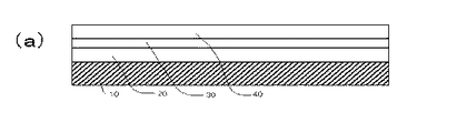
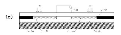
図1の(a)ないし(d)は、上記のように基層を示す模式図である。まず、図1の(a)に示す様に、ガラス基板10の上に第1熱伝導・結晶制御層20が堆積され、その上に非単結晶層30が、さらにその上に第2熱伝導・結晶制御層40が堆積される。次に(c)に示すように、エネルギー線の照射によって、(a)における非単結晶層30が、(c)における単結晶シリコン域50と、非単結晶域51に変成される。(c)に示されているのは、1個の単結晶域の断面の模式図であって、このような単結晶が多数形成されることによって、本発明の薄膜半導体基板となるものである。
【0020】
次に、上記のように形成された薄膜半導体基板上に、(c)に示すように、ゲート電極60を形成し、さらに、このゲート電極60をマスクとし、単結晶半導体薄膜層に燐イオン等の電極形成物質75を注入して、ソース領域70及びドレイン領域71を形成する。
【0021】
次に、(d)に示すように、酸化シリコン等の絶縁物質による層間絶縁膜80を堆積し、さらに、ソース領域70及びドレイン領域71上に位置する第2熱伝導・結晶制御層40及び層間絶縁膜80にコンタクトホールを形成した後アルミニウム(Al)膜を堆積してソース電極90及びドレイン電極91を形成し、それによって、本発明の薄膜半導体装置が完成することになる。
【0022】
上記(b)の工程において、薄膜半導体基板にエネルギー線照射を行うための照射手段としては、例えばエキシマ・レーザ光線の照射を用いるのが好適であるが、必ずしもエキシマ・レーザ光線に限られるものではなく、例えば、連続発振のアルゴン・レーザ光をパルス化して使用することもできる。
【0023】
エネルギー線の照射によって規則的な整列態様で単結晶半導体粒が配置された薄膜半導体層を得るためには、所定の間隔毎に照射エネルギー強度が最大値と最小値との間で二次元的に変化し、エネルギー強度最大点とエネルギー強度最小点とが規則的に整列されたエネルギー強度分布態様で照射が行われるようにする。例えば、図2及び図3に示すように、5×5mmの矩形領域内に、10μmの間隔毎に照射エネルギーが最大値(Emax)→最小値(Emin)→最大値(Emax)の変化を二次元的に(x,y両方向に)繰り返すような強度分布態様で照射を行い、次いで、照射位置を5mm毎に移動させて照射を行うようにすればよい。
【0024】
上記のような照射エネルギー強度の変化は、例えば位相シフト・マスクを用いて照射エネルギー強度分布の変化をもたらすことによって可能であり、また、図3に示すように、最大値と最小値との間の変化が実質的に連続的変化であることが望ましい。
【0025】
最大値、最小値をそれぞれどの程度の値に設定するかは、非単結晶半導体層の膜厚、前記第1、第2の制御層の膜厚や熱伝導率に基づいて調整すればよいが、例えば、最小エネルギー強度は、照射時間内においては薄膜半導体を溶融せしめない照射温度をもたらす強度とし、最大値は薄膜半導体を照射時間内に溶融せしめるに必要かつ十分な強度とし、図3に示すように、最大値(Emax)と最小値(Emin)の間に溶融閾値(Emth)が存在するようにする。
【0026】
なお、照射ユニットの形状は、上記のように5×5mmの正方形状に限られず、各種多角形状でもよいことはもとよりであり、また、照射エネルギーの最大値、最小値の配置形状は、方形格子状に限らず、例えばデルタ形格子状でもよい。
【0027】
上記の態様で薄膜半導体に対してエネルギー線照射を行うと、照射領域のうち照射エネルギーの最小値領域(溶融閾値(Emth)以下の領域)の部分は完全には溶融されずに、まずEmthに相当する温度以下の領域に結晶核が形成され、次いで、結晶核の周囲からEmaxに相当する温度領域に向かって結晶が成長していく(図4の矢印が成長方向を示す)。一方、溶解温度がもっとも高い照射エネルギー最大値領域や結晶成長端付近は、成長方向の異なる結晶がせめぎあって、結果的に微結晶領域部分ないしは粒界となり、かくして、照射エネルギーの溶融閾値(Emth)領域部分を結晶核とする、粒径4μmを超える半導体単結晶が規則的に整列配置された薄膜半導体基板が得られることになる(図4参照)。照射エネルギーの最大値相互間の間隔を調整することによって、単結晶の粒子径を調整しうることはもとよりであり、例えば、XeClエキシマ・レーザ光による波長が308nmのエキシマ・レーザの照射の場合、最大値間の相互間隔を12μmとすることにより、粒径5μmの単結晶が整列配置した薄膜半導体基板を得ることができる。本発明の薄膜半導体装置に用いる基板としては、粒子径は2μm以上であることが望ましい。
【0028】
このようにして、得られた薄膜半導体基板に対し、例えば各単結晶粒毎に位置合わせして、電極形成物質、例えばモリブデン/タングステン合金(MoW)を適宜の厚さ(例えば300nm)で堆積し、所定形状にパターニングしてゲート電極を形成し、このゲート電極をマスクとしてソース領域及びドレイン領域をそれぞれ形成した後、絶縁物質(例えば酸化シリコン)によりゲート電極を囲む層間絶縁膜を形成する。さらに、上記ソース領域及びドレイン領域上の第2の制御層にコンタクト・ホールを形成した後、このホール内に電極物質(例えばアルミニウム)を堆積してパターニングし、ソース電極及びドレイン電極を形成し、これによって、例えば図5の(a)、(b)に示すように、規則的に整列配置された各単結晶毎に1単位の電極回路が整然と配置され、それによって、従来の多結晶半導体薄膜基板を用いた装置の通常の移動度を超える、例えば300cm2/V・sec以上の移動度を有する薄膜半導体装置が得られることになる。
【0029】
必要に応じて、特定の単結晶には電極配置を省略したり、1個の単結晶毎に複数の単位回路を設けるようにすることもできる。また、上記の電極配置手順はNチャンネル型の薄膜トランジスタ製造の場合であるが、部分的にマスクして不純物を順次注入することにより、CMOSトランジスタの構成としうることはもとよりである。さらに、第2制御層を直接にゲート絶縁膜として用いるかわりに、単結晶整列層を形成した後、第2の制御層をエッチング除去してその部分に新たなゲート絶縁膜を形成してもよい。また、隣接トランジスタ間にリーク電流が生じるおそれがある場合には、結晶化前又は結晶化後に、エッチング等により島分離を施してもよい。
【0030】
【実施例】
外形寸法400×500mm、厚さ0.7mm、歪点650℃のコーニング社製の非アルカリガラス基板の表面上に、第1熱伝導・結晶制御層として、200nm厚の酸化シリコン(SiO2)膜をプラズマCVD法により成膜し、その上に、非単結晶半導体層として50nm厚の非晶質シリコン(a−Si:H)膜と、さらにその上に、第2熱伝導・結晶制御層として200nm厚の酸化シリコン膜を、大気に晒すことなく連続して成膜した。
【0031】
次に、上記非晶質シリコン膜層をアニールし、脱水素処理した後、上方から、波長308nmのパルス状エキシマ・レーザ光を照射して非晶質シリコン膜層を結晶化させた。レーザ照射は、エキシマ・レーザ光を5×5mmの短形のレーザ光に整形し、さらに位相シフトマスクにより面内に強度分布を持たせたレーザ光を1照射ユニットとして行った。強度分布は、5×5mmの短形領域内に、10μm間隔で合計25万個所の最大値が正方形格子状に配列する態様のものとした。この実施例では溶融閾値が約0.5J/cm2、レーザ光強度の最大値は1.8J/cm2、最小値は0.1J/cm2であった。
【0032】
上記の態様のエキシマ・レーザ光照射を、照射毎に5mmの間隔でステップ移動させて受光体全面の照射を行った。照射完了後にSeccoエッチング法によるエッチングを施し、走査型電子顕微鏡による観察を行ったところ、粒径4μmの単結晶粒が格子状に規則的に配列している基板が得られたことが分かった。
【0033】
次に、スパッタ法によりモリブデン−タングステン合金(MoW)膜を300nm厚で堆積し、各単結晶粒上に位置合わせして、所定形状にパターニングしてゲート電極を形成した。このゲート電極をマスクとして燐をイオン注入し、ソース及びドレイン領域を形成した。次に、層間シリコン膜としてプラズマCVD法により酸化シリコン膜を堆積し、ソース及びドレイン領域を上の第2熱伝導・結晶制御層及び層間絶縁膜にコンタクトホールを形成し、引き続いてアルミニウム(Al)膜を形成し、薄膜トランジスタ装置を完成させた。この装置の移動度の平均値は496cm2/V・secであった。
【0034】
【発明の効果】
本発明の薄膜半導体装置基板は、基板の薄膜半導体層内に、多数の半導体単結晶粒が規則的整列態様で形成配置されているので、各単結晶粒毎にソース領域、ドレイン領域及びゲート電極を形成配置することにより、単位回路が整然と配置された薄膜半導体装置を得ることができる。
【0035】
本発明の薄膜半導体装置は、各単結晶粒毎にソース電極、ドレイン電極及びゲート電極を有する単位回路が整然と配置されているので、結晶粒界による電子散乱の影響を受けることのない、高移動度の作動効果を得ることができる。
【0036】
本発明の薄膜半導体装置基板製造方法は、非単結晶半導体からなる薄膜半導体層に対し、照射エネルギー強度が最大値となる部分と最小値となる部分とが二次元的に配列される分布態様でエネルギー照射を行うものであるため、それにより、半導体薄膜層内に、多数の大粒径の半導体単結晶粒が規則的整列態様で形成配置された薄膜半導体装置基板を得ることができる。
【0037】
本発明の薄膜半導体装置製造方法は、薄膜半導体層に多数の大粒径の半導体単結晶粒が規則的整列態様で形成配置されている基板を用い、上記半導体単結晶毎に、ソース電極、ドレイン電極及びゲート電極を有する単位回路を形成するようにしたので、それにより、移動度が大きく、かつ電子散乱等の欠陥のない薄膜半導体装置を得ることができる。
【図面の簡単な説明】
【図1】 本発明の薄膜半導体装置の製造過程を示す模式図。
【図2】 エネルギー線照射の際のエネルギー線強度の二次元的分布状態を示す模式図。
【図3】 照射エネルギー線強度の最大値←→最小値間のプロフィルを示す模式図。
【図4】 エネルギー線照射後における単結晶粒の整列状態の一例を示す模式図。
【図5】 本発明の薄膜半導体装置における、結晶粒と電極配置状態の対応関係の一例を示す模式図。
【図6】 従来の多結晶薄膜半導体を用いた薄膜半導体装置における、結晶粒と電極配置状態の対応関係を示す模式図。[0001]
BACKGROUND OF THE INVENTION
The present invention relates to a semiconductor device having a thin film semiconductor layer, a substrate thereof, and a manufacturing method thereof.
[0002]
[Prior art]
As is well known, a thin film semiconductor device or thin film transistor (TFT) uses a substrate in which a thin film layer of a semiconductor material such as silicon is formed on a base layer made of an insulating material such as non-alkali glass or quartz glass. A channel region including a source region and a drain region is formed in the thin film layer, and a gate electrode is provided for each unit channel region via an insulating film.
[0003]
The semiconductor thin film layer is made of amorphous silicon or polycrystalline silicon. However, a TFT using a substrate having an amorphous silicon thin film layer has extremely low mobility (about 1 cm 2 / V · sec). Therefore, it cannot be used for a device that requires a high-speed operation because of its low operation speed. Therefore, recently, in order to increase the mobility, a substrate having a semiconductor thin film layer made of polycrystalline silicon is often used. However, the polycrystalline silicon film is made up of a large number of crystal grains having a very small grain size. For this reason, there is a limit to the improvement in mobility due to the fact that electrons are scattered by crystal grain boundaries during operation of the apparatus.
[0004]
For this reason, it has been studied to obtain a semiconductor substrate having a semiconductor thin film layer that has a high mobility and is hardly affected by electron scattering or the like by increasing the crystal grains of the polycrystalline silicon film. For example, a polycrystalline silicon film is heated in a high-temperature furnace to increase the grain size, thereby forming a thin film layer having crystal grains with a grain size of about 1 μm and exhibiting mobility of about 100 cm 2 / V · sec. There are also attempts. However, in order to increase the particle size, heat treatment at a high temperature of 1000 ° C. or higher is required. Therefore, an expensive quartz glass plate that can withstand high temperatures but must be used as the insulating base layer material is inexpensive. Since a glass plate (for example, soda glass plate) cannot be used, there is a drawback that it is difficult to use for a large screen device.
[0005]
Therefore, without using high-temperature heat treatment, an amorphous silicon film or a polycrystalline silicon film is irradiated with an energy beam such as an excimer laser beam to crystallize or recrystallize silicon to increase the particle size. Several attempts to obtain a polycrystalline silicon thin film layer made of crystal grains have been proposed and put into practical use. According to this method, it is possible to enlarge the crystal grains while using an inexpensive glass plate as the base layer.
[0006]
However, even with a crystallization method using excimer laser light or the like, the obtained crystal grains have a maximum grain size of about 1 μm and are not uniform. For example, in Japanese Patent Application Laid-Open No. 2001-127301, a band-shaped amorphous silicon film is polycrystallized by a melt recrystallization method, an amorphous silicon film is further deposited thereon, and this is formed using a solid phase growth method. Through a series of operations for crystallization, a technique has been proposed in which a crystal film having a large grain size is obtained by growing the crystal using the crystal of the original band-shaped polycrystalline film as a crystal seed. However, this proposal also suggests that the maximum crystal grain size obtained is about 1000 nm (that is, 1 μm), and the grain sizes are not uniform (see FIGS. 2 to 5 in the above-mentioned publication).
[0007]
Further, as a problem that has been overlooked in the conventional polycrystalline semiconductor device, there is a problem of the arrangement of crystal grains in the thin film. That is, in the conventional polycrystalline semiconductor thin film, the arrangement of crystal grains in the two-dimensional direction is completely random, and no attempt has been made to align them. However, the random arrangement of crystal grains, combined with the unevenness of the grain sizes, presents a great difficulty for the thin film transistor device.
[0008]
That is, as a matter of course, the arrangement of the transistor circuits in the thin film semiconductor device is a foundation for circuit formation, although a large number of unit circuits must be arranged regularly and regularly, for example, in a geometric arrangement. If the crystal grain size and crystal arrangement of the polycrystalline layer are not uniform, the unit circuit must be formed across crystal grains having various grain sizes and arrangements (see FIG. 6). This results in a difference in mobility and electron passage mode for each unit circuit, which adversely affects the performance of the thin film semiconductor device. For example, if there are variations in the characteristics of each unit circuit, the entire device must be designed on the basis of low-level characteristics.
[0009]
[Problems to be solved by the invention]
An object of the present invention is to provide a thin film semiconductor device in which unit circuits are arranged according to the arrangement of crystal grains without being arranged across a large number of crystal grains having irregular grain sizes and arrangements. And a method of manufacturing such a device and substrate.
[0010]
[Means for solving problems]
In the thin film semiconductor device of the present invention, a thin film semiconductor substrate in which semiconductor single crystal grains are arranged in a regular alignment state, for example, a substantially geometric alignment state is used. That is, the thin film semiconductor device substrate of the present invention has a base layer made of an insulating material and a thin film semiconductor layer formed on the base layer, and a large number of semiconductor single crystal grains are regularly formed in the thin film semiconductor layer. It is formed and arranged in an alignment mode, and its particle size is large, for example, 2 μm or more.
[0011]
Further, as described above, the thin film semiconductor device of the present invention includes a base layer made of an insulating material and a thin film semiconductor layer formed on the base layer and in which a large number of semiconductor single crystal grains are arranged in a regular alignment manner. A unit circuit having a thin film semiconductor substrate and having a gate electrode for each semiconductor single crystal grain is formed and arranged.
[0012]
In the method for manufacturing a thin film semiconductor device substrate according to the present invention, the non-single crystal semiconductor layer has a portion where the irradiation energy value is maximized and a portion where the irradiation energy value is continuously reduced from the maximum value and is minimized for each irradiation region. Energy beam irradiation is performed in a regularly distributed intensity distribution mode. That is, the method for manufacturing a thin film semiconductor device substrate according to the present invention includes a step of depositing a non-single-crystal semiconductor layer on a base layer made of an insulating material, and irradiating the non-single-crystal semiconductor with an energy beam for crystallization or recrystallization. The energy ray irradiation step is performed in an intensity distribution mode in which a portion where the irradiation energy ray intensity is maximum and a portion where the minimum value is regularly arranged are regularly arranged within a predetermined irradiation area. Is a manufacturing method characterized by
[0013]
Furthermore, in the method for manufacturing a thin film semiconductor device of the present invention, after the thin film semiconductor device substrate is manufactured by the above method, a circuit electrode is formed for each single crystal grain in the thin film semiconductor. That is, the method of manufacturing a thin film semiconductor device of the present invention includes a step of manufacturing a thin film semiconductor device substrate by the above-described method, and a base layer made of an insulating material and a semiconductor single crystal grain formed on the base layer obtained thereby. Forming a gate electrode by alignment for each single crystal grain in a thin film semiconductor substrate having thin film semiconductor layers arranged in a regular alignment mode, and forming a source electrode and a drain electrode for each single crystal grain And a step of forming a unit circuit for each single crystal grain.
[0014]
DETAILED DESCRIPTION OF THE INVENTION
In the thin film semiconductor device of the present invention, it is preferable to use a glass plate having a strain point of 700 ° C. or lower as the insulating material base layer of the thin film semiconductor substrate. However, the invention is not limited to glass, and a plate made of various transparent or opaque insulating materials. For example, ceramic or a plastic film having moderate heat resistance can be used.
[0015]
A semiconductor thin film layer in which semiconductor single crystal grains are arranged in a regular alignment state is formed on the base layer. Such a thin film layer is formed on a base layer of a non-single crystalline semiconductor. This is performed by depositing a thin film layer and forming it into a polycrystalline semiconductor thin film made of a single crystal having a large particle size by an excimer laser or other energy beam irradiation method described later. As the non-single crystalline semiconductor, an amorphous semiconductor may be used, or a polycrystalline semiconductor in which a single crystal having a minute particle diameter has already been formed is recrystallized and the semiconductor thin film layer of the present invention is used. You may form in. The thickness of the thin film semiconductor layer is preferably 10 to 200 nm, particularly 50 to 100 nm.
[0016]
When a non- single- crystal semiconductor layer is formed on a base layer, it is usually made of a material such as a first thermal conduction / crystal control layer such as silicon oxide or silicon nitride (SiNx) between the base layer and the semiconductor layer. A thin layer is formed. This layer has a function of blocking impurities from the base layer material (for example, glass) and a function of bringing about uniformity of the heat distribution of the semiconductor layer and crystal orientation in the irradiation crystallization process. 20 to 1000 nm, particularly 200 to 300 nm.
[0017]
In addition, a second heat conduction / crystal control layer is usually provided on the non- single crystal semiconductor layer. Similar to the first heat conduction / crystal control layer, this layer also has the function of providing the heat distribution uniformity and crystal orientation of the semiconductor layer in the irradiation crystallization process. Silicon oxide, silicon nitride, silicon carbide A substance such as (SiC) can be used. The film thickness is desirably 50 to 500 nm, particularly 100 to 300 nm.
[0018]
When the first and second thermal conduction / crystal control layers are formed, the thin single crystal semiconductor layer is formed between the two control layers. In this case, Depositing a first control layer material on the insulating material base layer in a thin film; depositing a thin film amorphous semiconductor material layer thereon; and depositing a second control layer material layer thereon; The non-single crystal semiconductor layer is single crystallized by irradiating energy rays from above.
[0019]
(A) thru | or (d) of FIG. 1 is a schematic diagram which shows a base layer as mentioned above. First, as shown in FIG. 1A, a first heat conduction /
[0020]
Next, on the thin film semiconductor substrate formed as described above, a gate electrode 60 is formed as shown in (c). Further, using this gate electrode 60 as a mask, phosphorous ions or the like are formed on the single crystal semiconductor thin film layer. The
[0021]
Next, as shown in FIG. 4D, an interlayer insulating film 80 made of an insulating material such as silicon oxide is deposited, and the second heat conduction / crystal control layer 40 and the interlayer located on the
[0022]
In the step (b), it is preferable to use, for example, excimer laser beam irradiation as the irradiation means for irradiating the thin film semiconductor substrate with energy rays, but it is not necessarily limited to the excimer laser beam. Alternatively, for example, a continuous wave argon laser beam can be pulsed and used.
[0023]
In order to obtain a thin film semiconductor layer in which single crystal semiconductor grains are arranged in a regular alignment mode by irradiation with energy rays, the irradiation energy intensity is two-dimensionally between a maximum value and a minimum value at predetermined intervals. The irradiation is performed in an energy intensity distribution manner in which the energy intensity maximum point and the energy intensity minimum point are regularly aligned. For example, as shown in FIG. 2 and FIG. 3, in a rectangular region of 5 × 5 mm, the irradiation energy changes in a maximum value (Emax) → minimum value (Emin) → maximum value (Emax) at intervals of 10 μm. Irradiation may be performed in such an intensity distribution manner that it repeats dimensionally (in both x and y directions), and then the irradiation position is moved every 5 mm.
[0024]
The change in the irradiation energy intensity as described above is possible by causing a change in the irradiation energy intensity distribution using, for example, a phase shift mask, and between the maximum value and the minimum value as shown in FIG. It is desirable that the change in is a substantially continuous change.
[0025]
How much the maximum value and the minimum value are set may be adjusted based on the film thickness of the non-single crystal semiconductor layer, the film thickness of the first and second control layers, and the thermal conductivity. For example, the minimum energy intensity is an intensity that provides an irradiation temperature at which the thin film semiconductor is not melted within the irradiation time, and the maximum value is an intensity that is necessary and sufficient to melt the thin film semiconductor within the irradiation time, as shown in FIG. As described above, the melting threshold (Emth) exists between the maximum value (Emax) and the minimum value (Emin).
[0026]
The shape of the irradiation unit is not limited to the 5 × 5 mm square shape as described above, but may be various polygonal shapes, and the arrangement shape of the maximum value and the minimum value of the irradiation energy is a rectangular lattice. For example, a delta lattice shape may be used.
[0027]
When energy beam irradiation is performed on the thin film semiconductor in the above-described manner, the portion of the irradiation region where the irradiation energy is minimum (the region below the melting threshold (Eth)) is not completely melted. Crystal nuclei are formed in regions below the corresponding temperature, and then crystals grow from the periphery of the crystal nuclei toward the temperature region corresponding to Emax (the arrow in FIG. 4 indicates the growth direction). On the other hand, in the irradiation energy maximum value region where the melting temperature is the highest and in the vicinity of the crystal growth end, crystals with different growth directions are intermingled, resulting in a microcrystalline region part or a grain boundary. ) A thin film semiconductor substrate in which semiconductor single crystals having a grain size of 4 μm and having a region portion as a crystal nucleus are regularly arranged and arranged is obtained (see FIG. 4). The particle diameter of the single crystal can be adjusted by adjusting the interval between the maximum values of the irradiation energy. For example, in the case of irradiation with an excimer laser having a wavelength of 308 nm by XeCl excimer laser light, By setting the mutual interval between the maximum values to 12 μm, it is possible to obtain a thin film semiconductor substrate in which single crystals having a particle diameter of 5 μm are arranged and arranged. The substrate used in the thin film semiconductor device of the present invention preferably has a particle size of 2 μm or more.
[0028]
In this way, an electrode forming material, for example, a molybdenum / tungsten alloy (MoW) is deposited at an appropriate thickness (for example, 300 nm) on the thin film semiconductor substrate thus obtained, for example, aligned for each single crystal grain. Then, a gate electrode is formed by patterning into a predetermined shape, and after forming a source region and a drain region using this gate electrode as a mask, an interlayer insulating film surrounding the gate electrode is formed by an insulating material (for example, silicon oxide). Further, after forming a contact hole in the second control layer on the source region and the drain region, an electrode material (for example, aluminum) is deposited and patterned in the hole to form a source electrode and a drain electrode, As a result, for example, as shown in FIGS. 5A and 5B, one unit of electrode circuit is regularly arranged for each regularly arranged single crystal, whereby a conventional polycrystalline semiconductor thin film is formed. A thin film semiconductor device having a mobility exceeding the normal mobility of the device using the substrate, for example, 300 cm 2 / V · sec or more can be obtained.
[0029]
If necessary, electrode arrangement may be omitted for a specific single crystal, or a plurality of unit circuits may be provided for each single crystal. The above electrode arrangement procedure is for the manufacture of an N-channel type thin film transistor. However, it is possible to form a CMOS transistor by partially implanting impurities while partially masking. Further, instead of directly using the second control layer as the gate insulating film, after forming the single crystal alignment layer, the second control layer may be removed by etching to form a new gate insulating film there. . If there is a risk of leakage current between adjacent transistors, island isolation may be performed by etching or the like before or after crystallization.
[0030]
【Example】
A 200 nm-thick silicon oxide (SiO 2 ) film as a first heat conduction / crystal control layer on the surface of a non-alkali glass substrate manufactured by Corning with external dimensions of 400 × 500 mm, a thickness of 0.7 mm, and a strain point of 650 ° C. As a non-single crystal semiconductor layer, an amorphous silicon (a-Si: H) film having a thickness of 50 nm is formed thereon, and a second thermal conduction / crystal control layer is further formed thereon. A 200 nm thick silicon oxide film was continuously formed without being exposed to the atmosphere.
[0031]
Next, after annealing and dehydrogenating the amorphous silicon film layer, the amorphous silicon film layer was crystallized by irradiating a pulsed excimer laser beam having a wavelength of 308 nm from above. The laser irradiation was performed using one laser beam, which was obtained by shaping the excimer laser beam into a 5 × 5 mm short laser beam, and having an in-plane intensity distribution with a phase shift mask. The intensity distribution was such that a maximum value of a total of 250,000 locations was arranged in a square lattice pattern at intervals of 10 μm within a 5 × 5 mm short region. In this example, the melting threshold was about 0.5 J / cm 2 , the maximum value of laser light intensity was 1.8 J / cm 2 , and the minimum value was 0.1 J / cm 2 .
[0032]
The excimer laser light irradiation of the above aspect was stepped at intervals of 5 mm for each irradiation to irradiate the entire surface of the photoreceptor. After completion of irradiation, etching by the Secco etching method was performed, and observation with a scanning electron microscope revealed that a substrate in which single crystal grains having a grain size of 4 μm were regularly arranged in a lattice shape was obtained.
[0033]
Next, a molybdenum-tungsten alloy (MoW) film having a thickness of 300 nm was deposited by sputtering, aligned on each single crystal grain, and patterned into a predetermined shape to form a gate electrode. Using this gate electrode as a mask, phosphorus ions were implanted to form source and drain regions. Next, a silicon oxide film is deposited by plasma CVD as an interlayer silicon film, and contact holes are formed in the source and drain regions in the second heat conduction / crystal control layer and the interlayer insulating film, followed by aluminum (Al). A film was formed to complete the thin film transistor device. The average mobility of this device was 496 cm 2 / V · sec.
[0034]
【The invention's effect】
In the thin film semiconductor device substrate of the present invention, since a large number of semiconductor single crystal grains are formed and arranged in a regularly aligned manner in the thin film semiconductor layer of the substrate, a source region, a drain region and a gate electrode are provided for each single crystal grain. Thus, a thin film semiconductor device in which unit circuits are arranged in an orderly manner can be obtained.
[0035]
In the thin film semiconductor device of the present invention, unit circuits each having a source electrode, a drain electrode, and a gate electrode are regularly arranged for each single crystal grain, so that the high mobility without being affected by electron scattering by the crystal grain boundary. A degree of operation effect can be obtained.
[0036]
The thin film semiconductor device substrate manufacturing method of the present invention has a distribution mode in which a portion having a maximum irradiation energy intensity and a portion having a minimum value are two-dimensionally arranged on a thin film semiconductor layer made of a non-single crystal semiconductor. Since energy irradiation is performed, it is possible to obtain a thin film semiconductor device substrate in which a large number of large semiconductor single crystal grains are formed and arranged in a regular alignment manner in the semiconductor thin film layer.
[0037]
The thin film semiconductor device manufacturing method of the present invention uses a substrate in which a large number of large semiconductor single crystal grains are formed and arranged in a thin film semiconductor layer in a regular alignment mode, and each of the semiconductor single crystals has a source electrode and a drain. Since a unit circuit having an electrode and a gate electrode is formed, a thin film semiconductor device having high mobility and no defects such as electron scattering can be obtained.
[Brief description of the drawings]
FIG. 1 is a schematic view showing a manufacturing process of a thin film semiconductor device of the present invention.
FIG. 2 is a schematic diagram showing a two-dimensional distribution state of energy beam intensity at the time of energy beam irradiation.
FIG. 3 is a schematic diagram showing a profile between the maximum value ← → minimum value of the irradiation energy ray intensity.
FIG. 4 is a schematic diagram showing an example of the alignment state of single crystal grains after energy beam irradiation.
FIG. 5 is a schematic diagram showing an example of the correspondence between crystal grains and electrode arrangement states in the thin film semiconductor device of the present invention.
FIG. 6 is a schematic diagram showing a correspondence relationship between crystal grains and electrode arrangement states in a conventional thin film semiconductor device using a polycrystalline thin film semiconductor.
Claims (1)
上記第1熱伝導・結晶制御層は200nmないし300nmの膜厚を有し、上記第2熱伝導・結晶制御層は100nmないし300nmの膜厚を有するものであり、
上記エネルギー線の照射による結晶化工程は、所定の照射面積内において、照射エネルギー線強度が最大値となる領域と最大値から連続的に低減して最小値となる領域とが二次元方向において規則的に繰り返して配列される強度分布態様を有するエネルギー線照射によって行い、
上記最大値の照射エネルギー線強度は上記非単結晶半導体層を上記照射時間内で溶融せしめるに必要かつ十分な強度とし、上記最小値の照射エネルギー線強度は上記非単結晶半導体層を上記照射時間内で溶融せしめない強度とし、
上記照射強度分布態様の照射エネルギー線の照射により、上記最大値の照射エネルギー線強度領域と上記最小値の照射エネルギー線強度領域の間の、完全には溶融されない非単結晶半導体層の領域に結晶核を形成させ、上記結晶核の周囲から上記最大値の照射エネルギー強度領域に向かって結晶を成長させて、溶解温度がもっとも高い上記最大値の照射エネルギー線強度領域や結晶成長端付近は、成長方向の異なる結晶がせめぎあって、結果的に微結晶領域部分ないし粒界となり、かくして、粒径2μm以上の単結晶粒が層内に二次元方向に規則的に整列配置された半導体層を形成する工程とし、
上記の結晶化工程によって得られた、絶縁材からなる基層と、基層上に形成されて粒径2μm以上の半導体単結晶粒が二次元方向において規則的整列態様で配置されている薄膜半導体層と、を有する薄膜半導体装置基板内の、上記単結晶粒上にゲート絶縁膜を介してゲート電極を形成する工程と、
上記ゲート電極が形成された上記半導体単結晶粒に複数のソース電極及びドレイン電極を形成し、各単結晶粒毎に複数の単位回路を形成する工程と、
を有することを特徴とする薄膜半導体装置の製造方法。A first heat conduction / crystal control layer, a non-single crystal semiconductor layer, and a second heat conduction / crystal control layer are sequentially formed on a base layer made of an insulating material , and the non-monocrystalline semiconductor layer is interposed through the second heat conduction / crystal control layer. By irradiating the single crystal semiconductor layer with energy rays to crystallize or recrystallize the non-single crystal semiconductor layer, and then performing irradiation by sequentially moving the irradiation position, the non-single crystal semiconductor layer is predetermined. A method of manufacturing a thin film semiconductor device comprising: crystallizing a position;
The first thermal conduction / crystal control layer has a thickness of 200 nm to 300 nm, and the second thermal conduction / crystal control layer has a thickness of 100 nm to 300 nm ,
In the crystallization process by irradiation with energy rays, a region where the intensity of irradiation energy rays becomes a maximum value and a region where the irradiation energy ray intensity continuously decreases from the maximum value and becomes a minimum value within a predetermined irradiation area are regular in a two-dimensional direction. Is performed by irradiation with energy rays having an intensity distribution mode that is repeatedly arranged,
The maximum irradiation energy ray intensity is necessary and sufficient to melt the non-single crystal semiconductor layer within the irradiation time, and the minimum irradiation energy ray intensity is the irradiation time of the non-single crystal semiconductor layer. With a strength that does not melt within
By irradiation with the irradiation energy line in the irradiation intensity distribution mode, a crystal is formed in a region of the non-single crystal semiconductor layer that is not completely melted between the maximum irradiation energy ray intensity region and the minimum irradiation energy ray intensity region. A nucleus is formed, and a crystal is grown from the periphery of the crystal nucleus toward the irradiation energy intensity region having the maximum value. Crystals with different directions are intermingled, resulting in microcrystalline region portions or grain boundaries, thus forming a semiconductor layer in which single crystal grains having a grain size of 2 μm or more are regularly arranged in a two-dimensional direction within the layer. And the process to
A base layer made of an insulating material obtained by the crystallization step, and a thin film semiconductor layer in which semiconductor single crystal grains formed on the base layer and having a grain size of 2 μm or more are regularly arranged in a two-dimensional direction; Forming a gate electrode on the single crystal grain through a gate insulating film in a thin film semiconductor device substrate having
Forming a plurality of source electrodes and drain electrodes on the semiconductor single crystal grain on which the gate electrode is formed, and forming a plurality of unit circuits for each single crystal grain;
A method for manufacturing a thin film semiconductor device, comprising:
Priority Applications (9)
| Application Number | Priority Date | Filing Date | Title |
|---|---|---|---|
| JP2001218370A JP4784955B2 (en) | 2001-07-18 | 2001-07-18 | Method for manufacturing thin film semiconductor device |
| TW091114798A TW558838B (en) | 2001-07-18 | 2002-07-04 | A thin film semiconductor device having arrayed configuration of semiconductor crystals and a method for producing it |
| CNB028022637A CN1276471C (en) | 2001-07-18 | 2002-07-10 | Method of producing semiconductor thin film, method of producing semiconductor device, semiconductor device, integrated circuit, electrooptical device and electronic apparatus |
| CNB2006100594857A CN100468765C (en) | 2001-07-18 | 2002-07-10 | Thin film semiconductor device |
| PCT/JP2002/006981 WO2003009351A1 (en) | 2001-07-18 | 2002-07-10 | Thin-film semiconductor device and its production method |
| EP20020745896 EP1416522A4 (en) | 2001-07-18 | 2002-07-10 | Thin-film semiconductor device and its production method |
| KR1020037003842A KR100792323B1 (en) | 2001-07-18 | 2002-07-10 | Thin-film semiconductor device and its production method |
| US10/192,850 US6828178B2 (en) | 2001-07-18 | 2002-07-11 | Thin film semiconductor device having arrayed configuration of semiconductor crystals and a method for producing it |
| US10/975,845 US20050085002A1 (en) | 2001-07-17 | 2004-10-29 | Thin film semiconductor device and its substrate sheet as well as the method for production thereof |
Applications Claiming Priority (1)
| Application Number | Priority Date | Filing Date | Title |
|---|---|---|---|
| JP2001218370A JP4784955B2 (en) | 2001-07-18 | 2001-07-18 | Method for manufacturing thin film semiconductor device |
Publications (3)
| Publication Number | Publication Date |
|---|---|
| JP2003031497A JP2003031497A (en) | 2003-01-31 |
| JP2003031497A5 JP2003031497A5 (en) | 2005-09-08 |
| JP4784955B2 true JP4784955B2 (en) | 2011-10-05 |
Family
ID=19052554
Family Applications (1)
| Application Number | Title | Priority Date | Filing Date |
|---|---|---|---|
| JP2001218370A Expired - Fee Related JP4784955B2 (en) | 2001-07-17 | 2001-07-18 | Method for manufacturing thin film semiconductor device |
Country Status (7)
| Country | Link |
|---|---|
| US (2) | US6828178B2 (en) |
| EP (1) | EP1416522A4 (en) |
| JP (1) | JP4784955B2 (en) |
| KR (1) | KR100792323B1 (en) |
| CN (2) | CN100468765C (en) |
| TW (1) | TW558838B (en) |
| WO (1) | WO2003009351A1 (en) |
Families Citing this family (14)
| Publication number | Priority date | Publication date | Assignee | Title |
|---|---|---|---|---|
| JP4310076B2 (en) * | 2001-05-31 | 2009-08-05 | キヤノン株式会社 | Method for producing crystalline thin film |
| JP4813743B2 (en) * | 2002-07-24 | 2011-11-09 | 株式会社 日立ディスプレイズ | Manufacturing method of image display device |
| JP4524413B2 (en) * | 2003-06-30 | 2010-08-18 | シャープ株式会社 | Crystallization method |
| TW200503061A (en) * | 2003-06-30 | 2005-01-16 | Adv Lcd Tech Dev Ct Co Ltd | Crystallization method, crystallization apparatus, processed substrate, thin film transistor and display apparatus |
| JP2010114472A (en) * | 2003-06-30 | 2010-05-20 | Advanced Lcd Technologies Development Center Co Ltd | Method of crystallization |
| JP2005109352A (en) * | 2003-10-01 | 2005-04-21 | Advanced Lcd Technologies Development Center Co Ltd | Thin-film semiconductor structure for annealing, annealing method for the thin-film semiconductor, thin-film semiconductor device, manufacturing method of the thin-film semiconductor device, and display |
| JP2005191173A (en) * | 2003-12-25 | 2005-07-14 | Hitachi Ltd | Display and its manufacturing method |
| TW200541079A (en) | 2004-06-04 | 2005-12-16 | Adv Lcd Tech Dev Ct Co Ltd | Crystallizing method, thin-film transistor manufacturing method, thin-film transistor, and display device |
| JP4834853B2 (en) | 2004-06-10 | 2011-12-14 | シャープ株式会社 | THIN FILM TRANSISTOR CIRCUIT, THIN FILM TRANSISTOR CIRCUIT DESIGN METHOD, THIN FILM TRANSISTOR CIRCUIT DESIGN PROGRAM, DESIGN PROGRAM RECORDING MEDIUM, AND DISPLAY DEVICE |
| CN1707774A (en) * | 2004-06-10 | 2005-12-14 | 株式会社液晶先端技术开发中心 | Thin-film transistor circuit, design method for thin-film transistor, design program for thin-film transistor circuit, design program recording medium |
| KR100646937B1 (en) * | 2005-08-22 | 2006-11-23 | 삼성에스디아이 주식회사 | Poly silicon thin film transistor and method for fabricating the same |
| JP2010034366A (en) | 2008-07-30 | 2010-02-12 | Sony Corp | Semiconductor processing apparatus, and semiconductor processing method |
| KR100998257B1 (en) | 2008-08-06 | 2010-12-03 | 한양대학교 산학협력단 | Method for crystallizing an amorphous thin film and wiring structure for performing the same |
| JP2010263240A (en) * | 2010-07-27 | 2010-11-18 | Sharp Corp | Crystallization method, crystallization device, thin film transistor, and display device |
Family Cites Families (24)
| Publication number | Priority date | Publication date | Assignee | Title |
|---|---|---|---|---|
| JP3287834B2 (en) * | 1989-11-16 | 2002-06-04 | ソニー株式会社 | Heat treatment method for polycrystalline semiconductor thin film |
| JP2900588B2 (en) * | 1990-11-16 | 1999-06-02 | キヤノン株式会社 | Crystal article forming method |
| JP3343098B2 (en) * | 1990-11-28 | 2002-11-11 | シャープ株式会社 | Active matrix display device |
| JPH06289431A (en) * | 1993-03-31 | 1994-10-18 | A G Technol Kk | Formation of thin-film transistor and active matrix display element |
| JP3326654B2 (en) * | 1994-05-02 | 2002-09-24 | ソニー株式会社 | Method of manufacturing semiconductor chip for display |
| JP3897826B2 (en) * | 1994-08-19 | 2007-03-28 | 株式会社半導体エネルギー研究所 | Active matrix display device |
| JP2647020B2 (en) * | 1994-09-27 | 1997-08-27 | セイコーエプソン株式会社 | Complementary thin film transistor and method of manufacturing the same |
| JP3675886B2 (en) * | 1995-03-17 | 2005-07-27 | 株式会社半導体エネルギー研究所 | Method for manufacturing thin film semiconductor device |
| JP3850461B2 (en) * | 1995-04-26 | 2006-11-29 | 株式会社半導体エネルギー研究所 | Method for manufacturing semiconductor device |
| JPH0917729A (en) * | 1995-06-29 | 1997-01-17 | Sharp Corp | Manufacture of semiconductor device |
| JPH0955509A (en) * | 1995-08-11 | 1997-02-25 | Sharp Corp | Manufacture of semiconductor device |
| US5977559A (en) * | 1995-09-29 | 1999-11-02 | Semiconductor Energy Laboratory Co., Ltd. | Thin-film transistor having a catalyst element in its active regions |
| US6190949B1 (en) * | 1996-05-22 | 2001-02-20 | Sony Corporation | Silicon thin film, group of silicon single crystal grains and formation process thereof, and semiconductor device, flash memory cell and fabrication process thereof |
| JPH10261799A (en) * | 1997-03-18 | 1998-09-29 | Sony Corp | Manufacture of semiconductor substrate and manufacture of semiconductor device |
| JPH11145056A (en) * | 1997-11-07 | 1999-05-28 | Sony Corp | Semiconductor material |
| JP2000223419A (en) * | 1998-06-30 | 2000-08-11 | Sony Corp | Method of forming single crystal silicon layer, and semiconductor device and manufacture thereof |
| JP3156776B2 (en) * | 1998-08-03 | 2001-04-16 | 日本電気株式会社 | Laser irradiation method |
| JP2000082669A (en) * | 1998-09-07 | 2000-03-21 | Japan Science & Technology Corp | Manufacture of polycrystalline semiconductor film for solar battery |
| JP3237630B2 (en) * | 1998-11-13 | 2001-12-10 | 日本電気株式会社 | Method for manufacturing thin film transistor |
| JP2000252212A (en) * | 1998-12-29 | 2000-09-14 | Semiconductor Energy Lab Co Ltd | Manufacture of semiconductor device |
| JP4403599B2 (en) * | 1999-04-19 | 2010-01-27 | ソニー株式会社 | Semiconductor thin film crystallization method, laser irradiation apparatus, thin film transistor manufacturing method, and display apparatus manufacturing method |
| JP3540262B2 (en) * | 1999-09-16 | 2004-07-07 | 松下電器産業株式会社 | Method of manufacturing thin film transistor and method of manufacturing display device using the same |
| JP4906017B2 (en) * | 1999-09-24 | 2012-03-28 | 株式会社半導体エネルギー研究所 | Display device |
| JP2001144296A (en) * | 1999-11-12 | 2001-05-25 | Toshiba Corp | Polycrystal semiconductor device |
-
2001
- 2001-07-18 JP JP2001218370A patent/JP4784955B2/en not_active Expired - Fee Related
-
2002
- 2002-07-04 TW TW091114798A patent/TW558838B/en not_active IP Right Cessation
- 2002-07-10 CN CNB2006100594857A patent/CN100468765C/en not_active Expired - Fee Related
- 2002-07-10 KR KR1020037003842A patent/KR100792323B1/en not_active IP Right Cessation
- 2002-07-10 WO PCT/JP2002/006981 patent/WO2003009351A1/en active Application Filing
- 2002-07-10 CN CNB028022637A patent/CN1276471C/en not_active Expired - Fee Related
- 2002-07-10 EP EP20020745896 patent/EP1416522A4/en not_active Withdrawn
- 2002-07-11 US US10/192,850 patent/US6828178B2/en not_active Expired - Fee Related
-
2004
- 2004-10-29 US US10/975,845 patent/US20050085002A1/en not_active Abandoned
Also Published As
| Publication number | Publication date |
|---|---|
| EP1416522A1 (en) | 2004-05-06 |
| CN1276471C (en) | 2006-09-20 |
| US6828178B2 (en) | 2004-12-07 |
| CN1465092A (en) | 2003-12-31 |
| CN1841765A (en) | 2006-10-04 |
| EP1416522A4 (en) | 2005-09-21 |
| KR20040028613A (en) | 2004-04-03 |
| CN100468765C (en) | 2009-03-11 |
| KR100792323B1 (en) | 2008-01-07 |
| US20050085002A1 (en) | 2005-04-21 |
| EP1416522A8 (en) | 2004-08-04 |
| US20030027410A1 (en) | 2003-02-06 |
| WO2003009351A1 (en) | 2003-01-30 |
| JP2003031497A (en) | 2003-01-31 |
| TW558838B (en) | 2003-10-21 |
Similar Documents
| Publication | Publication Date | Title |
|---|---|---|
| TW527731B (en) | Method for crystallizing silicon layer | |
| KR100671212B1 (en) | Method for forming poly silicon | |
| US7067404B2 (en) | Thin film semiconductor device having a gate electrode insulator formed through high-heat oxidization | |
| JP4784955B2 (en) | Method for manufacturing thin film semiconductor device | |
| JP2004087535A (en) | Method for manufacturing crystalline semiconductor material and method for manufacturing semiconductor device | |
| KR100390523B1 (en) | Method for crystallizing silicone layer | |
| KR20030069779A (en) | Thin film transistor and method for manufacturing thereof | |
| KR100333275B1 (en) | TFT of LCD device and the same methode | |
| JP2006060185A (en) | Manufacturing method of thin film transistor | |
| JP4084039B2 (en) | Thin film semiconductor device and manufacturing method thereof | |
| JP4203141B2 (en) | Method for crystallizing amorphous silicon layer and method for producing thin film transistor using the same | |
| JP2003031497A5 (en) | ||
| KR100660814B1 (en) | method for fabricating semiconductor layer for thin film transistor | |
| KR100710621B1 (en) | Method for fabricating active layer for TFT type array substrate | |
| JPH07176757A (en) | Manufacture of thin film transistor | |
| TWI233457B (en) | Method of forming poly-silicon crystallization | |
| KR101009429B1 (en) | Polycrystalline silicon layer, thin film transistor comprising the same, and fabricating method of the same | |
| JPH02275641A (en) | Manufacture of semiconductor device | |
| JP2005005381A (en) | Method of manufacturing crystalline semiconductor material and semiconductor device | |
| KR20030015617A (en) | Method of manufacturing a crystalloid silicone | |
| JPH03159116A (en) | Method for thermally treating thin polycrystal semiconductor film | |
| KR100860007B1 (en) | Thin Film Transistor, The Fabricating Method Of Thin Film Transistor, Organic Light Emitting Display Device and The Fabricating Method of Organic Light Emitting Display Device | |
| JP2876598B2 (en) | Method for manufacturing semiconductor device | |
| KR100599966B1 (en) | Method for fabricating polysilicon thin film transistor | |
| JP4271453B2 (en) | Semiconductor crystallization method and thin film transistor manufacturing method |
Legal Events
| Date | Code | Title | Description |
|---|---|---|---|
| A521 | Request for written amendment filed |
Free format text: JAPANESE INTERMEDIATE CODE: A523 Effective date: 20050316 |
|
| A621 | Written request for application examination |
Free format text: JAPANESE INTERMEDIATE CODE: A621 Effective date: 20050316 |
|
| A131 | Notification of reasons for refusal |
Free format text: JAPANESE INTERMEDIATE CODE: A131 Effective date: 20081021 |
|
| A521 | Request for written amendment filed |
Free format text: JAPANESE INTERMEDIATE CODE: A523 Effective date: 20081222 |
|
| A02 | Decision of refusal |
Free format text: JAPANESE INTERMEDIATE CODE: A02 Effective date: 20090203 |
|
| A521 | Request for written amendment filed |
Free format text: JAPANESE INTERMEDIATE CODE: A523 Effective date: 20090403 |
|
| A521 | Request for written amendment filed |
Free format text: JAPANESE INTERMEDIATE CODE: A523 Effective date: 20090423 |
|
| A911 | Transfer to examiner for re-examination before appeal (zenchi) |
Free format text: JAPANESE INTERMEDIATE CODE: A911 Effective date: 20090428 |
|
| A912 | Re-examination (zenchi) completed and case transferred to appeal board |
Free format text: JAPANESE INTERMEDIATE CODE: A912 Effective date: 20090710 |
|
| A521 | Request for written amendment filed |
Free format text: JAPANESE INTERMEDIATE CODE: A523 Effective date: 20110527 |
|
| A01 | Written decision to grant a patent or to grant a registration (utility model) |
Free format text: JAPANESE INTERMEDIATE CODE: A01 |
|
| A61 | First payment of annual fees (during grant procedure) |
Free format text: JAPANESE INTERMEDIATE CODE: A61 Effective date: 20110706 |
|
| R150 | Certificate of patent or registration of utility model |
Free format text: JAPANESE INTERMEDIATE CODE: R150 |
|
| FPAY | Renewal fee payment (event date is renewal date of database) |
Free format text: PAYMENT UNTIL: 20140722 Year of fee payment: 3 |
|
| S111 | Request for change of ownership or part of ownership |
Free format text: JAPANESE INTERMEDIATE CODE: R313113 |
|
| FPAY | Renewal fee payment (event date is renewal date of database) |
Free format text: PAYMENT UNTIL: 20140722 Year of fee payment: 3 |
|
| R350 | Written notification of registration of transfer |
Free format text: JAPANESE INTERMEDIATE CODE: R350 |
|
| R250 | Receipt of annual fees |
Free format text: JAPANESE INTERMEDIATE CODE: R250 |
|
| R250 | Receipt of annual fees |
Free format text: JAPANESE INTERMEDIATE CODE: R250 |
|
| LAPS | Cancellation because of no payment of annual fees |