JP4765700B2 - Power converter - Google Patents
Power converter Download PDFInfo
- Publication number
- JP4765700B2 JP4765700B2 JP2006074652A JP2006074652A JP4765700B2 JP 4765700 B2 JP4765700 B2 JP 4765700B2 JP 2006074652 A JP2006074652 A JP 2006074652A JP 2006074652 A JP2006074652 A JP 2006074652A JP 4765700 B2 JP4765700 B2 JP 4765700B2
- Authority
- JP
- Japan
- Prior art keywords
- command value
- motor
- power
- voltage
- value
- Prior art date
- Legal status (The legal status is an assumption and is not a legal conclusion. Google has not performed a legal analysis and makes no representation as to the accuracy of the status listed.)
- Active
Links
Images


Classifications
-
- H—ELECTRICITY
- H02—GENERATION; CONVERSION OR DISTRIBUTION OF ELECTRIC POWER
- H02M—APPARATUS FOR CONVERSION BETWEEN AC AND AC, BETWEEN AC AND DC, OR BETWEEN DC AND DC, AND FOR USE WITH MAINS OR SIMILAR POWER SUPPLY SYSTEMS; CONVERSION OF DC OR AC INPUT POWER INTO SURGE OUTPUT POWER; CONTROL OR REGULATION THEREOF
- H02M7/00—Conversion of ac power input into dc power output; Conversion of dc power input into ac power output
- H02M7/42—Conversion of dc power input into ac power output without possibility of reversal
- H02M7/44—Conversion of dc power input into ac power output without possibility of reversal by static converters
- H02M7/48—Conversion of dc power input into ac power output without possibility of reversal by static converters using discharge tubes with control electrode or semiconductor devices with control electrode
- H02M7/53—Conversion of dc power input into ac power output without possibility of reversal by static converters using discharge tubes with control electrode or semiconductor devices with control electrode using devices of a triode or transistor type requiring continuous application of a control signal
- H02M7/537—Conversion of dc power input into ac power output without possibility of reversal by static converters using discharge tubes with control electrode or semiconductor devices with control electrode using devices of a triode or transistor type requiring continuous application of a control signal using semiconductor devices only, e.g. single switched pulse inverters
- H02M7/5387—Conversion of dc power input into ac power output without possibility of reversal by static converters using discharge tubes with control electrode or semiconductor devices with control electrode using devices of a triode or transistor type requiring continuous application of a control signal using semiconductor devices only, e.g. single switched pulse inverters in a bridge configuration
- H02M7/5388—Conversion of dc power input into ac power output without possibility of reversal by static converters using discharge tubes with control electrode or semiconductor devices with control electrode using devices of a triode or transistor type requiring continuous application of a control signal using semiconductor devices only, e.g. single switched pulse inverters in a bridge configuration with asymmetrical configuration of switches
-
- B—PERFORMING OPERATIONS; TRANSPORTING
- B60—VEHICLES IN GENERAL
- B60L—PROPULSION OF ELECTRICALLY-PROPELLED VEHICLES; SUPPLYING ELECTRIC POWER FOR AUXILIARY EQUIPMENT OF ELECTRICALLY-PROPELLED VEHICLES; ELECTRODYNAMIC BRAKE SYSTEMS FOR VEHICLES IN GENERAL; MAGNETIC SUSPENSION OR LEVITATION FOR VEHICLES; MONITORING OPERATING VARIABLES OF ELECTRICALLY-PROPELLED VEHICLES; ELECTRIC SAFETY DEVICES FOR ELECTRICALLY-PROPELLED VEHICLES
- B60L15/00—Methods, circuits, or devices for controlling the traction-motor speed of electrically-propelled vehicles
- B60L15/02—Methods, circuits, or devices for controlling the traction-motor speed of electrically-propelled vehicles characterised by the form of the current used in the control circuit
- B60L15/025—Methods, circuits, or devices for controlling the traction-motor speed of electrically-propelled vehicles characterised by the form of the current used in the control circuit using field orientation; Vector control; Direct Torque Control [DTC]
-
- H—ELECTRICITY
- H02—GENERATION; CONVERSION OR DISTRIBUTION OF ELECTRIC POWER
- H02M—APPARATUS FOR CONVERSION BETWEEN AC AND AC, BETWEEN AC AND DC, OR BETWEEN DC AND DC, AND FOR USE WITH MAINS OR SIMILAR POWER SUPPLY SYSTEMS; CONVERSION OF DC OR AC INPUT POWER INTO SURGE OUTPUT POWER; CONTROL OR REGULATION THEREOF
- H02M7/00—Conversion of ac power input into dc power output; Conversion of dc power input into ac power output
- H02M7/42—Conversion of dc power input into ac power output without possibility of reversal
- H02M7/44—Conversion of dc power input into ac power output without possibility of reversal by static converters
- H02M7/48—Conversion of dc power input into ac power output without possibility of reversal by static converters using discharge tubes with control electrode or semiconductor devices with control electrode
- H02M7/53—Conversion of dc power input into ac power output without possibility of reversal by static converters using discharge tubes with control electrode or semiconductor devices with control electrode using devices of a triode or transistor type requiring continuous application of a control signal
- H02M7/537—Conversion of dc power input into ac power output without possibility of reversal by static converters using discharge tubes with control electrode or semiconductor devices with control electrode using devices of a triode or transistor type requiring continuous application of a control signal using semiconductor devices only, e.g. single switched pulse inverters
- H02M7/5387—Conversion of dc power input into ac power output without possibility of reversal by static converters using discharge tubes with control electrode or semiconductor devices with control electrode using devices of a triode or transistor type requiring continuous application of a control signal using semiconductor devices only, e.g. single switched pulse inverters in a bridge configuration
- H02M7/53871—Conversion of dc power input into ac power output without possibility of reversal by static converters using discharge tubes with control electrode or semiconductor devices with control electrode using devices of a triode or transistor type requiring continuous application of a control signal using semiconductor devices only, e.g. single switched pulse inverters in a bridge configuration with automatic control of output voltage or current
- H02M7/53875—Conversion of dc power input into ac power output without possibility of reversal by static converters using discharge tubes with control electrode or semiconductor devices with control electrode using devices of a triode or transistor type requiring continuous application of a control signal using semiconductor devices only, e.g. single switched pulse inverters in a bridge configuration with automatic control of output voltage or current with analogue control of three-phase output
-
- H—ELECTRICITY
- H02—GENERATION; CONVERSION OR DISTRIBUTION OF ELECTRIC POWER
- H02P—CONTROL OR REGULATION OF ELECTRIC MOTORS, ELECTRIC GENERATORS OR DYNAMO-ELECTRIC CONVERTERS; CONTROLLING TRANSFORMERS, REACTORS OR CHOKE COILS
- H02P21/00—Arrangements or methods for the control of electric machines by vector control, e.g. by control of field orientation
- H02P21/14—Estimation or adaptation of machine parameters, e.g. flux, current or voltage
- H02P21/16—Estimation of constants, e.g. the rotor time constant
-
- B—PERFORMING OPERATIONS; TRANSPORTING
- B60—VEHICLES IN GENERAL
- B60L—PROPULSION OF ELECTRICALLY-PROPELLED VEHICLES; SUPPLYING ELECTRIC POWER FOR AUXILIARY EQUIPMENT OF ELECTRICALLY-PROPELLED VEHICLES; ELECTRODYNAMIC BRAKE SYSTEMS FOR VEHICLES IN GENERAL; MAGNETIC SUSPENSION OR LEVITATION FOR VEHICLES; MONITORING OPERATING VARIABLES OF ELECTRICALLY-PROPELLED VEHICLES; ELECTRIC SAFETY DEVICES FOR ELECTRICALLY-PROPELLED VEHICLES
- B60L2210/00—Converter types
- B60L2210/10—DC to DC converters
-
- Y—GENERAL TAGGING OF NEW TECHNOLOGICAL DEVELOPMENTS; GENERAL TAGGING OF CROSS-SECTIONAL TECHNOLOGIES SPANNING OVER SEVERAL SECTIONS OF THE IPC; TECHNICAL SUBJECTS COVERED BY FORMER USPC CROSS-REFERENCE ART COLLECTIONS [XRACs] AND DIGESTS
- Y02—TECHNOLOGIES OR APPLICATIONS FOR MITIGATION OR ADAPTATION AGAINST CLIMATE CHANGE
- Y02T—CLIMATE CHANGE MITIGATION TECHNOLOGIES RELATED TO TRANSPORTATION
- Y02T10/00—Road transport of goods or passengers
- Y02T10/60—Other road transportation technologies with climate change mitigation effect
- Y02T10/64—Electric machine technologies in electromobility
-
- Y—GENERAL TAGGING OF NEW TECHNOLOGICAL DEVELOPMENTS; GENERAL TAGGING OF CROSS-SECTIONAL TECHNOLOGIES SPANNING OVER SEVERAL SECTIONS OF THE IPC; TECHNICAL SUBJECTS COVERED BY FORMER USPC CROSS-REFERENCE ART COLLECTIONS [XRACs] AND DIGESTS
- Y02—TECHNOLOGIES OR APPLICATIONS FOR MITIGATION OR ADAPTATION AGAINST CLIMATE CHANGE
- Y02T—CLIMATE CHANGE MITIGATION TECHNOLOGIES RELATED TO TRANSPORTATION
- Y02T10/00—Road transport of goods or passengers
- Y02T10/60—Other road transportation technologies with climate change mitigation effect
- Y02T10/72—Electric energy management in electromobility
Landscapes
- Engineering & Computer Science (AREA)
- Power Engineering (AREA)
- Transportation (AREA)
- Mechanical Engineering (AREA)
- Control Of Ac Motors In General (AREA)
- Inverter Devices (AREA)
Description
本発明は電力変換装置に関するものである。 The present invention relates to a power conversion device.
電池を主電源として高効率に高応答にモータを駆動するための構成が、特開2002-118981号公報(特許文献1を参照されたい。)に示されている。この例は、図1に示すように蓄電器がDC/DCコンバータを介して燃料電池と並列に接続された構成になっており、DC/DCコンバータの出力電圧を制御することで電源としての出力効率を改善することを狙ったものである。
従来のDC/DCコンバータを備える駆動システムでは、電源とモータ間を移動する電力は、全てDC/DCコンバータを通過するため、半導体スイッチやコイルにおける損失が発生する。また、DC/DCコンバータのコイルの容積によって、駆動システム全体のサイズが大きくなるという問題があった。
そこで本発明は、前述の複数電源によるモータ駆動の機能をDC/DCコンバータを用いずに実現するとともに、モータ電力が0、もしくは極めて小さい場合にも、燃料電池からバッテリへの電力移動を実現する小型・低損失な電力変換装置及びその制御技法を提供すること目的とする。
In a drive system including a conventional DC / DC converter, all of the electric power that moves between the power source and the motor passes through the DC / DC converter, so that a loss occurs in the semiconductor switch and the coil. In addition, there is a problem that the size of the entire drive system increases due to the volume of the coil of the DC / DC converter.
Accordingly, the present invention realizes the above-described motor driving function by a plurality of power supplies without using a DC / DC converter, and also realizes power transfer from the fuel cell to the battery even when the motor power is zero or very small. It is an object to provide a small-sized and low-loss power converter and its control technique.
上述した諸課題を解決すべく、第1の発明による電力変換装置は、
複数の直流電源に接続され、これら電源のそれぞれの出力電圧からパルスを生成・合成することで交流モータの駆動電圧を生成し、この交流モータを駆動する電力変換装置であって、
一方の直流電源から他方の直流電源への充電量を指令する電源電力指令値と、モータトルク指令値と、モータ回転速度とから、前記交流モータの電流指令値と、充電目標値に相当する補正電圧指令値とを生成するモータ電流指令値生成手段(回路)と、
前記モータ電流指令値に基づいてモータ電圧指令値を求めるモータ電圧指令値生成手段(回路)と、
前記モータ電圧指令値手段と複数の直流電源に各々対応した電力分配目標値とから各々の直流電源がモータへ出力する電圧の指令値を生成する配分電圧指令値生成手段(回路)と、
前記補正電圧指令値に前記配分電圧指令値を加算した電圧指令値に基づいて電力変換装置の出力電圧パルスを生成するパルス生成手段(回路)と、
を備えることを特徴とする。
In order to solve the above-described problems, the power conversion device according to the first invention provides:
A power converter that is connected to a plurality of DC power supplies, generates a drive voltage of an AC motor by generating and synthesizing pulses from output voltages of each of these power supplies, and drives the AC motor,
Correction corresponding to the current command value of the AC motor and the charge target value from the power supply command value commanding the charge amount from one DC power supply to the other DC power supply, the motor torque command value, and the motor rotation speed Motor current command value generating means (circuit) for generating a voltage command value;
Motor voltage command value generating means (circuit) for obtaining a motor voltage command value based on the motor current command value;
Distribution voltage command value generation means (circuit) for generating a command value of a voltage output from each DC power supply to the motor from the motor voltage command value means and a power distribution target value corresponding to each of the plurality of DC power supplies,
Pulse generation means (circuit) for generating an output voltage pulse of a power converter based on a voltage command value obtained by adding the distribution voltage command value to the correction voltage command value;
It is characterized by providing.
また、第2の発明による電力変換装置は、
前記モータ電流指令値生成手段が、
前記電源電力指令値と前記モータトルク指令値と前記モータ回転速度から、予め作成されたマップを参照することにより、前記交流モータの電流指令値と前記補正電圧指令値とを生成する、ことを特徴とする。
The power converter according to the second invention is
The motor current command value generating means is
The current command value of the AC motor and the correction voltage command value are generated by referring to a map prepared in advance from the power supply power command value, the motor torque command value, and the motor rotation speed. And
また、第3の発明による電力変換装置は、
前記モータ電流指令値生成手段が、
前記モータトルク指令値または前記モータ回転速度のいずれかが0或いは0近傍である場合に、前記電源電力指令値に基づいて、前記交流モータのトルクを生じない電流成分を、前記交流モータの電流指令値として生成する、ことを特徴とする。
A power converter according to a third aspect of the invention is
The motor current command value generating means is
When either the motor torque command value or the motor rotation speed is 0 or close to 0, a current component that does not generate torque of the AC motor is determined based on the power supply command value. It is generated as a value.
また、第4の発明による電力変換装置は、
前記モータ電流指令値生成手が、
前記モータトルク指令値または前記モータ回転速度のいずれかが0或いは0近傍である場合に、前記モータの損失が最小化するように、前記交流モータの電流指令値と補正電圧指令値を生成することを特徴とする、ことを特徴とする。
The power converter according to the fourth invention is
The motor current command value generator is
When the motor torque command value or the motor rotation speed is 0 or close to 0, the current command value and the correction voltage command value for the AC motor are generated so that the loss of the motor is minimized. It is characterized by.
また、第5の発明による電力変換装置は、
前記交流モータの電流指令値と前記補正電圧指令値が、前記交流モータのインダクタンス値とキャリア周波数と電源電力指令値とに基づいて、前記交流モータの銅損が最小となるように生成することを特徴とする、
ことを特徴とする。
The power converter according to the fifth invention is
The AC motor current command value and the correction voltage command value are generated based on the AC motor inductance value, carrier frequency, and power supply command value so that the copper loss of the AC motor is minimized. Features
It is characterized by that.
また、第6の発明による電力変換装置は、
前記交流モータの電流指令値が、

前記補正電圧指令値が、
![]()
である(ここで、Id* = d軸電流指令値、Vd_0* = 補正電圧指令値、Pb* = 電源電力指令値、Ld = モータd軸インダクタンス値、fc = キャリア周波数値である。)、
ことを特徴とする。
The power converter according to the sixth invention is
The current command value of the AC motor is
The correction voltage command value is
![]()
(Where Id * = d-axis current command value, Vd_0 * = corrected voltage command value, Pb * = power supply command value, Ld = motor d-axis inductance value, fc = carrier frequency value)
It is characterized by that.
また、第7の発明による電力変換装置は、
モータ損失指令値を生成するモータ損失指令生成器と、
モータ損失を演算する損失演算器と、をさらに備え、
前記モータ電流指令値生成手段が、
前記モータ損失が前記モータ損失指令値と一致するよう前記交流モータの電流指令値と補正電圧指令値とを生成する、ことを特徴とする。
A power converter according to a seventh aspect of the invention is
A motor loss command generator for generating a motor loss command value;
A loss calculator for calculating the motor loss;
The motor current command value generating means is
A current command value and a correction voltage command value for the AC motor are generated so that the motor loss matches the motor loss command value.
また、第8の発明による電力変換装置は、
前記モータ補正電圧指令値をdq軸補正電圧指令値とし、
前記モータ電圧指令値生成手段が、前記モータ電圧指令値として、dq軸電流指令値に基づいてdq軸モータ電圧指令値を求め、
前記指令値補正手段が、前記電力配分比率指令値と前記dq軸モータ電圧指令値の積を演算してdq軸配分電圧指令値を求めるとともに、これに前記dq軸補正電圧指令値を加算する、ことを特徴とする。
The power converter according to the eighth invention is
The motor correction voltage command value is a dq axis correction voltage command value,
The motor voltage command value generating means obtains a dq axis motor voltage command value as the motor voltage command value based on a dq axis current command value,
The command value correcting means calculates a product of the power distribution ratio command value and the dq axis motor voltage command value to obtain a dq axis distribution voltage command value, and adds the dq axis correction voltage command value to this. It is characterized by that.
また、第9の発明による電力変換装置は、
配分電圧指令値を電源電圧で規格化した変調率指令値を演算する変調率演算手段と、
前記複数の直流電源の電源電圧値と、電力配分比率指令値と、補正電圧指令値とから変調率補正値を演算する第1の変調率補正手段とを、さらに備え、
前記指令値補正手段が、前記変調率指令値に前記変調率補正値を加算した値に基づいて、前記電圧指令値を求める、ことを特徴とする。
The power converter according to the ninth aspect of the invention is
A modulation factor calculation means for calculating a modulation factor command value obtained by standardizing the distribution voltage command value with the power supply voltage;
A first modulation rate correction means for calculating a modulation rate correction value from a power supply voltage value of the plurality of DC power supplies, a power distribution ratio command value, and a correction voltage command value;
The command value correcting means obtains the voltage command value based on a value obtained by adding the modulation factor correction value to the modulation factor command value.
また、第10の発明による電力変換装置は、
配分電圧指令値を電源電圧で規格化した変調率指令値を演算する変調率演算手段と、
前記複数の直流電源の電源電圧値と配分電圧指令値とから変調率補正値を演算する第2の変調率補正手段とを備え、
前記指令値補正手段が、
前記変調率指令値に前記変調率補正値を加算した値に基づいて、前記電圧指令値を求める、
ことを特徴とする。
The power conversion device according to the tenth invention is
A modulation factor calculation means for calculating a modulation factor command value obtained by standardizing the distribution voltage command value with the power supply voltage;
A second modulation rate correction means for calculating a modulation rate correction value from a power supply voltage value and a distributed voltage command value of the plurality of DC power supplies,
The command value correcting means is
Obtaining the voltage command value based on a value obtained by adding the modulation factor correction value to the modulation factor command value;
It is characterized by that.
上述したように本発明の解決手段を装置として説明したが、本発明はこれに実質的に相当する方法、プログラム、プログラムを記録した記憶媒体としても実現され得るものであり、本発明の範囲にはこれらも包含されるものと理解されたい。
例えば、第1の発明による電力変換装置を方法として実現させると、
複数の直流電源に接続され、これら電源のそれぞれの出力電圧からパルスを生成・合成することで交流モータの駆動電圧を生成し、この交流モータを駆動する電力変換装置の制御方法であって、
演算手段を用いて一方の直流電源から他方の直流電源への充電量を指令する電源電力指令値と、モータトルク指令値と、モータ回転速度とから、前記交流モータの電流指令値と、充電目標値に相当する補正電圧指令値とを生成するモータ電流指令値生成ステップと、
前記演算手段を用いて前記モータ電流指令値に基づいてモータ電圧指令値を求めるモータ電圧指令値生成ステップと、
前記演算手段を用いて前記モータ電圧指令値手段と複数の直流電源に各々対応した電力分配目標値とから各々の直流電源がモータへ出力する電圧の指令値を生成する配分電圧指令値生成ステップと、
前記演算手段を用いて前記補正電圧指令値に前記配分電圧指令値を加算した電圧指令値に基づいて電力変換装置の出力電圧パルスを生成するパルス生成ステップと、
を含むことを特徴とする。
As described above, the solution of the present invention has been described as an apparatus. However, the present invention can be realized as a method, a program, and a storage medium storing the program, which are substantially equivalent thereto, and falls within the scope of the present invention. It should be understood that these are also included.
For example, when the power conversion device according to the first invention is realized as a method,
A control method for a power converter that is connected to a plurality of DC power supplies, generates a drive voltage of an AC motor by generating and synthesizing pulses from output voltages of these power supplies, and drives the AC motor,
From the power supply command value for commanding the amount of charge from one DC power supply to the other DC power supply using the calculation means, the motor torque command value, and the motor rotation speed, the current command value of the AC motor, and the charging target A motor current command value generation step for generating a correction voltage command value corresponding to the value;
A motor voltage command value generation step for obtaining a motor voltage command value based on the motor current command value using the arithmetic means;
A distribution voltage command value generation step of generating a command value of a voltage output from each DC power source to the motor from the motor voltage command value unit and a power distribution target value corresponding to each of the plurality of DC power sources using the arithmetic unit; ,
A pulse generation step of generating an output voltage pulse of the power converter based on a voltage command value obtained by adding the distribution voltage command value to the correction voltage command value using the arithmetic means;
It is characterized by including.
第1の発明によれば、電源電力指令値に基づいて、モータ電流指令値と補正電圧指令値を生成することによって、電源からモータへ供給する、もしくはモータから電源へ充電する電力を調整することができる。モータトルク指令が0やモータ回転速度が0である場合には、モータ電力はほぼ0であるが、本発明の電流指令値と補正電圧指令値を用いる事で、電源間の電力移動を制御精度よく実現することが可能である。
第2の発明によれば、予め作成されたマップを参照することにより、モータトルクやモータ回転速度、電源電力指令値の変化に対応させて、電流指令値、補正電圧指令値、電力配分比率指令値を生成することができ、モータのいかなる運転点においても、電源間の電力移動を実現することが可能である。
第3の発明によれば、トルクを生じない電流成分を電流指令値として生成する事で、モータトルク指令値が0の場合に、モータトルクを指令値に追従させるとともに、電源間の電力移動を実現するためのモータ電流をモータに供給することが可能である。
According to the first aspect of the invention, the power supplied from the power source to the motor or charged from the motor to the power source is adjusted by generating the motor current command value and the correction voltage command value based on the power source power command value. Can do. When the motor torque command is 0 or the motor rotation speed is 0, the motor power is almost 0. However, by using the current command value and the correction voltage command value of the present invention, the power transfer between the power supplies can be controlled accurately. It is possible to realize well.
According to the second aspect of the invention, the current command value, the correction voltage command value, the power distribution ratio command corresponding to the change of the motor torque, the motor rotation speed, and the power source power command value by referring to the map prepared in advance. A value can be generated and power transfer between the power sources can be achieved at any operating point of the motor.
According to the third invention, by generating a current component that does not generate torque as a current command value, when the motor torque command value is 0, the motor torque follows the command value and the power transfer between the power sources is performed. It is possible to supply the motor current to realize the motor.
第4〜7の発明によれば、交流モータのd軸電流をトルクを生じない電流成分として、電流指令値生成に用いる事で、モータトルク指令値0における電源間の電力移動を実現するためのモータ電流をモータに供給することが可能である。
第8の発明によれば、dq座標において補正電圧指令の加算と、電力配分比率指令値の操作を行うため、dq座標におけるベクトル制御を行うモータ制御システムにおいては、その演算量は3相交流での演算量に比べて少なくてすむ。
第9の発明によれば、変調率補正値を演算することによって、補正電圧指令値を出力するための期間をパルス生成時に確保することができるようになり、電源間の電力移動を実現できる。
第10の発明によれば、変調率補正値を少ない演算量で演算でき、補正電圧指令値を出力するための期間をパルス生成時に確保することができるようになり、電源間の電力移動を実現できる。
According to the fourth to seventh inventions, the d-axis current of the AC motor is used as a current component that does not generate torque for generating a current command value, thereby realizing power transfer between power sources at the motor
According to the eighth aspect of the invention, in the motor control system that performs vector control at the dq coordinate in order to perform the addition of the correction voltage command and the operation of the power distribution ratio command value at the dq coordinate, the calculation amount is a three-phase alternating current. The amount of computation is less than the amount of computation.
According to the ninth aspect, by calculating the modulation factor correction value, a period for outputting the correction voltage command value can be secured at the time of generating the pulse, and power transfer between the power supplies can be realized.
According to the tenth aspect of the invention, the modulation factor correction value can be calculated with a small amount of calculation, and a period for outputting the correction voltage command value can be secured at the time of pulse generation, thereby realizing power transfer between power sources. it can.
以降、諸図面を参照しつつ、本発明の実施態様を詳細に説明する。
第一の実施例
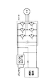
図3は、本発明における電力変換装置の回路図を示している。電源10aの負極と、電源10bの負極が共通負極母線15に接続されている。ここで、電源10bは充放電が可能ないわゆる二次電池であり、電源10aは放電が可能な燃料電池である。ただし、本発明はこれに限られるものではなく、電源10aも二次電池としてもよい。ここでは主に電源10aから、電源10bへの充電を行う場合を説明する。
Hereinafter, embodiments of the present invention will be described in detail with reference to the drawings.
First Embodiment FIG. 3 shows a circuit diagram of a power converter according to the present invention. The negative electrode of the power supply 10a and the negative electrode of the power supply 10b are connected to the common
共通負極母線15とモータ20の各相端子間には、一般的に知られているインバータの下アームと同様に、半導体スイッチ107a,108a,109aとダイオード107b,108b,109bの組が接続される。電源10aの正極母線14とモータ20の各相端子間とは、双方向の導通を制御可能な半導体スイッチ101a/101b,102a/102b,103a/103bでそれぞれ接続する。また、電源10bの正極母線16とモータ20の各相端子間にも、双方向の導通を制御可能な半導体スイッチ104a/104b,105a/105b,106a/106bをそれぞれ接続する。電源10aの正極母線14と共通負極母線15の間には平滑コンデンサ12を設け、電源10bの正極母線16と共通負極母線15の間にも平滑コンデンサ13を設ける。
A pair of
電力変換器30は、共通負極母線と電源10aの正極母線と電源10bの正極母線、以上の3つの電位をもとに、モータに印加する電圧を生成する直流-交流電力変換器である。各相に設けられた半導体スイッチで構成されるU相、V相、W相のスイッチ群30U、30V、30Wが、交流モータの各相に出力する電圧を生成するスイッチ手段であり、これらの電位のなかから択一的に接続し、その接続する時間の割合を変化させることで、モータに必要な電圧を供給する。
The
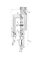
図2を用いて、電力変換器の制御装置40の構成を説明する。41は、外部より与えられるトルク指令Te*とモータ回転速度ωと電源10aから電源10bへの充電量を指令する電源10bの電力指令値Pb*から、交流モータのd軸電流の指令値id*とq軸電流の指令値iq*、分配電力目標値rto_pa、d軸電圧補正値vd_0*、q軸電圧補正値vq_0*を演算するトルク制御手段である。(モータ電流指令値生成手段に相当する)手段41では、予め作成されたTe*、ω、Pb*の3つの要素を軸とした3次元のマップ(即ち、これら3要素の数値を所定の式に代入して予め演算された下記指令値を含むマップ)を参照し、モータ電流指令値id*,iq*、電力配分比率指令値rto_pa、補正電圧指令値vd_0*,vq_0*を出力する(第1、第2の発明に相当)。 The configuration of the power converter control device 40 will be described with reference to FIG. 41 is a command value id * of the d-axis current of the AC motor from a torque command Te *, a motor rotation speed ω, and a power command value Pb * of the power supply 10b that commands a charge amount from the power supply 10a to the power supply 10b. And q-axis current command value iq *, distributed power target value rto_pa, d-axis voltage correction value vd_0 *, and q-axis voltage correction value vq_0 *. In the means 41 (corresponding to the motor current command value generating means), a three-dimensional map with the three elements of Te *, ω, and Pb * created in advance as axes (that is, the numerical values of these three elements are used as a predetermined formula) (Refer to a map including the following command value calculated in advance) and output motor current command value id *, iq *, power distribution ratio command value rto_pa, corrected voltage command value vd_0 *, vq_0 * 1 and corresponding to the second invention).
トルク制御手段41を詳細に説明する。通常モータをトルク制御する場合には、トルク指令Te*とモータ回転速度ωに応じてモータに流す電流を決定する必要があるが、本実施例ではベクトル制御を用いており、トルクと回転速度に応じて適切な電流(d軸電流指令値id*、q軸電流指令値iq*)を流すことによりモータに所定のトルクを与えている。 The torque control means 41 will be described in detail. When controlling the torque of a normal motor, it is necessary to determine the current that flows to the motor in accordance with the torque command Te * and the motor rotational speed ω, but in this embodiment, vector control is used. Accordingly, a predetermined torque is applied to the motor by supplying appropriate current (d-axis current command value id *, q-axis current command value iq *).
本実施例ではあらかじめ実験等で得られたトルク指令Te*とモータ回転速度ωに対応するd軸電流指令値id*、q軸電流指令値iq*を図19の1枚に示すようなマップとして備える。さらに本実施例では、上述のように、上記マップをさらに電力指令値Pb*に対応したマップとして複数備えるものであり、即ち3次元マップを構成する。ここで、電力指令値Pb*に対応した複数のマップはあらかじめ実験等で得られたトルク指令Te*とモータ回転速度ωに対応するd軸電流指令値id*、q軸電流指令値iq*に基づいて演算されたものであって、具体的にはPb*0のときのid*にPb*1のときはvd_0*がPb*1/id*となり、vq_0*は常に0となるように設定されている。 In the present embodiment, the torque command Te * obtained in advance through experiments or the like, the d-axis current command value id * and the q-axis current command value iq * corresponding to the motor rotation speed ω are mapped as a map shown in FIG. Prepare. Further, in the present embodiment, as described above, a plurality of maps are provided as maps corresponding to the power command value Pb *, that is, a three-dimensional map is configured. Here, a plurality of maps corresponding to the electric power command value Pb * are represented by a torque command Te * obtained in advance through experiments or the like, a d-axis current command value id * and a q-axis current command value iq * corresponding to the motor rotation speed ω. Specifically, it is calculated so that vd_0 * becomes Pb * 1 / id * and vq_0 * is always 0 when Pb * 1 is set to id * when Pb * 0 Has been.
つまり、Pb*=0のとき、Te1、ω1に対応した箇所には
id*=id*1-1、iq*=iq*1-1、vd_0*=0、vq_0*=0が格納されており、
Pb*=Pb*1のとき、Te1、ω1に対応した箇所には
id*=id*1-1、iq*=iq*1-1、vd_0*=Pb*1/id*1-1、vq_0*=0が格納されることになる。
In other words, when Pb * = 0, id * = id * 1-1, iq * = iq * 1-1, vd_0 * = 0, vq_0 * = 0 are stored in the locations corresponding to Te1 and ω1. ,
When Pb * = Pb * 1, the locations corresponding to Te1 and ω1 have id * = id * 1-1, iq * = iq * 1-1, vd_0 * = Pb * 1 / id * 1-1, vq_0 * = 0 is stored.
さらに、Pb*=0のとき、Te0、ω0(モータトルク指令値またはモータ回転速度のいずれかが0或いは0近傍である場合に相当)に対応した箇所には、
id*=0、iq*=0、vd_0*=0、vq_0*=0が格納されているのに対し、
Pb*=Pb*1のとき、Te0、ω0に対応した箇所には、
id*=X(後述する)、iq*=0、vd_0*=Pb*1/X、vq_0*=0が格納されている。
Furthermore, when Pb * = 0, Te0, ω0 (corresponding to either the motor torque command value or the motor rotation speed being 0 or near 0),
Where id * = 0, iq * = 0, vd_0 * = 0, vq_0 * = 0 are stored,
When Pb * = Pb * 1, the locations corresponding to Te0 and ω0 are
id * = X (described later), iq * = 0, vd_0 * = Pb * 1 / X, and vq_0 * = 0 are stored.
ここで、常にvq_0*=0としたのは、トルク指令Te*とモータ回転速度ωのときにiq*を流すことはできないためであって、本実施例では計算を簡略化するために、常にvq_0*=0としているが、モータが回転しているときであれば、iq*を流すことができるので、対応したvq_0*を設定することも可能である。さらに、本実施例では、Pb*=0以外のマップには分配電力目標値rto_pa=1となる数値を入力してある。つまりPb*が0以上の場合は、後述するrto_pa、rto_pbの関係はrto_pa=1とする必要があるからである。 Here, the reason why vq_0 * = 0 is always set is that iq * cannot flow when the torque command Te * and the motor rotational speed ω. In this embodiment, in order to simplify the calculation, Although vq_0 * = 0, since iq * can be flowed when the motor is rotating, a corresponding vq_0 * can be set. Furthermore, in the present embodiment, a numerical value that is the distributed power target value rto_pa = 1 is input to a map other than Pb * = 0. That is, when Pb * is 0 or more, the relationship between rto_pa and rto_pb described later needs to be rto_pa = 1.
図20は、トルク制御手段41の処理を示すフローチャートである。このフローチャートに示すように、3次元マップの参照によって、トルク指令の状態によっては演算Aを省略することが可能となる。トルク制御手段41は、図20に示すようなフローチャートに従ってid*,iq*,rto_pa,vq_0*,vd_0*を生成する。図に示すように、入力されたトルク指令Te*が0かそれ以外かを判定し、トルク指令が0の場合には、演算Aを行う。この演算は、モータが0トルクの状態で電源aと電源bの電力配分を高効率で行うための指令値演算であり、モータの銅損を最小化するように指令値が生成される。 FIG. 20 is a flowchart showing the processing of the torque control means 41. As shown in this flowchart, calculation A can be omitted depending on the state of the torque command by referring to the three-dimensional map. The torque control means 41 generates id *, iq *, rto_pa, vq_0 *, vd_0 * according to the flowchart shown in FIG. As shown in the figure, it is determined whether the input torque command Te * is 0 or not. If the torque command is 0, calculation A is performed. This calculation is a command value calculation for performing power distribution of the power source a and the power source b with high efficiency while the motor is at 0 torque, and the command value is generated so as to minimize the copper loss of the motor.
また、キャリア周波数値fcが一定値の場合には、Pb*とLdを軸とする二次元マップを演算1に基づいてあらかじめ作成し、この二次元マップを参照することによって指令値を生成しても良い。さらに、Ldが一定値、あるいはその変動が小さい場合にはLdを一定とし、Pb*のみを変数として指令値を生成しても良い。トルクが0以外の場合には、上述したように予め実験で求められた三次元マップを参照し、モータの運転状態に応じた指令値を生成する。
When the carrier frequency value fc is a constant value, a two-dimensional map with Pb * and Ld as axes is created in advance based on
42は電流・電力制御手段であり、ここでは、d軸電流指令値id*、q軸電流指令値iq*とd軸電流値id、q軸電流値iqから、これらを一致させるための電流制御を行うとともに、電源10aと10bから供給される電力の分配目標値(rto_pa、rto_pb)を用いて、電力制御を行う。電源10aと10bから供給される電力の分配目標値(rto_pa、rto_pb)はさらに上位のコントローラから供給されるものであり、システム全体の燃費、負担などを鑑みて決定されている。
電力の分配目標値は、補正電圧値vd_0*,vq_0*が0のときの、電源10aと電源10bの電力の比率を意味しており、電力の分配目標値rto_pa、rto_pbは次の関係をもつ。
rto_pa + rto_pb = 1
このため、一方の電力分配目標値が得られれば、上の関係から、もう一方の電力分配目標値を求めることができる。つまり、rto_paのみ上位コントローラから与えられれば後述の分電圧指令の演算が可能である。なお、Pb*=0のときは上位のコントローラから送信されるrto_paに従うことになる。一方、Pb*=0以外のときは前述のトルク制御手段41から送信されるrto_pa=1に従うことになる。つまり、電流・電力制御手段42としては上位コントローラもしくはトルク制御手段41から送信されるrto_paにしたがって分電圧指令の演算が可能となる。
The power distribution target value means the ratio of power between the power supply 10a and the power supply 10b when the correction voltage values vd_0 * and vq_0 * are 0. The power distribution target values rto_pa and rto_pb have the following relationship: .
rto_pa + rto_pb = 1
For this reason, if one power distribution target value is obtained, the other power distribution target value can be obtained from the above relationship. In other words, if only rto_pa is given from the host controller, a voltage division command described later can be calculated. When Pb * = 0, it follows rto_pa transmitted from the host controller. On the other hand, when Pb * = 0 is not satisfied, rto_pa = 1 transmitted from the torque control means 41 is followed. In other words, the current / power control means 42 can calculate a divided voltage command according to rto_pa transmitted from the host controller or torque control means 41.
この電流・電力制御手段42の詳細について、図11を用いて説明する。電流制御器42aでは、id*、iq*にid、iqが追従するように、それぞれPI制御によるフィードバック制御を行って、d軸電圧指令値vd*、q軸電圧指令値vq*を出力する。id、iqは3相/dq変換手段48によりU相電流iu、V相電流ivから求められる。
dq/3相変換器42bは、dq軸電圧を3相電圧指令に変換するdq/3相電圧変換手段であり、dq軸電圧指令値vd*、vq*を入力とし、U相電圧指令値vu*、V相電圧指令値vv*、W相電圧指令値vw*を出力する。乗算器42cでは、vu*、vv*、vw*に、それぞれrto_paを乗じて、電源10a側の電圧指令値であるvu_a、vv_a、vw_aを演算する(以下、電源10aから生成する電圧の指令を電源10a分電圧指令、電源10bから生成する電圧の指令を電源10b分電圧指令と記す)。
vu_a = vu* ・ rto_pa
vv_a = vv* ・ rto_pa
vw_a = vw* ・ rto_pa
また、vd_0*,vq_0*は、dq/3相変換器42dによってU相補正電圧値vu_0*,V相補正電圧値 vv_0*, W相補正電圧値vw_0*に変換される。得られたvu_0*, vv_0*, vw_0*と、vu_a,vv_a,vw_aを各相それぞれ加算器42eで加算し、電源10a側の電圧指令値vu_a*、vv_a*、vw_a*を出力する。
vu_a* = vu_a + vu_0*
vv_a* = vv_a + vv_0*
vw_a* = vw_a + vw_0*
一方、電源10b側の電圧指令値は、モータ電流制御の制御電圧から得られた電圧指令値
vu*、vv*、vw*から、電源10a側の電圧指令値値vu_a*、vv_a*、vw_a*を減算器42fで減算して求める。
vu_b* = vu* - vu_a*
vv_b* = vv* - vv_a*
vw_b* = vw* - vw_a*
Details of the current / power control means 42 will be described with reference to FIG. The
The dq / 3-phase converter 42b is dq / 3-phase voltage conversion means for converting the dq-axis voltage into a three-phase voltage command, and receives the dq-axis voltage command values vd * and vq * as input, and the U-phase voltage command value vu. *, V phase voltage command value vv *, W phase voltage command value vw * are output. The
vu_a = vu * ・ rto_pa
vv_a = vv * ・ rto_pa
vw_a = vw * ・ rto_pa
Further, vd_0 * and vq_0 * are converted into a U-phase correction voltage value vu_0 *, a V-phase correction voltage value vv_0 *, and a W-phase correction voltage value vw_0 * by the dq / 3-
vu_a * = vu_a + vu_0 *
vv_a * = vv_a + vv_0 *
vw_a * = vw_a + vw_0 *
On the other hand, the voltage command value on the power supply 10b side is obtained from the voltage command values vu *, vv *, vw * obtained from the control voltage of the motor current control, and the voltage command value values vu_a *, vv_a *, vw_a * on the power supply 10a side. Is subtracted by a subtractor 42f.
vu_b * = vu *-vu_a *
vv_b * = vv *-vv_a *
vw_b * = vw *-vw_a *
図2に戻るが符号45は、電源10aの電圧Vdc_a、電源10bの電圧Vdc_bを入力し正規格化した電圧指令である瞬時変調率指令mu_a*、mu_b*、mv_a*、mv_b*、mw_a*、mw_b*を生成する変調率演算手段である。46は、瞬時変調率指令にPWMを行う前の処理を行い最終的な瞬時変調率指令mu_a_c*、mu_b_c *、mv_a_c *、mv_b_c *、mw_a_c *、mw_b_c *を生成する変調率補正手段である。47は、最終的な瞬時変調率指令に基づいて電力変換器30の各スイッチをオン/オフするPWMパルスを生成するPWMパルス生成手段である。以下、変調率演算手段45、変調率補正手段46、PWMパルス生成手段47を図4〜10を用いて詳細に説明する。
Returning to FIG. 2,
図4は、図2の一部のブロックを抜き出した構成を示す図でああり、図5は、図4の各手段で行う演算をフローチャートで示したものである。以下の説明は、U相についてのみ行うが、V相、W相についても全く同様の操作を行う。
変調率演算手段45
変調率演算手段45は図5に示す演算2を行う。U相の電源10a分電圧指令vu_a*、電源10b分電圧指令vu_b*をそれぞれの直流電圧の半分の値で正規化することで電源10a分瞬時
変調率指令mu_a*、電源10b分瞬時変調率指令mu_b*を求める。
mu_a*=vu_a*/(Vdc_a/2)
mu_b*=vu_b*/(Vdc_b/2)
FIG. 4 is a diagram showing a configuration in which some of the blocks in FIG. 2 are extracted, and FIG. 5 is a flowchart showing operations performed by each means in FIG. The following description is performed only for the U phase, but the same operation is performed for the V phase and the W phase.
Modulation rate calculation means 45
The modulation factor calculation means 45 performs
mu_a * = vu_a * / (Vdc_a / 2)
mu_b * = vu_b * / (Vdc_b / 2)
変調率補正手段46(第6の発明に相当)
変調率補正手段46は図5に示す演算3を行う。この詳細は図15のフローチャートに示している。この演算では、得られた変調率を出力するために、PWM周期の時間幅を配分する。まず、電源電圧Vdc_a、Vdc_bと、rto_paから次のma_offset0, mb_offset0を演算する。ここでrto_pbは、前述の式をもとに演算する。
rto_pb = 1 - rto_pa
The modulation rate correction means 46 performs
rto_pb = 1-rto_pa
次に、図15のフローチャートに従って、電源電圧Vdc_aとVdc_bの大きさを比較する。比較後、電圧補正値を出力するために確保すべき変調率振幅offset_d0を演算する。この
とき、電源電圧の小さいほうはoffset_d0が大きくなり、この変調率振幅を確保するため
に、先に電源電圧の大きさを比較している。また、本実施例ではvq_0*=0とし、offset_d0としては、vd_0*を出力するために必要な変調率振幅を求める。
Vdc_a < Vdc_b であるとき
Vdc_a > Vdc_b であるとき
When Vdc_a <Vdc_b
When Vdc_a> Vdc_b
offset_d0を演算した後、前もって演算したma_offset0とmb_offset0の大きさを比較し、小さいほうにoffset_d0を加算し、変調率振幅を出力できるようにオフセット値を確保する。ここで、ma_offset0とmb_offset0は次のような関係を持つ。
ma_offset0 + mb_offset0 = 1
よって、ma_offset0 > mb_offset0 は次のように表すことができる。
ma_offset0 > 1/2
この条件を満たす結果(真)であれば、mb_offset0が小さく、以下のようにoffset_d0をmb_offset0に加算する。
mb_offset = mb_offset0 + offset_d0
また、mb_offsetは1を上限とし、この上限値を持つリミッタを通過させ、リミッタの出力mb_offset*を得る。一方のma_offset*は、次の式から演算する。
ma_offset* = 1 - mb_offset*
分岐の条件を満たさない結果(偽)である場合、フローチャートに示したように、aとbを入れ替えて上記演算を実行することになる。
After computing offset_d0, the magnitudes of ma_offset0 and mb_offset0 computed in advance are compared, offset_d0 is added to the smaller one, and an offset value is secured so that the modulation factor amplitude can be output. Here, ma_offset0 and mb_offset0 have the following relationship.
ma_offset0 + mb_offset0 = 1
Therefore, ma_offset0> mb_offset0 can be expressed as follows.
ma_offset0> 1/2
If the result satisfies this condition (true), mb_offset0 is small, and offset_d0 is added to mb_offset0 as follows.
mb_offset = mb_offset0 + offset_d0
Also, mb_offset has an upper limit of 1, and passes through a limiter having this upper limit value, and obtains an output mb_offset * of the limiter. One ma_offset * is calculated from the following equation.
ma_offset * = 1-mb_offset *
When the result does not satisfy the branch condition (false), as shown in the flowchart, a and b are exchanged and the above calculation is executed.
電源10a分瞬時変調率指令mu_a*、電源10b分瞬時変調率指令mu_b*は、オフセット値ma_offset* , mb_offset*を用いて次のように補正演算を行い、mu_a_c*,mu_b_c*を出力する。
mu_a_c* = mu_a* + ma_offset* - 1
mu_b_c* = mu_b* + mb_offset* - 1
このような補正演算を行うことで、三角波比較時に変調率指令を出力できる時間を確保することができる。例えば、rto_pa = 1 であるとき、mb_offset0 =0 となるが、mb_offsetは、offset_d0が加算され、d軸補正電圧を出力するための時間が確保できる。図16は、このときのmu_b_c*とmb_offsetを示したものであり、mu_b*にmb_offsetを加算する事で、三角波比較が実現できることがわかる(第6の発明の効果に相当)。
The instantaneous modulation rate command mu_a * for the power supply 10a and the instantaneous modulation rate command mu_b * for the power supply 10b are corrected as follows using the offset values ma_offset * and mb_offset * and output mu_a_c * and mu_b_c *.
mu_a_c * = mu_a * + ma_offset *-1
mu_b_c * = mu_b * + mb_offset *-1
By performing such correction calculation, it is possible to secure a time during which the modulation rate command can be output during the triangular wave comparison. For example, when rto_pa = 1, mb_offset0 = 0, but offset_d0 is added to mb_offset, and a time for outputting the d-axis correction voltage can be secured. FIG. 16 shows mu_b_c * and mb_offset at this time, and it can be seen that triangular wave comparison can be realized by adding mb_offset to mu_b * (corresponding to the effect of the sixth invention).
PWMパルス生成手段47(演算4)
PWMパルス生成手段47は図5に示す演算4の処理を行う。図6において、電源10a用キャリアは、電源10aの電圧Vdc_aから電圧パルスを出力するために、各スイッチを駆動するPWMパルスを生成するための三角波キャリアであり、同様に、電源10b用キャリアとして三角波を設ける。これら二つの三角波キャリアは、上限+1、下限―1の値をとり、180度の位相差を持つ。ここでは、U相の各スイッチを駆動する信号を、図7をもとに次のようにおく。
A:電源10aから出力端子の方向へ導通するスイッチの駆動信号
B:出力端子から負極の方向へ導通するスイッチの駆動信号
C:出力端子から電源10aの方向へ導通するスイッチの駆動信号
D:電源10bから出力端子の方向へ導通するスイッチの駆動信号
E:出力端子から電源10bの方向へ導通するスイッチの駆動信号
まず、電源10aから電圧パルスを出力する際のパルス生成方法について述べる。電源10aからPWMパルスを出力する際に、Aをオンする必要がある。正極と正極の間に電位差があり、Vdc_a>Vdc_bである時、AとEがともにオンすると、正極間を短絡する電流が流れることになる。例えば、同時にAをオンからオフへ、Eをオフからオンへ信号を切り換えた場合に、Aが完全にオフするまでに時間を要するため、Eのオン時と重なり、ともにオンする時間が生じ、短絡電流が流れ、この経路に設置された半導体スイッチの発熱量が増加する。このような発熱の増加を予防するために、駆動信号AとEがともにオフする時間を経過した後に、A、Eをオフからオンへ切り換えるようにする。このように駆動信号に短絡防止時間(デッドタイム)を付加したパルス生成を行う。このAとEの駆動信号にデッドタイムを付加するのと同様に、EとCにデッドタイムを付加し、さらに、正極と負極の短絡防止のためには、AとB、EとBにデッドタイムを付加する。
PWM pulse generation means 47 (calculation 4)
The PWM pulse generating means 47 performs the processing of the
A: Switch drive signal conducting from the power supply 10a to the output terminal B: Switch drive signal conducting from the output terminal to the negative electrode C: Switch drive signal conducting from the output terminal to the power supply 10a D: Power supply Switch drive signal conducting from 10b to output terminal E: Switch drive signal conducting from output terminal to power supply 10b First, a pulse generation method for outputting voltage pulses from the power supply 10a will be described. When outputting a PWM pulse from the power supply 10a, it is necessary to turn on A. When there is a potential difference between the positive electrode and the positive electrode and Vdc_a> Vdc_b, when both A and E are turned on, a current that short-circuits between the positive electrodes flows. For example, when A is switched from on to off at the same time and E is switched from off to on, it takes time for A to completely turn off. A short-circuit current flows, and the amount of heat generated by the semiconductor switch installed in this path increases. In order to prevent such an increase in heat generation, A and E are switched from OFF to ON after a time during which both the drive signals A and E are turned off. In this way, pulse generation is performed by adding a short-circuit prevention time (dead time) to the drive signal. Similar to adding dead time to the drive signals of A and E, dead time is added to E and C, and in order to prevent a short circuit between the positive and negative electrodes, dead to A and B and E and B. Add time.
図8を用いて、AとEの駆動信号にデッドタイムを付加する方法を以下に説明する。デッドタイムを付加した駆動信号生成を行うため、mu_a_c*からデッドタイム分オフセットしたmu_a_c_up*,mu_a_c_down*を次のように求める。
mu_a_c_up* = mu_a_c* + Hd
mu_a_c_down* = mu_a_c* − Hd
ここで、Hdは三角波の振幅(底辺から頂点まで)Htrと周期Ttr、デッドタイムTdから次のように求める。
Hd = 2Td・Htr/Ttr
キャリアとmu_a_c*,mu_a_c_up*,mu_a_c_down*の比較を行って、AとEのスイッチの駆動信号を次のルールに従って求める。
mu_a_c_down* ≧電源10a用キャリア ならば A = ON
mu_a_c* ≦電源10a用キャリア ならば A = OFF
mu_a_c* ≧電源10a用キャリア ならば E = OFF
mu_a_c_up* ≦電源10a用キャリア ならば E = ON
このように、駆動信号を生成することで、AとEの間にはTdのデッドタイムを設けることができ、正極間の短絡を防止することができる。
A method for adding dead time to the A and E drive signals will be described below with reference to FIG. In order to generate a drive signal with a dead time added, mu_a_c_up * and mu_a_c_down * offset from the mu_a_c * by the dead time are obtained as follows.
mu_a_c_up * = mu_a_c * + Hd
mu_a_c_down * = mu_a_c * − Hd
Here, Hd is obtained from the amplitude of the triangular wave (from the base to the apex) Htr, the period Ttr, and the dead time Td as follows.
Hd = 2Td · Htr / Ttr
The carrier and mu_a_c *, mu_a_c_up *, mu_a_c_down * are compared, and the drive signals for the A and E switches are obtained according to the following rules.
If mu_a_c_down * ≧ carrier for power supply 10a, A = ON
If mu_a_c * ≤ carrier for power supply 10a, A = OFF
If mu_a_c * ≥ carrier for power supply 10a, E = OFF
mu_a_c_up * ≤ Carrier for power supply 10a E = ON
Thus, by generating the drive signal, a dead time of Td can be provided between A and E, and a short circuit between the positive electrodes can be prevented.
また、電源10bから電圧パルスを出力する際のパルス生成方法は、電源10aの場合と同様であり、次のmu_b_c_up*,mu_b_c_down*を求め、電源10b用キャリアとの比較を行う(図9)。
mu_b_c_up* = mu_b_c* + Hd
mu_b_c_down* = mu_b_c* − Hd
DとCのスイッチの駆動信号を次のルールに従って求める。
mu_b_c_down* ≧電源10b用キャリア ならば D = ON
mu_b_c* ≦電源10b用キャリア ならば D = OFF
mu_b_c* ≧電源10b用キャリア ならば C = OFF
mu_b_c_up* ≦電源10b用キャリア ならば C = ON
このようにして、DとCの間にもTdのデッドタイムを設けることができ、正極間の短絡を防止することができる。
駆動信号Bは、生成された駆動信号EとCのANDから生成する。
B=E・C
EはAとの間にデッドタイムが付加した駆動信号であり、CはDとの間にデッドタイムが付加した駆動信号である。このため、BをEとCのANDから生成することで、BとA、BとEにもデッドタイムを生成することができる。デッドタイムが付加されたパルス生成の例を図10に示す。このようにして生成されたPWMパルスをもとに、電力変換器の各スイッチをオン・オフ駆動し、出力電圧パルスを生成する。周期毎に、電源10aの電圧Vdc_aから生成された電圧パルスと、電源10bの電圧Vdc_bから生成された電圧パルスとの平均をとると、元の3相電圧指令値vu*、vv*、vw*を実現する電圧パルスが生成されていることになる。
Further, the pulse generation method when outputting a voltage pulse from the power supply 10b is the same as that of the power supply 10a, and the following mu_b_c_up * and mu_b_c_down * are obtained and compared with the carrier for the power supply 10b (FIG. 9).
mu_b_c_up * = mu_b_c * + Hd
mu_b_c_down * = mu_b_c * − Hd
The drive signals for the D and C switches are obtained according to the following rules.
If mu_b_c_down * ≥ carrier for power supply 10b, D = ON
If mu_b_c * ≤ carrier for power supply 10b, D = OFF
If mu_b_c * ≥ carrier for power supply 10b, C = OFF
If mu_b_c_up * ≤ carrier for power supply 10b, C = ON
In this way, a dead time of Td can be provided between D and C, and a short circuit between the positive electrodes can be prevented.
The drive signal B is generated from the AND of the generated drive signals E and C.
B = E ・ C
E is a drive signal with a dead time added to A, and C is a drive signal with a dead time added to D. Therefore, by generating B from the AND of E and C, it is possible to generate dead time for B and A and B and E as well. An example of pulse generation with a dead time added is shown in FIG. Based on the PWM pulse generated in this way, each switch of the power converter is driven on and off to generate an output voltage pulse. Taking the average of the voltage pulse generated from the voltage Vdc_a of the power supply 10a and the voltage pulse generated from the voltage Vdc_b of the power supply 10b for each period, the original three-phase voltage command values vu *, vv *, vw * Thus, a voltage pulse that realizes is generated.
交流モータの電力Pe(有効電力)は、dq軸の電圧vd,vqと電流id,iqを用いると次のように表せる。
Pe = vd ・ id + vq ・ iq
この式からもわかるように、id,iqが0では電力は0であり、また、idもしくはiqが0でないとしても、同じ軸の電圧が0であると電力は0である。また、0でないとしても、積をとる一方の値が小さい場合には、電力を演算すると小さな値になる。
電力の分配目標値を用いることで電源10aと電源10bの電力の配分を操作することが可能であるが、従来の電力変換装置ではモータ電力が0、もしくは極めて小さい場合には、電源10aから電源10bへの電力の移動が困難になる。
The power Pe (active power) of the AC motor can be expressed as follows using the voltages vd and vq on the dq axis and the currents id and iq.
Pe = vd, id + vq, iq
As can be seen from this equation, when id and iq are 0, the power is 0. Even when id or iq is not 0, the power is 0 when the voltage on the same axis is 0. Even if it is not 0, if one of the product values is small, the power is calculated to be a small value.
It is possible to operate the power distribution between the power source 10a and the power source 10b by using the power distribution target value. However, when the motor power is zero or very small in the conventional power conversion device, the power source from the power source 10a Power transfer to 10b becomes difficult.
本発明によるトルク制御器によって出力された電流指令値と補正電圧値を用いることで、例として以下のような動作が行われる。モータトルク指令値0がトルク制御器に入力され、モータ電流指令値としてid*=0,iq*=0によって、このトルク指令値0を実現できるような場合でも、Pb*がトルク制御器に入力されると、それに応じた指令値マップを参照し、トルク分電流であるiq*を0、電流指令値id*、補正電圧値vd_0*(vq_0*=0)を出力し、電力配分比は電力配分比rto_pa=1(rto_pb=0)を出力する(これは第3の発明のトルクを生じない電流指令値、第4の発明のd軸電流への適用例である)。
このとき、Pb*が負の値、すなわち充電を指示する電力指令である場合、電源10bの充電電力分を電源10aから供給する。電力配分比rto_pa=1,rto_pb=0であるから、電源10aはvd*にvd_0*を加算して出力しており、一方の電源10bは、-vd_0*分を出力することになり、電源10aの電力Paと電源10bのPbを、電圧・電流指令値を用いて表せば、次のようになる。
Pa = (vd* + vd_0*)・id* + vq*・iq*
Pb = -vd_0*・id*
これらの式が示すように、vd_0*とid*が同符号であれば、電源10aはvd_0*によってモータ電力よりも大きな電力を出力し、電源10bを充電することになる。
以上のように、モータのトルク指令値が0であっても、トルク指令制御器による電流指令値と補正電圧指令値を出力し、これらに基づいて電圧パルスを生成することによって、他方の電源への電力の移動が可能になる。また、モータ速度が0であっても、同様に電力の移動が可能である。
By using the current command value and the correction voltage value output by the torque controller according to the present invention, the following operation is performed as an example. Even when the motor
At this time, if Pb * is a negative value, that is, a power command for instructing charging, the charging power for the power source 10b is supplied from the power source 10a. Since power distribution ratios rto_pa = 1 and rto_pb = 0, the power supply 10a outputs vd_0 * added to vd *, and one power supply 10b outputs -vd_0 *, and the power supply 10a If the power Pa and Pb of the power source 10b are expressed using voltage / current command values, the following is obtained.
Pa = (vd * + vd_0 *) ・ id * + vq * ・ iq *
Pb = -vd_0 * ・ id *
As these formulas show, if vd_0 * and id * have the same sign, the power supply 10a outputs power larger than the motor power by vd_0 * and charges the power supply 10b.
As described above, even if the torque command value of the motor is 0, the current command value and the correction voltage command value by the torque command controller are output, and the voltage pulse is generated based on these values, so that the other power source is supplied. The power can be transferred. Further, even when the motor speed is 0, the power can be moved similarly.
模擬実験による本例の結果を図17、18に示した。図18はモータ電流id,iqを示しており、iqが0に制御されており、モータトルクは0になる。また、図17は各電源電力Pa,Pbを示しており、時刻Xの点の前では、電源電力指令値Pb*は0がトルク制御器に入力され、補正電圧指令値も0が出力されている。時刻X以降で負の電力指令値がトルク制御器に入力され、トルク制御器は補正電圧指令値vd_0*を出力し、その結果、電源間での電力移動を実現できていることがわかる。また、補正電圧指令値に前記配分電圧指令値を加算して電圧指令値を求めているため、図17のような変動が比較的少ない良好な波形で電力移動が達成できる。 The results of this example from a simulation experiment are shown in FIGS. FIG. 18 shows motor currents id and iq, where iq is controlled to 0 and the motor torque becomes 0. FIG. 17 shows each power source power Pa, Pb. Before the point of time X, the power source power command value Pb * is input to the torque controller, and the correction voltage command value is also output to 0. Yes. After time X, a negative power command value is input to the torque controller, and the torque controller outputs a corrected voltage command value vd_0 *. As a result, it can be seen that power transfer between the power sources can be realized. Further, since the voltage command value is obtained by adding the distribution voltage command value to the correction voltage command value, power transfer can be achieved with a good waveform with relatively little fluctuation as shown in FIG.
また、本発明を電源に燃料電池とバッテリを備えるハイブリッド電気自動車に適用すれば、DC/DCコンバータなどの直流電力の電力変換器を用いずに、電力変換器とモータを介したバッテリ充電が可能になるため、車両駆動の電気システムが簡素な構成になり、小型・軽量化が図れる。なお、本発明では、補正電圧指令値をd軸電圧として出力しているが、iq*が0でない場合には、q軸電圧を補正電圧指令値に用いて、前述のような電力の移動を実現することも可能である。 Moreover, if the present invention is applied to a hybrid electric vehicle having a fuel cell and a battery as a power source, a battery can be charged via a power converter and a motor without using a DC power converter such as a DC / DC converter. Therefore, the electric system for driving the vehicle has a simple configuration and can be reduced in size and weight. In the present invention, the correction voltage command value is output as the d-axis voltage. However, when iq * is not 0, the q-axis voltage is used as the correction voltage command value to move the power as described above. It can also be realized.
つぎに、モータトルク0の場合のidの決定方法を示す。このような条件におけるトルク制御手段41の制御を説明する。トルク制御手段41は、トルク指令値Te*,回転数ω,電源bの電力指令値Pb*から、最適な電流指令値と補正電圧指令値を生成するブロックである。この制御においては、トルク0のときに電源10aから電源10b、あるいは電源10bから電源10aへの充電を効率よく行うための指令値生成方法に特徴がある。 Next, a method for determining id when the motor torque is zero will be described. The control of the torque control means 41 under such conditions will be described. The torque control means 41 is a block that generates an optimal current command value and a corrected voltage command value from the torque command value Te *, the rotational speed ω, and the power command value Pb * of the power source b. This control is characterized by a command value generation method for efficiently charging from the power source 10a to the power source 10b or from the power source 10b to the power source 10a when the torque is zero.
充電を効率よく行うために、まずモータの損失の計算方法について述べる。モータの損失には鉄損Wi、銅損Wc、および機械損Wmがある。このなかで銅損Wcは、
Wc = R * √(id^2 + iq^2) (1)
より求める。特に、トルクが0の場合にはモータのq軸方向のトルク(磁石トルク)をゼロにすべくiq は0とするため、銅損は
Wc = R * √id^2 (2)
となる。また、idにリップル成分idh(実効値)が乗っている場合、この損失は
Wc = R * id^2 + R * idh^2 (3)
となる。ここで、永久磁石同期電動機の電圧、電流には以下の関係がある。
vd = (R + pLd)id - Lq*ωe*iq (4)
vq = (R + pLq)iq + Ld*ωe*id +ωe*φ (5)
vd,vqはモータ20のd軸q軸電圧、pは微分演算子、ωeは電気角周波数,φは電気子鎖交磁束数である。ここで、定常状態、トルク0の状態ではiq = 0であり、RidはpLdに比べて小さいためゼロとすると、
vd = pLdid (6)
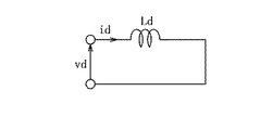
vq = Ld*ωe*id +ωe*φ (7)
となる。従って、d軸の等価回路は図22のようになる。ここで、本構成では、
vd_a* = vd_a + vd_0* (8)
vd_b* = vd* - vd_a* (9)
なる指令値を生成するため、vdは図23(キャリアと電圧・電流のタイミングチャート)のように2値をとり、このような二値のvdを図22の等価回路に印加した場合、idは図のようにリップル成分を持つ。この値は(10)式で与えられる。
Wc = R * √ (id ^ 2 + iq ^ 2) (1)
Ask more. In particular, when the torque is 0, iq is 0 to reduce the torque in the q-axis direction of the motor (magnet torque) to zero, so the copper loss is
Wc = R * √id ^ 2 (2)
It becomes. Also, if the ripple component idh (effective value) is on id, this loss is
Wc = R * id ^ 2 + R * idh ^ 2 (3)
It becomes. Here, the voltage and current of the permanent magnet synchronous motor have the following relationship.
vd = (R + pLd) id-Lq * ωe * iq (4)
vq = (R + pLq) iq + Ld * ωe * id + ωe * φ (5)
vd and vq are d-axis and q-axis voltages of the
vd = pLdid (6)
vq = Ld * ωe * id + ωe * φ (7)
It becomes. Therefore, the equivalent circuit of the d axis is as shown in FIG. Here, in this configuration,
vd_a * = vd_a + vd_0 * (8)
vd_b * = vd *-vd_a * (9)
Vd takes a binary value as shown in FIG. 23 (carrier and voltage / current timing chart), and when such a binary vd is applied to the equivalent circuit of FIG. It has a ripple component as shown. This value is given by equation (10).
従って、銅損は(3)式を元に、
となる。この構成によってキャリア周波数やモータインダクタンスが変化する場合であっても正確に銅損を計算でき、損失の最適化を精度よく行うことができる。
Therefore, copper loss is based on equation (3).
It becomes. With this configuration, even when the carrier frequency and the motor inductance change, the copper loss can be accurately calculated, and the loss can be optimized with high accuracy.
次に、(11)式に基づいて指令値を生成する方法について述べる。式(11)から補正電圧指令値を横軸として銅損を計算した場合、銅損は図24(銅損と電圧との関係を示す図である。)のように変化する。この波形は、下に凸の波形となる。ここで、補正電圧指令値の変化率に対する銅損の変化率が最小の点を求めることにより、銅損を最小化する補正電圧指令値を決定する。 Next, a method for generating a command value based on equation (11) will be described. When the copper loss is calculated from the equation (11) with the corrected voltage command value as the horizontal axis, the copper loss changes as shown in FIG. 24 (a diagram showing the relationship between the copper loss and the voltage). This waveform is a downwardly convex waveform. Here, the correction voltage command value that minimizes the copper loss is determined by obtaining the point at which the change rate of the copper loss with respect to the change rate of the correction voltage command value is minimum.
銅損を最小化する点は、式(11)のかっこ内を最小とするように与えればよいので、Id*をVd_0*/Pb*に置き換えて、式11をVd_0*/Pb*の関係式として、さらに、それを最小、つまり当該式の微分が0となる式を求める。この式は以下のように与えられる。
また、これよりId*は、Pb*=Vd_0*×Id*なので、
この構成により、モータのインダクタンス値、キャリア周波数値、電源電力指令値の変化に対して常に銅損を最小化する補正電圧指令値を生成できる。
The point of minimizing the copper loss may be given so as to minimize the parentheses in equation (11), so Id * is replaced with Vd_0 * / Pb * and equation 11 is related to Vd_0 * / Pb *. Further, an expression that minimizes the difference, that is, a derivative of the expression becomes 0 is obtained. This equation is given as follows.
In addition, since Id * is Pb * = Vd_0 * × Id *,
With this configuration, it is possible to generate a correction voltage command value that always minimizes copper loss with respect to changes in the motor inductance value, carrier frequency value, and power supply power command value.
以上のように、銅損を最小化する指令値を(12),(13)式のように与えることによって、モータの銅損を最小化し、効率よく運転することができる。特に、銅損は電流値が大きいほど増大するので、大電流領域での効果しろが大きく、大電流領域での効率を特に改善することができる。さらに、式によって指令値を生成することによってオンラインで指令値を生成することができるため、パラメータの変化に対して精度よく計算することができる。また、あらかじめ実験や計算により作られた指令値マップを参照することにより、制御装置内部のCPUの計算量を減らすことができるので、安価なCPUで制御装置を構成できる。また、d,q軸上のインダクタンス値を用いることによって三相のインダクタンス値三つを使うのに比べて二つのインダクタンス値を用いればよく、特にトルク0時にはd軸インダクタンスひとつを用いるだけでよいので、計算量を減らすことができる。 As described above, by giving a command value for minimizing the copper loss as shown in equations (12) and (13), the copper loss of the motor can be minimized and the motor can be operated efficiently. In particular, since the copper loss increases as the current value increases, the effect in the large current region is large, and the efficiency in the large current region can be particularly improved. Furthermore, since the command value can be generated online by generating the command value using an equation, it is possible to accurately calculate the parameter change. In addition, by referring to the command value map created by experiments and calculations in advance, the amount of calculation of the CPU in the control device can be reduced, so that the control device can be configured with an inexpensive CPU. Also, by using the inductance values on the d and q axes, it is sufficient to use two inductance values compared to using three three-phase inductance values. Especially when the torque is zero, only one d-axis inductance needs to be used. , Can reduce the amount of calculation.
第二の実施例 (第7の発明に相当)
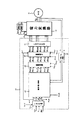
第二の実施例は、第一の実施例に対して手段41の構成のみが異なるため、図21、図25を用いてその差異のみを説明する。図21は本実施例の制御構成を示しており、実施例1の手段41に、さらにモータ損失指令値Wrefを入力する構成となっている。このブロックを41aとする。41aは、外部より与えられるトルク指令Te*とモータ回転速度ωと電源bの電力指令値Pb*と電力変換器30のキャリア周波数値fcと、モータ20のインダクタンス値Ldとモータ損失指令値Wrefから、交流モータのd軸電流の指令値id*とq軸電流の指令値iq*、分配電力目標値rto_pa、d軸電圧補正値vd_0*、q軸電圧補正値vq_0*を演算するトルク制御手段であり、モータ損失指令値にモータ損失が追従するようにid*,iq*,rto_pa,vd_0*,vq_0*を生成する。
Second embodiment (equivalent to the seventh invention)
Since the second embodiment differs from the first embodiment only in the configuration of the means 41, only the difference will be described with reference to FIGS. FIG. 21 shows a control configuration of the present embodiment, in which a motor loss command value Wref is further input to the means 41 of the first embodiment. This block is designated 41a. 41a is based on the torque command Te *, the motor rotational speed ω, the power command value Pb * of the power source b, the carrier frequency value fc of the
トルク制御手段41aの動作を図25のフローチャートに示す。トルク指令値が0か0以外かを判別し、0である場合は演算2により指令値を生成する。演算2はモータの損失式(11)から得られる。すなわち、モータの損失式からVd_0*を逆算することによって補正電圧指令値を生成する構成となっている。また、トルク指令が0以外である場合はTe* ω Pb*を軸とする三次元マップにより指令値を生成する。
The operation of the torque control means 41a is shown in the flowchart of FIG. It is determined whether the torque command value is 0 or other than 0, and if it is 0, the command value is generated by
本実施例の構成により、モータ損失をモータ損失指令値に追従させるように電流指令値と補正電圧指令値を生成する。従って、モータ損失を最小化する補正電圧指令値が直流電圧制限で出せない場合などにも指令値を調整することで最適な補正電圧指令値を生成することができるため効率が良い。 With the configuration of this embodiment, the current command value and the correction voltage command value are generated so that the motor loss follows the motor loss command value. Therefore, even when the correction voltage command value that minimizes the motor loss cannot be obtained due to the DC voltage limit, the optimum correction voltage command value can be generated by adjusting the command value, which is efficient.
第三の実施例(dq軸で電圧の配分と補正値加算、第5の発明に相当)
第三の実施例は、第一の実施例とは電流・電力制御の構成のみが異なるため、図12を用いて、その差異について説明する。電流制御手段43aの出力であるd軸電圧指令値vd*、q軸電圧指令値vq*は、乗算器43b1と43b2で、それぞれrto_paを乗じて、電源10a側の電圧指令値であるvd_a,vq_aを演算する。
vd_a = vd* ・ rto_pa
vq_a = vq* ・ rto_pa
これら出力に、電圧補正値vd_0*,vq_0*を加算器43c1,43c2でそれぞれ加算し、最終的な電源10a側のdq軸電圧指令値であるvd_a*,vq_a*を得る。
vd_a* = vd_a + vd_0*
vq_a* = vq_a + vq_0*
一方、電源10b側のdq軸電圧指令値vd_b*,vq_b*は、43aの出力vd*,vq*から、電源10a
側のdq軸電圧指令値を減算器43d1,43d2で、それぞれ減算して求める。
vd_b* = vd* - vd_a*
vq_b* = vq* - vq_a*
dq/3相変換器43e1,43e2は、dq軸電圧(2相)を3相電圧指令に変換するdq/3相電圧変換手段であり、電源10a側vd_a*,vq_a*、電源10b側vd_b*,vq_b*を3相電圧指令に変換する。以上のように演算された3相電圧指令値に基づいて、手段45以降の操作を行って電力変換装置を制御する。本実施例の構成では、第一の実施例よりも、乗算・加算・減算の回数が少なくて済み、制御演算に用いるマイコンの演算時間を削減することができる(第5の発明の効果に相当する)。
Third embodiment (voltage distribution and correction value addition on the dq axis, equivalent to the fifth invention)
Since the third embodiment is different from the first embodiment only in the configuration of current / power control, the difference will be described with reference to FIG. The d-axis voltage command value vd * and the q-axis voltage command value vq *, which are the outputs of the current control means 43a, are multiplied by rto_pa in the multipliers 43b1 and 43b2, respectively, and vd_a, vq_a which are voltage command values on the power supply 10a side. Is calculated.
vd_a = vd * ・ rto_pa
vq_a = vq * ・ rto_pa
Voltage correction values vd_0 * and vq_0 * are added to these outputs by adders 43c1 and 43c2, respectively, to obtain final dq-axis voltage command values vd_a * and vq_a * on the power supply 10a side.
vd_a * = vd_a + vd_0 *
vq_a * = vq_a + vq_0 *
On the other hand, the dq-axis voltage command values vd_b * and vq_b * on the power supply 10b side are derived from the outputs vd * and vq * of 43a to the power supply 10a.
The dq axis voltage command value on the side is subtracted by subtractors 43d1 and 43d2, respectively.
vd_b * = vd *-vd_a *
vq_b * = vq *-vq_a *
The dq / three-phase converters 43e1 and 43e2 are dq / three-phase voltage conversion means for converting the dq axis voltage (two phases) into a three-phase voltage command. The power supply 10a side vd_a *, vq_a * and the power supply 10b side vd_b * , vq_b * is converted into a three-phase voltage command. Based on the three-phase voltage command value calculated as described above, the operation after the
第四の実施例(オフセット量計算、第8の発明に相当)
第四の実施例は、図13、図14を用いて、第三の実施例との差異のみについて説明する。図14は、電流・電力制御の詳細なブロック図を示しており、電流制御手段44a、乗算器44b1,44b2、加算器44c1,44c2、減算器44d1,44d2、dq/3相変換器44e1,44e2は実施例2と同様の処理を行い、さらに電圧振幅演算器44f1,44f2が追加されている。この演算では、vd_a*,vq_a*,vd_b*,vq_b*から、a・bそれぞれの電圧ベクトルの大きさ|V_a|,|V_b|を求める。
これら電圧ベクトルの大きさは、変調率補正手段46aで、図5に代わって以下のように
用いられる。電源電圧Vdc_a、Vdc_bと、求められた|V_a|,|V_b|を用いて、次の式に基づいて電源10a分瞬時変調率指令mu_a*、電源10b分瞬時変調率指令mu*_bの補正を行う。
このようにして、補正電圧指令値を加算する場合でも、電圧の振幅に応じた変調率補正を演算することが可能になる。実施例1では、変調率指令を出力するために、補正電圧相当の時間幅を余分に確保しているが、本実施例では、補正電圧を加算した後の電圧ベクトルの大きさから時間幅を求めていることになり、出力が可能な電圧の大きさに余裕が生じる。また、実施例1の補正演算に比べて分岐演算がなく、分岐演算に演算時間を要するようなマイコンにおいては、演算量を削減することが可能になる(フローチャートに記載した分の演算量が削減可能であり、これは第7の発明の効果に相当する)。
Fourth embodiment (offset amount calculation, equivalent to the eighth invention)
In the fourth embodiment, only differences from the third embodiment will be described with reference to FIGS. FIG. 14 shows a detailed block diagram of current / power control. Current control means 44a, multipliers 44b1, 44b2, adders 44c1, 44c2, subtractors 44d1, 44d2, dq / 3-phase converters 44e1, 44e2 The same processing as in the second embodiment is performed, and voltage amplitude calculators 44f1 and 44f2 are further added. In this calculation, the magnitudes | V_a | and | V_b | of the voltage vectors a and b are obtained from vd_a *, vq_a *, vd_b *, and vq_b *.
The magnitudes of these voltage vectors are used in the modulation rate correction means 46a as follows instead of FIG. Using the power supply voltages Vdc_a and Vdc_b and the obtained | V_a | and | V_b | Do.
In this way, even when the correction voltage command value is added, it is possible to calculate the modulation rate correction according to the voltage amplitude. In the first embodiment, in order to output the modulation rate command, an extra time width corresponding to the correction voltage is secured. However, in this embodiment, the time width is calculated from the magnitude of the voltage vector after the correction voltage is added. As a result, there is a margin in the magnitude of the voltage that can be output. Further, in a microcomputer that does not have a branch operation compared to the correction operation of the first embodiment and requires a calculation time for the branch operation, the amount of calculation can be reduced (the amount of calculation described in the flowchart is reduced). This is possible and corresponds to the effect of the seventh invention).
本発明を諸図面や実施例に基づき説明してきたが、当業者であれば本開示に基づき種々の変形や修正を行うことが容易であることに注意されたい。従って、これらの変形や修正は本発明の範囲に含まれることに留意されたい。 Although the present invention has been described based on the drawings and examples, it should be noted that those skilled in the art can easily make various modifications and corrections based on the present disclosure. Therefore, it should be noted that these variations and modifications are included in the scope of the present invention.
10a,10b 電源
15 共通負極母線
107a,108a,109a,101a/101b,102a/102b,103a/103b,104a/104b,105a/105b,106a/106b 半導体スイッチ
107b,108b,109b ダイオード
14 電源10aの正極母線
16 電源10bの正極母線
12,13 平滑コンデンサ
20 モータ
30 電力変換器
30U、30V、30W U相、V相、W相のスイッチ群
40 制御装置
41、41a トルク制御手段
42 電流・電力制御手段
45 変調率演算手段
46 変調率補正手段
46,46a 変調率補正手段
47 PWMパルス生成手段
48 3相/dq変換手段
42a 電流制御器
42b, 42d dq/3相変換器
42c 乗算器
42e 加算器
42f 減算器
43a 電流制御手段
43b1,43b2 乗算器
43c1,43c2 加算器
43d1,43d2 減算器
43e1,43e2 dq/3相変換器
44a 電流制御手段
44b1,44b2 乗算器
44c1,44c2 加算器
44d1,44d2 減算器
44e1,44e2 dq/3相変換器
44f1,44f2 電圧振幅演算器
10a, 10b power supply
15 Common negative electrode bus
107a, 108a, 109a, 101a / 101b, 102a / 102b, 103a / 103b, 104a / 104b, 105a / 105b, 106a / 106b Semiconductor switch
107b, 108b, 109b Diode
14 Positive bus of power supply 10a
16 Power supply 10b positive bus
12,13 Smoothing capacitor
20 Motor
30 Power converter
30U, 30V, 30W U phase, V phase, W phase switch group
40 Control unit
41, 41a Torque control means
42 Current / power control means
45 Modulation rate calculation means
46 Modulation rate correction means
46,46a Modulation rate correction means
47 PWM pulse generation means
48 Three-phase / dq conversion means
42a Current controller
42b, 42d dq / 3-phase converter
42c multiplier
42e adder
42f subtractor
43a Current control means
43b1,43b2 multiplier
43c1,43c2 adder
43d1,43d2 subtractor
43e1, 43e2 dq / 3 phase converter
44a Current control means
44b1,44b2 multiplier
44c1,44c2 adder
44d1,44d2 subtractor
44e1,44e2 dq / 3 phase converter
44f1,44f2 Voltage amplitude calculator
Claims (10)
一方の直流電源から他方の直流電源への充電量を指令する電源電力指令値と、モータトルク指令値と、モータ回転速度とから、前記交流モータの電流指令値と、充電目標値に相当する補正電圧指令値とを生成するモータ電流指令値生成手段と、
前記モータ電流指令値に基づいてモータ電圧指令値を求めるモータ電圧指令値生成手段と、
前記モータ電圧指令値手段と複数の直流電源に各々対応した電力分配目標値とから各々の直流電源がモータへ出力する電圧の指令値を生成する配分電圧指令値生成手段と、
前記補正電圧指令値に前記配分電圧指令値を加算した電圧指令値に基づいて電力変換装置の出力電圧パルスを生成するパルス生成手段と、
を備えることを特徴とする電力変換装置。 A power converter that is connected to a plurality of DC power supplies, generates a drive voltage of an AC motor by generating and synthesizing pulses from output voltages of each of these power supplies, and drives the AC motor,
Correction corresponding to the current command value of the AC motor and the charge target value from the power supply command value commanding the charge amount from one DC power supply to the other DC power supply, the motor torque command value, and the motor rotation speed Motor current command value generating means for generating a voltage command value;
Motor voltage command value generating means for obtaining a motor voltage command value based on the motor current command value;
Distributed voltage command value generating means for generating a command value of a voltage output from each DC power supply to the motor from the motor voltage command value means and a power distribution target value corresponding to each of the plurality of DC power supplies;
Pulse generating means for generating an output voltage pulse of a power converter based on a voltage command value obtained by adding the distribution voltage command value to the correction voltage command value;
A power conversion device comprising:
前記モータ電流指令値生成手段が、
前記電源電力指令値と前記モータトルク指令値と前記モータ回転速度から、予め作成されたマップを参照することにより、前記交流モータの電流指令値と前記補正電圧指令値とを生成する、
ことを特徴とする電力変換装置。 The power conversion device according to claim 1,
The motor current command value generating means is
The current command value of the AC motor and the correction voltage command value are generated by referring to a map prepared in advance from the power supply power command value, the motor torque command value, and the motor rotation speed.
The power converter characterized by the above-mentioned.
前記モータ電流指令値生成手段が、
前記モータトルク指令値または前記モータ回転速度のいずれかが0或いは0近傍である場合に、前記電源電力指令値に基づいて、前記交流モータのトルクを生じない電流成分を、前記交流モータの電流指令値として生成する、
ことを特徴とする電力変換装置。 The power conversion device according to claim 1,
The motor current command value generating means is
When either the motor torque command value or the motor rotation speed is 0 or close to 0, a current component that does not generate torque of the AC motor is determined based on the power supply command value. Generate as value,
The power converter characterized by the above-mentioned.
前記モータ電流指令値生成手が、
前記モータトルク指令値または前記モータ回転速度のいずれかが0或いは0近傍である場合に、前記モータの損失が最小化するように、前記交流モータの電流指令値と補正電圧指令値を生成することを特徴とする、
ことを特徴とする電力変換装置。 The power conversion device according to claim 3,
The motor current command value generator is
When the motor torque command value or the motor rotation speed is 0 or close to 0, the current command value and the correction voltage command value for the AC motor are generated so that the loss of the motor is minimized. Characterized by the
The power converter characterized by the above-mentioned.
前記交流モータの電流指令値と前記補正電圧指令値が、前記交流モータのインダクタンス値とキャリア周波数と電源電力指令値とに基づいて、前記交流モータの銅損が最小となるように生成することを特徴とする、
ことを特徴とする電力変換装置。 The power conversion device according to claim 4,
The AC motor current command value and the correction voltage command value are generated based on the AC motor inductance value, carrier frequency, and power supply command value so that the copper loss of the AC motor is minimized. Features
The power converter characterized by the above-mentioned.
前記交流モータの電流指令値が、
前記補正電圧指令値が、
である(ここで、Id* = d軸電流指令値、Vd_0* = 補正電圧指令値、Pb* = 電源電力指令値、Ld = モータd軸インダクタンス値、fc = キャリア周波数値である。)、
ことを特徴とする電力変換装置。 The power conversion device according to claim 5,
The current command value of the AC motor is
The correction voltage command value is
(Where Id * = d-axis current command value, Vd_0 * = corrected voltage command value, Pb * = power supply command value, Ld = motor d-axis inductance value, fc = carrier frequency value)
The power converter characterized by the above-mentioned.
モータ損失指令値を生成するモータ損失指令生成器と、
モータ損失を演算する損失演算器と、をさらに備え、
前記モータ電流指令値生成手段が、
前記モータ損失が前記モータ損失指令値と一致するよう前記交流モータの電流指令値と補正電圧指令値とを生成する、
ことを特徴とする電力変換装置。 The power conversion device according to claim 3,
A motor loss command generator for generating a motor loss command value;
A loss calculator for calculating the motor loss;
The motor current command value generating means is
Generating a current command value and a correction voltage command value for the AC motor so that the motor loss matches the motor loss command value;
The power converter characterized by the above-mentioned.
前記モータ補正電圧指令値をdq軸補正電圧指令値とし、
前記モータ電圧指令値生成手段が、前記モータ電圧指令値として、dq軸電流指令値に基づいてdq軸モータ電圧指令値を求め、
前記指令値補正手段が、前記電力配分比率指令値と前記dq軸モータ電圧指令値の積を演算してdq軸配分電圧指令値を求めるとともに、これに前記dq軸補正電圧指令値を加算する、
ことを特徴とする電力変換装置。 The power conversion device according to claim 1,
The motor correction voltage command value is a dq axis correction voltage command value,
The motor voltage command value generating means obtains a dq axis motor voltage command value as the motor voltage command value based on a dq axis current command value,
The command value correcting means calculates a product of the power distribution ratio command value and the dq axis motor voltage command value to obtain a dq axis distribution voltage command value, and adds the dq axis correction voltage command value to this.
The power converter characterized by the above-mentioned.
配分電圧指令値を電源電圧で規格化した変調率指令値を演算する変調率演算手段と、
前記複数の直流電源の電源電圧値と、電力配分比率指令値と、補正電圧指令値とから変調率補正値を演算する第1の変調率補正手段とを、さらに備え、
前記指令値補正手段が、前記変調率指令値に前記変調率補正値を加算した値に基づいて、前記電圧指令値を求める、
ことを特徴とする電力変換装置。 In the power converter device according to any one of claims 1 to 8,
A modulation factor calculation means for calculating a modulation factor command value obtained by standardizing the distribution voltage command value with the power supply voltage;
A first modulation rate correction means for calculating a modulation rate correction value from a power supply voltage value of the plurality of DC power supplies, a power distribution ratio command value, and a correction voltage command value;
The command value correction means obtains the voltage command value based on a value obtained by adding the modulation factor correction value to the modulation factor command value;
The power converter characterized by the above-mentioned.
配分電圧指令値を電源電圧で規格化した変調率指令値を演算する変調率演算手段と、
前記複数の直流電源の電源電圧値と配分電圧指令値とから変調率補正値を演算する第2の変調率補正手段とを備え、
前記指令値補正手段が、
前記変調率指令値に前記変調率補正値を加算した値に基づいて、前記電圧指令値を求める、
ことを特徴とする電力変換装置。 In the power converter device according to any one of claims 1 to 9,
A modulation factor calculation means for calculating a modulation factor command value obtained by standardizing the distribution voltage command value with the power supply voltage;
A second modulation rate correction means for calculating a modulation rate correction value from a power supply voltage value and a distributed voltage command value of the plurality of DC power supplies,
The command value correcting means is
Obtaining the voltage command value based on a value obtained by adding the modulation factor correction value to the modulation factor command value;
The power converter characterized by the above-mentioned.
Priority Applications (3)
| Application Number | Priority Date | Filing Date | Title |
|---|---|---|---|
| JP2006074652A JP4765700B2 (en) | 2005-06-01 | 2006-03-17 | Power converter |
| US11/444,161 US7557527B2 (en) | 2005-06-01 | 2006-05-31 | Electrical power converter and control method |
| EP06252828.6A EP1732202B1 (en) | 2005-06-01 | 2006-06-01 | Electrical power conversion |
Applications Claiming Priority (3)
| Application Number | Priority Date | Filing Date | Title |
|---|---|---|---|
| JP2005161513 | 2005-06-01 | ||
| JP2005161513 | 2005-06-01 | ||
| JP2006074652A JP4765700B2 (en) | 2005-06-01 | 2006-03-17 | Power converter |
Publications (2)
| Publication Number | Publication Date |
|---|---|
| JP2007014185A JP2007014185A (en) | 2007-01-18 |
| JP4765700B2 true JP4765700B2 (en) | 2011-09-07 |
Family
ID=36972989
Family Applications (1)
| Application Number | Title | Priority Date | Filing Date |
|---|---|---|---|
| JP2006074652A Active JP4765700B2 (en) | 2005-06-01 | 2006-03-17 | Power converter |
Country Status (3)
| Country | Link |
|---|---|
| US (1) | US7557527B2 (en) |
| EP (1) | EP1732202B1 (en) |
| JP (1) | JP4765700B2 (en) |
Cited By (1)
| Publication number | Priority date | Publication date | Assignee | Title |
|---|---|---|---|---|
| JP2019030095A (en) * | 2017-07-28 | 2019-02-21 | 澤藤電機株式会社 | Motor controller and motor control method |
Families Citing this family (12)
| Publication number | Priority date | Publication date | Assignee | Title |
|---|---|---|---|---|
| EP1833151B1 (en) | 2006-03-07 | 2017-06-14 | Nissan Motor Co., Ltd. | Power conversion apparatus |
| JP4760465B2 (en) | 2006-03-17 | 2011-08-31 | 日産自動車株式会社 | Power converter |
| KR101091745B1 (en) * | 2010-04-22 | 2011-12-08 | 엘지전자 주식회사 | Motor controlling apparatus and controlling method of the same |
| DE102012200804A1 (en) * | 2012-01-20 | 2013-07-25 | Continental Automotive Gmbh | On-board network and method for operating a vehicle electrical system |
| JP2015046989A (en) * | 2013-08-28 | 2015-03-12 | 日本電産テクノモータ株式会社 | Motor driving apparatus |
| EP2908416B1 (en) * | 2013-12-24 | 2020-12-02 | LG Electronics Inc. | Motor driving device and air conditioner including the same |
| KR101535036B1 (en) * | 2014-08-25 | 2015-07-24 | 현대자동차주식회사 | Apparatus and Method for compensating torque about current order of driving motor |
| KR102366401B1 (en) * | 2014-10-13 | 2022-02-22 | 엘지전자 주식회사 | Motor driving device and air conditioner including the same |
| US11063532B2 (en) * | 2017-05-18 | 2021-07-13 | Toshiba Mitsubishi-Electric Industrial Systems Corporation | Power conversion device superimposing a tertiary harmonic wave |
| JP7151111B2 (en) * | 2018-03-22 | 2022-10-12 | 株式会社デンソー | electric motor drive |
| JP7114968B2 (en) * | 2018-03-22 | 2022-08-09 | 株式会社デンソー | electric motor drive |
| DE102020203010A1 (en) * | 2020-07-16 | 2022-01-20 | Robert Bosch Gesellschaft mit beschränkter Haftung | Method for operating a pump motor of an actuating device, actuating device, motor vehicle |
Family Cites Families (20)
| Publication number | Priority date | Publication date | Assignee | Title |
|---|---|---|---|---|
| JPS62247703A (en) * | 1986-04-21 | 1987-10-28 | Toyota Motor Corp | Control of induction motor for electric automobile |
| JPH08331882A (en) * | 1995-03-24 | 1996-12-13 | Seiko Epson Corp | Motor controller |
| JPH08336205A (en) * | 1995-04-07 | 1996-12-17 | Nippon Soken Inc | Battery charger for hybrid vehicle |
| JP3487952B2 (en) * | 1995-04-14 | 2004-01-19 | 株式会社日立製作所 | Drive device and drive control method for electric vehicle |
| WO1998035903A1 (en) * | 1997-02-14 | 1998-08-20 | Hitachi, Ltd. | Control device for induction motor and control device for elevator |
| US6342984B1 (en) * | 1998-07-01 | 2002-01-29 | Western Digital Technologies, Inc | Disk drive including DC to DC voltage converter for increasing voltage to its spindle motor and VCM |
| DE19846319C1 (en) * | 1998-10-08 | 2000-02-17 | Daimler Chrysler Ag | Energy supply circuit for automobile electrical network, uses multi-level controller with input/output terminals coupled to respective voltage supply paths for HV and LV loads and back-up storage battery |
| JP4134439B2 (en) * | 1999-04-30 | 2008-08-20 | トヨタ自動車株式会社 | Power conversion system |
| US6268711B1 (en) * | 1999-05-05 | 2001-07-31 | Texas Instruments Incorporated | Battery manager |
| JP4218202B2 (en) * | 2000-10-04 | 2009-02-04 | トヨタ自動車株式会社 | DC power supply with fuel cell |
| JP4206630B2 (en) * | 2000-10-04 | 2009-01-14 | トヨタ自動車株式会社 | DC power supply with fuel cell |
| JP3502040B2 (en) | 2000-12-27 | 2004-03-02 | 本田技研工業株式会社 | Brushless DC motor constant detection device, brushless DC motor control device, and brushless DC motor constant detection program |
| JP3625789B2 (en) * | 2001-08-10 | 2005-03-02 | 本田技研工業株式会社 | Vehicle power supply |
| KR100460881B1 (en) * | 2002-06-28 | 2004-12-09 | 현대자동차주식회사 | System and method for controlling power conversion of fuel cell hybrid electric vehicle |
| JP2004040861A (en) * | 2002-07-01 | 2004-02-05 | Sanyo Electric Co Ltd | Driving-gear of motor |
| US7193392B2 (en) * | 2002-11-25 | 2007-03-20 | Tiax Llc | System and method for determining and balancing state of charge among series connected electrical energy storage units |
| US7050311B2 (en) * | 2003-11-25 | 2006-05-23 | Electric Power Research Institute, Inc. | Multilevel converter based intelligent universal transformer |
| US7057371B2 (en) * | 2004-04-19 | 2006-06-06 | General Motors Corporation | Inverter for electric and hybrid powered vehicles and associated system and method |
| EP1615325B1 (en) * | 2004-07-07 | 2015-04-22 | Nissan Motor Co., Ltd. | Power conversion and vehicle |
| EP1653602B1 (en) * | 2004-10-29 | 2019-07-03 | Nissan Motor Co., Ltd. | Motor drive system and process |
-
2006
- 2006-03-17 JP JP2006074652A patent/JP4765700B2/en active Active
- 2006-05-31 US US11/444,161 patent/US7557527B2/en active Active
- 2006-06-01 EP EP06252828.6A patent/EP1732202B1/en active Active
Cited By (2)
| Publication number | Priority date | Publication date | Assignee | Title |
|---|---|---|---|---|
| JP2019030095A (en) * | 2017-07-28 | 2019-02-21 | 澤藤電機株式会社 | Motor controller and motor control method |
| JP7042568B2 (en) | 2017-07-28 | 2022-03-28 | 澤藤電機株式会社 | Motor control device and motor control method |
Also Published As
| Publication number | Publication date |
|---|---|
| EP1732202A3 (en) | 2008-03-12 |
| EP1732202A2 (en) | 2006-12-13 |
| JP2007014185A (en) | 2007-01-18 |
| US20060273748A1 (en) | 2006-12-07 |
| EP1732202B1 (en) | 2015-08-12 |
| US7557527B2 (en) | 2009-07-07 |
Similar Documents
| Publication | Publication Date | Title |
|---|---|---|
| JP4765700B2 (en) | Power converter | |
| JP4760465B2 (en) | Power converter | |
| JP5549384B2 (en) | Electric motor control device and electric motor control system | |
| JP5157356B2 (en) | Power converter and control method thereof | |
| EP2372894B1 (en) | Direct-current to three-phase alternating-current inverter system | |
| JP4775168B2 (en) | Control device for three-phase rotating machine | |
| CN110311617B (en) | Motor driving system and method | |
| CN113491063A (en) | Motor driving device | |
| JP2004304868A (en) | Motor controller | |
| JP6119585B2 (en) | Electric motor drive | |
| JP2009201250A (en) | Controller of electric motor | |
| JP5017911B2 (en) | Power converter | |
| JP4992253B2 (en) | Power converter | |
| JP5320850B2 (en) | Power conversion device and automobile system | |
| JP4844051B2 (en) | Power converter | |
| JP4797371B2 (en) | Power converter control method | |
| JP2021168566A (en) | Motor drive system | |
| JP2006121855A (en) | Ac motor control device | |
| JP5338853B2 (en) | Power converter | |
| JP7251336B2 (en) | motor controller | |
| WO2023162860A1 (en) | Ac motor control device and program | |
| JP2007236063A (en) | Device for controlling power converter | |
| JP4691974B2 (en) | Power converter control method | |
| JP4899536B2 (en) | Power converter | |
| JP2004274806A (en) | Motor controller |
Legal Events
| Date | Code | Title | Description |
|---|---|---|---|
| A621 | Written request for application examination |
Free format text: JAPANESE INTERMEDIATE CODE: A621 Effective date: 20090204 |
|
| A977 | Report on retrieval |
Free format text: JAPANESE INTERMEDIATE CODE: A971007 Effective date: 20110427 |
|
| TRDD | Decision of grant or rejection written | ||
| A01 | Written decision to grant a patent or to grant a registration (utility model) |
Free format text: JAPANESE INTERMEDIATE CODE: A01 Effective date: 20110517 |
|
| A61 | First payment of annual fees (during grant procedure) |
Free format text: JAPANESE INTERMEDIATE CODE: A61 Effective date: 20110530 |
|
| R150 | Certificate of patent or registration of utility model |
Free format text: JAPANESE INTERMEDIATE CODE: R150 Ref document number: 4765700 Country of ref document: JP Free format text: JAPANESE INTERMEDIATE CODE: R150 |
|
| FPAY | Renewal fee payment (event date is renewal date of database) |
Free format text: PAYMENT UNTIL: 20140624 Year of fee payment: 3 |