JP4760163B2 - Game machine - Google Patents
Game machine Download PDFInfo
- Publication number
- JP4760163B2 JP4760163B2 JP2005191075A JP2005191075A JP4760163B2 JP 4760163 B2 JP4760163 B2 JP 4760163B2 JP 2005191075 A JP2005191075 A JP 2005191075A JP 2005191075 A JP2005191075 A JP 2005191075A JP 4760163 B2 JP4760163 B2 JP 4760163B2
- Authority
- JP
- Japan
- Prior art keywords
- display
- information
- effect
- symbol
- display information
- Prior art date
- Legal status (The legal status is an assumption and is not a legal conclusion. Google has not performed a legal analysis and makes no representation as to the accuracy of the status listed.)
- Active
Links
Images


Description
本発明は、パチンコ機等に代表される遊技機に関するものである。 The present invention relates to a gaming machine represented by a pachinko machine or the like.
従来、例えば、遊技の制御を行う主制御装置と、その主制御装置で行われる遊技の制御に伴った表示を、液晶画面を有する表示装置で行わせる表示制御装置とを備えたパチンコ機が知られている。このパチンコ機の液晶画面では、変動演出や大当たり演出が行われる。変動演出は、入球口に球が入球することで開始される演出であり、図柄が変動する演出である。大当たり演出は、変動演出で所定の図柄が停止表示した後に行われる演出であり、遊技者に大量の賞球が払い出される大当たりが発生した場合に行われる演出である。 Conventionally, for example, a pachinko machine having a main control device that controls a game and a display control device that displays a display associated with the game control performed by the main control device on a display device having a liquid crystal screen is known. It has been. On the liquid crystal screen of this pachinko machine, variation effects and jackpot effects are performed. The fluctuating effect is an effect that starts when a ball enters the entrance, and is an effect in which the pattern fluctuates. The jackpot effect is an effect that is performed after a predetermined symbol is stopped and displayed as a variable effect, and is an effect that is performed when a jackpot in which a large amount of prize balls are paid out to the player occurs.
変動演出や大当たり演出を行うためのキャラクタ情報(所謂、画像データ)は、ROMに予め記憶されている。パチンコ機の電源が投入されると、キャラクタ情報は、ROMから読み出されてRAMへ書き込まれる。そして、各種演出は、RAMに記憶されたキャラクタ情報から、各演出に必要な情報が適宜読み出されて行われる(特許文献1参照)。 Character information (so-called image data) for performing a variation effect or a jackpot effect is stored in advance in the ROM. When the pachinko machine is powered on, the character information is read from the ROM and written to the RAM. Various effects are performed by appropriately reading out information necessary for each effect from the character information stored in the RAM (see Patent Document 1).
なお、電源投入時にキャラクタ情報をROMから読み出してRAMに書き込むのは、各種演出の処理を高速に行い、スムーズな表示を行うためである。これは、ROMよりRAMの方が処理速度が高速に行えると共に、キャラクタ情報をROMから読み出して加工(例えば、図柄の大きさの変更や背景の色の変更)する場合と比較して、RAMにおいてキャラクタ情報を容易に加工できるからである。
上述した通り、上記パチンコ機は、電源が投入されると、キャラクタ情報をROMから読み出してRAMへ書き込むので、キャラクタ情報のデータ量が膨大であると、その書き込み処理に時間がかかる。表示制御装置は、ROMからRAMへのキャラクタ情報の書き込みが完了するまでは、入球口に球が入球したとしても変動演出を行えない。よって、遊技者が、パチンコ機の電源投入直後に遊技を開始した場合には、入球口に球が入球しても、表示装置で変動演出を行うことができないという問題点があった。 As described above, when the pachinko machine is turned on, the character information is read from the ROM and written to the RAM. Therefore, if the data amount of the character information is enormous, the writing process takes time. Until the writing of the character information from the ROM to the RAM is completed, the display control device cannot perform a fluctuating effect even if a ball enters the entrance. Therefore, when the player starts the game immediately after turning on the power of the pachinko machine, there is a problem that even if the ball enters the entrance, the display device cannot perform the changing effect.
また、近年では、パチンコ機の遊技性の向上のために、表示装置の液晶画面が大規模化されたり、その液晶画面で表示される画像が細密化されているので、キャラクタ情報のデータ量は増大傾向にある。そのため、キャラクタ情報を圧縮形式でROMに記憶してデータ量を少なくすることが行われている。ROMに圧縮形式でキャラクタ情報が記憶されていると、そのキャラクタ情報をRAMへ書き込む場合には、圧縮形式のデータの解凍処理が追加されるので、キャラクタ情報のRAMへの書き込み完了までには更に時間を有してしまうという問題点があった。 In recent years, the liquid crystal screen of the display device has been enlarged or the images displayed on the liquid crystal screen have been miniaturized in order to improve the playability of pachinko machines. It is increasing. Therefore, character information is stored in ROM in a compressed format to reduce the data amount. When character information is stored in the ROM in a compressed format, when the character information is written to the RAM, a decompression process of the data in the compressed format is added. There was a problem of having time.
本発明は、上述した問題点を解決するためになされたものであり、電源投入後に表示装置での表示を早期に開始できる遊技機を提供することを目的としている。 The present invention has been made to solve the above-described problems, and an object thereof is to provide a gaming machine that can start display on a display device at an early stage after power-on.
この目的を達成するために請求項1記載の遊技機は、遊技の制御を行う主制御手段と、その主制御手段により制御される遊技に伴った表示が行われる表示装置と、その表示装置で行われる表示の制御を行う表示制御手段と、その表示制御手段と主制御手段とに駆動電圧を供給する電源手段とを備えるものであり、前記表示制御手段は、前記表示装置で表示を行うための第1の表示情報があらかじめ記憶されると共に、その記憶された表示情報が読み出し可能に構成された第1記憶手段と、前記第1の表示情報の少なくとも一部に対応した第2の表示情報が、その対応する表示情報に対して少ない情報量であらかじめ記憶されると共に、その記憶された第2の表示情報が読み出し可能に構成された第2記憶手段と、前記電源手段により駆動電圧が供給されると、前記第1及び第2の表示情報を前記第1及び第2記憶手段からそれぞれ読み出す読出手段と、その読出手段により読み出された第1及び第2の表示情報が記憶されると共に、書き込み及び読み出し可能に構成された第3記憶手段と、前記読出手段により読み出される第1の表示情報が前記第3記憶手段に記憶されるまでの間は前記表示装置の表示を前記第2の表示情報に基づいて行うと共に、前記第1の表示情報が前記第3記憶手段に記憶された後に前記表示装置の表示をその第1の表示情報に基づいて行う演出実行手段とを備えている。
In order to achieve this object, a gaming machine according to
この遊技機の電源が投入されると、電源手段により駆動電圧が供給されて読出手段により第1及び第2の表示情報が読み出される。その読み出された第1及び第2の表示情報は第3記憶手段に記憶されるが、第2の表示情報が第1の表示情報に比べて情報量が少ないので、第2の表示情報の第3記憶手段への記憶が早期に完了される。そして、第1の表示情報が第3記憶手段に記憶されるまでは、演出実行手段により第2の表示情報に基づいた表示が表示装置で行われる。
請求項2記載の遊技機は、請求項1記載の遊技機において、前記演出実行手段は、前記第1又は第2の表示情報に基づいて複数の変動演出の表示を実行可能に構成され、前記第2の表示情報に基づく変動演出の表示が実行されていない場合に、前記第2の表示情報に基づく変動演出から第1の表示情報に基づく変動演出への切り替えを行う切替手段を備えている。
請求項3記載の遊技機は、請求項2記載の遊技機において、始動条件が成立することに伴い抽選を行う抽選手段と、前記始動条件が成立した場合に表示情報の変動演出を開始する変動演出開始手段と、前記抽選手段による抽選結果に応じた表示情報を停止表示させる停止表示手段とを備え、前記演出実行手段により実行される1の変動演出は、1の始動条件の成立に伴い前記変動演出開始手段により表示情報の変動演出が開始されてから、前記停止表示手段により表示情報が停止表示されるまでの期間であり、前記切替手段は、前記1の変動演出が開始される前に、前記第2の表示情報に基づく変動演出から第1の表示情報に基づく変動演出への切り替えを行うものである。
請求項4記載の遊技機は、請求項2又は3に記載の遊技機において、前記第1記憶手段から第1の表示情報を読み出して前記第3記憶手段へ書き込む書込処理は、前記表示制御手段において所定間隔毎に繰り返し実行される割込処理で行われる一方、前記演出実行手段により前記第2の表示情報に基づいて実行される変動演出の表示処理は、前記表示制御手段の起動時から所定間隔毎に繰り返し実行されるメイン処理で行われるものである。
When the gaming machine is turned on, a driving voltage is supplied by the power supply means, and the first and second display information are read by the reading means. The read first and second display information are stored in the third storage means. However, since the second display information has a smaller amount of information than the first display information, the second display information Storage in the third storage means is completed early. Then, until the first display information is stored in the third storage means, display based on the second display information is performed on the display device by the effect execution means.
According to a second aspect of the present invention, in the gaming machine according to the first aspect, the effect executing means is configured to be capable of executing display of a plurality of variable effects based on the first or second display information, Switching means for switching from a variation effect based on the second display information to a variation effect based on the first display information when display of the variation effect based on the second display information is not executed. .
The gaming machine according to claim 3 is the gaming machine according to
The gaming machine according to
請求項1記載の遊技機によれば、第2の表示情報が第1の表示情報に比べて早期に読み出しが完了され、演出実行手段により第1の表示情報が読み出されるまでは第2の表示情報に基づく表示が表示装置で行われるので、表示装置における表示の開始を電源投入後、早期に行うことができる。よって、遊技機の電源投入直後に遊技者が遊技を開始した場合にも、表示装置での表示を早期に開始できる。
請求項2記載の遊技機によれば、請求項1記載の遊技機の奏する効果に加え、演出実行手段が、第1又は第2の表示情報に基づいて複数の変動演出の表示を実行可能に構成されており、第2の表示情報に基づく変動演出の表示が実行されていない場合に、第2の表示情報に基づく変動演出から第1の表示情報に基づく変動演出への切り替えが切替手段により行われる。
ここで、例えば、遊技中の遊技者は、大当たりへの期待ができるか否かを確認するために表示装置の変動演出に集中する。そこで、遊技中に表示装置の変動演出が突然切り替わると、遊技者はその遊技機が故障したと思い遊技を中断する。しかし、遊技者が遊技を中断すると、遊技機の稼働率を低下させてしまうし、遊技機の故障は、遊技者に不快感を与えてしまう。
しかし、請求項2記載の遊技機によれば、第2の表示情報に基づく変動演出の表示が実行されていない場合に、第2の表示情報に基づく変動演出から第1の表示情報に基づく変動演出に切り替えられるので、変動演出の途中に突然表示が切り替わることを防止できる。よって、遊技機の稼働率の低下を抑制できると共に、遊技者に不快感を与えることを低減できる。
請求項3記載の遊技機によれば、請求項2記載の遊技機の奏する効果に加え、1の変動演出が開始される前に、第2の表示情報に基づく変動演出から第1の表示情報に基づく変動演出に切り替えるので、1の変動演出が終了し且つ次の1の変動演出が開始されるまでの間に、切替手段による表示情報の切り替えを行うことができる。よって、変動演出の途中に突然表示が切り替わることを防止できる。なお、遊技機への電源の投入後に最初に開始される1の変動演出の前に、第1の表示情報が読み出されて第3記憶手段に記憶されていれば、最初の1の変動演出が開始される前に切替手段による表示情報の切り替えを行うこともできる。
また、例えば、1の始動条件の成立時に抽選手段による抽選結果が当たりであった場合には、表示情報の停止表示に連続して特別遊技状態に移行する遊技機もある。この遊技機の場合、当たりの表示情報が停止表示してから特別遊技状態に移行するまでの間、又は、特別遊技状態の終了後から次の1の変動演出が開始されるまでの間に、第2の表示情報に基づく変動演出から第1の表示情報に基づく変動演出に切り替えることができる。
請求項4記載の遊技機によれば、請求項2又は3に記載の遊技機の奏する効果に加え、表示処理をメイン処理で行いつつ、書き込み処理が割込処理で行われるので、第2の表示情報による変動演出を行いつつ第1の表示情報を効率よく読み出して書き込むことができる。
According to the gaming machine of the first aspect, the second display information is read out earlier than the first display information, and the second display information is read until the first display information is read by the effect executing means. Since the display based on the information is performed on the display device, the display on the display device can be started early after the power is turned on. Therefore, even when the player starts playing immediately after powering on the gaming machine, display on the display device can be started early .
According to the gaming machine according to
Here, for example, a player who is playing a game concentrates on the variation effect of the display device in order to confirm whether or not the big hit can be expected. Therefore, if the variation effect of the display device is suddenly switched during the game, the player thinks that the gaming machine has failed and interrupts the game. However, when the player interrupts the game, the operating rate of the gaming machine is lowered, and the failure of the gaming machine gives a discomfort to the player.
However, according to the gaming machine of the second aspect, when the display of the change effect based on the second display information is not executed, the change based on the first display information is changed from the change effect based on the second display information. Since it is switched to the production, it is possible to prevent the display from being suddenly changed during the variation production. Therefore, it is possible to suppress a decrease in the operating rate of the gaming machine and to reduce discomfort to the player.
According to the gaming machine according to claim 3, in addition to the effect of the gaming machine according to
Further, for example, there is a gaming machine that shifts to a special gaming state continuously after the display information is stopped when the lottery result by the lottery means is a win when one start condition is satisfied. In the case of this gaming machine, after the winning display information is stopped and displayed until the transition to the special gaming state, or after the end of the special gaming state until the next one variation effect is started, The change effect based on the second display information can be switched to the change effect based on the first display information.
According to the gaming machine of the fourth aspect, in addition to the effect produced by the gaming machine of the second or third aspect, the writing process is performed by the interrupt process while the display process is performed by the main process. It is possible to efficiently read and write the first display information while performing the variation effect by the display information.
以下、パチンコ遊技機(以下、単に「パチンコ機」という)の一実施形態を、図面に基づいて説明する。図1はパチンコ機10の正面図であり、図2はパチンコ機10の遊技盤13の正面図であり、図3はパチンコ機10の背面図である。
Hereinafter, an embodiment of a pachinko gaming machine (hereinafter simply referred to as “pachinko machine”) will be described with reference to the drawings. 1 is a front view of the
パチンコ機10は、図1に示すように、略矩形状に組み合わせた木枠により外殻が形成される外枠11と、その外枠11と略同一の外形形状に形成され外枠11に対して開閉可能に支持された内枠12とを備えている。外枠11には、内枠12を支持するために正面視(図1参照)左側の上下2カ所に金属製のヒンジ18が取り付けられ、そのヒンジ18が設けられた側を開閉の軸として内枠12が正面手前側へ開閉可能に支持されている。
As shown in FIG. 1, the
内枠12には、多数の釘や入賞口63,64等を有する遊技盤13(図2参照)が裏面側から着脱可能に装着される。この遊技盤13の前面を球が流下することにより弾球遊技が行われる。なお、内枠12には、球を遊技盤13の前面領域に発射する球発射ユニット112a(図4参照)やその球発射ユニット112aから発射された球を遊技盤13の前面領域まで誘導する発射レール(図示せず)等が取り付けらている。
A game board 13 (see FIG. 2) having a large number of nails, winning
内枠12の前面側には、その前面上側を覆う前面枠14と、その下側を覆う下皿ユニット15とが設けられている。前面枠14及び下皿ユニット15を支持するために正面視(図1参照)左側の上下2カ所に金属製のヒンジ19が取り付けられ、そのヒンジ19が設けられた側を開閉の軸として前面枠14及び下皿ユニット15が正面手前側へ開閉可能に支持されている。なお、内枠12の施錠と前面枠14の施錠とは、シリンダ錠20の鍵穴21に専用の鍵を差し込んで所定の操作を行うことでそれぞれ解除される。
On the front side of the
前面枠14は、装飾用の樹脂部品や電気部品等を組み付けたものであり、その略中央部には略楕円形状に開口形成された窓部14cが設けられている。前面枠14の裏面側には2枚の板ガラスを有するガラスユニット16が配設され、そのガラスユニット16を介して遊技盤13の前面がパチンコ機10の正面側に視認可能となっている。前面枠14には、球を貯留する上皿17が前方へ張り出して上面を開放した略箱状に形成されており、この上皿17に賞球や貸出球などが排出される。上皿17の底面は正面視(図1参照)右側に下降傾斜して形成され、その傾斜により上皿17に投入された球が球発射ユニット112aへと案内される。また、上皿17の上面には、枠ボタン22が設けられている。この枠ボタン22は、例えば、第3図柄表示装置81で表示される変動表示の演出パターンを変更したり、リーチ演出時の演出内容を変更したりする場合などに、遊技者により操作される。
The
加えて、前面枠14には、その周囲(例えばコーナー部分)に各種ランプ等の発光手段が設けられている。これら発光手段は、大当たり時や所定のリーチ時等における遊技状態の変化に応じて、点灯又は点滅することにより発光態様が変更制御され、遊技中の演出効果を高める役割を果たす。窓部14cの周縁には、LED等の発光手段を内蔵した電飾部29〜33が設けられている。パチンコ機10においては、これら電飾部29〜33が大当たりランプ等の演出ランプとして機能し、大当たり時やリーチ演出時等には内蔵するLEDの点灯や点滅によって各電飾部29〜33が点灯または点滅して、大当たり中である旨、或いは大当たり一歩手前のリーチ中である旨が報知される。
In addition, the
また、前面枠14の正面視(図1参照)左上部には、LED等の発光手段が内蔵され賞球の払い出し中とエラー発生時とを表示可能な表示ランプ34が設けられている。また、右側の電飾部32下側には、前面枠14の裏面側を視認できるように裏面側より透明樹脂を取り付けて小窓35が形成され、遊技盤13前面の貼着スペースK1(図2参照)に貼付される証紙等はパチンコ機10の前面から視認可能とされている。また、パチンコ機10においては、より煌びやかさを醸し出すために、電飾部29〜33の周りの領域にクロムメッキを施したABS樹脂製のメッキ部材36が取り付けられている。
Further, in the upper left part of the
窓部14cの下方には、貸球操作部40が配設されている。貸球操作部40には、度数表示部41と、球貸しボタン42と、返却ボタン43とが設けられている。パチンコ機10の側方に配置されるカードユニット(球貸しユニット)(図示せず)に紙幣やカード等を投入した状態で貸球操作部40が操作されると、その操作に応じて球の貸出が行われる。具体的には、度数表示部41はカード等の残額情報が表示される領域であり、内蔵されたLEDが点灯して残額情報として残額が数字で表示される。球貸しボタン42は、カード等(記録媒体)に記録された情報に基づいて貸出球を得るために操作されるものであり、カード等に残額が存在する限りにおいて貸出球が上皿17に供給される。返却ボタン43は、カードユニットに挿入されたカード等の返却を求める際に操作される。なお、カードユニットを介さずに球貸し装置等から上皿17に球が直接貸し出されるパチンコ機、いわゆる現金機では貸球操作部40が不要となるが、この場合には、貸球操作部40の設置部分に飾りシール等を付加して部品構成は共通のものとしても良い。カードユニットを用いたパチンコ機と現金機との共通化を図ることができる。
A ball
上皿17の下側に位置する下皿ユニット15には、その中央部に上皿17に貯留しきれなかった球を貯留するための下皿50が上面を開放した略箱状に形成されている。下皿50の右側には、球を遊技盤13の前面へ打ち込むために遊技者によって操作される操作ハンドル51が配設され、かかる操作ハンドル51の内部には球発射ユニット112aの駆動を許可するためのタッチセンサ(図示せず)と、操作ハンドル51の回動操作量を電気抵抗の変化により検出する可変抵抗器(図示せず)とが内蔵されている。操作ハンドル51が遊技者によって右回りに回転操作されると、タッチセンサがオンされると共に可変抵抗器の抵抗値が操作量に対応して変化し、操作ハンドル51の回動操作量に応じて変化する可変抵抗器の抵抗値に対応した強さで球が発射され、これにより遊技者の操作に対応した飛び量で遊技盤13の前面へ球が打ち込まれる。
In the
下皿50の正面下方部には、下皿50に貯留された球を下方へ排出する際に操作するための球抜きレバー52が設けられている。この球抜きレバー52は、常時、右方向に付勢されており、その付勢に抗して左方向へスライドさせることにより、下皿50の底面に形成された底面口が開口して、その底面口から球が自然落下して排出される。かかる球抜きレバー52の操作は、通常、下皿50の下方に下皿50から排出された球を受け取る箱(一般に「千両箱」と称される)を置いた状態で行われる。下皿50の右方には、前述したように操作ハンドル51が配設され、下皿50の左方には灰皿53が取り付けられている。
In the lower part of the front of the
遊技盤13は、図2に示すように、正面視略正方形状に切削加工した木製のベース板60に、球案内用の多数の釘や風車およびレール61,62、一般入賞口63、第1入球口64、可変入賞装置65、可変表示装置ユニット80等を組み付けて構成され、その周縁部が内枠12の裏面側に取り付けられる。一般入賞口63、第1入球口64、可変入賞装置65、可変表示装置ユニット80は、ルータ加工によってベース板60に形成された貫通穴に配設され、遊技盤13の前面側から木ネジ等により固定されている。また、遊技盤13の前面中央部分は、前面枠14の窓部14cを通じて内枠13の前面側から視認することができる。以下に、遊技盤13の構成について説明する。
As shown in FIG. 2, the
遊技盤13の前面には、帯状の金属板を略円弧状に屈曲加工して形成した外レール62が植立され、その外レール62の内側位置には外レール62と同様に帯状の金属板で形成した円弧状の内レール61が植立される。この内レール61と外レール62とにより遊技盤13の前面外周が囲まれ、遊技盤13とガラスユニット16とにより前後が囲まれることにより、遊技盤13の前面には、球の挙動により遊技が行われる遊技領域が形成される。遊技領域は、遊技盤13の前面であって2本のレール61,62と円弧部材70とにより区画して形成される略円形状の領域である。
An
2本のレール61,62は、球発射ユニット112aから発射された球を遊技盤13上部へ案内するために設けられたものである。内レール61の先端部分(図2の左上部)には戻り球防止部材68が取り付けられ、一旦、遊技盤13の上部へ案内された球が再度球案内通路内に戻ってしまうといった事態が防止される。外レール62の先端部(図2の右上部)には、球の最大飛翔部分に対応する位置に返しゴム69が取り付けられ、所定以上の勢いで発射された球は、返しゴム69に当たって、勢いが減衰されつつ中央部側へ跳ね返される。また、内レール61の右下側の先端部と外レール62の右上側の先端部との間には、レール間を繋ぐ円弧を内面側に設けて形成された樹脂製の円弧部材70がベース板60に打ち込んで固定されている。
The two
遊技領域の正面視右側上部(図2の右側上部)には、発光手段である複数のLED37aと7セグメント表示器37bとが設けられた第1図柄表示装置37が配設されている。第1図柄表示装置37は、主制御装置110で行われる各制御に応じた表示がなされるものであり、主にパチンコ機10の遊技状態の表示が行われる。複数のLED37aは、パチンコ機10が確変中か時短中か通常中であるかを点灯状態により示したり、変動中であるか否かを点灯状態により示したり、停止図柄が確変大当たりに対応した図柄か普通大当たりに対応した図柄か外れ図柄であるかを点灯状態により示したり、保留球数を点灯状態により示すものである。7セグメント表示装置37bは、大当たり中のラウンド数やエラー表示を行うものである。なお、LED37aは、それぞれのLEDの発光色(例えば、赤、緑、青)が異なるよう構成され、その発光色の組合わせにより、少ないLEDでパチンコ機10の各種遊技状態を示唆することができる。なお、上述したパチンコ機10が確変中とは、大当たり確率がアップして特別遊技状態へ移行し易い状態である。本実施の形態の確変中は、さらに、第2図柄の当たり確率がアップして第1入球口64(図3参照)へ球が入球し易い遊技の状態である。また、パチンコ機10が時短中とは、大当たり確率がそのままで第2図柄の当たり確率のみがアップして第1入球口64(図3参照)へ球が入球し易い状態の遊技中であり、パチンコ機10が通常中とは、確変中および時短中でない遊技中(大当たり確率も第2図柄の当たり確率もアップしていない状態)である。また、パチンコ機10の遊技状態に応じて、第1入球口64に付随する電動役物(図示せず)が開放する時間や、1回の当たりで開放する回数を変更するものとしても良い。
A first
また、遊技領域には、球が入賞することにより5個から15個の球が賞球として払い出される複数の一般入賞口63が配設されている。また、遊技領域の中央部分には、可変表示装置ユニット80が配設されている。可変表示装置ユニット80には、第1入球口64への入賞をトリガとして第3図柄を変動表示する液晶ディスプレイ(以下単に「LCD」と略す。)で構成された第3図柄表示装置81と、第2入球口67の球の通過をトリガとして第2図柄を変動表示する発光ダイオード(以下、「LED」と略す。)で構成される第2図柄表示装置82とが設けられている。
The game area is provided with a plurality of general winning
第3図柄表示装置81は、後述する表示制御装置114によって表示内容が制御され、、例えば左、中及び右の3つの図柄列が表示される。各図柄列は複数の図柄によって構成され、これらの図柄が図柄列毎に縦スクロールして第3図柄表示装置81の表示画面上にて第3図柄が可変表示されるようになっている。また、本実施の形態では、第3図柄表示装置81は8インチサイズの大型の液晶ディスプレイで構成され、可変表示装置ユニット80には、この第3図柄表示装置81の外周を囲むようにして、センターフレーム86が配設されている。なお、LCDに代えて、例えば、リール等を用いて第3図柄表示装置81を構成するようにしても良い。なお、本実施の形態の第3図柄表示装置81は、主制御装置110の制御に伴った遊技状態の表示が第1図柄表示装置37で行われるのに対して、その第1図柄表示装置37の表示に応じた装飾的な表示を行うものである。
The display content of the third
また、第1図柄表示装置37にて停止図柄(確変大当たり図柄、普通大当たり図柄、外れ図柄のいずれか1つ)が表示されるまでの間に球が第1入球口64へ入球した場合、その入球回数は最大4回まで保留され、その保留回数は第1図柄表示装置37により示されると共に保留ランプ85の点灯個数においても示される。保留ランプ85は、最大保留数分の4つ設けられ、第3図柄表示装置81の上方に左右対称に配設されている。なお、本実施の形態においては、第1入球口64への入賞は、最大4回まで保留されるように構成したが、最大保留回数は4回に限定されるものでなく、3回以下、又は、5回以上の回数(例えば、8回)に設定しても良い。また、保留ランプ85を削除し、第1入球口64への入賞に基づく変動表示の保留回数を第3図柄表示装置81の一部に数字で、或いは、4つに区画された領域を保留回数分だけ異なる態様(例えば、色や点灯パターン)にして表示するようにしても良い。また、第1図柄表示装置37により保留回数が示されるので、保留ランプ85により点灯表示を行わないものとしても良い。
In addition, when the ball enters the
第2図柄表示装置82は、第2図柄の表示部83と保留ランプ84とを有し、球が第2入球口67を通過する毎に、表示部83において表示図柄(第2図柄)としての「○」の図柄と「×」の図柄とが交互に点灯して変動表示が行われ、その変動表示が所定図柄(本実施形態においては「○」の図柄)で停止した場合に第1入球口64が所定時間だけ作動状態となる(開放される)よう構成されている。球の第2入球口67の通過回数は最大4回まで保留され、その保留回数が上述した第1図柄表示装置37により表示されると共に保留ランプ84においても点灯表示される。なお、第2図柄の変動表示は、本実施の形態のように、表示部83において複数のランプの点灯と非点灯を切り換えることにより行うものの他、第1図柄表示装置37及び第3図柄表示装置81の一部を使用して行うようにしても良い。同様に、保留ランプ84の点灯を第3図柄表示装置81の一部で行うようにしても良い。また、第2入球口67の通過は、第1入球口64と同様に、最大保留回数は4回に限定されるものでなく、3回以下、又は、5回以上の回数(例えば、8回)に設定しても良い。また、第1図柄表示装置37により保留回数が示されるので、保留ランプ84により点灯表示を行わないものとしても良い。
The second
可変表示装置ユニット80の下方には、球が入球し得る第1入球口64が配設されている。この第1入球口64へ球が入球すると遊技盤13の裏面側に設けられる第1入球口スイッチ(図示せず)がオンとなり、その第1入球口スイッチのオンに起因して主制御装置110で大当たりの抽選がなされ、その抽選結果に応じた表示が第1図柄表示装置37のLED37aで示される。また、第1入球口64は、球が入球すると5個の球が賞球として払い出される入賞口の1つにもなっている。
Below the variable
第1入球口64の下方には可変入賞装置65が配設されており、その略中央部分に横長矩形状の特定入賞口(大開放口)65aが設けられている。パチンコ機10においては、主制御装置110での抽選が大当たりとなると、所定時間(変動時間)が経過した後に、大当たりの停止図柄となるよう第1図柄表示装置37のLED37aを点灯させると共に、その大当たりに対応した停止図柄を第3図柄表示装置81に表示させて、大当たりの発生が示される。その後、球が入賞し易い特別遊技状態(大当たり)に遊技状態が遷移する。この特別遊技状態として、通常時には閉鎖されている特定入賞口65aが、所定時間(例えば、30秒経過するまで、或いは、球が10個入賞するまで)開放される。
A variable winning
この特定入賞口65aは、所定時間が経過すると閉鎖され、その閉鎖後、再度、その特定入賞口65aが所定時間開放される。この特定入賞口65aの開閉動作は、最高で例えば16回(16ラウンド)繰り返し可能にされている。この開閉動作が行われている状態が、遊技者にとって有利な特別遊技状態の一形態であり、遊技者には、遊技上の価値(遊技価値)の付与として通常時より多量の賞球の払い出しが行われる。
The
可変入賞装置65は、具体的には、特定入賞口65aを覆う横長矩形状の開閉板と、その開閉板の下辺を軸として前方側に開閉駆動するためのソレノイドとを備えている。特定入賞口65aは、通常時は、球が入賞できないか又は入賞し難い閉状態になっている。大当たりの際にはソレノイドを駆動して開閉板を前面下側に傾倒し、球が特定入賞口65aに入賞しやすい開状態を一時的に形成し、その開状態と通常時の閉状態との状態を交互に繰り返すように作動する。
Specifically, the variable winning
なお、上記した形態に特別遊技状態は限定されるものではない。特定入賞口65aとは別に開閉される大開放口を遊技領域に設け、第1図柄表示装置37において大当たりに対応したLED37aが点灯した場合に、特定入賞口65aが所定時間開放され、その特定入賞口65aの開放中に、球が特定入賞口65a内へ入賞することを契機として特定入賞口65aとは別に設けられた大開放口が所定時間、所定回数開放される遊技状態を特別遊技状態として形成するようにしても良い。
Note that the special gaming state is not limited to the above-described form. When the game area is provided with a large opening that is opened and closed separately from the specific winning
遊技盤13の下側における左右の隅部には、証紙や識別ラベル等を貼着するための貼着スペースK1,K2が設けられ、貼着スペースK1に貼られた証紙等は、前面枠14の小窓35を通じて視認することができる。
Adhesive spaces K1, K2 for adhering certificate papers, identification labels, etc. are provided at the left and right corners on the lower side of the
さらに、遊技盤13には、アウト口66と第2入球口(スルーゲート)67とが設けられている。いずれの入賞口63,64,65aにも入球しなかった球はアウト口66を通って図示しない球排出路へと案内される。遊技盤13には、球の落下方向を適宜分散、調整等するために多数の釘が植設されているとともに、風車等の各種部材(役物)が配設されている。
Further, the
パチンコ機10の背面側(図3参照)には、制御基板ユニット90,91と、裏パックユニット94とが主に備えられている。制御基板ユニット90は、主基板(主制御装置110)と音声ランプ制御基板(音声ランプ制御装置113)と表示制御基板(表示制御装置114)とが搭載されてユニット化されている。制御基板ユニット91は、払出制御基板(払出制御装置111)と発射制御基板(発射制御装置112)と電源基板(電源装置115)とカードユニット接続基板116とが搭載されてユニット化されている。裏パックユニット94は、保護カバー部を形成する裏パック92と払出ユニット93とがユニット化されている。また、各制御基板には、各制御を司る1チップマイコンとしてのMPU、各種機器との連絡をとるポート、各種抽選の際に用いられる乱数発生器、時間計数や同期を図る場合などに使用されるクロックパルス発生回路等が、必要に応じて搭載されている。なお、主制御装置110、音声ランプ制御装置113及び表示制御装置114、払出制御装置111及び発射制御装置112、電源装置115、カードユニット接続基板116は、それぞれ基板ボックス100〜104に収納されている。基板ボックス100〜104は、ボックスベースと該ボックスベースの開口部を覆うボックスカバーとを備えており、ボックスベースとボックスカバーとを連結して、各制御装置や各基板を収納している。
また、基板ボックス100(主制御装置110)及び基板ボックス102(払出制御装置111及び発射制御装置112)は、ボックスベースとボックスカバーとを封印ユニット(図示せず)によって開封不能に連結(かしめ構造による連結)している。また、ボックスベースとボックスカバーとの連結部には、ボックスベースとボックスカバーとに亘って封印シール(図示せず)を貼着している。この封印シールは、脆性な素材で構成されており、基板ボックス100,102を開封するために封印シールを剥がそうとしたり、基板ボックス100,102を無理に開封しようとすると、ボックスベース側とボックスカバー側とに切断される。よって、封印ユニット又は封印シールを確認することで、基板ボックス100,102が開封されたかどうかを知ることができる。
Further, the substrate box 100 (main control device 110) and the substrate box 102 (dispensing
払出ユニット93は、裏パックユニット94の最上部に位置して上方に開口したタンク130と、タンク130の下方に連結され下流側に向けて緩やかに傾斜するタンクレール131と、タンクレール131の下流側に縦向きに連結されるケースレール132と、ケースレール132の最下流部に設けられ、払出モータ216(図4参照)の所定の電気的構成により球の払出を行う払出装置133とを備えている。タンク130には、遊技ホールの島設備から供給される球が逐次補給され、払出装置133により必要個数の球の払い出しが適宜行われる。タンクレール131には、当該タンクレール131に振動を付加するためのバイブレータ134が取り付けられている。
The
また、払出制御装置111には状態復帰スイッチ120が設けられ、発射制御装置112には、可変抵抗器の操作つまみ121が設けられ、電源装置115にはRAM消去スイッチ122が設けられている。状態復帰スイッチ120は、例えば、払出モータ216(図4参照)部の球詰まり等、払出エラーの発生時に球詰まりを解消(正常状態への復帰)するために操作される。操作つまみ121は、発射ソレノイドの発射力を調整するために操作される。RAM消去スイッチ122は、パチンコ機10を初期状態に戻したい場合に電源投入時に操作される。
The
次に、図4を参照して、本パチンコ機10の電気的構成について説明する。図4は、パチンコ機10の電気的構成を示したブロック図である。
Next, the electrical configuration of the
主制御装置110には、演算装置である1チップマイコンとしてのMPU201が搭載されている。MPU201には、該MPU201により実行される各種の制御プログラムや固定値データを記憶したROM202と、そのROM202内に記憶される制御プログラムの実行に際して各種のデータ等を一時的に記憶するためのメモリであるRAM203と、そのほか、割込回路やタイマ回路、データ送受信回路などの各種回路が内蔵されている。なお、払出制御装置111や音声ランプ制御装置113などのサブ制御装置に対して動作を指示するために、データ送受信回路によって、主制御装置110から該サブ制御装置へ各種のコマンドが送信されるが、かかるコマンドは、主制御装置110からサブ制御装置へ一方向にのみ送信される。
The
RAM203は、MPU201の内部レジスタの内容やMPU201により実行される制御プログラムの戻り先番地などが記憶されるスタックエリアと、各種のフラグおよびカウンタ、I/O等の値が記憶される作業エリア(作業領域)とを備えている。RAM203は、パチンコ機10の電源の遮断後においても電源装置115からバックアップ電圧が供給されてデータを保持(バックアップ)できる構成となっており、RAM203に記憶されるデータは、すべてバックアップされる。
The
停電などの発生により電源が遮断されると、その電源遮断時(停電発生時を含む。以下同様)のI/O等の値がRAM203に記憶される。一方、電源投入時(停電解消による電源投入を含む。以下同様)には、RAM203に記憶される情報に基づいて、パチンコ機10の状態が電源遮断前の状態に復帰される。RAM203への書き込みはメイン処理(図8参照)によって電源遮断時に実行され、RAM203に書き込まれた各値の復帰は電源投入時の立ち上げ処理(図7参照)において実行される。なお、MPU201のNMI端子(ノンマスカブル割込端子)には、停電等の発生による電源遮断時に、停電監視回路252からの停電信号SG1が入力されるように構成されており、その停電信号SG1がMPU201へ入力されると、停電時処理としてのNMI割込処理(図13参照)が即座に実行される。
When the power supply is shut down due to the occurrence of a power failure or the like, values such as I / O when the power supply is shut down (including when a power failure occurs, the same applies hereinafter) are stored in the
主制御装置110のMPU201には、アドレスバス及びデータバスで構成されるバスライン204を介して入出力ポート205が接続されている。入出力ポート205には、払出制御装置111、音声ランプ制御装置113、第1図柄表示装置37、第2図柄表示装置82や、図示しないスイッチ群やセンサ群などからなる各種スイッチ206が接続されている。
An input /
払出制御装置111は、払出モータ216により賞球や貸出球の払出制御を行うものである。演算装置であるMPU211は、そのMPU211により実行される制御プログラムや固定値データ等を記憶したROM212と、ワークメモリ等として使用されるRAM213とを備えている。
The
払出制御装置111のRAM213は、主制御装置110のRAM203と同様に、MPU211の内部レジスタの内容やMPU211により実行される制御プログラムの戻り先番地などが記憶されるスタックエリアと、各種のフラグおよびカウンタ、I/O等の値が記憶される作業エリア(作業領域)とを備えている。RAM213は、パチンコ機10の電源の遮断後においても電源装置115からバックアップ電圧が供給されてデータを保持(バックアップ)できる構成となっており、RAM213に記憶されるデータは、すべてバックアップされる。
The
停電などの発生により電源が遮断されると、その電源遮断時のI/O等の値がRAM213に記憶される。一方、電源投入時には、RAM213に記憶される情報に基づいて、パチンコ機10の状態が電源遮断前の状態に復帰される。RAM213への書き込みはメイン処理(図15参照)によって電源遮断時に実行され、RAM213に書き込まれた各値の復帰は電源投入時の立ち上げ処理(図14参照)において実行される。なお、主制御装置110のMPU201と同様、MPU211のNMI端子にも、停電等の発生による電源遮断時に停電監視回路252から停電信号SG1が入力されるように構成されており、その停電信号SG1がMPU211へ入力されると、停電時処理としてのNMI割込処理(図13参照)が即座に実行される。
When the power supply is shut off due to the occurrence of a power failure or the like, a value such as I / O when the power supply is shut off is stored in the
払出制御装置111のMPU211には、アドレスバス及びデータバスで構成されるバスライン214を介して入出力ポート215が接続されている。入出力ポート215には、主制御装置110や払出モータ216、発射制御装置112などがそれぞれ接続されている。
An input /
発射制御装置112は、主制御装置110により球の発射の指示がなされた場合に、操作ハンドル51の回転操作量に応じた球の打ち出し強さとなるよう球発射ユニット112aを制御するものである。球発射ユニット112aは、図示しない発射ソレノイドおよび電磁石を備えており、その発射ソレノイドおよび電磁石は、所定条件が整っている場合に駆動が許可される。具体的には、遊技者が操作ハンドル51に触れていることをタッチセンサにより検出し、発射を停止させるための発射停止スイッチが操作されていないことを条件に、操作ハンドル51の回動量に対応して発射ソレノイドが励磁され、操作ハンドル51の操作量に応じた強さで球が発射される。
The
音声ランプ制御装置113は、音声出力装置(図示しないスピーカなど)226における音声の出力、ランプ表示装置(電飾部29〜33や表示ランプ34など)における点灯および消灯の出力、表示制御装置114で行われる第3図柄表示装置81の表示態様の設定などを制御するものである。演算装置であるMPU221は、そのMPU221により実行される制御プログラムや固定値データ等を記憶したROM222と、ワークメモリ等として使用されるRAM223とを備えている。
The voice
音声ランプ制御装置113のMPU221には、アドレスバス及びデータバスで構成されるバスライン224を介して入出力ポート225が接続されている。入出力ポート225には、主制御装置110、表示制御装置114、音声出力装置226やランプ表示装置227などがそれぞれ接続されている。
An input /
表示制御装置114は、第3図柄表示装置(LCD)81における第3図柄の変動表示を制御するものである。表示制御装置114は、MPU231と、ROM(プログラムROM)232と、ワークRAM233と、ビデオRAM234と、キャラクタROM235と、画像コントローラ236と、入力ポート237と、出力ポート238と、バスライン239,240とを備えている。入力ポート237の入力側には音声ランプ制御装置113の出力側が接続され、入力ポート237の出力側には、MPU231、ROM232、ワークRAM233、画像コントローラ236が接続されると共にバスライン240を介して出力ポート238が接続されている。出力ポート238の出力側には第3図柄表示装置81が接続されている。なお、パチンコ機10は、大当たりの抽選確率や1回の大当たりで払い出される賞球数が異なる別機種であっても、第3図柄表示装置81で表示される図柄構成が全く同じ仕様の機種があるので、表示制御装置114は共通部品化されコスト低減が図られている。
The
表示制御装置114のMPU231は、音声ランプ制御装置113から入力された図柄表示用のコマンドに基づいて、第3図柄表示装置81の表示内容を制御する。ROM232は、MPU231により実行される各種の制御プログラムや固定値データを記憶するためのメモリである。ワークRAM233は、MPU231による各種プログラムの実行時に使用されるワークデータやフラグを一時的に記憶するためのメモリであり、初期化フラグ233aと、復電フラグ233bと、変動開始フラグ233cと、演出中フラグ233dと、キャラクタ情報設定フラグ233eとを備えている。
The
初期化フラグ233aは、パチンコ機10が初期化された場合に主制御装置110から送信される初期化コマンドを音声ランプ制御装置113を介して受信するとオンされるフラグである。復電フラグ233bは、パチンコ機10が停電前の状態に復帰した場合に主制御装置110から送信される復電コマンドを音声ランプ制御装置113を介して受信するとオンされるフラグである。変動開始フラグ233cは、第3図柄表示装置81で表示される表示態様を指示する変動パターンコマンドを受信するとオンされると共に、第3図柄表示装置81において変動表示が開始されたらオフされるフラグである。演出中フラグ233dは、第3図柄表示装置81において変動表示が継続して行われている場合または大当たりの演出が継続して行われている場合にオンされる共に、変動表示または大当たりの演出が終了した場合にオフされるフラグである。キャラクタ情報設定フラグ233eは、第3図柄表示装置81の演出データにキャラクタ情報が設定された場合にオンされるフラグである。
The initialization flag 233a is a flag that is turned on when an initialization command transmitted from the
キャラクタROM235は、主制御装置110の機種情報や電源投入時に行われる制御を認識可能となるデータが記憶された機種情報メモリ235aと、第3図柄表示装置81に表示される図柄(背景図柄や変動図柄)などのキャラクタ情報が記憶されたキャラクタ情報メモリ235bと、第3図柄表示装置81に表示される簡易図柄などの簡易演出情報が記憶された簡易演出情報メモリ235cとを備えている。
The
本実施の形態では、キャラクタ情報メモリ235bに記憶されるキャラクタ情報は、記憶するデータ量を少なくするために圧縮形式のデータで記憶されているので、読み出されたキャラクタ情報は解凍され、その後、キャラクタ情報記憶領域234bに書き込まれる。また、機種情報メモリ235a及び簡易演出情報メモリ235cに記憶されたデータは、キャラクタ情報に比べてデータ量が少ないので非圧縮形式のデータとして記憶されている。よって、各データを読み出した後の解凍処理が省けるので、機種情報メモリ235a及び簡易演出情報メモリ235cに記憶されたデータを早期に読み出し、機種情報を表示用記憶領域234aへ書き込みと共に簡易演出情報を簡易演出情報記憶領域234cへ書き込むことができる。
In the present embodiment, the character information stored in the
本実施の形態では、上記したキャラクタ情報は、約1024Mバイトで構成されており、キャラクタ情報メモリ235bには、約768Mバイトに圧縮されて記憶されている。また、簡易演出情報は、約512Kバイトで構成され、キャラクタ情報より極端に少ないデータ量で構成されている。
In the present embodiment, the character information described above is composed of about 1024 Mbytes, and is stored in the
ビデオRAM234は、第3図柄表示装置81に表示される演出データが記憶される表示用記憶領域234aと、キャラクタROM235のキャラクタ情報メモリ235bに記憶された圧縮形式のキャラクタ情報を解凍したデータが記憶されるキャラクタ情報記憶領域234bと、キャラクタROM235の簡易演出情報メモリ235cに記憶された簡易演出情報が記憶される簡易演出情報記憶領域234cとを備えている。
The
表示用記憶領域234aは、第3図柄表示装置81に表示される演出データを記憶するためのメモリであり、その表示用記憶領域234aの内容を書き替えることにより、第3図柄表示装置81の表示内容が変更される。キャラクタ情報記憶領域234bは、背景図柄や変動図柄などの素材となるキャラクタデータが記憶され、このキャラクタ情報記憶領域234bから第3図柄表示装置81に表示するための必要なデータが読み出されて表示用記憶領域234aに書き込まれる。簡易演出情報記憶領域234cは、後述する簡易演出用の図柄データと簡易演出用の大当たり図柄データとが記憶され、この簡易演出情報記憶領域234cから第3図柄表示装置81に簡易演出を表示するために必要なデータが読み出されて表示用記憶領域234aに書き込まれる。
The
なお、キャラクタ情報をビデオRAM234のキャラクタ情報記憶領域234bに記憶させるのは、ROMよりRAMの方が処理速度が高速であると共にRAMにおいて表示データの加工(例えば、変動図柄の大きさの変更や背景図柄の色の変更)などが容易であることと、キャラクタ情報をキャラクタ情報メモリ235bから読み出して表示用記憶領域234aに直接書き込む場合、読み出すデータ量が大きいと読み出しに時間を有しスムーズな表示ができなかったり鮮明な表示ができないからである。
The character information is stored in the character
また、機種情報メモリ235aには、例えば、機種を表す「○○物語M56」と「○○物語M3」、及び、主制御装置110の電源投入時に実行された処理を表す「初期化実行中」と「復電実行中」などの画像データが記憶され、主制御装置110から送信されるコマンドに応じて画像データが選ばれて第3図柄表示装置81に表示される。なお、機種情報メモリ235aに記憶される画像データは、パチンコ機10に外部電源が投入された場合にのみ用いられる画像データであり、キャラクタ情報メモリ235bに記憶されるキャラクタ情報の読み出しが完了した後は使用されない。
In the model information memory 235a, for example, “XXX story M56” and “XXX story M3” representing models, and “Initialization in progress” representing processing executed when the
ここで、「○○物語M56」と「○○物語M3」との仕様の違いについて説明する。「○○物語M56」と「○○物語M3」とは図柄構成が全く同じであるが、大当たりの抽選確率や1回の大当たりで払い出される賞球数などが異なる仕様になっている。詳しくは、大当たりの抽選確率は、「○○物語M56」が略1/370であり、「○○物語M3」が略1/300であり、1回の大当たりで払い出される球数は、「○○物語M56」が略2000球であり、「○○物語M3」が略1800球である。さらに、次の大当たりが発生しやすい遊技状態となる確変(中)への突入率が異なったり、球が第1入球口64へ入賞しやすい状態となる時短(中)への突入率が異なるよう構成されたものもある。大当たりの確率や賞球数などの異なる仕様のパチンコ機は、それぞれの図柄構成が全く同じであり、第3図柄表示装置81における表示や演出も同じとなる。そのため、表示制御装置114をユニット化して共通部品とすることができ、開発コストを低減することができる。また、各種仕様の異なるパチンコ機が製作されることで、ホールは、営業形態(交換率の違いなど)に応じてパチンコ機を選択することができる。
Here, the difference in specifications between “XX story M56” and “XX story M3” will be described. “XXX story M56” and “XX story M3” have the same design, but have different specifications such as the jackpot lottery probability and the number of prize balls to be paid out in one jackpot. Specifically, the lottery probability for the jackpot is approximately 1/370 for “XX story M56”, approximately 1/300 for “XX story M3”, and the number of balls to be paid out in one jackpot is “○ "Story M56" is approximately 2000 balls, and "OO Story M3" is approximately 1800 balls. Furthermore, the rate of entry to the probability change (middle) that is likely to be the next big hit is likely to be different, or the rate of entry to the short time (middle) where the ball is likely to win the
また、簡易演出情報メモリ235cには、例えば、数字データとしての「1〜9」と、大当たり中のラウンド数データとしての「R1〜R16」、大当たり中の表示データとしての「大当たり」などの簡易的なデータが記憶されている。この簡易演出情報もパチンコ機10に外部電源が投入された場合にのみ用いられる画像データであり、キャラク情報メモリ235bに記憶されるキャラクタ情報の読み出しが完了して、第3図柄表示装置81に表示される演出データが簡易演出情報からキャラクタ情報に切り替えられた後は使用されない。
Further, in the simple effect information memory 235c, for example, “1-9” as numeric data, “R1 to R16” as round number data with big hit, “big hit” as display data with big hit, etc. Data is stored. This simple performance information is also image data used only when the external power is turned on to the
画像コントローラ236は、MPU231、ビデオRAM234、出力ポート238のそれぞれのタイミングを調整してデータの読み書きに介在すると共に、ビデオRAM234に記憶される表示データを所定のタイミングで読み出して第3図柄表示装置81に表示させるものである。
The
電源装置115は、パチンコ機10の各部に電源を供給するための電源部251と、停電等による電源遮断を監視する停電監視回路252と、RAM消去スイッチ122を有するRAM消去スイッチ回路253とを備えている。電源部251は、図示しない電源経路を通じて、各制御装置110〜114等に対して各々に必要な動作電圧を供給する。その概要としては、電源部251は、外部より供給される交流24ボルトの電圧を取り込み、各種スイッチや、ソレノイド、モータ等を駆動するための12ボルトの電圧、ロジック用の5ボルトの電圧、RAMバックアップ用のバックアップ電圧などを生成し、これら12ボルトの電圧、5ボルトの電圧及びバックアップ電圧を各制御装置110〜114等に対して必要な電圧を供給する。
The
停電監視回路252は、停電等の発生による電源遮断時に、主制御装置110のMPU201及び払出制御装置111のMPU211の各NMI端子へ停電信号SG1を出力するための回路である。停電監視回路252は、電源部251から出力される最大電圧である直流安定24ボルトの電圧を監視し、この電圧が22ボルト未満になった場合に停電(電源遮断)の発生と判断して、停電信号SG1を主制御装置110及び払出制御装置111へ出力する。停電信号SG1の出力によって、主制御装置110及び払出制御装置111は、停電の発生を認識し、NMI割込処理を実行する。なお、電源部251は、直流安定24ボルトの電圧が22ボルト未満になった後においても、NMI割込処理の実行に充分な時間の間、制御系の駆動電圧である5ボルトの電圧の出力を正常値に維持するように構成されている。よって、主制御装置110及び払出制御装置111は、NMI割込処理を正常に実行し完了することができる。
The power
RAM消去スイッチ回路253は、RAM消去スイッチ122が押下された場合に、主制御装置110及び払出制御装置111へ、バックアップデータをクリアするためのRAM消去信号SG2を出力する回路である。主制御装置110及び払出制御装置111は、パチンコ機10の電源投入時に、RAM消去信号SG2を入力した場合に、それぞれのバックアップデータをクリアする。
The RAM erase
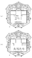
ここで、図5を参照して、第3図柄表示装置81の表示内容について説明する。図5は、第3図柄表示装置81の表示画面を説明するための図面であり、図5(a)は、表示画面の領域区分設定と有効ライン設定とを模式的に示した図であり、図5(b)は、実際の表示画面を例示した図である。
Here, with reference to FIG. 5, the display content of the 3rd
第3図柄は、「0」から「9」の数字を付した10種類の主図柄と、この主図柄より小さく形成された花びら形状の1種類の副図柄とにより構成されている。各主図柄は、木箱よりなる後方図柄の上に「0」から「9」の数字を付して構成され、そのうち奇数番号(1,3,5,7,9)を付した主図柄は、木箱の前面ほぼ一杯に大きな数字が付加されている。これに対し、偶数番号(0,2,4,6,8)を付した主図柄は、木箱の前面ほぼ一杯にお守り、風呂敷、ヘルメット等のキャラクタを模した付属図柄が付加されており、付属図柄の右下側に偶数の数字が緑色で小さく、且つ、付属図柄の前側に表示されるように付加されている。 The third symbol is composed of ten types of main symbols with numbers from “0” to “9” and one type of sub-shaped petal shape formed smaller than this main symbol. Each main symbol is composed of numbers from “0” to “9” on the rear symbol consisting of a wooden box, of which the main symbols with odd numbers (1, 3, 5, 7, 9) are A large number is added to almost the front of the wooden box. On the other hand, the main symbols with even numbers (0, 2, 4, 6, 8) are attached to the front of the wooden box almost fully, and attached symbols imitating characters such as furoshiki and helmets are added. An even number on the lower right side of the attached symbol is small in green and added so as to be displayed on the front side of the attached symbol.
また、本実施形態のパチンコ機10においては、主制御装置110による抽選結果が大当たりであった場合に、同一の主図柄が揃う変動表示が行われ、その変動表示が終わった後に大当たりが発生するよう構成されている。大当たり終了後に高確率状態(確変状態)に移行する場合は、奇数番号が付加された主図柄(「高確率図柄」に相当)が揃う変動表示が行われる。一方、大当たり終了後に低確率状態に移行する場合は、偶数番号が付加された主図柄(「低確率図柄」に相当)が揃う変動表示が行われる。ここで、高確率状態とは、大当たり終了後に付加価値としてその後の大当たり確率がアップした状態、いわゆる確率変動(確変)の時をいう。また、通常状態(低確率状態)とは、確変でない時をいい、大当たり確率が通常の状態、即ち、確変の時より大当たり確率が低い状態をいう。
Further, in the
第3図柄表示装置81の表示画面は、図5(a)に示すように、大きくは上下に2分割され、下側の2/3が第3図柄を変動表示する主表示領域Dm、それ以外の上側の1/3が予告演出やキャラクタを表示する副表示領域Dsとなっている。
As shown in FIG. 5 (a), the display screen of the third
主表示領域Dmには、左・中・右の3つの図柄列Z1,Z2,Z3が表示される。各図柄列Z1〜Z3には、前述した第3図柄が規定の順序で表示される。即ち、各図柄列Z1〜Z3には、数字の昇順または降順に主図柄が配列されると共に、各主図柄の間に副図柄が1つずつ配列されている。このため、各図柄列には、10個の主図柄と10個の副図柄の計20個の第3図柄が設定され、各図柄列Z1〜Z3毎に周期性をもって上から下へとスクロールして変動表示が行われる。特に、左図柄列Z1においては主図柄の数字が降順に現れるように配列され、中図柄列Z2及び右図柄列Z3においては主図柄の数字が昇順に現れるように配列されている。 In the main display area Dm, three symbol rows Z1, Z2, and Z3 of left, middle, and right are displayed. In each of the symbol rows Z1 to Z3, the above-described third symbols are displayed in a prescribed order. That is, in each symbol row Z1 to Z3, main symbols are arranged in ascending or descending numerical order, and one sub symbol is arranged between each main symbol. For this reason, a total of 20 third symbols of 10 main symbols and 10 sub-designs are set in each symbol row, and each symbol row Z1 to Z3 scrolls from top to bottom with periodicity. The display is changed. In particular, the left symbol row Z1 is arranged so that the numbers of the main symbols appear in descending order, and the middle symbol row Z2 and the right symbol row Z3 are arranged so that the numbers of the main symbols appear in ascending order.
また、主表示領域Dmには、各図柄列Z1〜Z3毎に上・中・下の3段に第3図柄が表示される。従って、第3図柄表示装置81には、3段×3列の計9個の第3図柄が表示される。この主表示領域Dmには、5つの有効ライン、即ち上ラインL1、中ラインL2、下ラインL3、右上がりラインL4、左上がりラインL5が設定されている。そして、毎回の遊技に際して、左図柄列Z1→右図柄列Z3→中図柄列Z2の順に変動表示が停止し、その停止時にいずれかの有効ライン上に大当たり図柄の組合せ(本実施の形態では、同一の主図柄の組合せ)で揃えば大当たりとして大当たり動画が表示される。
In the main display area Dm, the third symbols are displayed in the upper, middle, and lower three rows for each symbol row Z1 to Z3. Accordingly, the third
副表示領域Dsは、主表示領域Dmよりも上方に横長に設けられており、さらに左右方向に3つの予告領域Ds1〜Ds3に等区分されている。ここで、左右の予告領域Ds1,Ds3は、ソレノイドで電気的に開閉される両開き式の不透明な扉で通常覆われており、時としてソレノイドが励磁されて扉が手前側に開放されることにより遊技者に視認可能となる表示領域となっている。中央の予告領域Ds2は、扉で覆い隠されずに常に視認できる表示領域となっている。 The sub display area Ds is horizontally long above the main display area Dm, and is further equally divided into three notice areas Ds1 to Ds3 in the left-right direction. Here, the left and right notice areas Ds1, Ds3 are normally covered with a double-open opaque door that is electrically opened and closed by a solenoid, and sometimes the solenoid is excited and the door is opened to the front side. The display area is visible to the player. The center notice area Ds2 is a display area that is always visible without being covered by the door.
実際の表示画面では、図5(b)に示すように、主表示領域Dmに第3図柄の主図柄と副図柄とが合計9個表示される。副表示領域Dsにおいては、左右の扉が閉鎖された状態となっており、左右の予告領域Ds1,Ds3が覆い隠されて表示画面が視認できない状態となっている。変動表示の途中において、左右のいずれか一方、または両方の扉が開放されると、左右の予告領域Ds1,Ds3に動画が表示され、通常より大当たりへ遷移し易い状態であることが遊技者に示唆される。中央の予告領域Ds2では、通常は、所定のキャラクタ(本実施形態ではハチマキを付けた少年)が所定動作をし、時として所定動作とは別の特別な動作をしたり、別のキャラクタが現出する等して予告演出が行われる。なお、第3図柄表示装置81の表示画面は、原則として上下の表示領域Dm,Dsに区分されているが、各表示領域Dm,Dsを跨いでより大きく第3図柄やキャラクタ等を表示して表示演出を行うことができる。
On the actual display screen, as shown in FIG. 5B, a total of nine main symbols and sub-designs of the third symbol are displayed in the main display area Dm. In the sub display area Ds, the left and right doors are closed, and the left and right notice areas Ds1, Ds3 are covered and the display screen cannot be visually recognized. If either one of the left and right doors or both doors are opened during the variable display, a video is displayed in the left and right notice areas Ds1 and Ds3, and it is easy for the player to change to a big hit than usual. It is suggested. In the center notice area Ds2, a predetermined character (a boy with a bee in this embodiment) usually performs a predetermined action and sometimes performs a special action different from the predetermined action or another character appears. The announcement effect is performed by putting out. The display screen of the third
次に、上記の如く構成されたパチンコ機10の動作について説明する。本実施の形態では、主制御装置110内のMPU201は、遊技に際し各種カウンタ情報を用いて、大当たり抽選や第1図柄表示装置37の表示の設定などを行うこととしており、具体的には、図6に示すように、大当たりの抽選に使用する第1当たり乱数カウンタC1と、大当たり図柄の選択に使用する第1当たり種別図柄カウンタC2と、停止パターン選択カウンタC3と、第1当たり乱数カウンタC1の初期値設定に使用する第1初期値乱数カウンタCINI1と、変動パターン選択に使用する変動種別カウンタCS1,CS2,CS3とを用いることとしている。また、第2図柄表示装置82の抽選には第2当たり乱数カウンタC4が用いられ、第2当たり乱数カウンタC4の初期値設定には第2初期値乱数カウンタCINI2が用いられる。これら各カウンタは、更新の都度前回値に1が加算され、最大値に達した後0に戻るループカウンタとなっている。
Next, the operation of the
各カウンタは短時間間隔で更新され、その更新値がRAM203の所定領域に設定されたカウンタ用バッファに適宜格納される。RAM203には、1つの実行エリアと4つの保留エリア(保留第1〜第4エリア)とからなる保留球格納エリアが設けられており、これらの各エリアには、第1入球口64への球の入賞タイミングに合わせて、第1当たり乱数カウンタC1、第1当たり種別カウンタC2及び停止パターン選択カウンタC3の各値がそれぞれ格納される。
Each counter is updated at short time intervals, and the updated value is appropriately stored in a counter buffer set in a predetermined area of the
各カウンタについて詳しくは、第1当たり乱数カウンタC1は、例えば0〜738の範囲内で順に1ずつ加算され、最大値(つまり738)に達した後0に戻る構成となっている。特に第1当たり乱数カウンタC1が1周した場合、その時点の第1初期値乱数カウンタCINI1の値が当該第1当たり乱数カウンタC1の初期値として読み込まれる。なお、第1初期値乱数カウンタCINI1は、第1当たり乱数カウンタC1と同一範囲で更新されるループカウンタとして構成され(値=0〜738)、タイマ割込(図11参照)毎に1回更新されると共にメイン処理(図8参照)の残余時間内で繰り返し更新される。第1当たり乱数カウンタC1の値は、例えば定期的に(本実施の形態ではタイマ割込毎に1回)更新され、球が第1入球口64に入賞したタイミングでRAM203の保留球格納エリアに格納される。大当たりとなる乱数の値の数は、低確率時と高確率時とで2種類設定されており、低確率時に大当たりとなる乱数の値の数は2で、その値は「373,727」であり、高確率時に大当たりとなる乱数の値の数は14で、その値は「59,109,163,211,263,317,367,421,479,523,631,683,733」である。
Specifically, each counter is configured such that the first random number counter C1 is incremented by 1 in order, for example, within a range of 0 to 738, and returns to 0 after reaching the maximum value (ie, 738). In particular, when the first random number counter C1 makes one round, the value of the first initial value random number counter CINI1 at that time is read as the initial value of the first random number counter C1. The first initial value random number counter CINI1 is configured as a loop counter that is updated in the same range as the first per-random number counter C1 (value = 0 to 738), and is updated once every timer interrupt (see FIG. 11). And is repeatedly updated within the remaining time of the main process (see FIG. 8). The value of the first per-random number counter C1 is updated, for example, periodically (once every timer interruption in this embodiment), and the reserved ball storage area of the
第1当たり種別カウンタC2は、大当たりの際の第1図柄表示装置37の表示態様を決定するものであり、本実施の形態では、0〜4の範囲内で順に1ずつ加算され、最大値(つまり4)に達した後0に戻る構成となっている。第1当たり種別カウンタC2の値は、例えば定期的に(本実施の形態ではタイマ割込毎に1回)更新され、球が第1入球口64に入賞したタイミングでRAM203の保留球格納エリアに格納される。なお、大当たり後に高確率状態となる乱数の値は「1,2,3」であり、大当たり後に低確率状態となる乱数の値は「0,4」であり、2種類の当たり種別が決定される。よって、第1図柄表示装置37に表示される停止図柄に対応した表示態様は、高確率状態と低確率状態との2種類の大当たりに対応した表示態様と、はずれに対応した1種類の表示態様との合計3種類の表示態様のうち、いずれか1つが選択される。
The first hit type counter C2 determines the display mode of the first
停止パターン選択カウンタC3は、例えば0〜238の範囲内で順に1ずつ加算され、最大値(つまり238)に達した後0に戻る構成となっている。本実施の形態では、停止パターン選択カウンタC3によって、第3図柄表示装置81で表示される演出のパターンが選択され、リーチが発生した後最終停止図柄がリーチ図柄の前後に1つだけずれて停止する「前後外れリーチ」(例えば0〜8の範囲)と、同じくリーチ発生した後最終停止図柄がリーチ図柄の前後以外で停止する「前後外れ以外リーチ」(例えば9〜38の範囲)と、リーチ発生しない「完全外れ」(例えば39〜238の範囲)との3つの停止(演出)パターンが選択される。停止パターン選択カウンタC3の値は、例えば定期的に(本実施の形態ではタイマ割込毎に1回)更新され、球が第1入球口64に入賞したタイミングでRAM203の保留球格納エリアに格納される。
The stop pattern selection counter C3 is, for example, incremented by 1 in the range of 0 to 238, and returns to 0 after reaching the maximum value (that is, 238). In the present embodiment, the stop pattern selection counter C3 selects the effect pattern displayed on the third
また、停止パターン選択カウンタC3には、停止パターンの選択される乱数値の範囲が異なる複数のテーブルが設けられている。これは、現在のパチンコ機10の状態が高確率状態であるか低確率状態であるか、保留球格納エリアのどのエリアに各乱数値が格納されているか(即ち保留個数)等に応じて、停止パターンの選択比率を変更するためである。
Further, the stop pattern selection counter C3 is provided with a plurality of tables having different ranges of random number values from which the stop pattern is selected. This is based on whether the current state of the
例えば、高確率状態では、大当たりが発生し易いため必要以上にリーチ演出が選択されないように、「完全外れ」の停止パターンに対応した乱数値の範囲が10〜238と広いテーブルが選択され、「完全外れ」が選択され易くなる。このテーブルは、「前後外れリーチ」が0〜5と狭くなると共に「前後外れ以外リーチ」も6〜9と狭くなり、「前後外れリーチ」や「前後外れ以外リーチ」が選択され難くなる。また、低確率状態で保留球格納エリアに各乱数値が格納されていなければ、第1入球口64への球の入球時間を確保するために「完全外れ」の停止パターンに対応した乱数値の範囲が51〜238と狭いテーブルが選択され、「完全外れ」が選択され難くなる。このテーブルは、「前後外れ以外リーチ」の停止パターンに対応した乱数値の範囲が9〜50と広くなり、「前後外れ以外リーチ」が選択され易くなっている。よって、低確率状態では、第1入球口64への球の入球時間を確保できるので、第3図柄表示装置81による変動表示が継続して行われ易くなる。
For example, in a high probability state, a table with a wide random value range of 10 to 238 corresponding to the stop pattern of “completely out” is selected so that a jackpot is likely to occur and a reach effect is not selected more than necessary. It becomes easy to select “completely off”. In this table, “front / rear out of reach” is narrowed to 0-5, and “reach other than front / rear out of reach” is also narrowed to 6-9, making it difficult to select “rear out of front / rear out of reach” or “reach out of front / rear out of reach”. Further, if each random number value is not stored in the holding ball storage area in a low probability state, a disturbance corresponding to the stop pattern of “completely off” in order to secure the time for the ball to enter the
2つの変動種別カウンタCS1,CS2のうち、一方の変動種別カウンタCS1は、例えば0〜198の範囲内で順に1ずつ加算され、最大値(つまり198)に達した後0に戻る構成となっており、他方の変動種別カウンタCS2は、例えば0〜240の範囲内で順に1ずつ加算され、最大値(つまり240)に達した後0に戻る構成となっている。以下の説明では、CS1を「第1変動種別カウンタ」、CS2を「第2変動種別カウンタ」ともいう。 Of the two variation type counters CS1 and CS2, one variation type counter CS1 is incremented one by one within a range of 0 to 198, for example, and reaches a maximum value (that is, 198) and then returns to 0. On the other hand, the other variation type counter CS2 is, for example, incremented one by one within a range of 0 to 240, and returns to 0 after reaching the maximum value (that is, 240). In the following description, CS1 is also referred to as “first variation type counter”, and CS2 is also referred to as “second variation type counter”.
第1変動種別カウンタCS1によって、いわゆるノーマルリーチ、スーパーリーチ、プレミアムリーチ等の大まかな変動態様が決定される。変動態様の決定は、具体的には、図柄変動の変動時間の決定である。また、第2変動種別カウンタCS2によって、リーチ発生後に最終停止図柄(本実施の形態では中図柄)が停止するまでの変動時間(言い換えれば、変動図柄数)が決定される。変動種別カウンタCS1,CS2により決定された変動時間に基づいて、表示制御装置114により第3表示装置81で表示される第3図柄のリーチ種別や細かな図柄変動態様が決定される。従って、これらの変動種別カウンタCS1,CS2を組み合わせることで、変動パターンの多種多様化を容易に実現できる。また、第1変動種別カウンタCS1だけで図柄変動態様を決定したり、第1変動種別カウンタCS1と停止図柄との組み合わせで同じく図柄変動態様を決定したりすることも可能である。変動種別カウンタCS1,CS2の値は、後述するメイン処理(図8参照)が1回実行される毎に1回更新され、当該メイン処理内の残余時間内でも繰り返し更新される。
Rough fluctuation modes such as so-called normal reach, super reach, and premium reach are determined by the first fluctuation type counter CS1. The determination of the variation mode is specifically determination of the variation time of the symbol variation. Further, the second variation type counter CS2 determines a variation time (in other words, the number of variation symbols) until the final stop symbol (in the present embodiment, the middle symbol) stops after the occurrence of reach. Based on the variation time determined by the variation type counters CS1 and CS2, the
変動種別カウンタCS3の値は、例えば、0〜162の範囲内で順に1ずつ加算され、最大値(つまり162)に達した後に0に戻る構成となっている。以下の説明では、CS3を「第3変動種別カウンタ」ともいう。本実施の形態の第3図柄表示装置81は、第1図柄表示装置37の表示態様に応じた装飾的な演出を行うものであり、図柄の変動以外に、変動している図柄を滑らせたり、リーチ演出の発生を予告するための予告キャラクタを通過させるなどの予告演出が行われる。その予告演出の演出パターンが変動種別カウンタCS3により選択される。具体的には、予告演出に必要となる時間を変動時間に加算したり、反対に変動表示される時間を短縮するために変動時間を減算したり、変動時間を加減算しない演出パターンが選択される。なお、変動種別カウンタCS3は、停止パターン選択カウンタC3と同様に、演出パターンが選択される乱数値の範囲が異なる複数のテーブルが設けられ、現在のパチンコ機10の状態が高確率状態であるか低確率状態であるか、保留球格納エリアのどのエリアに各乱数値が格納されているか等に応じて、各演出パターンの選択比率が異なるよう構成されている。
For example, the value of the variation type counter CS3 is sequentially incremented by 1 within a range of 0 to 162, and returns to 0 after reaching the maximum value (that is, 162). In the following description, CS3 is also referred to as a “third variation type counter”. The 3rd
上述したように、変動種別カウンタCS1,CS2により図柄変動の変動時間が決定されると共に、変動種別カウンタCS3により変動時間に加減算される時間が決定される。よって、最終停止図柄が停止するまでの最終的な変動時間は、変動種別カウンタCS1,CS2,CS3により決定される。 As described above, the variation time of the symbol variation is determined by the variation type counters CS1 and CS2, and the time to be added to or subtracted from the variation time is determined by the variation type counter CS3. Therefore, the final fluctuation time until the final stop symbol stops is determined by the fluctuation type counters CS1, CS2, CS3.
第2当たり乱数カウンタC4は、例えば0〜250の範囲内で順に1ずつ加算され、最大値(つまり250)に達した後0に戻るループカウンタとして構成されている。第2当たり乱数カウンタC4の値は、本実施の形態ではタイマ割込毎に、例えば定期的に更新され、球が左右何れかの第2入球口(スルーゲート)67を通過したことが検知された時に取得される。当選することとなる乱数の値の数は149あり、その範囲は「5〜153」となっている。なお、第2初期値乱数カウンタCINI2は、第2当たり乱数カウンタC4と同一範囲で更新されるループカウンタとして構成され(値=0〜250)、タイマ割込(図11参照)毎に1回更新されると共にメイン処理(図8参照)の残余時間内で繰り返し更新される。 The second random number counter C4 is configured as a loop counter that is incremented one by one within a range of 0 to 250, for example, and returns to 0 after reaching the maximum value (that is, 250). In the present embodiment, the value of the second per-random number counter C4 is periodically updated, for example, every timer interruption, and it is detected that the ball has passed through either the left or right second entrance (through gate) 67. Get when it is done. The number of random number values to be won is 149, and the range is “5 to 153”. The second initial value random number counter CINI2 is configured as a loop counter that is updated in the same range as the second per-random number counter C4 (value = 0 to 250), and is updated once every timer interrupt (see FIG. 11). And is repeatedly updated within the remaining time of the main process (see FIG. 8).
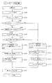
次に、図7から図13のフローチャートを参照して、主制御装置110内のMPU201により実行される各制御処理を説明する。かかるMPU201の処理としては大別して、電源投入に伴い起動される立ち上げ処理と、その立ち上げ処理後に実行されるメイン処理と、定期的に(本実施の形態では2ミリ秒(以下「ms」で表す)周期で)起動されるタイマ割込処理と、NMI端子への停電信号SG1の入力により起動されるNMI割込処理とがあり、説明の便宜上、はじめにタイマ割込処理とNMI割込処理とを説明し、その後立ち上げ処理とメイン処理とを説明する。
Next, each control process executed by the
図11は、タイマ割込処理を示したフローチャートである。タイマ割込処理は、主制御装置110のMPU201により例えば2ms毎に実行される。タイマ割込処理では、まず各種入賞スイッチの読み込み処理を実行する(S501)。即ち、主制御装置110に接続されている各種スイッチ(但し、RAM消去スイッチ122を除く)の状態を読み込むと共に、当該スイッチの状態を判定して検出情報(入賞検知情報)を保存する。次に、第1初期値乱数カウンタCINI1と第2初期値乱数カウンタCINI2の更新を実行する(S502)。具体的には、第1初期値乱数カウンタCINI1を1加算すると共に、そのカウンタ値が最大値(本実施の形態では738)に達した際0にクリアする。そして、第1初期値乱数カウンタCINI1の更新値を、RAM203の該当するバッファ領域に格納する。同様に、第2初期値乱数カウンタCINI2を1加算すると共に、そのカウンタ値が最大値(本実施の形態では250)に達した際0にクリアし、その第2初期値乱数カウンタCINI2の更新値をRAM203の該当するバッファ領域に格納する。
FIG. 11 is a flowchart showing the timer interrupt process. The timer interrupt process is executed by the
更に、第1当たり乱数カウンタC1、第1当たり種別カウンタC2、停止パターン選択カウンタC3及び第2当たり乱数カウンタC4の更新を実行する(S503)。具体的には、第1当たり乱数カウンタC1、第1当たり種別カウンタC2、停止パターン選択カウンタC3及び第2当たり乱数カウンタC4をそれぞれ1加算すると共に、それらのカウンタ値が最大値(本実施の形態ではそれぞれ、738,4,238,250)に達した際それぞれ0にクリアする。そして、各カウンタC1〜C4の更新値を、RAM203の該当するバッファ領域に格納する。
Further, the first per-random number counter C1, the first per-type counter C2, the stop pattern selection counter C3, and the second per-random number counter C4 are updated (S503). Specifically, 1 is added to each of the first per-random number counter C1, the first per-type counter C2, the stop pattern selection counter C3, and the second per-random number counter C4, and these counter values are the maximum values (this embodiment) Then, when 738, 4, 238, 250) are reached, they are cleared to 0. Then, the updated values of the counters C1 to C4 are stored in the corresponding buffer area of the
その後は、第1入球口64への入賞に伴う始動入賞処理を実行し(S504)、発射制御処理を実行して(S505)、タイマ割込処理を終了する。なお、発射制御処理は、遊技者が操作ハンドル51に触れていることをタッチセンサにより検出し、発射を停止させるための発射停止スイッチが操作されていないことを条件に、球の発射のオン/オフを決定する処理である。球の発射がオンである場合に、発射制御装置112に対して球の発射指示をする。
Thereafter, a start winning process is performed in accordance with winning at the first entrance 64 (S504), a firing control process is performed (S505), and the timer interrupt process is terminated. Note that the launch control process detects that the player is touching the operation handle 51 with a touch sensor and turns on / off the launch of the ball on the condition that the launch stop switch for stopping the launch is not operated. This is a process for determining OFF. When the launch of the sphere is on, the
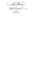
図12のフローチャートを参照して、S504の処理で実行される始動入賞処理を説明する。まず、球が第1入球口64に入賞(始動入賞)したか否かを判別する(S601)。球が第1入球口64に入賞したと判別されると(S601:Yes)、第1図柄表示装置37の作動保留球数Nが上限値(本実施の形態では4)未満であるか否かを判別する(S602)。第1入球口64への入賞があり、且つ作動保留球数N<4であれば(S602:Yes)、作動保留球数Nを1加算し(S603)、更に、前記ステップS503で更新した第1当たり乱数カウンタC1、第1当たり種別カウンタC2及び停止パターン選択カウンタC3の各値を、RAM203の保留球格納エリアの空き保留エリアのうち最初のエリアに格納する(S604)。一方、第1入球口64への入賞がないか(S601:No)、或いは、第1入球口64への入賞があっても作動保留球数N<4でなければ(S602:No)、S603及びS604の各処理をスキップし、始動入賞処理を終了してタイマ割込処理へ戻る。
The start winning process executed in the process of S504 will be described with reference to the flowchart of FIG. First, it is determined whether or not the ball has won (start winning) at the first entrance 64 (S601). If it is determined that the ball has won the first entrance 64 (S601: Yes), whether or not the number N of the operation reserved balls of the first
図13は、NMI割込処理を示したフローチャートである。NMI割込処理は、停電の発生等によるパチンコ機10の電源遮断時に、主制御装置110のMPU201により実行される処理である。このNMI割込処理により、電源断の発生情報がRAM203に記憶される。即ち、停電の発生等によりパチンコ機10の電源が遮断されると、停電信号SG1が停電監視回路252から主制御装置110内のMPU201のNMI端子に出力される。すると、MPU201は、実行中の制御を中断してNMI割込処理を開始し、電源断の発生情報の設定として、電源断の発生情報をRAM203に記憶し(S701)、NMI割込処理を終了する。
FIG. 13 is a flowchart showing the NMI interrupt process. The NMI interruption process is a process executed by the
なお、上記のNMI割込処理は、払出発射制御装置111でも同様に実行され、かかるNMI割込処理により、電源断の発生情報がRAM213に記憶される。即ち、停電の発生等によりパチンコ機10の電源が遮断されると、停電信号SG1が停電監視回路252から払出発射制御装置111内のMPU211のNMI端子に出力され、MPU211は実行中の制御を中断して、NMI割込処理を開始するのである。
The above NMI interrupt process is executed in the same manner in the payout and
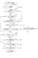
図7は、主制御装置110内のMPU201により実行される立ち上げ処理を示したフローチャートである。この立ち上げ処理は電源投入時のリセットにより起動される。立ち上げ処理では、まず、電源投入に伴う初期設定処理を実行する(S101)。具体的には、スタックポインタに予め決められた所定値を設定すると共に、サブ側の制御装置(音声ランプ制御装置113、払出制御装置111等)が動作可能な状態になるのを待つために、ウェイト処理(本実施の形態では1秒)を実行する。次いで、RAM203のアクセスを許可する(S103)。
FIG. 7 is a flowchart showing start-up processing executed by the
その後は、電源装置115に設けたRAM消去スイッチ122がオンされているか否かを判別し(S104)、オンされていれば(S104:Yes)、処理をS111へ移行する。一方、RAM消去スイッチ122がオンされていなければ(S104:No)、更にRAM203に電源断の発生情報が記憶されているか否かを判別し(S105)、記憶されていなければ(S105:No)、バックアップデータは記憶されていないので、この場合にも、処理をS111へ移行する。RAM203に電源断の発生情報が記憶されていれば(S105:Yes)、RAM判定値を算出し(S106)、算出したRAM判定値が正常でなければ(S107:No)、即ち算出したRAM判定値が電源遮断時に保存したRAM判定値と一致しなければ、バックアップされたデータは破壊されているので、かかる場合にも処理をS111へ移行する。なお、前述した通り、RAM判定値は、例えばRAM203の作業領域アドレスにおけるチェックサム値である。このRAM判定値に代えて、RAM203の所定のエリアに書き込まれたキーワードが正しく保存されているか否かによりバックアップの有効性を判断するようにしても良い。
Thereafter, it is determined whether or not the RAM erase
S111の処理では、RAM203の初期化が行われることを第3図柄表示装置81で表示させるために、音声ランプ制御装置113に対して初期化コマンドを送信する。その初期化コマンドの送信と同時に、主制御装置110の機種を識別するための機種判別コマンドが送信される。この機種判別コマンドは、主制御装置110が、○○物語M56に対応した制御装置か○○物語M3に対応した制御装置かを、判別可能なデータである。例えば、機種判別コマンドに含まれるデータの値が「0」であれば、○○物語M56用の主制御装置110であり、データの値が「1」であれば、○○物語M3用の主制御装置110が取り付けられていることになる。なお、以下の説明では、○○物語M56用の主制御装置が取り付けられている状態について説明する。
In the process of S111, an initialization command is transmitted to the sound
S111の処理で各コマンドが送信されると、サブ側の制御装置となる払出制御装置111を初期化するために払出初期化コマンドを送信する(S112)。その後、RAM203の初期化処理(S113、S114)に移行する。
When each command is transmitted in the process of S111, a payout initialization command is transmitted in order to initialize the
上述したように、本パチンコ機10では、例えばホールの営業開始時など、電源投入時にRAMデータを初期化する場合にはRAM消去スイッチ122を押しながら電源が投入される。従って、RAM消去スイッチ122が押されていれば、RAMの初期化処理(S113、S114)に移行する。また、電源断の発生情報が設定されていない場合や、RAM判定値(チェックサム値等)によりバックアップの異常が確認された場合も同様にRAM203の初期化処理に移行する。即ち、S113とS114のRAMの初期化処理では、RAM203の使用領域を0にクリアし(S113)、RAM203の初期値を設定する(S114)。その後、S115の処理へ移行する。
As described above, in the
一方、RAM消去スイッチ122がオンされておらず(S104:No)、電源遮断の発生情報が記憶されており(S105:Yes)、更にRAM判定値(チェックサム値等)が正常であれば(S107:Yes)、復電時の処理が行われることを第3図柄表示装置81で表示させるために、音声ランプ制御装置113に対して復電コマンドを送信する。その復電コマンドの送信と同時に、主制御装置110の機種を識別するための機種判別コマンドが送信される(S108)。なお、この機種判別コマンドは、S111の処理で送信される機種判別コマンドと同じものである。
On the other hand, if the RAM erase
S108の処理で各コマンドが送信されると、処理をS109へ移行して電源断の発生情報をクリアする(S109)。次に、サブ側の制御装置を駆動電源遮断時の遊技状態に復帰させるための復電時の払出復帰コマンドを送信し(S110)、S115の処理へ移行する。 When each command is transmitted in the process of S108, the process proceeds to S109 to clear the information on the occurrence of power interruption (S109). Next, a payout return command at the time of power recovery for returning the sub-side control device to the gaming state at the time of drive power interruption is transmitted (S110), and the process proceeds to S115.
S115の処理では、割込みを許可して、後述するメイン処理に移行する。 In the process of S115, an interrupt is permitted and the process proceeds to a main process described later.
次に、図8のフローチャートを参照してメイン処理を説明する。このメイン処理では遊技の主要な処理が実行される。その概要として、4ms周期の定期処理としてS201〜S206の各処理が実行され、その残余時間でS209,S210のカウンタ更新処理が実行される構成となっている。 Next, the main process will be described with reference to the flowchart of FIG. In this main process, the main process of the game is executed. As an outline, each process of S201 to S206 is executed as a periodic process with a period of 4 ms, and the counter update process of S209 and S210 is executed in the remaining time.
メイン処理においては、まず、前回の処理で更新されたコマンド等の出力データをサブ側の各制御装置に送信する(S201)。具体的には、入賞検知情報の有無を判別し、入賞検知情報があれば払出制御装置111に対して獲得球数に対応する賞球コマンドを送信する。また、第3図柄表示装置81による第3図柄の変動表示に必要な変動パターンコマンド、停止図柄コマンド、停止コマンド、演出時間加算コマンド等を音声ランプ制御装置113に送信する。さらに、球の発射を行う場合に、発射制御装置112に球発射信号を送信する。
In the main processing, first, output data such as a command updated in the previous processing is transmitted to each control device on the sub side (S201). Specifically, the presence / absence of winning detection information is determined, and if there is winning detection information, a winning ball command corresponding to the number of acquired balls is transmitted to the
次に、変動種別カウンタCS1,CS2,CS3の各値を更新する(S202)。具体的には、変動種別カウンタCS1,CS2,CS3を1加算すると共に、それらのカウンタ値が最大値(本実施の形態では198,240,162)に達した際それぞれ0にクリアする。そして、変動種別カウンタCS1,CS2,CS3の更新値を、RAM203の該当するバッファ領域に格納する。
Next, each value of the variation type counters CS1, CS2, CS3 is updated (S202). Specifically, the variation type counters CS1, CS2, CS3 are incremented by 1, and are cleared to 0 when their counter values reach the maximum value (198, 240, 162 in this embodiment). Then, the update values of the variation type counters
変動種別カウンタCS1,CS2,CS3の更新が終わると、払出制御装置111より受信した賞球計数信号や払出異常信号を読み込み(S203)、第1図柄表示装置37による表示を行うための処理や第3図柄表示装置81による第3図柄の変動パターンなどを設定する変動処理を実行する(S204)。なお、図柄変動処理の詳細は図9を参照して後述する。
When the update of the variation type counters CS1, CS2 and CS3 is completed, the winning ball counting signal and the payout abnormality signal received from the
変動処理の終了後は、大当たり状態である場合において可変入賞装置65の特定入賞口(大開放口)65aを開放又は閉鎖するための大開放口開閉処理を実行する(S205)。即ち、大当たり状態のラウンド毎に特定入賞口65aを開放し、特定入賞口65aの最大開放時間が経過したか、又は特定入賞口65aに球が規定数入賞したかを判定する。そして、これら何れかの条件が成立すると特定入賞口65aを閉鎖する。この特定入賞口65aの開放と閉鎖とを所定ラウンド数繰り返し実行する。
After the end of the variation process, a large opening opening / closing process for opening or closing the specific winning opening (large opening) 65a of the variable winning
次に、第2図柄表示装置82による第2図柄(例えば「○」又は「×」の図柄)の表示制御処理を実行する(S206)。簡単に説明すると、球が第2入球口(スルーゲート)67を通過したことを条件に、その通過したタイミングで第2当たり乱数カウンタC4の値が取得されると共に第2図柄表示装置82の表示部83にて第2図柄の変動表示が実施される。そして、第2当たり乱数カウンタC4の値により第2図柄の抽選が実施され、第2図柄の当たり状態になると、第1入球口64に付随する電動役物が所定時間開放される。
Next, a display control process of the second symbol (for example, the symbol “◯” or “x”) by the second
その後は、RAM203に電源断の発生情報が記憶されているか否かを判別し(S207)、RAM203に電源遮断の発生情報が記憶されていなければ(S207:No)、次のメイン処理の実行タイミングに至ったか否か、即ち前回のメイン処理の開始から所定時間(本実施の形態では4ms)が経過したか否かを判別し(S208)、既に所定時間が経過していれば(S208:Yes)、処理をS201へ移行し、前述したS201以降の各処理を繰り返し実行する。 Thereafter, it is determined whether or not information on occurrence of power interruption is stored in the RAM 203 (S207). If information on occurrence of power interruption is not stored in the RAM 203 (S207: No), the execution timing of the next main process is determined. It is determined whether or not a predetermined time (4 ms in the present embodiment) has elapsed since the start of the previous main process (S208). If the predetermined time has already elapsed (S208: Yes) ), The process proceeds to S201, and the processes after S201 described above are repeatedly executed.
一方、前回のメイン処理の開始から未だ所定時間が経過していなければ(S208:No)、所定時間に至るまでの、即ち次のメイン処理の実行タイミングに至るまでの残余時間内において、第1初期値乱数カウンタCINI1、第2初期値乱数カウンタCINI2及び変動種別カウンタCS1,CS2,CS3の更新を繰り返し実行する(S209,S210)。まず、第1初期値乱数カウンタCINI1と第2初期値乱数カウンタCINI2との更新を実行する(S209)。具体的には、第1初期値乱数カウンタCINI1と第2初期値乱数カウンタCINI2を1加算すると共に、そのカウンタ値が最大値(本実施の形態では738、250)に達した際0にクリアする。そして、第1初期値乱数カウンタCINI1と第2初期値乱数カウンタCINI2の更新値を、RAM203の該当するバッファ領域にそれぞれ格納する。次に、変動種別カウンタCS1,CS2,CS3の更新を実行する(S210)。具体的には、変動種別カウンタCS1,CS2,CS3を1加算すると共に、それらのカウンタ値が最大値(本実施の形態では198,240,162)に達した際それぞれ0にクリアする。そして、変動種別カウンタCS1,CS2,CS3の更新値を、RAM203の該当するバッファ領域にそれぞれ格納する。
On the other hand, if the predetermined time has not yet elapsed since the start of the previous main process (S208: No), the first time is within the remaining time until the predetermined time is reached, that is, until the next main process is executed. The initial value random number counter CINI1, the second initial value random number counter CINI2, and the variation type counters CS1, CS2, CS3 are repeatedly updated (S209, S210). First, the first initial value random number counter CINI1 and the second initial value random number counter CINI2 are updated (S209). Specifically, the first initial value random number counter CINI1 and the second initial value random number counter CINI2 are incremented by 1 and cleared to 0 when the counter value reaches the maximum value (738, 250 in this embodiment). . Then, the updated values of the first initial value random number counter CINI1 and the second initial value random number counter CINI2 are stored in the corresponding buffer areas of the
ここで、S201〜S206の各処理の実行時間は遊技の状態に応じて変化するため、次のメイン処理の実行タイミングに至るまでの残余時間は一定でなく変動する。故に、かかる残余時間を使用して第1初期値乱数カウンタCINI1と第2初期値乱数カウンタCINI2の更新を繰り返し実行することにより、第1初期値乱数カウンタCINI1と第2初期値乱数カウンタCINI2(即ち、第1当たり乱数カウンタC1の初期値、第2当たり乱数カウンタC4の初期値)をランダムに更新することができ、同様に変動種別カウンタCS1,CS2,CS3についてもランダムに更新することができる。 Here, since the execution time of each process of S201-S206 changes according to the state of the game, the remaining time until the next main process execution timing is not constant and varies. Therefore, by repeatedly performing the update of the first initial value random number counter CINI1 and the second initial value random number counter CINI2 using the remaining time, the first initial value random number counter CINI1 and the second initial value random number counter CINI2 (that is, , The initial value of the first per-random number counter C1 and the initial value of the second per-random number counter C4) can be updated at random. Similarly, the variation type counters CS1, CS2, and CS3 can be updated at random.
また、S207の処理において、RAM203に電源断の発生情報が記憶されていれば(S207:Yes)、S211以降の電源遮断時の処理が実行される。まず、各割込処理の発生を禁止し(S211)、電源が遮断されたことを示す電源遮断通知コマンドを他の制御装置(払出制御装置111や音声ランプ制御装置113など)に対して送信する(S212)。そして、RAM判定値を算出してその値を保存し(S213)、RAM203のアクセスを禁止して(S214)、電源が完全に遮断して処理が実行できなくなるまで無限ループを継続する。ここで、RAM判定値は、例えば、RAM203のバックアップされるスタックエリア及び作業エリアにおけるチェックサム値である。
Further, in the process of S207, if the occurrence information of power interruption is stored in the RAM 203 (S207: Yes), the process at the time of power interruption after S211 is executed. First, the generation of each interrupt process is prohibited (S211), and a power-off notification command indicating that the power has been cut off is transmitted to other control devices (such as the
なお、S207の処理は、S201〜S206で行われる遊技の状態変化に対応した一連の処理の終了時、又は、残余時間内に行われるS209とS210の処理の1サイクルの終了時となるタイミングで実行されている。よって、主制御装置110のメイン処理において、各設定が終わったタイミングで電源断の発生情報を確認しているので、電源遮断の状態から復帰する場合には立ち上げ処理の終了後S201の処理から開始される。即ち、立ち上げ処理において初期化された場合と同様にS201の処理から開始される。よって、電源遮断時の処理において、MPU201が使用している各レジスタの内容をスタックエリアへ退避したり、スタックポインタの値を保存しなくても、初期設定の処理(S101)において、スタックポインタが所定値(初期値)に設定されることで、S201の処理から開始できる。従って、主制御装置110の制御負担を軽減することができると共に、主制御装置110が誤動作したり暴走することなく正確な制御を行うことができる。また、データの記憶前に割込処理の発生を禁止(S211)するので、電源遮断時の処理(S212以降の処理)が開始された後にデータが更新されることを防止できる。また、各設定が終わったタイミングで電源断の処理が実行されるので、RAM203にバックアップする情報量を少なくすることができる。
Note that the processing of S207 is performed at the timing when the series of processing corresponding to the game state change performed in S201 to S206 is completed, or at the end of one cycle of the processing of S209 and S210 performed within the remaining time. It is running. Therefore, in the main process of the
次に、図9及び図10のフローチャートを参照して、変動処理(S204)を説明する。図柄変動処理では、まず、今現在大当たり中であるか否かを判別する(S301)。大当たり中としては、大当たりの際に第3図柄表示装置81で表示される大当たり遊技の最中と大当たり遊技終了後の所定時間の最中とが含まれる。判別の結果、大当たり中であれば(S301:Yes)、そのまま本処理を終了する。
Next, the variation process (S204) will be described with reference to the flowcharts of FIGS. In the symbol variation process, first, it is determined whether or not a big hit is currently being made (S301). The jackpot includes the jackpot game displayed on the third
大当たり中でなければ(S301:No)、第1図柄表示装置37の表示態様が変動中であるか否かを判別し(S302)、第1図柄表示装置37の表示態様が変動中でなければ(S302:No)、作動保留球数Nが0よりも大きいか否かを判別する(S303)。作動保留球数Nが0であれば(S303:No)、そのまま本処理を終了する。作動保留球数N>0であれば(S303:Yes)、作動保留球数Nを1減算し(S304)、保留球格納エリアに格納されたデータをシフト処理する(S305)。このデータシフト処理は、保留球格納エリアの保留第1〜第4エリアに格納されているデータを実行エリア側に順にシフトさせる処理であって、保留第1エリア→実行エリア、保留第2エリア→保留第1エリア、保留第3エリア→保留第2エリア、保留第4エリア→保留第3エリアといった具合に各エリア内のデータがシフトされる。データシフト処理の後は、第1図柄表示装置37の変動開始処理を実行する(S306)。なお、変動開始処理については図10を参照して後述する。
If it is not a big hit (S301: No), it is determined whether or not the display mode of the first
S302の処理において、第1図柄表示装置37の表示態様が変動中であると判別されると(S302:Yes)、変動時間が経過したか否かを判別する(S307)。第1図柄表示装置37の変動中の表示時間は、変動種別カウンタCS1,CS2により選択された変動パターンと変動種別カウンタCS3により選択された加算時間に応じて決められており、この変動時間が経過していなければ(S307:No)、第1図柄表示装置37の表示を更新する(S308)。本実施の形態では、第1図柄表示装置37のLED37aの内、変動が開始されてから変動時間が経過するまでは、例えば、現在点灯しているLEDが赤であれば、その赤のLEDを消灯すると共に緑のLEDを点灯させ、緑のLEDが点灯していれば、その緑のLEDを消灯すると共に青のLEDを点灯させ、青のLEDが点灯していれば、その青のLEDを消灯すると共に赤のLEDを点灯させる表示態様が設定される。なお、図柄変動処理は、0.4ms毎に実行されるが、その図柄変動処理毎にLEDの点灯色を変更すると、LEDの点灯色の変化を遊技者が確認することができない。そこで、遊技者にLEDの点灯色の変化を確認させるために、図柄変動処理は、実行される毎にカウンタ(図示せず)を1カウントし、そのカウンタが100に達した場合に、LEDの点灯色の変更を行い、0.4s毎にLEDの点灯色の変更を行っている。なお、カウンタの値は、LEDの点灯色が変更されたらリセット(値0)される。
In the process of S302, if it is determined that the display mode of the first
一方、第1図柄表示装置37の変動時間が経過していれば(S307:Yes)、第1図柄表示装置37の停止図柄に対応した表示態様が設定される(S309)。停止図柄の設定は、第1当たり乱数カウンタC1の値に応じて大当たりか否かが決定されると共に、大当たりである場合には第1当たり種別カウンタC2の値により大当たり後に高確率状態となる図柄か低確率状態となる図柄かが決定される。本実施の形態では、大当たり後に高確率状態になる場合には赤色のLEDを点灯させ、低確率状態になる場合には緑色のLEDを点灯させ、外れである場合には青色のLEDを点灯させる。なお、各LEDの表示は、次の変動表示が開始される場合に点灯が解除されるが、変動の停止後数秒間のみ点灯させるものとしても良い。
On the other hand, if the variation time of the first
S309の処理で停止図柄に対応した第1図柄表示装置37の表示態様が設定されると、第3図柄表示装置81の変動停止を第1図柄表示装置37におけるLEDの点灯と同調させるために停止コマンドが設定される(S310)。この停止コマンドを音声ランプ制御装置113が受信して表示制御装置114に停止指示をする。第3図柄表示装置81は、変動時間が経過すると変動が停止し、停止コマンドを受信することで、第3図柄表示装置81における1の変動演出が終了する。
When the display mode of the first
次に、図10のフローチャートを参照して、変動開始処理を説明する。変動開始処理(S306)では、まず、保留球格納エリアの実行エリアに格納されている第1当たり乱数カウンタC1の値に基づいて大当たりか否かを判別する(S401)。大当たりか否かは第1当たり乱数カウンタ値とその時々のモードとの関係に基づいて判別される。前述した通り通常の低確率時には第1当たり乱数カウンタC1の数値0〜738のうち「373,727」が当たり値であり、高確率時には「59,109,163,211,263,317,367,421,479,523,631,683,733」が当たり値である。
Next, the variation start process will be described with reference to the flowchart of FIG. In the variation start process (S306), first, it is determined whether or not a big hit is made based on the value of the first hit random number counter C1 stored in the execution area of the reserved ball storage area (S401). Whether it is a big hit is determined based on the relationship between the first random number counter value and the mode at that time. As described above, “373,727” is a winning value among the
大当たりであると判別された場合(S401:Yes)、保留球格納エリアの実行エリアに格納されている第1当たり種別カウンタC2の値を確認して、大当たり時の表示態様が設定される(S402)。S402の処理では、第1当たり種別カウンタC2の値に基づき、大当たり後に高確率状態に移行するか低確率状態に移行するかが設定される。大当たり後の移行状態が設定されると、第1図柄表示装置37の表示態様(LED37aの点灯状態)が設定される。また、大当たり後の移行状態に基づいて、第3図柄表示装置81の大当たりの停止図柄が表示制御装置114で設定される。即ち、S402の処理で、大当たり後の移行状態を設定することで、第3図柄表示装置81における停止図柄を設定できる。なお、第1当たり種別カウンタC2の数値0〜4のうち、「0,4」の場合は以後低確率状態に移行し、「1,2,3」の場合は高確率状態に移行する。
When it is determined that it is a big hit (S401: Yes), the value of the first hit type counter C2 stored in the execution area of the reserved ball storage area is confirmed, and the display mode for the big hit is set (S402). ). In the process of S402, based on the value of the first hit type counter C2, whether to shift to the high probability state or shift to the low probability state after the big hit is set. When the transition state after the big hit is set, the display mode of the first symbol display device 37 (the lighting state of the
次に、大当たり時の変動パターンを決定する(S403)。S403の処理で変動パターンが設定されると、第1図柄表示装置37の表示時間が設定されると共に、第3図柄表示装置81において大当たり図柄で停止するまでの第3図柄の変動時間が決定される。このとき、RAM203のカウンタ用バッファに格納されている変動種別カウンタCS1,CS2の値を確認し、第1変動種別カウンタCS1の値に基づいてノーマルリーチ、スーパーリーチ、プレミアムリーチ等の大まかな図柄変動の変動時間を決定すると共に、第2変動種別カウンタCS2の値に基づいてリーチ発生後に最終停止図柄(本実施の形態では中図柄Z2)が停止するまでの変動時間(言い換えれば、変動図柄数)を決定する。
Next, a variation pattern at the time of jackpot is determined (S403). When the variation pattern is set in the process of S403, the display time of the first
なお、第1変動種別カウンタCS1の数値と変動時間との関係、第2変動種別カウンタCS2の数値と変動時間との関係は、それぞれにテーブル等により予め規定されている。但し、上記変動時間は、第2変動種別カウンタCS2の値を使わずに第1変動種別カウンタCS1の値だけを用いて設定することも可能であり、第1変動種別カウンタCS1の値だけで設定するか又は両変動種別カウンタCS1,CS2の両値で設定するかは、その都度の第1変動種別カウンタCS1の値や遊技条件などに応じて適宜決められる。 The relationship between the numerical value of the first variation type counter CS1 and the variation time, and the relationship between the numerical value of the second variation type counter CS2 and the variation time are respectively defined in advance by a table or the like. However, the fluctuation time can be set using only the value of the first fluctuation type counter CS1 without using the value of the second fluctuation type counter CS2, and can be set only with the value of the first fluctuation type counter CS1. Whether or not to set with both values of both variation type counters CS1 and CS2 is appropriately determined according to the value of the first variation type counter CS1 and the game conditions each time.
S401の処理で大当たりではないと判別された場合には(S401:No)、外れ時の表示態様が設定される(S404)。S404の処理では、第1図柄表示装置37の表示態様を外れ図柄に対応した表示態様に設定すると共に、保留球格納エリアの実行エリアに格納されている停止パターン選択カウンタC3の値に基づいて、第3図柄表示装置81において表示させる演出を、前後外れリーチであるか、前後外れ以外リーチであるか、完全外れであるかを設定する。本実施の形態では、上述したように、高確率状態であるか、低確率状態であるか、及び作動保留個数Nに応じて、停止パターン選択カウンタC3の各停止パターンに対応する値の範囲が異なるようテーブルが設定されている。
If it is determined in the process of S401 that it is not a big hit (S401: No), the display mode at the time of disconnection is set (S404). In the process of S404, the display mode of the first
次に、外れ時の変動パターンが決定され(S405)、第1図柄表示装置37の表示時間が設定されると共に、第3図柄表示装置81において外れ図柄で停止するまでの第3図柄の変動時間が決定される。このとき、S403の処理と同様に、RAM203のカウンタ用バッファに格納されている変動種別カウンタCS1,CS2の値を確認し、第1変動種別カウンタCS1の値に基づいてノーマルリーチ、スーパーリーチ、プレミアムリーチ等の大まかな図柄変動の変動時間を決定すると共に、第2変動種別カウンタCS2の値に基づいてリーチ発生後に最終停止図柄(本実施の形態では中図柄Z2)が停止するまでの変動時間(言い換えれば、変動図柄数)を決定する。
Next, the variation pattern at the time of detachment is determined (S405), the display time of the first
S403の処理またはS405の処理が終わると、第1及び第2種別カウンタCS1,CS2により決定された変動時間に加減算される演出時間が決定される(S406)。このとき、RAM203のカウンタ用バッファに格納されている第3種別カウンタCS3の値に基づいて演出時間の加減算が決定され、第1図柄表示装置37の表示時間が設定されると共に、第3図柄表示装置81の変動時間が設定される。本実施の形態では、演出時間の加減算の決定は、第3変動種別カウンタCS3の値に応じて、変動表示の時間を変更しない場合と変動表示時間を1秒加算する場合、変動表示時間を2秒加算する場合、変動表示時間を1秒減算する場合との4種類の加算値が決定される。
When the process of S403 or the process of S405 is completed, the effect time to be added to or subtracted from the variation time determined by the first and second type counters CS1 and CS2 is determined (S406). At this time, the addition / subtraction of the presentation time is determined based on the value of the third type counter CS3 stored in the counter buffer of the
なお、変動表示時間が加減算される場合には、第3図柄表示装置81で大当たりの期待値が高くなる予告演出(例えば、変動図柄の変動時間を通常より長くしてスベリを伴わせるスベリ演出や予告キャラを表示させる演出、1の変動図柄の変動時間を通常より短くして即停止させる演出など)が行われる。また、第1当たり乱数カウンタC1の値が大当たりである場合は、2秒の加算値が選択される確率が高く設定されているので、遊技者は予告演出を確認することで大当たりを期待することができる。 In addition, when the variable display time is added or subtracted, a notice effect that increases the expected value of the jackpot on the third symbol display device 81 (for example, a slip effect that causes the change time of the variable symbol to be longer than usual and is accompanied by a slip) An effect of displaying a notice character is produced, for example, an effect of making the change time of one change symbol shorter than usual and stopping it immediately). In addition, when the value of the first random number counter C1 is a big hit, the probability that an added value of 2 seconds is selected is set high, so that the player expects a big hit by confirming the notice effect. Can do.
次に、S403又はS405の処理で決定された変動パターン(変動時間)に応じて変動パターンコマンドを設定し(S407)、S402又はS404の処理で設定された停止図柄に応じて停止図柄コマンドを設定する(S408)。そして、S406の処理で決定された演出時間の加算値に応じて演出時間加算コマンドを設定して(S409)、図柄変動処理へ戻る。 Next, a variation pattern command is set according to the variation pattern (variation time) determined in the process of S403 or S405 (S407), and a stop symbol command is set according to the stop symbol set in the process of S402 or S404. (S408). Then, an effect time addition command is set according to the added value of the effect time determined in the process of S406 (S409), and the process returns to the symbol variation process.
次に、図14及び図15を参照して、払出制御装置111内のMPU211により実行される払出制御について説明する。図14は、払出制御装置111の立ち上げ処理を示したフローチャートであり、この立ち上げ処理は電源投入時に起動される。まず、電源投入に伴う初期設定処理を実行する(S801)。具体的には、スタックポインタに予め決められた所定値を設定すると共に、割込みモードを設定する。そして、RAMアクセスを許可すると共に(S802)、外部割込ベクタの設定を行う(S803)。
Next, payout control executed by the
その後は、MPU211内のRAM213に関してデータバックアップの処理を実行する。具体的には、RAM213に電源断の発生情報が記憶されているか否かを判別し(S804)、記憶されていなければ(S804:No)、バックアップデータは記憶されていないので、処理をS812へ移行する。RAM213に電源断の発生情報が記憶されていれば(S804:Yes)、RAM判定値を算出し(S805)、算出したRAM判定値が正常でなければ(S805:No)、即ち算出したRAM判定値が電源遮断時に保存したRAM判定値と一致しなければ、バックアップされたデータは破壊されているので、かかる場合にも処理をS810へ移行する。なお、前述した通り、RAM判定値は、例えばRAM213の作業領域アドレスにおけるチェックサム値である。このRAM判定値に代えて、RAM213の所定のエリアに書き込まれたキーワードが正しく保存されているか否かによりバックアップの有効性を判断するようにしても良い。
After that, data backup processing is executed for the
S810の処理〜S812の処理のRAMの初期化処理では、RAM213の全ての領域を0にクリアし(S810)、RAM213の初期値を設定する(S811)。その後、MPU211周辺デバイスの初期設定を行い(S812)、S813の処理へ移行し割込みを許可してメイン処理へ移行する。
In the RAM initialization process from S810 to S812, all areas of the
一方、電源断の発生情報が設定されており(S804:Yes)、且つRAM判定値(チェックサム値等)が正常であれば(S806:Yes)、復電時の処理(電源遮断復旧時の処理)を実行する。即ち、電源遮断の発生情報をクリアすると共に(S807)、賞球の払出を許可する払出許可フラグをクリアする(S808)。また、MPU211周辺デバイスの初期設定を行い(S809)、S813の処理へ移行し割込みを許可してメイン処理へ移行する。
On the other hand, if the power-off occurrence information is set (S804: Yes) and the RAM judgment value (checksum value etc.) is normal (S806: Yes), the process at the time of power recovery (at the time of power-off restoration) Process). That is, the information on occurrence of power interruption is cleared (S807), and the payout permission flag for permitting the payout of prize balls is cleared (S808). Also, the
次に、図15のフローチャートを参照して、払出制御装置111内のMPU211により実行されるメイン処理を説明する。このメイン処理は、まず主制御装置110からの賞球コマンドや発射制御装置112へ送信されるコマンドなどを取得し、そのコマンドの判定処理を行う(S901)。コマンド判定処理では、主制御装置110から送信されるコマンド(払出初期化コマンド、払出復電コマンド、賞球コマンドなど)を受信すると払出許可フラグがオンされ払い出しが許可される。
Next, the main process executed by the
コマンド判定処理(S901)が終わると、払い出しが許可されているか否かが判別され(S902)、払い出しが許可されていなければ(S902:No)、コマンド判定処理(S901)において払い出しが許可されるまでコマンド判定処理(S901)を繰り返し実行する。一方、S902の処理において払い出しが許可されていれば(S902:Yes)、状態復帰スイッチ120をチェックし状態復帰動作開始と判定した場合に状態復帰動作を実行する(S903)。
When the command determination process (S901) ends, it is determined whether or not the payout is permitted (S902). If the payout is not permitted (S902: No), the payout is permitted in the command determination process (S901). Until the command determination process (S901) is repeated. On the other hand, if the payout is permitted in the process of S902 (S902: Yes), the state return operation is executed when the
その後、下皿301の状態の変化に応じて下皿満タン状態又は下皿満タン解除状態の設定を実行する(S904)。即ち、下皿満タンスイッチの検出信号により下皿50の満タン状態を判別し、下皿満タンになった時に、下皿満タン状態の設定を実行し、下皿満タンでなくなった時に、下皿満タン解除状態の設定を実行する。また、タンク球の状態の変化に応じてタンク球無し状態又はタンク球無し解除状態の設定を実行する(S905)。即ち、タンク球無しスイッチの検出信号によりタンク球無し状態を判別し、タンク球無しになった時に、タンク球無し状態の設定を実行し、タンク球無しでなくなった時に、タンク球無し解除状態の設定を実行する。その後、報知する状態の有無を判別し、報知する状態が有る場合には払出制御装置111に設けた7セグメントLEDにより報知する(S906)。
Thereafter, the setting of the lower plate full state or the lower plate full state is executed according to the change in the state of the lower plate 301 (S904). That is, when the
次に、S907〜S909の各処理により、賞球払出の処理を実行する。即ち、賞球の払出不可状態でなく且つ記憶した総賞球個数が0でなければ(S907:No,S908:No)、賞球の払い出しを行うために賞球制御処理を開始する(S909)。一方、賞球の払出不可状態(S907:Yes)または総賞球個数が0であれば(S908:Yes)、貸球払出の処理に移行する。 Next, a winning ball payout process is executed by each process of S907 to S909. That is, if the prize ball is not in a payout disabled state and the total number of prize balls stored is not 0 (S907: No, S908: No), a prize ball control process is started in order to pay out the prize ball (S909). . On the other hand, if the prize ball cannot be paid out (S907: Yes) or if the total number of prize balls is 0 (S908: Yes), the process proceeds to the lending and payout process.
S910〜S912の貸球払出の処理では、貸球の払出不可状態でなく且つカードユニットからの貸球払出要求を受信していれば(S910:No,S911:Yes)、貸球を払い出しために貸球制御処理を開始する。一方、貸球の払出不可状態(S910:Yes)または貸球払出要求を受信していない場合(S911:No)、S912の処理が終わった場合には、球詰まり状態であることを条件にバイブレータ134の制御(バイブモータ制御)を実行する(S913)。 In the lending process of S910 to S912, if the lending is not disabled and a lending payout request from the card unit has been received (S910: No, S911: Yes), The lending control process is started. On the other hand, when the rental ball cannot be paid out (S910: Yes) or when the rental ball payout request has not been received (S911: No), when the processing of S912 is completed, the vibrator is conditioned on the condition that the ball is jammed. The control of 134 (vibrating motor control) is executed (S913).
その後は、RAM213に電源断の発生情報が記憶されているか否かを判別し(S914)、電源断の発生情報が記憶されていなければ(S914:No)、S901の処理へ戻りメイン処理を繰り返し実行する。 Thereafter, it is determined whether or not occurrence information of power interruption is stored in the RAM 213 (S914). If no occurrence information of power interruption is stored (S914: No), the process returns to S901 and repeats the main process. Execute.
一方、S914の処理において、電源断の発生情報が記憶されていれば(S914:Yes)、電源が遮断されたことになるので、各割込処理の発生の禁止をし(S915)、主制御装置110から送信されるコマンドの受信漏れを防止するために再度コマンド判定処理を実行する(S916)。そして、RAM判定値を算出してRAM213に保存し(S917)、RAM213のアクセスを禁止して(S918)、電源が完全に遮断して処理が実行できなくなるまで無限ループを継続する。ここで、例えば、RAM判定値は、RAM213のバックアップされるスタックエリア及び作業エリアにおけるチェックサム値である。
On the other hand, if the information on the occurrence of power interruption is stored in the process of S914 (S914: Yes), the power supply is shut off, so the generation of each interrupt process is prohibited (S915), and the main control is performed. Command determination processing is executed again in order to prevent omission of reception of commands transmitted from the device 110 (S916). Then, the RAM determination value is calculated and stored in the RAM 213 (S917), access to the
なお、S912の処理は、払出制御装置111のメイン処理の1サイクルが終わるタイミングで電源断の発生情報を確認しているので、電源遮断前の状態から復帰する場合には立ち上げ処理の終了後S901の処理から開始される。即ち、立ち上げ処理において初期化された場合と同様にS901の処理から開始される。よって、電源遮断時の処理において、MPU211が使用している各レジスタの内容をスタックエリアへ退避したり、スタックポインタの値を保存しなくても、初期設定の処理(S801)において、スタックポインタが所定値(初期値)に設定されることで、S901の処理から開始できる。従って、払出制御装置111の制御負担を軽減することができると共に、払出制御装置111が誤動作したり暴走することなく正確な制御を行うことができる。また、各処理が終わったタイミングで電源断の処理が実行されるので、RAM213にバックアップする情報量を少なくすることができる。
In the process of S912, the occurrence information of the power supply interruption is confirmed at the timing when one cycle of the main process of the
次に、音声ランプ制御装置113で行われる処理について図16及び図17を参照して説明する。図16は、音声ランプ制御装置113内のMPU221により実行される立ち上げ処理を示したフローチャートであり、この立ち上げ処理は電源投入時に起動される。
Next, processing performed by the sound
まず、電源投入に伴う初期設定処理を実行する(S1001)。具体的には、スタックポインタに予め決められた所定値を設定する。その後、電源断処理中フラグがオンしているか否かによって、今回の立ち上げ処理が瞬間的な電圧降下(瞬間的な停電、所謂「瞬停」)によって、S1115の電源断処理の実行途中に開始されたものであるか否かが判断される(S1002)。図17を参照して後述する通り、音声ランプ制御装置113は、主制御装置110から電源断コマンドを受信すると(図17のS1112参照)、S1115の電源断処理を実行する。かかる電源断処理の実行前に、電源断処理中フラグがオンされ、該電源断処理の終了後に、電源断処理中フラグはオフされる。よって、S1115の電源断処理が実行途中であるか否かは、電源断処理中フラグの状態によって判断できる。
First, initial setting processing accompanying power-on is executed (S1001). Specifically, a predetermined value set in advance for the stack pointer is set. Thereafter, depending on whether or not the power-off processing flag is turned on, the current start-up processing is performed during the execution of the power-off processing of S1115 due to an instantaneous voltage drop (instant power failure, so-called “instantaneous power failure”) It is determined whether it has been started (S1002). As will be described later with reference to FIG. 17, when the sound
電源断処理中フラグがオフであれば(S1002:No)、今回の立ち上げ処理は、電源が完全に断された後に開始されたか、瞬間的な停電が生じた後であってS1115の電源断処理の実行を完了した後に開始されたか、或いは、ノイズなどによって音声ランプ制御装置113のMPU221にのみリセットがかかって(主制御装置110からの電源断コマンドを受信することなく)開始されたものである。よって、これらの場合には、RAM223のデータが破壊されているか否かを確認する(S1003)。
If the power-off process flag is off (S1002: No), the current start-up process is started after the power supply is completely turned off or after a momentary power failure occurs and the power-off process at S1115 is performed. It was started after the execution of the process was completed, or started only after the
RAM223のデータ破壊の確認は、次のように行われる。即ち、RAM223の特定の領域には、S1006の処理によって「55AAh」のキーワードとしてのデータが書き込まれている。よって、その特定領域に記憶されるデータをチェックし、該データが「55AAh」であればRAM223のデータ破壊は無く、逆に「55AAh」でなければRAM223のデータ破壊を確認することができる。RAM223のデータ破壊が確認されれば(S1003:Yes)、S1004へ移行して、RAM223の初期化を開始する。一方、RAM223のデータ破壊が確認されなければ(S1003:No)、S1008へ移行する。
Confirmation of data destruction of the
なお、今回の立ち上げ処理が電源が完全に断された後に開始された場合には、RAM223の特定領域に「55AAh」のキーワードは記憶されていないので(電源断によってRAM223の記憶は喪失するから)、RAM22のデータ破壊と判断され(S1003:Yes)、S1004へ移行する。一方、今回の立ち上げ処理が、瞬間的な停電が生じた後であってS1115の電源断処理の実行を完了した後に開始されたか、或いは、ノイズなどによって音声ランプ制御装置113のMPU221にのみリセットがかかって開始された場合には、RAM223の特定領域には「55AAh」のキーワードが記憶されているので、RAM22のデータは正常と判断されて(S1003:No)、S1008へ移行する。
If the current startup process is started after the power is completely turned off, the keyword “55AAh” is not stored in the specific area of the RAM 223 (because the memory is lost in the
電源断処理中フラグがオンであれば(S1002:Yes)、今回の立ち上げ処理は、瞬間的な停電が生じた後であって、S1115の電源断処理の実行途中に、音声ランプ制御装置113のMPU221にリセットがかかって開始されたものである。かかる場合は電源断処理の実行途中なので、RAM223の記憶状態は必ずしも正しくない。よって、かかる場合には制御を継続することはできないので、処理をS1004へ移行して、RAM223の初期化を開始する。
If the power-off process flag is on (S1002: Yes), the startup process of this time is after an instantaneous power failure, and during the execution of the power-off process of S1115, the sound
S1004の処理では、RAM223の全範囲の記憶領域をチェックする(S1004)。チェック方法としては、まず、1バイト毎に「0FFh」を書き込み、それを1バイト毎に読み出して「0FFh」であるか否かを確認し、「0FFh」であれば正常と判別する。かかる1バイト毎の書き込み及び確認を、「0FFh」に次いで、「55h」、「0AAh」、「00h」の順に行う。このRAM223の読み書きチェックにより、RAM223のすべての記憶領域が0クリアされる。
In the processing of S1004, the entire storage area of the
RAM223のすべての記憶領域について、読み書きチェックが正常と判別されれば(S1005:Yes)、RAM223の特定領域に「55AAh」のキーワードを書き込んで、RAM破壊チェックデータを設定する(S1006)。この特定領域に書き込まれた「55AAh」のキーワードを確認することにより、RAM223にデータ破壊があるか否かがチェックされる。一方、RAM223のいずれかの記憶領域で読み書きチェックの異常が検出されれば(S1005:No)、RAM223の異常を報知して(S1007)、電源が遮断されるまで無限ループする。RAM223の異常は、表示ランプ34により報知される。なお、音声出力装置226により音声を出力してRAM223の異常報知を行うようにしても良い。
If it is determined that the read / write check is normal for all the storage areas of the RAM 223 (S1005: Yes), the keyword “55AAh” is written in the specific area of the
S1008の処理では、電源断フラグがオンされているか否かを判別する(S1008)。電源断フラグはS1115の電源断処理の実行時にオンされるので(図17のS1114参照)、電源断フラグがオンされた状態でS1008の処理に至るのは、今回の立ち上げ処理が、瞬間的な停電が生じた後であってS1115の電源断処理を実行した後に開始された場合である。従って、かかる場合には(S1008:Yes)、音声ランプ制御装置113の各処理を初期化するためにRAMの作業エリアをクリアし(S1009)、RAM223の初期値を設定した後(S1010)、割込み許可を設定して(S1011)、メイン処理へ移行する。なお、RAM223の作業エリアとしては、主制御装置110から受信したコマンド等を記憶する領域以外の領域をいう。
In the process of S1008, it is determined whether or not the power-off flag is turned on (S1008). Since the power-off flag is turned on when the power-off process in S1115 is executed (see S1114 in FIG. 17), the current start-up process is instantaneous when the power-off flag is turned on. This is a case where the process is started after a power failure has occurred and the power-off process in S1115 has been executed. Therefore, in such a case (S1008: Yes), the RAM work area is cleared to initialize each process of the sound lamp control device 113 (S1009), and the initial value of the
一方、電源断フラグがオフされた状態でS1008の処理に至るのは、今回の立ち上げ処理が、例えば電源が完全に断された後に開始されたためにS1004からS1006の処理を経由してS1008の処理へ至ったか、或いは、ノイズなどによって音声ランプ制御装置113のMPU221にのみリセットがかかって(主制御装置110からの電源断コマンドを受信することなく)開始された場合である。よって、かかる場合には(S1008:No)、RAM223の作業領域のクリア処理であるS1009をスキップして、処理をS1010へ移行し、RAM223の初期値を設定した後(S1010)、割込み許可を設定して(S1011)、メイン処理へ移行する。
On the other hand, the process of S1008 is reached with the power-off flag turned off because the current start-up process is started after the power supply has been completely shut down, for example, through the processes of S1004 to S1006. This is a case where the processing has been reached, or the
なお、S1009のクリア処理をスキップするのは、S1004からS1006の処理を経由してS1008の処理へ至った場合には、S1004の処理によって、既にRAM223のすべての記憶領域はクリアされているし、ノイズなどによって音声ランプ制御装置113のMPU221にのみリセットがかかって、立ち上げ処理が開始された場合には、RAM223の作業領域のデータをクリアせず保存しておくことにより、音声ランプ制御装置113の制御を継続できるからである。
The reason for skipping the clear process of S1009 is that when the process from S1004 to S1006 is reached via the process of S1006, all the storage areas of the
次に、図17を参照して、MPU221により実行されるメイン処理を説明する。まず、メイン処理が開始されてから1ms以上が経過したか否かが判別され(S1101)、1ms以上経過していなければ(S1101:No)、S1102〜S1109の処理を行わずにS1110の処理へ移行する。S1101の処理で、1ms経過したか否かを判別するのは、S1102〜S1109が表示(演出)に関する処理であり、短い周期(1ms以内)で編集する必要がないのに対して、S1110の各カウンタの更新処理やS1111のコマンドの受信処理を短い周期で実行する方が好ましいからである。これにより、主制御装置110から送信されるコマンドの受信洩れを防止できる。
Next, a main process executed by the
S1101の処理で1ms以上経過していれば(S1101:Yes)、表示ランプ34の点灯態様の設定や後述するS1107の処理で編集されるランプの点灯態様となるよう各ランプの出力を設定し(S1102)、その後電源投入報知処理を実行する(S1103)。電源投入報知処理は、電源が投入された場合に所定の時間(例えば30秒)電源が投入されたことを知らせる報知を行うものであり、その報知は音声出力装置226やランプ表示装置227により行われる。また、第3図柄表示装置81の画面において電源が供給されたことを報知するようコマンドを表示制御装置114に送信するものとしても良い。なお、電源投入時でなければ、電源投入報知処理による報知は行われずにS1104の処理へ移行する。
If 1 ms or more has elapsed in the processing of S1101 (S1101: Yes), the output of each lamp is set so as to set the lighting mode of the
S1104の処理では客待ち演出が実行され、その後、保留個数表示更新処理が実行される(S1105)。客待ち演出では、パチンコ機10が遊技者により遊技されない時間が所定時間経過した場合に、第3図柄表示装置81の表示をタイトル画面に切り替える設定などが行われ、その設定がコマンドとして表示制御装置114に送信される。保留個数表示更新処理では、作動保留球Nに応じて保留ランプ85を点灯させる処理が行われる。
In the process of S1104, a waiting-for-customer effect is executed, and then a hold number display update process is executed (S1105). In the customer waiting effect, when a time during which the
その後、枠ボタン入力監視・演出処理が実行される(S1106)。この枠ボタン入力監視・演出処理では、演出効果を高めるために遊技者に操作される枠ボタン22が押されたか否かの入力を監視し、枠ボタン22の入力が確認された場合に対応した演出を行うよう設定する処理である。例えば、変動表示開始時に予告キャラが出現した場合に枠ボタン22を押すことで今回の変動による大当たりの期待値を表示したり、リーチ演出中に枠ボタン22を押すことで大当たりへの期待感を持てる演出に変更したり、複数のリーチ演出のうち1のリーチ演出を選択するための決定ボタンとしても良い。なお、枠ボタン22が配設されていない場合には、S1106の処理は省略される。
Thereafter, frame button input monitoring / effect processing is executed (S1106). This frame button input monitoring / production process monitors the input of whether or not the
枠ボタン入力監視・演出処理が終わると、ランプ編集処理が実行され(S1107)、その後音編集・出力処理が実行される(S1108)。ランプ編集処理では、第3図柄表示装置81で行われる表示に対応するよう電飾部29〜33の点灯パターンなどが設定される。音編集・出力処理では、第3図柄表示装置81で行われる表示に対応するよう音声出力装置226の出力パターンなどが設定され、その設定に応じて音声出力装置226から音が出力させる。
When the frame button input monitoring / production process ends, the lamp editing process is executed (S1107), and then the sound editing / output process is executed (S1108). In the lamp editing process, lighting patterns and the like of the
その後、液晶演出実行管理処理が実行され(S1109)、S1110の処理へ移行する。液晶演出実行管理処理では、主制御装置110から送信される変動パターンコマンドや演出時間加算コマンドに基づいて第3図柄表示装置81で行われる変動表示に要する時間と同期した時間が設定される。この液晶演出実行監視処理で設定された時間に基づいてS1107のランプ編集処理やS1108の音編集・出力処理の演出時間が設定される。
Thereafter, a liquid crystal effect execution management process is executed (S1109), and the process proceeds to S1110. In the liquid crystal effect execution management process, a time synchronized with the time required for the variable display performed by the third
S1110の処理では、第3図柄表示装置81の変動表示処置が実行される。この変動表示処理では、音声ランプ制御装置113に搭載された複数のカウンタ(大当たり時の停止図柄を設定するカウンタ、外れ時の停止図柄を選択するカウンタなど)が更新され、そのカウンタの値と主制御装置110から送信される変動パターンコマンドや停止図柄コマンドに基づき第3図柄表示装置81で停止表示される図柄を設定したり、変動表示のパターンなどが設定される。その停止図柄や変動パターンは、コマンドとして表示制御装置114に送信される。
In the process of S1110, the variable display process of the third
S1110の処理では、例えば、主制御装置110から送信される変動パターンのコマンドが「完全外れ」である場合、完全外れに対応した複数のパターンのうち完全外れAパターンが選択され、第3図柄表示装置81で完全外れAパターンの演出が行われるよう表示制御装置110に対してコマンドが送信される。また、停止図柄コマンドが大当たりとなる図柄で且つ、その大当たり後に高確率状態となる場合、複数の図柄の中から1の図柄(1〜9のうちの奇数図柄)が選択され、第3図柄表示装置81で奇数図柄が停止するよう表示制御装置110に対してコマンドが送信される。よって、主制御装置110により決定された1のコマンドに対して、第3図柄表示装置81で表示される詳細な変動パターンや停止図柄などが音声ランプ制御装置113で決定されるので、主制御装置110の制御負担を軽減することができる。さらに、主制御装置110において決定される各演出のパターンや停止図柄を少なくできるので、ROM202の記憶容量を少なくすることができ、コスト低減を図ることができる。
In the process of S1110, for example, when the command of the variation pattern transmitted from the
そして、主制御装置110からのコマンドを受信する(S1111)。主制御装置110からのコマンドを受信すると、そのコマンドに応じて音声ランプ制御装置113で用いるコマンドであればそのコマンドに対応した処理を行い処理結果をRAM233に記憶し、表示制御装置114で用いるコマンドであればそのコマンドを表示制御装置114に送信する。
Then, the command from the
S1111の処理が終わると、ワークRAM233に電源断の発生情報が記憶されているか否かを判別する(S1112)。電源断の発生情報は、主制御装置110から電源断コマンドを受信した場合に記憶される。S1112の処理で電源断の発生情報が記憶されていれば(S1112:Yes)、電源断フラグ及び電源断処理中フラグを共にオンして(S1114)、電源断処理を実行する(S1115)。電源断処理の実行後は、電源断処理中フラグをオフし(S1116)、その後、処理を、無限ループする。電源断処理では、割込処理の発生を禁止すると共に、各出力ポートをオフして、音声出力装置226およびランプ表示装置227からの出力をオフする。また、電源断の発生情報の記憶も消去する。
When the processing of S1111 is completed, it is determined whether or not the information on occurrence of power interruption is stored in the work RAM 233 (S1112). The information on the occurrence of power-off is stored when a power-off command is received from the
一方、S1112の処理で電源断の発生情報が記憶されていなければ(S1112:No)、RAM223に記憶されるキーワードに基づき、RAM223が破壊されているか否かが判別され(S1113)、RAM223が破壊されていなければ(S1113:No)、S1101の処理へ戻り、繰り返しメイン処理が実行される。一方、RAM223が破壊されていれば(S1113:Yes)、以降の処理の実行を停止させるために、処理を無限ループする。ここで、RAM破壊と判別されて無限ループするとメイン処理が実行されないので、その後第3図柄表示装置81による表示が変化しない。よって、遊技者は、異常が発生したことを知ることができるので、ホールの店員などを呼びパチンコ機10の修復などを頼むことができる。また、RAM223が破壊されていると確認された場合に、音声出力装置226やランプ表示装置227によりRAM破壊の報知を行うものとしても良い。
On the other hand, if the information on occurrence of power interruption is not stored in the process of S1112 (S1112: No), it is determined whether or not the
次に、図18〜図21を参照して、表示制御装置114で行われる処理について説明する。なお、説明の便宜上、図19の外部割込み処理を先に説明し、その後、図18のメイン処理を説明する。
Next, processing performed by the
図19は、表示制御装置114内のMPU241により実行される外部割込み処理を示したフローチャートであり、音声ランプ制御装置113からコマンドを受信した場合に実行される。外部割込み処理が実行されると、S1301、S1303、S1305の処理により受信したコマンドの判定が行われる。受信したコマンドが初期化コマンドであれば(S1301:Yes)、ワークRAM233の初期化フラグ233aをオンして(S1302)、外部割込み処理を終了する。一方、受信したコマンドが復電コマンドであれば(S1301:No、S1303:Yes)、ワークRAM233の復電コマンド233bをオンして(S1304)、外部割込み処理を終了する。また、受信したコマンドが変動パターンコマンドであれば(S1301:No、S1303:No、S1305:Yes)、ワークRAM233の変動開始フラグ233cをオンして(S1306)、外部割込み処理を終了する。
FIG. 19 is a flowchart showing an external interrupt process executed by the MPU 241 in the
受信したコマンドが初期化コマンド、復電コマンド、変動パターンコマンドでなければ(S1301:No、S1303:No、S1305:No)、その他の受信したコマンドに対応した処理が実行され(S1307)、外部割込み処理を終了する。なお、S1307の処理としては、停止コマンドが含まれており、停止コマンドを受信した場合に第3図柄表示装置81で行われている変動を停止する処理が実行される。
If the received command is not an initialization command, power recovery command, or fluctuation pattern command (S1301: No, S1303: No, S1305: No), processing corresponding to the other received command is executed (S1307), and an external interrupt is issued. The process ends. Note that the process of S1307 includes a stop command, and when the stop command is received, a process of stopping the fluctuation performed in the third
図18は、表示制御装置114内のMPU241により実行されるメイン処理を示したフローチャートであり、このメイン処理は電源投入時に起動される。まず、電源投入に伴う初期設定処理を実行する(S1201)。具体的には、MPU231を初期設定し、ワークRAM233,ビデオRAM234の記憶をクリアする処理などが行われる。
FIG. 18 is a flowchart showing a main process executed by the MPU 241 in the
初期設定の処理が終わると、割込み許可が設定され(S1202)、インターバル割込Xが許可される(S1203)。なお、本実施の形態では、インターバル割込Xは、1ms毎に繰り返し実行される。 When the initial setting process is completed, interrupt permission is set (S1202), and interval interrupt X is permitted (S1203). In the present embodiment, the interval interrupt X is repeatedly executed every 1 ms.
ここで、図20を参照して、インターバル割込Xの処理について説明する。メイン処理のS1203の処理においてインターバル割込Xの処理が許可されると、まず、キャラクタROM235のキャラクタ情報メモリ235bに記憶されたキャラクタ情報(キャラクタデータ)の読み出しが完了しているか否かが判別される(S1401)。キャラクタ情報メモリ235bからのキャラクタ情報の読み出しは、インターバル割込Xが実行される毎に所定のデータ量づつ読み出され、その読み出されたデータが解凍されて第3図柄表示装置81に表示させるために必要な全表示データがRAM234のキャラクタ情報記憶領域234bに記憶された場合に完了となる。
Here, the processing of the interval interrupt X will be described with reference to FIG. If the interval interrupt X process is permitted in the process of S1203 of the main process, it is first determined whether or not the reading of the character information (character data) stored in the
S1401の処理の結果、キャラクタ情報メモリ235bからのキャラクタ情報の読み出しが完了していなければ(S1401:No)、読み出されていないキャラクタ情報をキャラクタ情報メモリ235bから読み出す(S1402)。キャラクタ情報メモリ235bには、上述したように圧縮されたデータ形式でキャラクタ情報が記憶されているので、その圧縮されたキャラクタ情報を解凍してビデオRAM234のキャラクタ情報記憶領域234bに記憶し(S1403)、インターバル割込Xの処理を終了する。
If the reading of the character information from the
一方、S1401の処理の結果、キャラクタ情報メモリ235bからのキャラクタ情報の読み出しが完了していれば(S1401:Yes)、それ以上キャラクタ情報を読み出す必要がないので、インターバル割込Xの割込みを禁止して(S1404)、インターバル割込Xの処理を終了する。S1404の処理においてインターバル割込Xが禁止されるので、キャラクタ情報メモリ235bからキャラクタ情報を読み出すために実行されるインターバル割込Xが、その後実行されることがなく、不要な制御が行われることを防止できる。
On the other hand, if the reading of the character information from the
図18に戻って説明する。S1203の処理が終わると、主制御装置110から送信されたコマンドを判定するために、S1204の処理において初期化フラグ233aがオンされているか否かが判別され、S1205の処理において復電フラグ233bがオンされているか否かが判別される。初期化フラグ233aも復電フラグ233bもオンされていない場合には(S1204:No、S1205:No)、いずれか一方のフラグがオンされるまでS1204の処理とS1205の処理とが繰り返し実行される。
Returning to FIG. When the process of S1203 is completed, in order to determine the command transmitted from the
初期化フラグ233aがオンされていれば(S1204:Yes)、主制御装置110から初期化コマンドと同時に送信された機種判別コマンドに対応した機種情報と、初期化情報、簡易演出情報とがキャラクタROM235からそれぞれ読み出される(S1206)。その読み出された機種情報と初期化情報とをビデオRAM234の表示用記憶領域234aに記憶すると共に、簡易演出情報を簡易演出情報記憶領域234cに記憶する。なお、S1206の処理で機種情報メモリ235aから読み出される機種情報と初期化情報は、「○○物語M56 初期化実行中」に対応した情報となる。
If the initialization flag 233a is turned on (S1204: Yes), the
また、復電フラグ233bがオンされていれば(S1204:No、S1205:Yes)、主制御装置110から復電コマンドと同時に送信された機種判別コマンドに対応した機種情報と、復電情報、簡易演出情報とがキャラクタROM235からそれぞれ読み出される(S1207)。その読み出された機種情報と復電情報とをビデオRAM234の表示用記憶領域234aに記憶すると共に、簡易演出情報を簡易演出情報記憶領域234cに記憶する。なお、S1207の処理で機種情報メモリ235aから読み出される機種情報と復電情報は、「○○物語M56 復電実行中」に対応した情報となる。
If the power recovery flag 233b is turned on (S1204: No, S1205: Yes), the model information corresponding to the model discrimination command transmitted from the
S1206の処理またはS1207の処理が終わると、簡易演出情報記憶領域234cに記憶される簡易演出情報が第3図柄表示装置81で行われる演出のデータに設定される(S1208)。即ち、電源投入時の第3図柄表示装置81の表示画面には、簡易演出情報に基づく表示と機種情報などが表示されることになる。
When the process of S1206 or the process of S1207 ends, the simple effect information stored in the simple effect information storage area 234c is set as data of the effect performed on the third symbol display device 81 (S1208). That is, on the display screen of the third
ここで、S1206の処理において機種情報及び初期化情報の読み出しが終わると共にS1208の処理において簡易演出情報が演出データに設定された場合の第3図柄表示装置81の一例を図21(a)に示す。図示するように、表示画面の上部に「○○物語」の機種名と、「M56」の仕様(大当たり確率、大当たり時に払い出される賞球数、確変状態への突入率、時短状態への突入率などの違い)を示す記号(型式)が表示され、表示画面の下部に「初期化実行中」の主制御装置110の電源投入時に行われる処理が表示される。また、表示画面の中段(「○○物語 M56」と「初期化実行中」との間の領域)には、簡易的な数字の図柄(「341」)が表示されている。この状態で、遊技者が遊技を開始して第1入球口64に球が入球すると、簡易的な数字により変動が開始される。なお、簡易的な数字での変動は、図柄がスクロールすることなく、その場で数字が切り替わる簡易的な変動である。即ち、簡易演出情報が簡易的な図柄で構成されているので、キャラクタ情報に比べてデータ量を極端に少なくすることができる。よって、簡易演出情報の読み出しを早期に完了できるので、電源投入時に第3図柄表示装置81の表示画面に図柄を早期に表示することができる。また、変動表示の演出も簡易的な変動で行われるので、表示制御装置114の制御負担を軽減することができる。
Here, FIG. 21A shows an example of the third
また、S1207の処理において機種情報および復電情報が読み出された場合には、表示用記憶領域234aに記憶された表示データに基づいて、第3図柄表示装置81の表示画面に「○○物語M56」、「復電実行中」と、簡易的な数字の図柄(「341」)とが表示される。
Further, when the model information and the power recovery information are read out in the processing of S1207, “XXX story” is displayed on the display screen of the third
なお、本実施の形態では、第3図柄表示装置81の表示画面に「○○物語M56」が表示されるものとしたが、さらに簡易的な表示にするために、変動する数字を「056」と表示させて、パチンコ機10の仕様を示すものとしても良い。また、「○○物語M3」の場合は、「003」と示される。
In this embodiment, “XXX story M56” is displayed on the display screen of the third
第3図柄表示装置81により簡易的な数字などが表示されたら、大当たり中であるか否かが判別され(S1209)、大当たり中でなければ(S1209:No)、変動開始フラグ233cがオンされているか否かが判別される(S1210)。なお、以下の説明では、演出データに簡易演出情報が設定されている場合を説明する。
When a simple number or the like is displayed on the third
S1210の処理の結果、変動開始フラグ233cがオンされていれば(S1210:Yes)、1サイクル後のS1210の処理で既に変動開始されていることを判別可能とするために変動開始フラグ233cをオフして(S1211)、第3図柄表示装置81の表示画面に変動パターンコマンドに対応した変動を開始させる(S1212)。なお、上述したように、演出データに簡易演出情報が設定されているので、変動は簡易的な表示で行われる。 If the fluctuation start flag 233c is turned on as a result of the process of S1210 (S1210: Yes), the fluctuation start flag 233c is turned off so that it can be determined that the fluctuation has already been started in the process of S1210 after one cycle. Then, the variation corresponding to the variation pattern command is started on the display screen of the third symbol display device 81 (S1212). As described above, since the simple effect information is set in the effect data, the change is performed by a simple display.
一方、S1210の処理で確認した結果、変動開始フラグ233cがオフであった場合(S1210:No)、又は、S1212の処理で変動が開始されると、キャラクタ情報メモリ235bからキャラクタ情報の読み出しが完了して、第3図柄表示装置81の演出データにキャラクタ情報が設定されたか否かを判別するために、キャラクタ情報設定フラグ233eを確認する(S1213)。
On the other hand, as a result of checking in the process of S1210, when the change start flag 233c is off (S1210: No), or when the change is started in the process of S1212, reading of character information from the
S1213の処理でキャラクタ情報設定フラグ233eを確認した結果、キャラクタ情報設定フラグ233eがオフであれば(S1213:No)、簡易演出情報による簡易変動処理が実行され(S1214)、キャラクタ情報設定フラグ233eがオンであれば(S1213:Yes)、キャラクタ情報による普通変動処理が実行される(S1215)。なお、S1214の簡易変動処理とS1215の普通変動処理とは、変動中でなければ特に処理を行わずにS1216の処理へ移行する。また、停止コマンドを受信した場合には、変動が停止される。 As a result of checking the character information setting flag 233e in the process of S1213, if the character information setting flag 233e is off (S1213: No), the simple variation process based on the simple effect information is executed (S1214), and the character information setting flag 233e is set. If it is on (S1213: Yes), the normal variation process based on the character information is executed (S1215). Note that the simple variation process of S1214 and the normal variation process of S1215 shift to the processing of S1216 without performing any particular processing unless the variation is in progress. When the stop command is received, the fluctuation is stopped.
S1214の簡易変動処理が簡易的な変動演出であるのに対して、S1215の普通変動処理は、図柄列をスクロールしたり、背景図柄を変更したり、予告キャラを表示したり詳細な演出が行われるため、その都度、必要な画像を読み出して変動を継続して行う。ここで、簡易変動処理は、図柄列がスクロールすることなく停止した状態で表示を切り替えても良いし、大当たりと外れの2種類のみの図柄を切り替えても良いし、有効ライン数を1ラインとして変動を行うものとしても良いし、変動する図柄列の数を少なくしても良いし、表示情報の表示を7セグメント表示にするものとしても良いし、普通変動処理において表示される図柄の一部を用いて行うものとしても良いし、画素数が少ない図柄を用いて変動を行うものとしても良い。即ち、表示される図柄のデータ量を少なくでき、変動処理の制御を軽減できる変動表示(演出)であれば、どのような変動表示であっても良い。 While the simple variation process of S1214 is a simple variation effect, the normal variation process of S1215 performs a detailed effect such as scrolling a symbol row, changing a background symbol, displaying a notice character, etc. Therefore, in each case, the necessary image is read and the fluctuation is continuously performed. Here, in the simple variation processing, the display may be switched while the symbol sequence is stopped without scrolling, or only two types of symbols, jackpot and missed, may be switched, and the number of effective lines is set to one line. It may be changed, the number of fluctuating symbol sequences may be reduced, the display information may be displayed as a 7-segment display, or part of the symbols displayed in the normal variation process It is good also as what is performed using, and it is good also as what is fluctuated using a design with few pixels. In other words, any variation display may be used as long as it is a variation display (effect) that can reduce the data amount of the displayed symbols and reduce the control of the variation processing.
ここで、S1214の処理では簡易的な変動表示が行われるため、音声ランプ制御装置113から送信される変動パターンコマンドおよび演出時間加算コマンドにスーパーリーチや予告演出などの情報が含まれていたとしても、それらの演出は行わずに時間的な情報に基づいて変動時間のみが設定される。
Here, since the simple change display is performed in the process of S1214, even if the change pattern command and the effect time addition command transmitted from the sound
なお、キャラクタ情報の読み出し完了信号を音声ランプ制御装置113に送信する構成として、音声ランプ制御装置113において、完了信号を受信するまでは簡易演出情報に基づく簡易変動の演出を行うようコマンドを設定すると共に、完了信号を受信した場合にキャラクタ情報に基づく通常変動の演出を行うようコマンドを設定するものとしても良い。
Note that, as a configuration for transmitting a character information read completion signal to the sound
S1214の処理かS1215の処理のいずれか一方が終わると、変動表示が継続して演出中であるか否かが判別され(S1216)、変動表示が継続して演出中であれば(S1216:Yes)、演出中フラグ233dをオンし(S1217)、変動表示が終了(停止表示)していれば(S1216:No)、演出中フラグ233dをオフして(S1216)、S1225の処理へ移行する。
When either the process of S1214 or the process of S1215 is finished, it is determined whether or not the variable display is continuously effected (S1216), and if the variable display is continuously effected (S1216: Yes). ) When the
また、S1209の処理の結果、大当たり中であれば(S1209:Yes)、キャラクタ情報設定フラグ233eがオンされているか否かが判別される(S1219)。キャラクタ情報設定フラグ233eがオフであれば(S1219:No)、簡易演出情報による簡易大当たり処理が実行され(S1220)、キャラクタ情報設定フラグ233eがオンであれば(S1219:Yes)、キャラクタ情報による普通大当たり処理が実行される(S1221)。各大当たり処理(S1220、S1221)は、ラウンド数や賞球数に対応した図柄を読み出して表示を更新する。また、S1220の簡易大当たり処理が簡易的な大当たり演出であるのに対して、S1221の普通大当たり処理は、背景図柄を変更したり、表示されるキャラクタを変更したり詳細な演出が行われるため、その都度、必要な画像を読み出して、大当たりの演出を継続して行う。 If the result of the processing in S1209 is a big hit (S1209: Yes), it is determined whether or not the character information setting flag 233e is turned on (S1219). If the character information setting flag 233e is off (S1219: No), a simple jackpot process based on the simple effect information is executed (S1220), and if the character information setting flag 233e is on (S1219: Yes), the character information setting is normal. A jackpot process is executed (S1221). Each jackpot process (S1220, S1221) reads the symbol corresponding to the number of rounds and the number of prize balls and updates the display. In addition, while the simple jackpot process of S1220 is a simple jackpot effect, the normal jackpot process of S1221 changes the background pattern, changes the displayed character, and performs a detailed effect. Each time, necessary images are read out and the jackpot effect is continuously performed.
なお、大当たり処理において、簡易演出情報が演出データに設定されている場合は、図21(b)に示すような簡易的な表示が行われる。表示画面の上部左側には大当たり発生時の停止図柄「7」が表示され、上部右側にはラウンド数「R1」が表示され、下部中央には「大当たり」の表示がなされている。この表示画面のうち上部右側に表示されたラウンド数のみ表示が変更される。 In the jackpot process, when the simple effect information is set in the effect data, a simple display as shown in FIG. 21B is performed. On the upper left side of the display screen, a stop symbol “7” when a big hit occurs is displayed, the round number “R1” is displayed on the upper right side, and “big hit” is displayed on the lower center. Only the number of rounds displayed on the upper right side of the display screen is changed.
S1220の処理かS1221の処理のいずれか一方が終わると、大当たり演出中か否かが判別され(S1222)、大当たりが継続して演出中であれば(S1222:Yes)、演出中フラグ233dをオンし(S1223)、大当たりの演出が終わっていれば(S1222:No)、演出中フラグ233dをオフして(S1224)、S1225の処理へ移行する。
When either the processing of S1220 or the processing of S1221 is finished, it is determined whether or not the jackpot effect is being performed (S1222), and if the jackpot continues to be performed (S1222: Yes), the flag during
S1225の処理では、キャラクタ情報設定フラグ233eがオンされているか否かが判別される。これは、S1226〜S1229の処理が演出データを簡易演出情報からキャラクタ情報に設定するための処理であり、既に、演出データにキャラクタ情報が設定されている場合にS1226〜S1229の処理を実行せずにS1230の処理へ移行させるためである。よって、S1225の処理でキャラクタ情報設定フラグ233eがオンであれば(S1225:Yes)、S1230の処理へ移行する。 In the processing of S1225, it is determined whether or not the character information setting flag 233e is turned on. This is a process for setting the effect data from the simple effect information to the character information in the processes of S1226 to S1229. When the character information is already set in the effect data, the processes of S1226 to S1229 are not executed. This is because the process proceeds to S1230. Therefore, if the character information setting flag 233e is ON in the process of S1225 (S1225: Yes), the process proceeds to S1230.
一方、S1225の処理の結果、キャラクタ情報設定フラグ233eがオフであれば(S1225:No)、キャラクタ情報メモリ235bからキャラクタ情報が読み出され、RAM234のキャラクタ情報記憶領域234bに書き込まれる処理が完了したか否かが判別され(S1226)、その処理が完了していなければ(S1226:No)、S1230の処理へ移行する。一方、かかる処理が完了していれば(S1226:Yes)、演出中フラグ233dがオンされているか否かが判別される(S1227)。演出中フラグ233dがオンされていれば(S1227:Yes)、変動表示用の演出データを、簡易演出情報からキャラクタ情報記憶領域234bに記憶されたキャラクタ情報へ変更するタイミングではないので、処理をS1230へ移行する。また、演出中フラグ233dがオフであれば(S1227:No)、キャラクタ情報を演出データに設定し(S1228)、キャラクタ情報設定フラグ233eをオンして(S1229)、S1230の処理へ移行する。S1228の処理でキャラクタ情報が演出データに設定されると、第3図柄表示装置81の画面が簡易演出情報からキャラクタ情報に基づく表示に切り替わり、次に変動演出(S1215)が実行される場合には、図5(b)に示すような図柄により変動表示が行われる。
On the other hand, if the character information setting flag 233e is turned off as a result of the processing of S1225 (S1225: No), the character information is read from the
S1230の処理では、第3図柄表示装置81における演出を行う処理(S1209〜S1229)を20ms毎に実行するために、S1209の処理が開始されてから20ms以上が経過したか否かが判別され、20ms以上経過していなければ(S1225:No)S1225の処理へ移行する。S1225の処理へ移行することにより、待機している20msの間にキャラクタ情報の読み出しが完了した場合に、早期に演出データをキャラクタ情報に設定することができる。一方、20ms以上が経過すれば(S1230:Yes)、S1209の処理へ移行する。
In the process of S1230, in order to execute the process (S1209 to S1229) for performing the effect in the third
以上、説明したように、パチンコ機10は、外部電源の投入時に第3図柄表示装置81の表示画面に簡易的な図柄により表示がなされ、その簡易的な図柄により簡易的な変動の演出または大当たりの演出が行われる。また、その簡易的な表示を行うための簡易演出情報は、キャラクタ情報に比べて極端に少ないデータ量で構成されると共に非圧縮形式のデータで記憶されているので早期に読み出しが完了する。よって、第3図柄表示装置81の表示画面に図柄を早期に表示させることができる。従って、外部電源の投入直後に遊技者が遊技を開始しても、第3図柄表示装置81の変動を開始することができると共に、その変動で大当たりとなった場合にも大当たりの演出を開始することができる。
As described above, the
また、簡易演出情報からキャラクタ情報への演出データの変更は、演出中フラグ223eがオフされている場合に行われるので、変動演出もしくは大当たり演出の途中で第3図柄表示装置81の表示が突然切り替わることを防止できる。
Further, the change of the effect data from the simple effect information to the character information is performed when the effect flag 223e is turned off, so that the display of the third
また、キャラクタ情報メモリ235bからキャラクタ情報を読み出す処理(S1402)と、そのキャラクタ情報を解凍してキャラクタRAM234のキャラクタ情報記憶領域234bに書き込む処理(S1403)とは、インターバル割込Xにより行われるので、簡易演出情報に基づく表示を行いつつ、キャラクタ情報の読み出しを行うことができる。よって、キャラクタ情報メモリ235bからのキャラクタ情報の読み出しを早期に完了することができる。
Further, the process of reading the character information from the
また、電源投入時に機種情報(「○○物語M56」)を表示することができるので、工場の検査段階において、パチンコ機10に対応する主制御装置110が搭載されているか否かの検査を行う場合、第3図柄表示装置81の表示画面を確認することで、該検査を早期に行うことができる。よって、工場の検査の作業効率を向上することができる。
In addition, since the model information (“XXX story M56”) can be displayed when the power is turned on, it is inspected whether or not the
また、キャラクタ情報メモリ235bからキャラクタ情報を読み出すまでは、簡易演出情報に基づいた各種演出が行われる。よって、今後、キャラクタ情報のデータ量がさらに増大したとしても、本パチンコ機10の制御を変更することなく対応することができる。
Further, various effects based on the simple effect information are performed until the character information is read from the
次に、図22及び図23を参照して、第2の実施の形態について説明する。第1の実施の形態のパチンコ機10は、キャラクタ情報の読み出しをインターバル割込Xで繰り返し実行するものとした。これに代えて、第2の実施の形態においては、キャラクタ情報の読み出しをメイン処理内で繰り返し実行するよう構成されている。なお、第2の実施の形態の表示制御装置1114は、MPU1231で行われる処理が異なるだけで、他の構成は第1の実施の形態と同様である。そのため、第1の実施の形態と同一の部分には同一の符号を付して、その説明は省略する。
Next, a second embodiment will be described with reference to FIGS. The
図22は、第2の実施の形態の表示制御装置1114(図示せず)のMPU1231(図示せず)により実行されるメイン処理を示したフローチャートであり、図23は、第2の実施の形態の表示制御装置1114のMPU1231により実行されるキャラクタ情報読出処理を示したフローチャートである。 FIG. 22 is a flowchart showing main processing executed by the MPU 1231 (not shown) of the display control device 1114 (not shown) according to the second embodiment, and FIG. 23 shows the second embodiment. 12 is a flowchart showing a character information reading process executed by the MPU 1231 of the display control device 1114.
第2の実施の形態の表示制御装置1114で行われるメイン処理では、初期設定(S1201)と割込み許可が設定されると(S1202)、キャラクタ情報読出処理が実行される(S1501)。その後、初期化フラグ233aか復電フラグ233bのいずれか一方がオンされるまで(S1204:No、1205:No)、S1501の処理へ戻りキャラクタ情報読出処理が繰り返し実行される。 In the main processing performed by the display control device 1114 of the second embodiment, when initial setting (S1201) and interrupt permission are set (S1202), character information reading processing is executed (S1501). Thereafter, until either the initialization flag 233a or the power recovery flag 233b is turned on (S1204: No, 1205: No), the process returns to the process of S1501, and the character information reading process is repeatedly executed.
そして、初期化フラグ233aか復電フラグ233bのいずれか一方がオンされ、S1204〜S1224の処理が終わると、再度、キャラクタ情報読出処理が実行され(S1502)、その後、第1の実施の形態と同様に、キャラクタ情報設定フラグ233eがオンされているか否かの判別と(S1225)、キャラクタ情報メモリ235bの読み出しが完了したか否かの判別と(S1226)、演出中フラグ233dがオンされているか否かが判別され(S1227)、キャラクタ情報メモリ235bからのキャラクタ情報の読み出しが完了し、且つ、演出中フラグ233dがオフのときに(S1226:Yes、S1227:No)、キャラクタ情報が演出データに設定される(S1228)。
Then, when either the initialization flag 233a or the power recovery flag 233b is turned on and the processing of S1204 to S1224 is completed, the character information reading processing is executed again (S1502), and then the first embodiment. Similarly, it is determined whether or not the character information setting flag 233e is turned on (S1225), whether or not the reading of the
即ち、第2の実施の形態では、音声ランプ制御装置113から送信されるコマンドの受信を待機している間と、演出処理が1サイクル終わる毎にキャラクタ情報読出処理が実行され、キャラクタ情報メモリ235bからキャラクタ情報が読み出される。
In other words, in the second embodiment, the character information reading process is executed while waiting for the reception of the command transmitted from the sound
ここで、図23に示したキャラクタ情報読出処理(S1501,S1502)について説明する。キャラクタ情報読出処理(S1501,S1502)は、キャラクタ情報メモリ235bからキャラクタ情報の読み出しが完了している場合には(S1601:Yes)、当該処理を終了し、キャラクタ情報の読み出しが完了していなければ(S1601:No)、第1の実施の形態と同様に、キャラクタ情報メモリ235bから所定のデータ量のキャラクタ情報を読み出し、ビデオRAM234のキャラクタ情報記憶領域234bに書き込みを行い(S1602、S1603)、キャラクタ情報読込処理を終了する。
Here, the character information reading process (S1501, S1502) shown in FIG. 23 will be described. In the character information reading process (S1501, S1502), when the reading of the character information from the
よって、第2の実施の形態では、表示制御装置1114で行われるメイン処理において、音声ランプ制御装置113から送信される初期化コマンド及び復電報知コマンドの受信を待機している間に、キャラクタ情報の読み出しが行われるので効率の良い読み出しを行うことができる。また、1サイクルの終了後にも読み出しを行うので、簡易演出情報に基づく表示を行いつつキャラクタ情報の読み出しを行うことができる。よって、キャラクタ情報の読み出しを早期に完了することができる。
Therefore, in the second embodiment, in the main process performed by the display control device 1114, while waiting for the reception of the initialization command and the power recovery notification command transmitted from the audio
次に、図24を参照して、第3の実施の形態について説明する。第1の実施の形態のパチンコ10は、インターバル割込X(図20参照)において、1ms毎に所定のデータ量のキャラクタ情報を読み出すと共に、その読み出したキャラクタ情報を解凍してキャラクタ情報記憶領域234bに記憶するよう構成した。これに代えて、第3の実施の形態は、所定のデータ量のキャラクタ情報を読み出して記憶し、全てのキャラクタ情報の読み出しが完了した後に、所定のデータ量づつ解凍してキャラクタ情報記憶領域234bに記憶するよう構成されている。なお、第3の実施の形態の表示制御装置2114は、MPU2231で行われる処理(インターバル割込X)が異なるだけで、他の構成は第1の実施の形態と同様である。そのため、第1の実施の形態と同一の部分には同一の符号を付して、その説明は省略する。
Next, a third embodiment will be described with reference to FIG. The
図24は、第3の実施の形態の表示制御装置2114(図示せず)のMPU2231(図示せず)により実行されるインターバル割込Xを示したフローチャートである。 FIG. 24 is a flowchart showing an interval interrupt X executed by the MPU 2231 (not shown) of the display control device 2114 (not shown) of the third embodiment.
メイン処理のS1203の処理においてインターバル割込Xの処理が許可されると、まず、キャラクタROM235のキャラクタ情報メモリ235bに記憶されたキャラクタ情報(キャラクタデータ)の読み出しが完了しているか否かが判別される(S1701)。キャラクタ情報メモリ235bからのキャラクタ情報の読み出しは、インターバル割込Xが実行される毎に所定のデータ量づつ読み出され、全てのキャラクタ情報がビデオRAM234に記憶された場合に完了となる。
If the interval interrupt X process is permitted in the process of S1203 of the main process, it is first determined whether or not the reading of the character information (character data) stored in the
S1701の処理の結果、キャラクタ情報メモリ235bからのキャラクタ情報の読み出しが完了していなければ(S1701:No)、読み出されていないキャラクタ情報をキャラクタ情報メモリ235bから読み出し(S1702)、その読み出されたキャラクタ情報をビデオRAM234の所定エリアに記憶し、インターバル割込Xを終了する。
If the reading of the character information from the
一方、S1701の処理の結果、キャラクタ情報メモリ235bからのキャラクタ情報の読み出しが完了していれば(S1701:Yes)、キャラクタ情報の解凍が完了しているか否かが判別される(S1704)。キャラクタ情報の解凍が完了していなければ(S1704:No)、ビデオRAM234の所定エリアに記憶されたキャラクタ情報を所定のデータ量づつ解凍して、キャラクタ情報記憶領域234bに記憶し、インターバル割込Xを終了する。
On the other hand, if the reading of the character information from the
S1704の処理の結果、キャラクタ情報の解凍が完了していると判別されると(S1704:Yes)、それ以上キャラクタ情報を解凍する必要がないので、インターバル割込Xの割込みを禁止して(S1706)、インターバル割込Xの処理を終了する。S1706の処理においてインターバル割込Xが禁止されるので、その後インターバル割込Xが実行されることがなく、不要な制御が行われることを防止できる。 If it is determined as a result of the processing in S1704 that the character information has been decompressed (S1704: Yes), it is not necessary to decompress the character information any more, so the interrupt of interval interrupt X is prohibited (S1706). ), The processing of the interval interrupt X is terminated. Since the interval interrupt X is prohibited in the processing of S1706, the interval interrupt X is not executed thereafter, and unnecessary control can be prevented.
なお、第3の実施の形態では、メイン処理のS1226の処理において、キャラクタ情報の解凍が完了した場合に、全てのキャラクタ情報の読み出しが完了したことになる。 In the third embodiment, when the decompression of character information is completed in the process of S1226 of the main process, reading of all character information is completed.
以上、説明したように、第3の実施の形態では、第1の実施の形態と同様に、インターバル割込Xにより、キャラクタ情報メモリ235bからキャラクタ情報を読み出してビデオRAM234に記憶する処理(S1702、S1703)と、そのキャラクタ情報を解凍してキャラクタ情報記憶領域234bに記憶する処理(S1705)とを行っているので、簡易演出情報に基づく表示を行いつつ、キャラクタ情報の読み出しと解凍とを行うことができる。よって、キャラクタ情報メモリ235bからのキャラクタ情報の読み出しを早期に完了することができる。
As described above, in the third embodiment, as in the first embodiment, the character information is read from the
以上、一実施の形態に基づき本発明を説明したが、本発明は上記形態に何ら限定されるものではなく、本発明の趣旨を逸脱しない範囲内で種々の変形改良が可能であることは容易に推察できるものである。 The present invention has been described above based on one embodiment. However, the present invention is not limited to the above embodiment, and various modifications and improvements can be easily made without departing from the spirit of the present invention. Can be inferred.
例えば、上記各実施の形態では、キャラクタ情報を圧縮形式のデータで記憶し、機種情報と簡易演出情報とを非圧縮形式のデータで記憶するものとしたが、機種情報と簡易演出情報は、データ量が少ないので圧縮形式のデータとして記憶しても解凍するための時間が短くなるので、圧縮形式のデータとして記憶するものとしても良い。また、キャラクタ情報の読み出し時間を短縮するために、キャラクタ情報を非圧縮形式のデータとして記憶するものとしても良い。 For example, in each of the embodiments described above, the character information is stored in compressed format data, and the model information and simple performance information are stored in non-compressed format data. Since the amount of data is small, the time for decompression is shortened even if it is stored as compressed data, so it may be stored as compressed data. Further, in order to shorten the reading time of the character information, the character information may be stored as uncompressed data.
また、上記各実施の形態では、簡易演出情報の変動図柄を「0〜9」の10個の図柄で構成するものとしたが、さらに簡易的な「大当たり/外れ」の2個の図柄で構成し、大当たりと外れの図柄を交互に切り替える変動表示を行うものとしても良い。 Further, in each of the above-described embodiments, the variation pattern of the simple performance information is composed of 10 symbols of “0 to 9”, but is further composed of two symbols of “big hit / out”. However, it is also possible to perform a variable display that alternately switches between the jackpot and the out-of-line symbols.
また、上記各実施の形態では、機種情報などの表示を簡易演出情報に基づく表示が行われいる間継続して表示されるものとしたが、電源投入時にのみ確認できれば良いので、電源投入後に所定時間が経過した場合に表示をなくすよう構成しても良い。また、キャラクタ情報に基づいた演出が行われている間に継続して表示しても構わない。 Further, in each of the above embodiments, the display of model information and the like is continuously displayed while the display based on the simple performance information is performed. You may comprise so that a display may be lose | eliminated when time passes. Moreover, you may display continuously while the production | presentation based on character information is performed.
また、上記各実施の形態では、主制御装置110から各コマンドが音声ランプ制御装置113に対して送信され、その音声ランプ制御装置113から表示制御装置114に対して表示の指示がなされるよう構成したが、主制御装置110から表示制御装置114に直接コマンドを送信するものとしても良い。また、表示制御装置に音声ランプ制御装置を接続して、表示制御装置から各音声の出力とランプの点灯を指示するコマンドを音声ランプ制御装置に送信するよう構成しても良い。さらに、音声ランプ制御装置と表示制御装置とを1の制御装置として構成するものとしても良い。
In each of the above embodiments, each command is transmitted from the
また、上記各実施の形態では、電源投入時には簡易演出情報により各種演出を行い、キャラクタ情報の読み出しが完了したら、そのキャラクタ情報により各種演出を行うために、演出データを簡易演出情報からキャラクタ情報に切り替えるものとしたが、キャラクタ情報の読み出しが完了したら、簡易演出情報とキャラクタ情報との両方の情報に基づいて各種演出を行うものとしても良い。これは、例えば、普通変動演出時の1の図柄が数字と絵とからなる場合、簡易演出情報を数字のみとし、キャラクタ情報の読み出しが完了したら、簡易演出情報である数字とキャラクタ情報の絵とを組み合わせて表示を行う。この構成にすれば、専用の簡易演出情報を備える必要がないので、キャラクタROMの記憶容量を低減することができる。 Further, in each of the above embodiments, various effects are performed with the simple effect information when the power is turned on, and when the character information is read, the effect data is changed from the simple effect information to the character information in order to perform various effects with the character information. However, when the reading of the character information is completed, various effects may be performed based on both the simple effect information and the character information. For example, if one symbol at the time of the normal variation effect is composed of numbers and pictures, the simple effect information is only numbers, and when the character information is read, the numbers and character information pictures that are the simple effect information Display in combination. With this configuration, since it is not necessary to provide dedicated simple performance information, the storage capacity of the character ROM can be reduced.
また、上記実施形態に示すように、動的表示の一種である変動表示は、第1図柄表示装置81の表示画面上で識別情報としての図柄を縦方向にスクロールさせるものに限定されず、横方向あるいはL字形等の所定経路に沿って図柄を移動表示して行うものであっても良い。また、識別情報の動的表示としては、図柄の変動表示に限られるものではなく、例えば、1又は複数のキャラクタを図柄と共に、若しくは、図柄とは別に多種多様に動作表示または変化表示させて行われる演出表示なども含まれるのである。この場合、1又は複数のキャラクタが、図柄と共に或いは図柄とは別に、識別情報として用いられる。
Further, as shown in the above embodiment, the variable display, which is a kind of dynamic display, is not limited to the one in which the symbol as identification information is scrolled in the vertical direction on the display screen of the first
本発明を上記実施形態とは異なるタイプのパチンコ機等に実施しても良い。例えば、Vゾーン等の特別領域を有する入賞装置を有するいわゆる第2種パチンコ遊技機などに実施しても良い。更に、パチンコ機以外にも、アレパチ、雀球など他の遊技機として実施するようにしても良い。 You may implement this invention in the pachinko machine etc. of a type different from the said embodiment. For example, the present invention may be applied to a so-called second type pachinko gaming machine having a winning device having a special area such as a V zone. Further, in addition to the pachinko machine, the game machine may be implemented as another game machine such as an alepacchi or a sparrow ball.
本発明を上記実施形態とは異なるタイプのパチンコ機等に実施しても良い。例えば、一度大当たりすると、それを含めて複数回(例えば2回、3回)大当たり状態が発生するまで、大当たり期待値が高められるようなパチンコ機(通称、2回権利物、3回権利物と称される)として実施しても良い。また、大当たり図柄が表示された後に、所定の領域に球を入賞させることを必要条件として遊技者に所定の遊技価値を付与する特別遊技を発生させるパチンコ機として実施しても良い。また、Vゾーン等の特別領域を有する入賞装置を有し、その特別領域に球を入賞させることを必要条件として特別遊技状態となるパチンコ機に実施しても良い。更に、パチンコ機以外にも、アレパチ、雀球、スロットマシン、いわゆるパチンコ機とスロットマシンとが融合した遊技機などの各種遊技機として実施するようにしても良い。 You may implement this invention in the pachinko machine etc. of a type different from the said embodiment. For example, once a big hit, a pachinko machine that raises the expected value of the big hit until a big hit state occurs (for example, two times or three times) including that (for example, a two-time right item, a three-time right item) May also be implemented. Further, after the jackpot symbol is displayed, it may be implemented as a pachinko machine that generates a special game that gives a player a predetermined game value on the condition that a ball is won in a predetermined area. Further, the present invention may be implemented in a pachinko machine that has a special area such as a V-zone and has a special gaming state as a necessary condition for winning a ball in the special area. Further, in addition to the pachinko machine, the game machine may be implemented as various game machines such as an alepatchi, a sparrow ball, a slot machine, a game machine in which a so-called pachinko machine and a slot machine are integrated.
なお、スロットマシンは、例えばコインを投入して図柄有効ラインを決定させた状態で操作レバーを操作することにより図柄が変動され、ストップボタンを操作することにより図柄が停止されて確定される周知のものである。従って、スロットマシンの基本概念としては、「複数の識別情報からなる識別情報列を変動表示した後に識別情報を確定表示する表示装置を備え、始動用操作手段(例えば操作レバー)の操作に起因して識別情報の変動表示が開始され、停止用操作手段(例えばストップボタン)の操作に起因して、或いは、所定時間経過することにより、識別情報の変動表示が停止して確定表示され、その停止時の識別情報の組合せが特定のものであることを必要条件として、遊技者に所定の遊技価値を付与する特別遊技を発生させるスロットマシン」となり、この場合、遊技媒体はコイン、メダル等が代表例として挙げられる。 In the slot machine, for example, a symbol is changed by operating a control lever in a state where a symbol effective line is determined by inserting coins, and a symbol is stopped and confirmed by operating a stop button. Is. Accordingly, the basic concept of the slot machine is that it is provided with a display device for confirming and displaying the identification information after variably displaying the identification information string composed of a plurality of identification information, and resulting from the operation of the starting operation means (for example, the operation lever). The variation display of the identification information is started, and the variation display of the identification information is stopped and fixedly displayed due to the operation of the operation means for stop (for example, the stop button) or when a predetermined time elapses. It is a slot machine that generates a special game that gives a player a predetermined game value on the condition that the combination of identification information at the time is a specific condition. In this case, the game medium is typically a coin, medal, etc. Take as an example.
また、パチンコ機とスロットマシンとが融合した遊技機の具体例としては、複数の図柄からなる図柄列を変動表示した後に図柄を確定表示する表示装置を備えており、球打出用のハンドルを備えていないものが挙げられる。この場合、所定の操作(ボタン操作)に基づく所定量の球の投入の後、例えば操作レバーの操作に起因して図柄の変動が開始され、例えばストップボタンの操作に起因して、或いは、所定時間経過することにより、図柄の変動が停止され、その停止時の確定図柄がいわゆる大当たり図柄であることを必要条件として遊技者に所定の遊技価値を付与する特別遊技が発生させられ、遊技者には、下部の受皿に多量の球が払い出されるものである。 In addition, as a specific example of a gaming machine in which a pachinko machine and a slot machine are fused, a display device is provided that displays a symbol after a symbol string composed of a plurality of symbols is variably displayed, and has a handle for launching a ball. What is not. In this case, after throwing a predetermined amount of spheres based on a predetermined operation (button operation), for example, the change of the symbol is started due to the operation of the operation lever, for example, due to the operation of the stop button, or With the passage of time, the variation of the symbol is stopped, and a special game that gives a predetermined game value to the player is generated on the condition that the determined symbol at the time of stoppage is a so-called jackpot symbol. In this case, a large amount of balls are paid out to the lower tray.
以下に、本発明の遊技機および変形例を示す。遊技の制御を行う主制御手段と、その主制御手段により制御される遊技に伴った表示が行われる表示装置と、その表示装置で行われる表示の制御を行う表示制御手段と、その表示制御手段と主制御手段とに駆動電圧を供給する電源手段とを備えた遊技機において、前記表示制御手段は、前記表示装置で表示を行うための第1の表示情報があらかじめ記憶されると共に、その記憶された表示情報が読み出し可能に構成された第1記憶手段と、前記第1の表示情報の少なくとも一部に対応した第2の表示情報がその対応する表示情報に対して少ない情報量であらかじめ記憶されると共に、その記憶された第2の表示情報が読み出し可能に構成された第2記憶手段と、前記電源手段により駆動電圧が供給されると、前記第1及び第2の表示情報を前記第1及び第2記憶手段からそれぞれ読み出す読出手段と、その読出手段により読み出された第1及び第2の表示情報が記憶されると共に、書き込み及び読み出し可能に構成された第3記憶手段と、前記読出手段により読み出される第1の表示情報が前記第3記憶手段に記憶されるまでの間は前記表示装置の表示を前記第2の表示情報に基づいて行うと共に、前記第1の表示情報が前記第3記憶手段に記憶された後に前記表示装置の表示をその第1の表示情報に基づいて行う演出実行手段とを備えていることを特徴とする遊技機1。
Below, the gaming machine and the modification of the present invention are shown. Main control means for controlling a game, display device for performing display controlled by the main control means, display control means for controlling display performed by the display device, and display control means for the display And a power supply means for supplying a drive voltage to the main control means, the display control means stores in advance the first display information for displaying on the display device, First storage means configured to be able to read the displayed display information, and second display information corresponding to at least a part of the first display information is stored in advance in a small amount of information with respect to the corresponding display information In addition, when the second storage means configured to be able to read the stored second display information and the drive voltage is supplied from the power supply means, the first and second display information are displayed in advance. Read means for reading from the first and second storage means respectively, and third storage means configured to store the first and second display information read by the read means and to enable writing and reading; Until the first display information read by the reading means is stored in the third storage means, the display of the display device is performed based on the second display information, and the first display information is A
遊技機1によれば、電源が投入されると、電源手段により駆動電圧が供給されて読出手段により第1及び第2の表示情報が読み出される。その読み出された第1及び第2の表示情報は第3記憶手段に記憶されるが、第2の表示情報が第1の表示情報に比べて情報量が少ないので、第2の表示情報の第3記憶手段への記憶が早期に完了される。そして、第1の表示情報が第3記憶手段に記憶されるまでは、第2の表示情報に基づいた表示が表示装置で行われるよう演出実行手段により実行される。
According to the
よって、第2の表示情報が第1の表示情報に比べて早期に読み出しが完了され、演出実行手段により第1の表示情報が読み出されるまでは第2の表示情報に基づく表示が表示装置で行われるので、表示装置における表示の開始を電源投入後、早期に行うことができる。従って、遊技機の電源投入直後に遊技者が遊技を開始した場合にも、表示装置での表示を早期に開始できる。 Therefore, the second display information is read out earlier than the first display information, and the display based on the second display information is displayed on the display device until the first display information is read by the effect executing means. Therefore, the display on the display device can be started early after the power is turned on. Therefore, even when the player starts playing immediately after turning on the power of the gaming machine, the display on the display device can be started early.
遊技機1において、前記第1記憶手段に記憶される第1の表示情報は、前記演出実行手段によって実行可能な記憶形式より記憶容量が少ない実行不可能な記憶形式で記憶され、前記表示制御手段は、前記読出手段により前記第1記憶手段から読み出された実行不可能な記憶形式の第1の表示情報を前記演出実行手段により実行可能な記憶形式に変換する変換手段を備え、前記第3記憶手段は、その変換手段によって前記演出実行手段により実行可能な記憶形式に変換された第1の表示情報を記憶するものであることを特徴とする遊技機2。
In the
ここで、汎用品の記憶手段は、記憶される最大情報量が多くなるほど高価になる傾向にある。 Here, the storage means for general-purpose products tends to be more expensive as the maximum amount of information stored increases.
遊技機2によれば、記憶容量が少ない記憶形式で第1記憶手段に第1の表示情報が記憶されるので、記憶手段のコストを低減することができる。また、変換手段を備えているので、第1の表示情報が演出実行手段により実行不可能な記憶形式で記憶されていても、第3記憶手段に記憶される第1の表示情報を演出実行手段により実行可能な記憶形式にすることができる。よって、演出実行手段により第1の表示情報に基づく表示が実行不可となることを防止できる。
According to the
遊技機1又は2において、前記演出実行手段は、前記第1又は第2の表示情報に基づいて複数の演出の表示を実行可能に構成され、前記第2の表示情報に基づく演出の表示が実行されていない場合に、前記第2の表示情報に基づく演出から第1の表示情報に基づく演出への切り替えを行う切替手段を備えていることを特徴とする遊技機3。
In the
例えば、遊技中の遊技者は、大当たりへの期待ができる演出か否かを確認するために表示装置の演出に集中する。そこで、遊技中に表示装置の演出が突然切り替わると、遊技者はその遊技機が故障したと思い遊技を中断する。しかし、遊技者が遊技を中断すると、遊技機の稼働率を低下させてしまうし、遊技機の故障は、遊技者に不快感を与えてしまう。 For example, a player who is playing a game concentrates on the effect of the display device in order to confirm whether or not the effect can be expected for the jackpot. Therefore, if the display device suddenly switches during the game, the player thinks that the gaming machine has failed and interrupts the game. However, when the player interrupts the game, the operating rate of the gaming machine is lowered, and the failure of the gaming machine gives a discomfort to the player.
遊技機3によれば、第2の表示情報に基づく演出の表示が実行されていない場合に、第2の表示情報に基づく演出から第1の表示情報に基づく演出に切り替えられるので、演出の途中に突然表示が切り替わることを防止できる。よって、遊技機の稼働率の低下を抑制できると共に、遊技者に不快感を与えることを低減できる。 According to the gaming machine 3, when the display of the effect based on the second display information is not executed, the effect based on the second display information is switched to the effect based on the first display information. It is possible to prevent the display from suddenly switching. Therefore, it is possible to suppress a decrease in the operating rate of the gaming machine and to reduce discomfort to the player.
なお、第2の表示情報に基づく演出の表示が実行されていない場合(状態)とは、遊技機に電源が投入されて最初の演出が実行されるまでの状態と、少なくとも第2の表示情報に基づく最初の演出が実行された後に次の演出が実行されるまでの状態を含むものとする。 In addition, when the display of the effect based on the second display information is not executed (state), the state from when the gaming machine is turned on until the first effect is executed, and at least the second display information It is assumed that a state until the next presentation is executed after the first presentation based on is executed is included.
遊技機3において、前記切替手段は、前記第2の表示情報に基づく1の演出の終了後であって、次の演出が開始されるまでの間に、前記第2の表示情報に基づく演出から第1の表示情報に基づく演出への切り替えを行うものであることを特徴とする遊技機4。
In the gaming machine 3, the switching means starts from the effect based on the second display information after the end of the first effect based on the second display information and before the next effect is started. A
遊技機4によれば、第2の表示情報に基づく1の演出の終了後であって、次の演出が開始されるまでの間に、第2の表示情報に基づく演出から第1の表示情報に基づく演出に切り替えられるので、演出の途中に突然表示が切り替わることを防止できる。よって、遊技機の稼働率の低下を抑制できると共に、遊技者に不快感を与えることを低減できる。
According to the
遊技機4において、前記表示制御手段は、前記演出実行手段により実行される1の演出が演出中であることを記憶する演出中記憶手段と、その演出中記憶手段に記憶される情報に基づき1の演出が演出中であるか否かを判定する第1判定手段とを備え、前記演出実行手段は、前記第1判定手段により1の演出が演出中であると判定された場合に前記第2の表示情報に基づく演出から第1の表示情報に基づく演出への切り替えを不実行とすると共に、前記第1判定手段により1の演出が演出中でないと判定された場合に前記第2の表示情報に基づく演出から第1の表示情報に基づく演出への切り替えを実行するものであることを特徴とする遊技機5。
In the
遊技機5によれば、第1判定手段による1の演出が演出中であるか否かの判定結果に応じて、第2の表示情報に基づく演出から第1の表示情報に基づく演出への切り替えを行うので、正確なタイミングで演出を切り替えることができる。
According to the
遊技機1から4のいずれかにおいて、前記表示制御手段は、前記読出手段により第1の表示情報が読み出され前記第3記憶手段への書き込みが完了したか否かを判定する第2判定手段を備え、前記演出実行手段は、前記第1及び第2の表示情報に基づいて複数の演出の表示を実行可能に構成され、前記第2判定手段により書き込みが完了していないと判定された場合に前記第2の表示情報に基づく演出から第1の表示情報に基づく演出への切り替えを不実行とすると共に、前記第2判定手段により書き込みが完了したと判定された後に前記第2の表示情報に基づく演出から第1の表示情報に基づく演出への切り替えを実行するものであることを特徴とする遊技機6。
In any one of the
遊技機6によれば、第2判定手段による第1の表示情報が第3記憶手段に記憶完了したか否かの判定結果に応じて、第2の表示情報に基づく演出から第1の表示情報に基づく演出への切り替えを行うので、第1の表示情報が確実に読み出された後に演出の切り替えを行うことができる。 According to the gaming machine 6, the first display information is changed from the effect based on the second display information according to the determination result of whether or not the first display information by the second determination unit is stored in the third storage unit. Therefore, the effect can be switched after the first display information is reliably read out.
また、遊技機5の第1判定手段による判定結果と第2判定手段による判定結果とを組み合わせて、第2の表示情報に基づく演出から第1の表示情報に基づく演出への切り替えを実行することにより、さらに正確なタイミングで演出の切り替えを行うことができる。
Further, combining the determination result by the first determination means and the determination result by the second determination means of the
遊技機3から6のいずれかにおいて、前記演出実行手段で実行される演出の1つは、所定の始動条件が成立することで前記表示装置に表示される識別情報を変動させる変動演出で構成され、前記第2の表示情報に基づく変動演出は、前記第1の表示情報に基づく変動演出に比べて簡略化された変動演出で構成されることを特徴とする遊技機7。 In any of the gaming machines 3 to 6, one of the effects executed by the effect executing means is composed of a variable effect that changes the identification information displayed on the display device when a predetermined start condition is satisfied. The gaming machine 7 is characterized in that the variation effect based on the second display information is composed of a variation effect simplified compared to the variation effect based on the first display information.
ここで、例えば、表示装置で実行される変動演出は、複数の識別情報列が連続してスクロール(変動)するスクロール演出や、そのスクロール演出の大当たりへの期待値を表す予告演出、識別情報列が所定の識別情報で停止表示することの期待感を持たせるリーチ演出、そのリーチ演出より更に期待感を持たせるスーパーリーチ演出など各種演出が含まれるものもある。演出の種類が増えるほど、又、各種の演出パターンが複雑になるほど表示情報の情報量が増え、その表示情報を読み出す時間が長くなる。 Here, for example, the change effect executed by the display device includes a scroll effect in which a plurality of identification information strings are continuously scrolled (changed), a notice effect indicating an expected value for the jackpot of the scroll effect, and an identification information string. May include various effects such as a reach effect that gives a sense of expectation to stop display with predetermined identification information, and a super reach effect that gives a sense of expectation further than the reach effect. As the types of effects increase, and as various effect patterns become more complex, the amount of display information increases and the time for reading the display information increases.
遊技機7によれば、第2の表示情報に基づく変動演出が第1の表示情報に基づく変動演出に比べて簡略化された変動演出となるので、第2の表示情報の情報量を極端に少なくすることができ、第2の表示情報の読み出し時間をさらに短縮できる。 According to the gaming machine 7, the variation effect based on the second display information is a simplified variation effect compared to the variation effect based on the first display information, so the information amount of the second display information is extremely reduced. The time required for reading the second display information can be further shortened.
また、簡略化された変動演出は、識別情報列がスクロールすることなく停止した状態で表示が切り替わる演出としても良いし、特別遊技状態となる当たり図柄とそれ以外の外れ図柄の2種類のみの図柄で演出を行うものとしても良い。また、表示情報の表示を7セグメント表示にするものとしても良い。また、変動演出時に背景の図柄を表示しないものとしても良い。また、表示装置に表示される図柄数自体を少なくしても良い。例えば、通常の変動演出が3つの図柄列を変動させて演出を行う遊技機の場合、簡略化された変動演出を1の図柄列のみを変動させて演出を行う。 The simplified variation effect may be an effect in which the display is switched in a state where the identification information string is stopped without scrolling, or only two types of symbols, that is, a winning symbol that becomes a special gaming state and other symbols that are out of place. It is good also as what directs by. Further, the display information may be displayed in a 7-segment display. Moreover, it is good also as what does not display a background design at the time of a change production. Further, the number of symbols displayed on the display device may be reduced. For example, in the case of a gaming machine that performs an effect by changing three symbol sequences as a normal variation effect, the simplified variation effect is performed by changing only one symbol sequence.
また、簡略化された変動演出を、通常時に表示される表示情報の一部を用いて行うものとしても良い。例えば、1の表示情報が「数字」とその数字に対応した「図柄」からなる場合、図柄より情報量の少ない「数字」のみで変動演出を行うことにより、簡略化された変動演出を早期に実行することが可能となる。さらに、簡略化された変動演出を行うための専用の表示情報を設けなくてすむので、記憶手段に記憶されるデータ量を少なくすることができる。さらに、例えば、「数字」の図柄が輪郭線や複数の色により強調されている場合には、数字が把握できる程度の図柄とするものとしても良い。この構成とすれば、簡略化された変動演出で用いられる図柄のデータ量を、さらに少なくして、早期に読み出しを行うことができる。 Further, the simplified variation effect may be performed using a part of the display information displayed at the normal time. For example, if one display information consists of “numbers” and “designs” corresponding to the numbers, the simplified variation effects can be achieved early by performing the variation effects only with “numbers” having a smaller amount of information than the symbols. It becomes possible to execute. Furthermore, since it is not necessary to provide dedicated display information for performing a simplified variation effect, the amount of data stored in the storage means can be reduced. Furthermore, for example, when the “number” symbol is emphasized by a contour line or a plurality of colors, it may be a symbol that allows the number to be grasped. With this configuration, it is possible to read out earlier by further reducing the amount of symbol data used in the simplified variation effect.
また、始動条件の成立に基づき抽選を行う抽選手段と、その抽選手段による抽選結果が当たりであった場合に表示装置の有効ライン上に所定の表示情報を揃えて特別遊技状態へ移行する移行手段とを備える遊技機では、表示装置の複数の有効ラインのうち1のライン上のみで簡略化された変動演出を行うよう構成しても良い。また、その1のラインで変動される図柄列の数を少なくしても良い。 Also, lottery means for performing lottery based on the establishment of the start condition, and transition means for shifting to a special gaming state by aligning predetermined display information on the active line of the display device when the lottery result by the lottery means is a win May be configured to perform a simplified variation effect only on one of the plurality of active lines of the display device. Further, the number of symbol rows that are fluctuated in the one line may be reduced.
遊技機3から7のいずれかにおいて、前記演出実行手段で実行される演出の1つは、所定の表示情報が前記表示装置に停止表示されることで行われ、遊技者に有利な遊技価値が付与される特別遊技状態の演出で構成され、前記第2の表示情報に基づく特別遊技状態の演出は、前記第1の表示情報に基づく特別遊技状態の演出に比べて簡略化された演出で構成されることを特徴とする遊技機8。 In any of the gaming machines 3 to 7, one of the effects executed by the effect executing means is performed by stopping and displaying predetermined display information on the display device, and has a gaming value advantageous to the player. The special game state effect is based on the second display information, and the special game state effect is simpler than the special game state effect based on the first display information. A gaming machine 8 characterized by being played.
ここで、例えば、複数のラウンドに分けて入賞に対応した遊技媒体を付与するよう特別遊技状態が構成されている場合には、表示装置で実行される特別遊技状態の演出は、各ラウンド数の表示や入賞した遊技媒体の数、停止表示された表示情報の表示などの他に、遊技機のキャラクタを説明したり、予告演出の説明をしたり、スーパーリーチの説明をしたりなどの遊技者に対して各種情報を示唆する表示を行うものもある。各種の演出種類が増えるほど、又、各種の演出が複雑になるほど表示情報の情報量が増え、その表示情報を読み出す時間が長くなる。また、特別遊技状態時は、背景の図柄を表示しないよう構成しても良い。さらに、停止表示された表示情報の表示、各ラウンド数の表示、入賞した遊技媒体の数の内、少なくとも1つを表示するよう構成しても良い。 Here, for example, when the special game state is configured so that game media corresponding to winnings are divided into a plurality of rounds, the special game state effect executed on the display device is the number of rounds. In addition to display, the number of winning game media, display of stopped display information, etc., the player explains the gaming machine character, explains the announcement effect, explains the super reach, etc. Some display information suggesting various information. As the various types of effects increase, and as the various effects become complicated, the amount of display information increases, and the time for reading the display information increases. Further, it may be configured not to display the background symbol in the special game state. Further, at least one of the display information of the stopped display, the number of rounds, and the number of winning game media may be displayed.
遊技機8によれば、第2の表示情報に基づく特別遊技状態の演出が第1の表示情報に基づく特別遊技状態の演出に比べて簡略化された演出となるので、第2の表示情報の情報量を極端に少なくすることができ、第2の表示情報の読み出し時間がさらに短縮できる。 According to the gaming machine 8, the special game state effect based on the second display information is a simplified effect compared to the special game state effect based on the first display information. The amount of information can be extremely reduced, and the reading time of the second display information can be further shortened.
なお、簡略化された特別遊技状態の演出とは、ラウンド数に応じてラウンド表示を変更したり、入賞数に応じて入賞数を変更したり、停止表示した識別情報の表示をする演出のみとし、表示装置において各種情報を示唆したり、キャラクタをスクロールするなどの演出を行わないものとしても良い。また、各数字の表示を7セグメント表示にするものとしても良い。 It should be noted that the simplified special gaming state effect is only the effect of changing the round display according to the number of rounds, changing the number of winnings according to the number of winnings, or displaying identification information that is stopped. The display device may not suggest various information or scroll the character. Moreover, it is good also as what displays each number display in 7 segments.
遊技機1から8のいずれかにおいて、前記第1記憶手段から第1の表示情報を読み出して前記第3記憶手段へ書き込む書込処理は、前記表示制御手段において所定間隔毎に繰り返し実行される割込処理で行われ、一方、前記演出実行手段により前記第2の表示情報に基づいて実行される演出の表示処理は、前記表示制御手段の起動時から所定間隔毎に繰り返し実行されるメイン処理で行われるものであることを特徴とする遊技機9。
In any of the
遊技機9によれば、表示処理をメイン処理で行いつつ、書き込み処理が割込処理で行われるので、第2の表示情報による演出を行いつつ第1の表示情報を効率よく読み出して書き込むことができる。 According to the gaming machine 9, the display process is performed by the main process while the display process is performed by the interrupt process. Therefore, the first display information can be efficiently read and written while performing the presentation by the second display information. it can.
遊技機1から8のいずれかにおいて、前記表示制御手段で行われる表示の制御は、前記主制御手段の起動時に送信されるコマンドの受信を待機する受信待機処理と、その受信待機処理においてコマンドを受信した後に繰り返し実行され、前記演出実行手段により前記第2の表示情報に基づいて演出を行う表示処理とで構成され、前記第1記憶手段から前記第1の表示情報を読み出して前記第3記憶手段へ書き込む書込処理は、前記受信待機処理のコマンドが受信されるまでの間に繰り返し実行されると共に前記表示処理の1周期毎に実行されることを特徴とする遊技機10。
In any one of the
遊技機10によれば、受信待機処理の間に第1の表示情報の読み出し及び書き込みを行えるので、演出実行手段による演出の表示の処理が開始される前に、効率良く第1の表示情報を読み出して書き込むことができる。また、表示処理の1周期毎に第1の表示情報の読み出し及び書き込みが行えるので、第2の表示情報による演出を行いつつ第1の表示情報を効率よく読み出して書き込むことができる。
According to the
遊技機1から10のいずれかにおいて、前記主制御手段は、その主制御手段で行われる遊技の制御情報の一部である機種情報を前記表示制御手段に対して送信する送信手段を備え、前記表示制御手段は、前記表示装置に機種情報を表示させるための第3の表示情報が記憶されると共に読み出し可能に構成された第4記憶手段を備え、前記主制御手段から送信される機種情報を受信した場合には、その受信した機種情報に対応した第3の表示情報を前記第4記憶手段から読み出して、その第3の表示情報に基づいた機種情報を前記表示装置に表示させるよう制御することを特徴とする遊技機11。
In any of the
遊技機11によれば、ホール関係者が遊技機に電源を投入すると、遊技機の表示装置に主制御手段の制御情報の一部である機種情報が表示される。ホール関係者は、その表示された機種情報を確認することで、遊技機に対応した各制御手段が取り付けられているか確認することができる。よって、不適合な主制御手段や表示制御手段が遊技機に搭載されたままホールが営業を開始することを低減することができる。また、工場の検査段階では、検査者が電源投入することで、遊技機に対して不適合な主制御手段や表示制御手段が搭載されているか否かを容易に検査できるので、不良品の出荷を低減することができると共に検査の作業効率を向上することができる。
According to the
遊技機1から11のいずれかにおいて、前記主制御手段は、前記電源手段により駆動電圧が供給された場合に、遊技の制御を初期状態に戻す初期化手段を備え、その初期化手段により主制御手段が初期化された場合に、前記表示制御手段に対して初期化コマンドを送信するよう構成され、前記表示制御手段は、前記初期化コマンドを受信した場合に、前記主制御手段が初期状態にされたことを示唆する表示を前記表示装置で行うよう制御することを特徴とする遊技機12。
In any of the
遊技機12によれば、ホール関係者が遊技機に電源を投入すると、遊技機の表示装置に主制御手段が初期状態にされたことを示唆する表示がなされる。よって、ホール関係者または遊技者は、遊技機が初期状態にされたことを知ることができる。
According to the
遊技機12において、前記主制御手段は、前記電源手段により駆動電圧が供給された場合に、遊技の制御をその駆動電圧の遮断前の状態に復帰する復帰手段を備え、その復帰手段により主制御手段が復帰された場合に、前記表示制御手段に対して復帰コマンドを送信するよう構成され、前記表示制御手段は、前記復帰コマンドを受信した場合には、前記主制御手段が駆動電圧の遮断前の状態に復帰されたことを示唆する表示を前記表示装置で行うよう制御することを特徴とする遊技機13。
In the
遊技機13によれば、ホール関係者が遊技機に外部から電源を供給すると、遊技機の表示装置に主制御手段が駆動電圧遮断前の状態に復帰されたことを示唆する表示がなされる。よって、ホール関係者または遊技者は、遊技機が駆動電圧遮断前の状態に復帰したことを知ることができる。
According to the
遊技機13において、前記表示制御手段は、前記初期化コマンド又は復帰コマンドを受信した場合に前記主制御手段が初期化されたことを示唆する表示又は前記主制御手段が駆動電圧遮断前の状態に復帰されたことを示唆する表示を、前記第2の表示情報に基づく演出が行われいる間は継続して表示するよう制御することを特徴とする遊技機14。
In the
遊技機14によれば、ホール関係者が遊技機に外部から電源を供給すると、遊技機の表示装置に主制御手段が初期状態にされたか、若しくは、駆動電圧遮断前の状態に復帰されたことを示唆する表示がなされる。その表示は、第2の表示情報に基づく演出が行われている間は継続して表示されるので、第1の表示情報に基づく演出が行われる時には表示が行われない。よって、遊技中常に電源供給時に主制御手段で行われる処理を示唆する表示がなされないので、不必要な情報が常に表示され遊技者に不快感を与えることを低減することができる。
According to the
遊技機3から14のいずれかにおいて、始動条件が成立することに伴い抽選を行う抽選手段と、前記始動条件が成立した場合に表示情報の変動演出を開始する変動演出開始手段と、前記抽選手段による抽選結果に応じた表示情報を停止表示させる停止表示手段とを備え、前記演出実行手段は、前記第1及び第2の表示情報に基づいて複数の演出の表示が実行可能に構成され、その演出実行手段により実行される1の演出は、1の始動条件の成立に伴い前記変動演出開始手段により表示情報の変動演出が開始されてから、前記停止表示手段により表示情報が停止表示されるまでの期間であり、前記切替手段は、前記1の演出が開始される前に、前記第2の表示情報に基づく演出から第1の表示情報に基づく演出への切り替えを行うものであることを特徴とする遊技機15。
In any one of the gaming machines 3 to 14, lottery means for performing lottery when the start condition is satisfied, variation effect start means for starting a change effect of display information when the start condition is satisfied, and the lottery means Stop display means for stopping and displaying the display information according to the lottery result by, the effect execution means is configured to be able to display a plurality of effects based on the first and second display information, One effect executed by the effect execution means is from the start of the change effect of the display information by the change effect start means with the establishment of the start condition until the display information is stopped and displayed by the stop display means. And the switching means switches the effect based on the second display information to the effect based on the first display information before the first effect is started. The
遊技機15によれば、1の演出が開始される前に、第2の表示情報に基づく演出から第1の表示情報に基づく演出に切り替えるので、1の演出が終了し且つ次の1の演出が開始されるまでの間に、切替手段による表示情報の切り替えを行うことができる。よって、演出の途中に突然表示が切り替わることを防止できる。なお、遊技機への電源の投入後に最初に開始される1の演出の前に、第1の表示情報が読み出されて第3記憶手段に記憶されていれば、最初の1の演出が開始される前に切替手段による表示情報の切り替えを行うこともできる。
According to the
また、例えば、1の始動条件の成立時に抽選手段による抽選結果が当たりであった場合には、表示情報の停止表示に連続して特別遊技状態に移行する遊技機もある。この遊技機の場合、当たりの表示情報が停止表示してから特別遊技状態に移行するまでの間、又は、特別遊技状態の終了後から次の1の演出が開始されるまでの間に、第2の表示情報に基づく演出から第1の表示情報に基づく演出に切り替えることができるので、特別遊技状態の途中に突然表示が切り替わることを防止できる。 Further, for example, there is a gaming machine that shifts to a special gaming state continuously after the display information is stopped when the lottery result by the lottery means is a win when one start condition is satisfied. In the case of this gaming machine, the first display information is displayed after the winning display information is stopped until the transition to the special gaming state, or after the special gaming state is finished and until the next one production is started. Since the effect based on the second display information can be switched to the effect based on the first display information, it is possible to prevent the display from being suddenly switched during the special game state.
なお、遊技機の変動演出には、表示情報の変動を一旦停止させ再変動を行う変動パターンもあるが、抽選手段の抽選結果に応じた表示情報が停止表示手段により最終的に停止表示されたときが1の演出の終了となるので、表示情報が一旦停止し再変動が停止するまでの期間が1の演出となる。
In addition, the variation effect of the gaming machine has a variation pattern in which the variation of the display information is temporarily stopped and re-varied, but the display information corresponding to the lottery result of the lottery means is finally stopped and displayed by the stop display means. Since
遊技機1から15のいずれかにおいて、前記遊技機はパチンコ遊技機であることを特徴とする遊技機16。中でも、パチンコ遊技機の基本構成としては操作ハンドルを備え、その操作ハンドルの操作に応じて球を所定の遊技領域へ発射し、球が遊技領域内の所定の位置に配設された作動口に入賞(又は作動口を通過)することを必要条件として、表示装置において動的表示されている識別情報が所定時間後に確定停止されるものが挙げられる。また、特別遊技状態の発生時には、遊技領域内の所定の位置に配設された可変入賞装置(特定入賞口)が所定の態様で開放されて球を入賞可能とし、その入賞個数に応じた有価価値(景品球のみならず、磁気カードへ書き込まれるデータ等も含む)が付与されるものが挙げられる。
The
遊技機1から15のいずれかにおいて、前記遊技機はスロットマシンであることを特徴とする遊技機17。中でも、スロットマシンの基本構成としては、「複数の識別情報からなる識別情報列を動的表示した後に識別情報を確定表示する可変表示手段を備え、始動用操作手段(例えば操作レバー)の操作に起因して識別情報の動的表示が開始され、停止用操作手段(ストップボタン)の操作に起因して、或いは、所定時間経過することにより、識別情報の動的表示が停止され、その停止時の確定識別情報が特定識別情報であることを必要条件として、遊技者に有利な特別遊技状態を発生させる特別遊技状態発生手段とを備えた遊技機」となる。この場合、遊技媒体はコイン、メダル等が代表例として挙げられる。
Any one of the
遊技機1から15のいずれかにおいて、前記遊技機はパチンコ遊技機とスロットマシンとを融合させたものであることを特徴とする遊技機18。中でも、融合させた遊技機の基本構成としては、「複数の識別情報からなる識別情報列を動的表示した後に識別情報を確定表示する可変表示手段を備え、始動用操作手段(例えば操作レバー)の操作に起因して識別情報の変動が開始され、停止用操作手段(例えばストップボタン)の操作に起因して、或いは、所定時間経過することにより、識別情報の動的表示が停止され、その停止時の確定識別情報が特定識別情報であることを必要条件として、遊技者に有利な特別遊技状態を発生させる特別遊技状態発生手段とを備え、遊技媒体として球を使用すると共に、前記識別情報の動的表示の開始に際しては所定数の球を必要とし、特別遊技状態の発生に際しては多くの球が払い出されるように構成されている遊技機」となる。
The
ここで、本実施の形態において、請求項1記載の遊技機の第2の表示情報を読み出す読出手段としては図18及び図22のS1206の処理とS1207の処理とが該当し、請求項1記載の遊技機の第1の表示情報を読み出す読出手段としては図20のS1402の処理と図23のS1602の処理とが該当し、請求項1記載の遊技機の第2の表示情報に基づいて表示を行う演出実行手段としては図18及び図22のS1208の処理で簡易演出情報が演出データに設定された場合のS1214の処理とS1218の処理とが該当し、請求項1記載の遊技機の第1の表示情報に基づいて表示を行う演出実行手段としては図18及び図22のS1224の処理でキャラクタ情報が演出データに設定された場合のS1214の処理とS1218の処理とが該当し、請求項2記載の遊技機の切替手段としては図18及び図22のS1213の処理が該当し、請求項3記載の遊技機の抽選手段としては図12のS604の処理が該当し、請求項3記載の遊技機の変動演出開始手段としては図10のS407及びS409の処理により設定されたコマンドに基づいて図18及び図22のS1212の処理で変動を開始する処理が該当し、請求項3記載の遊技機の停止表示手段としては図9のS310の処理で設定されたコマンドに基づいて表示制御装置114で変動を停止させる処理が該当し、請求項4記載の遊技機の割込処理としては図20のインターバル割込Xが該当し、請求項4記載の遊技機のメイン処理としては図18のメイン処理が該当する。
Here, in this embodiment, corresponds to the processing in S1206 of the processing and S1207 as the reading means for reading the second display information of the gaming machine according to claim 1 FIGS. 18 and 22, according to claim 1, wherein first as a reading means for reading display information corresponds and the processing of S1602 of the process and FIG. 23 in S1402 of FIG. 20, the display on the basis of the second display information according to claim 1, wherein the gaming machine of the gaming machine as the demonstration execution means the process of treatment and S1218 in S1214 when the simple effect information is set in the effect data in the process of S1208 of FIG. 18 and FIG. 22 correspond to perform, the gaming machine according to claim 1, wherein S1214 processing and S1218 when the character information in the processing of S1224 of FIG. 18 and FIG. 22 is a demonstration execution means for performing display based on the first display information is set to effect data Applicable and the management, as the switching means of the gaming machine according to claim 2, wherein corresponds is the process of S1213 of FIG. 18 and FIG. 22, the selecting means of the game machine according to claim 3, wherein the processing in S604 of FIG. 12 Corresponding, the variation effect starting means of the gaming machine according to claim 3 includes processing for starting variation in the processing of S1212 of FIG. 18 and FIG. 22 based on the command set by the processing of S407 and S409 of FIG. The stop display means of the gaming machine according to claim 3 corresponds to a process of stopping fluctuations by the
10 パチンコ機(遊技機)
81 表示装置(第3図柄表示装置)
110 主制御装置(主制御手段)
114 表示制御装置(表示制御手段)
115 電源装置(電源手段)
233e 演出中フラグ
234b キャラクタ情報記憶領域(第3記憶手段の一部)
234c 簡易演出情報記憶領域(第3記憶手段の一部)
235a 機種情報メモリ
235b キャラクタ情報メモリ(第1記憶手段)
235c 簡易演出情報メモリ(第2記憶手段)
10 Pachinko machines (game machines)
81 Display device (3rd symbol display device)
110 Main control device (main control means)
114 Display control device (display control means)
115 Power supply (power supply means)
233e effect in
234c Simple effect information storage area (part of the third storage means)
235a
235c Simple effect information memory (second storage means)
Claims (4)
前記表示制御手段は、
前記表示装置で表示を行うための第1の表示情報があらかじめ記憶されると共に、その記憶された表示情報が読み出し可能に構成された第1記憶手段と、
前記第1の表示情報の少なくとも一部に対応した第2の表示情報が、その対応する表示情報に対して少ない情報量であらかじめ記憶されると共に、その記憶された第2の表示情報が読み出し可能に構成された第2記憶手段と、
前記電源手段により駆動電圧が供給されると、前記第1及び第2の表示情報を前記第1及び第2記憶手段からそれぞれ読み出す読出手段と、
その読出手段により読み出された第1及び第2の表示情報が記憶されると共に、書き込み及び読み出し可能に構成された第3記憶手段と、
前記読出手段により読み出される第1の表示情報が前記第3記憶手段に記憶されるまでの間は前記表示装置の表示を前記第2の表示情報に基づいて行うと共に、前記第1の表示情報が前記第3記憶手段に記憶された後に前記表示装置の表示をその第1の表示情報に基づいて行う演出実行手段とを備えていることを特徴とする遊技機。 Main control means for controlling a game, display device for performing display controlled by the main control means, display control means for controlling display performed by the display device, and display control means for the display And a game machine comprising power supply means for supplying a drive voltage to the main control means,
The display control means includes
First display information for displaying on the display device is stored in advance, and first storage means configured to be able to read the stored display information;
Second display information corresponding to at least a part of the first display information is stored in advance with a small amount of information relative to the corresponding display information, and the stored second display information can be read out. Second storage means configured to:
Reading means for reading the first and second display information from the first and second storage means, respectively, when a driving voltage is supplied by the power supply means;
Third storage means configured to store the first and second display information read by the reading means, and to enable writing and reading;
Until the first display information read by the reading means is stored in the third storage means, the display of the display device is performed based on the second display information, and the first display information is A game machine comprising: an effect executing means for displaying the display device based on the first display information after being stored in the third storage means.
前記第1又は第2の表示情報に基づいて複数の変動演出の表示を実行可能に構成され、Based on the first or second display information, configured to be able to display a plurality of variation effects,
前記第2の表示情報に基づく変動演出の表示が実行されていない場合に、前記第2の表示情報に基づく変動演出から第1の表示情報に基づく変動演出への切り替えを行う切替手段を備えていることを特徴とする請求項1記載の遊技機。A switching means is provided for switching from the variation effect based on the second display information to the variation effect based on the first display information when the display of the variation effect based on the second display information is not executed. The gaming machine according to claim 1, wherein:
前記始動条件が成立した場合に表示情報の変動演出を開始する変動演出開始手段と、Fluctuation effect starting means for starting a change effect of display information when the start condition is satisfied;
前記抽選手段による抽選結果に応じた表示情報を停止表示させる停止表示手段とを備え、Stop display means for stopping and displaying the display information according to the lottery result by the lottery means,
前記演出実行手段により実行される1の変動演出は、1の始動条件の成立に伴い前記変動演出開始手段により表示情報の変動演出が開始されてから、前記停止表示手段により表示情報が停止表示されるまでの期間であり、The one variation effect executed by the effect execution means is the display information is stopped and displayed by the stop display means after the change effect of the display information is started by the variation effect start means with the establishment of one start condition. It is a period until
前記切替手段は、前記1の変動演出が開始される前に、前記第2の表示情報に基づく変動演出から第1の表示情報に基づく変動演出への切り替えを行うものであることを特徴とする請求項2記載の遊技機。The switching means is configured to switch from the variation effect based on the second display information to the variation effect based on the first display information before the first variation effect is started. The gaming machine according to claim 2.
前記演出実行手段により前記第2の表示情報に基づいて実行される変動演出の表示処理は、前記表示制御手段の起動時から所定間隔毎に繰り返し実行されるメイン処理で行われるものであることを特徴とする請求項2又は3に記載の遊技機。The display process of the variable effect that is executed based on the second display information by the effect execution unit is performed in a main process that is repeatedly executed at predetermined intervals from the start of the display control unit. The gaming machine according to claim 2 or 3, characterized in that
Priority Applications (1)
| Application Number | Priority Date | Filing Date | Title |
|---|---|---|---|
| JP2005191075A JP4760163B2 (en) | 2005-06-30 | 2005-06-30 | Game machine |
Applications Claiming Priority (1)
| Application Number | Priority Date | Filing Date | Title |
|---|---|---|---|
| JP2005191075A JP4760163B2 (en) | 2005-06-30 | 2005-06-30 | Game machine |
Publications (3)
| Publication Number | Publication Date |
|---|---|
| JP2007007126A JP2007007126A (en) | 2007-01-18 |
| JP2007007126A5 JP2007007126A5 (en) | 2008-08-14 |
| JP4760163B2 true JP4760163B2 (en) | 2011-08-31 |
Family
ID=37746360
Family Applications (1)
| Application Number | Title | Priority Date | Filing Date |
|---|---|---|---|
| JP2005191075A Active JP4760163B2 (en) | 2005-06-30 | 2005-06-30 | Game machine |
Country Status (1)
| Country | Link |
|---|---|
| JP (1) | JP4760163B2 (en) |
Families Citing this family (17)
| Publication number | Priority date | Publication date | Assignee | Title |
|---|---|---|---|---|
| JP4819015B2 (en) * | 2007-09-21 | 2011-11-16 | 株式会社三共 | Game machine |
| JP5176941B2 (en) * | 2008-11-17 | 2013-04-03 | 株式会社三洋物産 | Game machine |
| JP5176243B2 (en) * | 2009-11-17 | 2013-04-03 | 株式会社大都技研 | Amusement stand |
| JP5946598B2 (en) * | 2010-01-29 | 2016-07-06 | 京楽産業.株式会社 | Game machine |
| JP5774818B2 (en) * | 2010-01-29 | 2015-09-09 | 京楽産業.株式会社 | Game machine |
| JP5946599B2 (en) * | 2010-01-29 | 2016-07-06 | 京楽産業.株式会社 | Game machine |
| JP2012000298A (en) * | 2010-06-18 | 2012-01-05 | Daito Giken:Kk | Game machine |
| JP5231512B2 (en) * | 2010-11-16 | 2013-07-10 | 株式会社三共 | Game machine |
| JP5090541B2 (en) * | 2011-01-31 | 2012-12-05 | 京楽産業.株式会社 | Gaming machine, gaming machine control method and program |
| JP5090542B2 (en) * | 2011-01-31 | 2012-12-05 | 京楽産業.株式会社 | Gaming machine, gaming machine control method and program |
| JP5389967B2 (en) * | 2012-02-29 | 2014-01-15 | 株式会社三共 | Game machine |
| JP5779575B2 (en) * | 2012-12-21 | 2015-09-16 | 株式会社大都技研 | Amusement stand |
| JP2015181619A (en) * | 2014-03-21 | 2015-10-22 | タイヨーエレック株式会社 | Pinball game machine |
| JP5992969B2 (en) * | 2014-07-31 | 2016-09-14 | 京楽産業.株式会社 | Game machine |
| JP5992968B2 (en) * | 2014-07-31 | 2016-09-14 | 京楽産業.株式会社 | Game machine |
| JP5992967B2 (en) * | 2014-07-31 | 2016-09-14 | 京楽産業.株式会社 | Game machine |
| JP5992970B2 (en) * | 2014-07-31 | 2016-09-14 | 京楽産業.株式会社 | Game machine |
Family Cites Families (7)
| Publication number | Priority date | Publication date | Assignee | Title |
|---|---|---|---|---|
| JPH11333109A (en) * | 1998-05-28 | 1999-12-07 | Sankyo Kk | Game machine and recording medium for game machine control |
| JP4160688B2 (en) * | 1999-07-06 | 2008-10-01 | 株式会社ソフィア | Game machine |
| JP4001697B2 (en) * | 1999-10-06 | 2007-10-31 | 株式会社三共 | Game machine |
| JP4037025B2 (en) * | 1999-12-22 | 2008-01-23 | 株式会社ソフィア | Game machine |
| JP3548104B2 (en) * | 2000-08-18 | 2004-07-28 | 株式会社三共 | Gaming machine |
| JP4724961B2 (en) * | 2001-07-04 | 2011-07-13 | 株式会社三洋物産 | Game machine |
| JP2004258441A (en) * | 2003-02-27 | 2004-09-16 | Heiwa Corp | Image display controller |
-
2005
- 2005-06-30 JP JP2005191075A patent/JP4760163B2/en active Active
Also Published As
| Publication number | Publication date |
|---|---|
| JP2007007126A (en) | 2007-01-18 |
Similar Documents
| Publication | Publication Date | Title |
|---|---|---|
| JP4760163B2 (en) | Game machine | |
| JP4797480B2 (en) | Game machine | |
| JP5391513B2 (en) | Game machine | |
| JP4952066B2 (en) | Game machine | |
| JP2007267864A (en) | Game machine | |
| JP5509510B2 (en) | Game machine | |
| JP5533681B2 (en) | Game machine | |
| JP5533680B2 (en) | Game machine | |
| JP5704149B2 (en) | Game machine | |
| JP4760164B2 (en) | Game machine | |
| JP6409909B2 (en) | Game machine | |
| JP2007117643A (en) | Game machine | |
| JP5915689B2 (en) | Game machine | |
| JP5050438B2 (en) | Game machine | |
| JP2007267863A (en) | Game machine | |
| JP6455463B2 (en) | Game machine | |
| JP5910687B2 (en) | Game machine | |
| JP5641076B2 (en) | Game machine | |
| JP2016005717A (en) | Game machine | |
| JP5742889B2 (en) | Game machine | |
| JP5375990B2 (en) | Game machine | |
| JP2008148864A (en) | Game machine | |
| JP2011161256A (en) | Game machine | |
| JP2007260342A (en) | Game machine | |
| JP2017192781A (en) | Game machine |
Legal Events
| Date | Code | Title | Description |
|---|---|---|---|
| RD02 | Notification of acceptance of power of attorney |
Free format text: JAPANESE INTERMEDIATE CODE: A7422 Effective date: 20070112 |
|
| A521 | Request for written amendment filed |
Free format text: JAPANESE INTERMEDIATE CODE: A523 Effective date: 20080627 |
|
| A621 | Written request for application examination |
Free format text: JAPANESE INTERMEDIATE CODE: A621 Effective date: 20080627 |
|
| A977 | Report on retrieval |
Free format text: JAPANESE INTERMEDIATE CODE: A971007 Effective date: 20110112 |
|
| TRDD | Decision of grant or rejection written | ||
| A01 | Written decision to grant a patent or to grant a registration (utility model) |
Free format text: JAPANESE INTERMEDIATE CODE: A01 Effective date: 20110510 |
|
| A61 | First payment of annual fees (during grant procedure) |
Free format text: JAPANESE INTERMEDIATE CODE: A61 Effective date: 20110523 |
|
| FPAY | Renewal fee payment (event date is renewal date of database) |
Free format text: PAYMENT UNTIL: 20140617 Year of fee payment: 3 |
|
| R150 | Certificate of patent or registration of utility model |
Ref document number: 4760163 Country of ref document: JP Free format text: JAPANESE INTERMEDIATE CODE: R150 Free format text: JAPANESE INTERMEDIATE CODE: R150 |
|
| R250 | Receipt of annual fees |
Free format text: JAPANESE INTERMEDIATE CODE: R250 |
|
| R250 | Receipt of annual fees |
Free format text: JAPANESE INTERMEDIATE CODE: R250 |
|
| R250 | Receipt of annual fees |
Free format text: JAPANESE INTERMEDIATE CODE: R250 |
|
| R250 | Receipt of annual fees |
Free format text: JAPANESE INTERMEDIATE CODE: R250 |
|
| R250 | Receipt of annual fees |
Free format text: JAPANESE INTERMEDIATE CODE: R250 |
|
| R250 | Receipt of annual fees |
Free format text: JAPANESE INTERMEDIATE CODE: R250 |
|
| R250 | Receipt of annual fees |
Free format text: JAPANESE INTERMEDIATE CODE: R250 |
|
| R250 | Receipt of annual fees |
Free format text: JAPANESE INTERMEDIATE CODE: R250 |
|
| R250 | Receipt of annual fees |
Free format text: JAPANESE INTERMEDIATE CODE: R250 |
|
| R250 | Receipt of annual fees |
Free format text: JAPANESE INTERMEDIATE CODE: R250 |