JP4746807B2 - Position determination-calculation - Google Patents
Position determination-calculation Download PDFInfo
- Publication number
- JP4746807B2 JP4746807B2 JP2001528919A JP2001528919A JP4746807B2 JP 4746807 B2 JP4746807 B2 JP 4746807B2 JP 2001528919 A JP2001528919 A JP 2001528919A JP 2001528919 A JP2001528919 A JP 2001528919A JP 4746807 B2 JP4746807 B2 JP 4746807B2
- Authority
- JP
- Japan
- Prior art keywords
- coordinate axis
- direction along
- cyclic
- code
- numeral
- Prior art date
- Legal status (The legal status is an assumption and is not a legal conclusion. Google has not performed a legal analysis and makes no representation as to the accuracy of the status listed.)
- Expired - Fee Related
Links
Images


Classifications
-
- G—PHYSICS
- G06—COMPUTING; CALCULATING OR COUNTING
- G06K—GRAPHICAL DATA READING; PRESENTATION OF DATA; RECORD CARRIERS; HANDLING RECORD CARRIERS
- G06K19/00—Record carriers for use with machines and with at least a part designed to carry digital markings
- G06K19/06—Record carriers for use with machines and with at least a part designed to carry digital markings characterised by the kind of the digital marking, e.g. shape, nature, code
-
- G—PHYSICS
- G06—COMPUTING; CALCULATING OR COUNTING
- G06K—GRAPHICAL DATA READING; PRESENTATION OF DATA; RECORD CARRIERS; HANDLING RECORD CARRIERS
- G06K7/00—Methods or arrangements for sensing record carriers, e.g. for reading patterns
- G06K7/10—Methods or arrangements for sensing record carriers, e.g. for reading patterns by electromagnetic radiation, e.g. optical sensing; by corpuscular radiation
- G06K7/14—Methods or arrangements for sensing record carriers, e.g. for reading patterns by electromagnetic radiation, e.g. optical sensing; by corpuscular radiation using light without selection of wavelength, e.g. sensing reflected white light
-
- G—PHYSICS
- G06—COMPUTING; CALCULATING OR COUNTING
- G06F—ELECTRIC DIGITAL DATA PROCESSING
- G06F3/00—Input arrangements for transferring data to be processed into a form capable of being handled by the computer; Output arrangements for transferring data from processing unit to output unit, e.g. interface arrangements
- G06F3/01—Input arrangements or combined input and output arrangements for interaction between user and computer
- G06F3/03—Arrangements for converting the position or the displacement of a member into a coded form
- G06F3/0304—Detection arrangements using opto-electronic means
- G06F3/0317—Detection arrangements using opto-electronic means in co-operation with a patterned surface, e.g. absolute position or relative movement detection for an optical mouse or pen positioned with respect to a coded surface
- G06F3/0321—Detection arrangements using opto-electronic means in co-operation with a patterned surface, e.g. absolute position or relative movement detection for an optical mouse or pen positioned with respect to a coded surface by optically sensing the absolute position with respect to a regularly patterned surface forming a passive digitiser, e.g. pen optically detecting position indicative tags printed on a paper sheet
-
- G—PHYSICS
- G06—COMPUTING; CALCULATING OR COUNTING
- G06F—ELECTRIC DIGITAL DATA PROCESSING
- G06F3/00—Input arrangements for transferring data to be processed into a form capable of being handled by the computer; Output arrangements for transferring data from processing unit to output unit, e.g. interface arrangements
- G06F3/01—Input arrangements or combined input and output arrangements for interaction between user and computer
- G06F3/03—Arrangements for converting the position or the displacement of a member into a coded form
- G06F3/033—Pointing devices displaced or positioned by the user, e.g. mice, trackballs, pens or joysticks; Accessories therefor
- G06F3/0354—Pointing devices displaced or positioned by the user, e.g. mice, trackballs, pens or joysticks; Accessories therefor with detection of 2D relative movements between the device, or an operating part thereof, and a plane or surface, e.g. 2D mice, trackballs, pens or pucks
- G06F3/03545—Pens or stylus
-
- G—PHYSICS
- G06—COMPUTING; CALCULATING OR COUNTING
- G06K—GRAPHICAL DATA READING; PRESENTATION OF DATA; RECORD CARRIERS; HANDLING RECORD CARRIERS
- G06K19/00—Record carriers for use with machines and with at least a part designed to carry digital markings
- G06K19/06—Record carriers for use with machines and with at least a part designed to carry digital markings characterised by the kind of the digital marking, e.g. shape, nature, code
- G06K19/06009—Record carriers for use with machines and with at least a part designed to carry digital markings characterised by the kind of the digital marking, e.g. shape, nature, code with optically detectable marking
- G06K19/06018—Record carriers for use with machines and with at least a part designed to carry digital markings characterised by the kind of the digital marking, e.g. shape, nature, code with optically detectable marking one-dimensional coding
-
- G—PHYSICS
- G06—COMPUTING; CALCULATING OR COUNTING
- G06K—GRAPHICAL DATA READING; PRESENTATION OF DATA; RECORD CARRIERS; HANDLING RECORD CARRIERS
- G06K19/00—Record carriers for use with machines and with at least a part designed to carry digital markings
- G06K19/06—Record carriers for use with machines and with at least a part designed to carry digital markings characterised by the kind of the digital marking, e.g. shape, nature, code
- G06K19/06009—Record carriers for use with machines and with at least a part designed to carry digital markings characterised by the kind of the digital marking, e.g. shape, nature, code with optically detectable marking
- G06K19/06037—Record carriers for use with machines and with at least a part designed to carry digital markings characterised by the kind of the digital marking, e.g. shape, nature, code with optically detectable marking multi-dimensional coding
-
- G—PHYSICS
- G06—COMPUTING; CALCULATING OR COUNTING
- G06K—GRAPHICAL DATA READING; PRESENTATION OF DATA; RECORD CARRIERS; HANDLING RECORD CARRIERS
- G06K7/00—Methods or arrangements for sensing record carriers, e.g. for reading patterns
- G06K7/10—Methods or arrangements for sensing record carriers, e.g. for reading patterns by electromagnetic radiation, e.g. optical sensing; by corpuscular radiation
- G06K7/10544—Methods or arrangements for sensing record carriers, e.g. for reading patterns by electromagnetic radiation, e.g. optical sensing; by corpuscular radiation by scanning of the records by radiation in the optical part of the electromagnetic spectrum
- G06K7/10712—Fixed beam scanning
- G06K7/10722—Photodetector array or CCD scanning
-
- G—PHYSICS
- G06—COMPUTING; CALCULATING OR COUNTING
- G06K—GRAPHICAL DATA READING; PRESENTATION OF DATA; RECORD CARRIERS; HANDLING RECORD CARRIERS
- G06K7/00—Methods or arrangements for sensing record carriers, e.g. for reading patterns
- G06K7/10—Methods or arrangements for sensing record carriers, e.g. for reading patterns by electromagnetic radiation, e.g. optical sensing; by corpuscular radiation
- G06K7/14—Methods or arrangements for sensing record carriers, e.g. for reading patterns by electromagnetic radiation, e.g. optical sensing; by corpuscular radiation using light without selection of wavelength, e.g. sensing reflected white light
- G06K7/1404—Methods for optical code recognition
- G06K7/1408—Methods for optical code recognition the method being specifically adapted for the type of code
- G06K7/1417—2D bar codes
-
- G—PHYSICS
- G06—COMPUTING; CALCULATING OR COUNTING
- G06K—GRAPHICAL DATA READING; PRESENTATION OF DATA; RECORD CARRIERS; HANDLING RECORD CARRIERS
- G06K7/00—Methods or arrangements for sensing record carriers, e.g. for reading patterns
- G06K7/10—Methods or arrangements for sensing record carriers, e.g. for reading patterns by electromagnetic radiation, e.g. optical sensing; by corpuscular radiation
- G06K7/14—Methods or arrangements for sensing record carriers, e.g. for reading patterns by electromagnetic radiation, e.g. optical sensing; by corpuscular radiation using light without selection of wavelength, e.g. sensing reflected white light
- G06K7/1404—Methods for optical code recognition
- G06K7/1439—Methods for optical code recognition including a method step for retrieval of the optical code
- G06K7/1443—Methods for optical code recognition including a method step for retrieval of the optical code locating of the code in an image
-
- G—PHYSICS
- G06—COMPUTING; CALCULATING OR COUNTING
- G06K—GRAPHICAL DATA READING; PRESENTATION OF DATA; RECORD CARRIERS; HANDLING RECORD CARRIERS
- G06K7/00—Methods or arrangements for sensing record carriers, e.g. for reading patterns
- G06K7/10—Methods or arrangements for sensing record carriers, e.g. for reading patterns by electromagnetic radiation, e.g. optical sensing; by corpuscular radiation
- G06K7/14—Methods or arrangements for sensing record carriers, e.g. for reading patterns by electromagnetic radiation, e.g. optical sensing; by corpuscular radiation using light without selection of wavelength, e.g. sensing reflected white light
- G06K7/1404—Methods for optical code recognition
- G06K7/1439—Methods for optical code recognition including a method step for retrieval of the optical code
- G06K7/1456—Methods for optical code recognition including a method step for retrieval of the optical code determining the orientation of the optical code with respect to the reader and correcting therefore
-
- G—PHYSICS
- G06—COMPUTING; CALCULATING OR COUNTING
- G06V—IMAGE OR VIDEO RECOGNITION OR UNDERSTANDING
- G06V10/00—Arrangements for image or video recognition or understanding
- G06V10/10—Image acquisition
- G06V10/17—Image acquisition using hand-held instruments
-
- G—PHYSICS
- G06—COMPUTING; CALCULATING OR COUNTING
- G06V—IMAGE OR VIDEO RECOGNITION OR UNDERSTANDING
- G06V10/00—Arrangements for image or video recognition or understanding
- G06V10/10—Image acquisition
- G06V10/19—Image acquisition by sensing codes defining pattern positions
Abstract
Description
【0001】
【発明の技術分野】
本発明は、請求項1の前文に従って位置コードを与える方法に関する。本発明は、また、請求項18の前文に従って位置を計算する方法に関する。本発明は、さらに、コンピュータ・プログラム製品、位置決定のための装置及び位置コードを備えた製品に関する。
【0002】
【発明の背景】
様々な状況において、表面上の絶対位置を決定できるようにすることが望まれている。1つの例は、図のデジタル化に関連したものである。他の例は、手書きの情報の電子版が必要とされる場合に関連したものである。
【0003】
米国特許第5,852,434号には、絶対位置を決定する装置が記載されている。この装置は、書き込み面と検出器とプロセッサを備える。書き込み面は、X−Y座標を決定することができる位置符号化パターンを有しており、検出器は、位置符号化パターンを検出できる。プロセッサは、検出された位置符号化パターンに基づいて、書き込み面における検出器の位置を決定できる。この装置は、ユーザに、情報が書き込み面に書かれ又は作図されているときに、それと同時に、手書き及び作図された情報をコンピュータに入力することを可能にする。
【0004】
上記米国特許番号5,852,434には、位置符号化の3つの例が挙げられている。第1の例はシンボルであり、そのそれぞれは3つの同心円から構成されている。最外円はX座標を表し、中間円がY座標を表している。さらに外側の2つの円は16分割されており、これらの埋まり具合により異なる数字が示される。つまり座標X,Yの各ペアは固有の外観を有する複雑なシンボルで符号化される。
【0005】
第2の例では、書き込み面の各点の座標は、バーコードによって表されており、X座標のためのバーコードはY座標のためのバーコードの上に配置されている。
【0006】
第3の例として、チェッカー盤パターンを用いてX座標とY座標が符号化可能であると記載されている。しかしながらチェッカー盤パターンの構成や座標への変換方法については説明されていない。
【0007】
公知のパターンには、該パターンが複雑なシンボルから構成されるという問題がある。シンボルを小さくするとパターン化された書き込み面の製造が一層困難となり、位置決定を誤る危険性が高くなる。一方シンボルを大きくすると位置解像度が低下してしまう。
【0008】
さらに、プロセッサは複雑なシンボルを解釈しなければならないことから、検出された位置符号化パターンの処理が一層複雑になるという問題もある。
【0009】
また、位置決定をできるようにするためには、少なくとも1つのシンボルを完全に記録する必要があり、このため位置符号化パターンの記録に用いる検出器を、4つのシンボルが同時に記録できるようにしなくてはならない。従って、必要とされるセンサーの面と、1つの位置を定義する位置符号化パターンの面との比は大きくなる。
【0010】
WO 92/17859の付属書Aは、パターンをどのように構成するか及び位置をどのように復号化するかに関して、以下の例を開示している。
【0011】
まず、s=(0,0,1,0,1,1,1)およびt=(0,1,1)のm数列から始める。位置符号化パターンを形成するには、パターンにおける最初の縦列をs数列と同じにする。以降の縦列を形成するために、t数列を参照する。t数列における第1の要素が0の場合には、2番目の縦列はs数列と同じになる。代わりに、t数列における第1の要素が1の場合には、2番目の縦列はs数列を1つ循環的にシフトした数列と同じになる。以降の縦列は、t数列における要素の値に従って、同様に形成される。この結果、以下のパターンが得られる。
【0012】
0 0 1 1
0 0 0 1
1 1 0 0
0 0 1 0
1 1 0 1
1 1 1 0
1 1 1 1
【0013】
ここで、パターン内の以下のサブセットで示される部分表面の位置検出を行うとする。
1 0 0
0 1 0
1 0 1
【0014】
このサブセットにおける第1の縦列は(1、0、1)である。この部分数列は、s数列における位置2に出現する。このサブセットにおける循環的なシフトは、(1,1)である。この部分数列は、t数列における位置1に出現する。このパターンにおける累積されたシフトは、(0、0、1、2)となるので、このサブセットの垂直位置は、2+0=2となる。従って、部分表面上におけるサブセットの位置は(1,2)となる。
このパターンを用いることにより、複雑なシンボルを用いた場合の上述の問題は回避され、要求されるセンサー面と位置を定義する位置符号化パターンの表面との面積比は縮小される。
【0015】
しかしながら、この種の位置符号化パターンの興味深い特性は、多数の固有の位置で大きなパターンを符号化し、可能な限り大きな表面上での位置決定を可能とすることにある。上記の例では、s数列の長さにより垂直方向の大きさが制限され、また、t数列の長さにより水平方向の大きさが制限されている。ところが、数列には、kビットの部分数列を取り出したときに、その部分数列が数列においてただ1つの位置にしか出現しないという特性を持たなければならないので、これらの数列の長さを無限に伸ばすことは出来ない。このように、数列の長さを伸ばすと、部分数列の長さも伸ばさなくてはならないので、位置決定のために記録がされるべき部分表面が拡大してしまう。
【0016】
【発明の概要】
本発明の目的は、きわめて多数の位置の符号化をできるようにする位置コードを与える方法を示すことにある。
【0017】
この目的は、請求項1に記載の方法、請求項8に記載の方法、及び請求項17に記載のコンピュータ・プログラム製品により、完全にまたは部分的に達成される。
【0018】
第1の側面によれば、本発明は、より詳細には、表面上に位置コードを与える方法に関する。ここで、位置コードは、前記表面上の第1の方向における複数の位置を符号化するものである。この方法は、第1の循環数字列を使用するステップを備える。この循環数字列は、数字列内における、第1の所定長さの数字列のそれぞれの場所が一意に決定されるという特性を有している。また、この方法は、前記第1の循環数字列を前記表面に沿って複数印刷して、前記第1の循環数字列の異なるローテーションを、隣り合う数字列間で所定のずれが起こるように使用するステップを含む。
【0019】
この方法は、前記印刷するステップが、前記表面を第1の方向において複数の第1のコード・ウィンドウに分割することを含む。ここで、各コード・ウィンドウは、少なくとも3つの第1の循環数字列を備えると共に、隣接する第1のコード・ウィンドウの1つの数字列と重なる1つの数字列を有している。また、前記印刷するステップは、印刷のときに前記第1の循環数字列のローテーションを使用して、前記第1の方向における各第1のコード・ウィンドウの位置をこのコード・ウィンドウに属する前記第1の循環数字列の間のずれによって符号化することを含む。
【0020】
これは、位置コードが複数のコード・ウィンドウに分割され、それらの各位置が、コード・ウィンドウの属する循環数字列間のずれの大きさによって符号化されるという点において、従来技術と相違する。コード・ウィンドウは、1つより多くのコード・ウィンドウに属するずれが無いように配列される。従って、第1の方向における符号化は、循環数字列に従うずれに基づかず、その結果、これが内在する制限を回避する。
前述のずれは、実用上、数字列内の対応する数字の並びの間の差として決定し得る。
また、循環数字列の1つのローテーションは、数字列の循環シフト変形ということもできる。従って、異なるローテーションは、数字列内の異なる場所から開始される。
後に説明するように、循環数字列の印刷は、数字を使った明白な形で行われる必要はなく、数字は、好ましくは、たとえば、位置コードの画像処理において容易に認識できるグラフィカルなシンボルを用いて印刷される。
【0021】
好適な実施形態において、このような循環数字列のローテーションは、少なくともいくつかのずれが1よりも大きくなるように使用される。結果として、1のずれが使用される場合よりも、より多くの位置が、第1の方向において符号化できる。
【0022】
好適な実施形態において、第1の循環数字列のこのようなローテーションは、各コード・ウィンドウのずれが、第1の方向における第1のコード・ウィンドウを示す混合基数における位置番号を定義するように使用される。また、最小桁のずれが、この位置番号で示される。
この位置番号はn項のものでよい。nは、「コード・ウィンドウ内の第1の循環数字列の数−1」である。
【0023】
位置番号内の最小桁のずれの指標は、部分表面の位置を決定することを可能にする。その部分表面は、コード・ウィンドウと同じサイズであるが、それらと同じものではなく、第1の方向において2つのコード・ウィンドウと部分的に重なるものである。
【0024】
最小桁のずれは、種々の方法で表すことができる。1つの方法は、最小桁のずれが他のずれよりも小さくなるように、第1の循環数字列のローテーションを使用することを含む。他の方法は、最小桁のずれが第1の大きさの範囲にあり、他のずれが第2の大きさの範囲にあるように、第1の循環数字列のローテーションを使用することを含む。最初の方法は、多くの位置の符号化を可能とする。
【0025】
好適な実施形態において、本方法は、さらに、位置コードの異なる種類を生成するステップを含む。これは、第1の方向における第1の循環数字列(これは、第1のずれが計算されることとなる循環数字列である)を、異なる種類に対し異なる位置から開始させることにより生成される。
結果として、コード化可能な位置の最大の番号が、さらに大きくなる。可能な種類の数は、第1の循環数字列を構成する数字の個数に等しい。
【0026】
好適な実施形態において、位置コードは、また、前記表面上の第2の方向における複数の位置を符号化する。本方法は、この目的のために、第2の循環数字列を使用するステップを含む。この第2の循環数字列は、数字列内における、第2の所定長さの数字並びのそれぞれの位置が一意に決定されるという特性を有する。また、本方法は、前記第2の循環数字列を前記表面に沿って複数印刷するステップを含む。この第2の循環数字列の異なるローテーションは、前記第2の循環数字列が異なる開始位置から開始されるよう使用される。また、前記印刷ステップは、前記表面を複数の重なり合わない第2のコード・ウィンドウに分割することを含む。各第2のコード・ウィンドウには、所定の複数の第2の循環数字列が含まれる。また、印刷ステップは、第2の循環数字列のローテーションを、第2の方向における第2のコード・ウィンドウのそれぞれの位置が関連する第2の循環数字列の開始位置によって符号化されるように使用することを含む。
【0027】
第2の方向の符号化は、第1の方向の符号化と同じ原理に基づいている。すなわち、関連する利点を備えるコード・ウィンドウの使用に基づいている。しかしながら、ここでは、第2の循環数字列ごとの開始位置が、ずれの代わりに使用され、より多くの位置を符号化できる可能性を与える。しかしながら、これは、分かっている第1の方向の位置に基づく。
第2の方向の位置の符号化方法は、本発明に従う方法以外の第1の方向の位置の符号化方法と共に使用できる。
第2の方向における位置は、混合基数の位置番号によって符号化でき、最小桁の開始位置は、第1の方向におけるコード・ウィンドウと同様に示すことができ、相応の利点がある。
【0028】
好適な実施形態において、第2の循環数字列は、第1の循環数字列と同一であり、好ましくは2進数である。復号化に関連して、数字の並びに対応する場所のテーブルを記憶するのは十分であるので、これには利点がある。さらに、第1及び第2のコード・ウィンドウは、同じサイズにできると共に、互いに重ね合わせることができる。
【0029】
デカルト座標系における位置のための簡単な位置コードは、第1の循環数字列が前記表面における縦列方向に印刷され、第2の循環数字列が前記表面における横行方向に印刷される(あるいは、これとは逆に印刷される)ことによって、得られる。数字列内の番号は、各横行/縦列単位で一度、または、連続して複数印刷できる。従って、数字列の同じローテーションが、同じ横行/縦列を通して使用される。
【0030】
好適な実施形態において、第1及び第2の循環数字列の印刷は、前記表面を覆うラスターにおけるラスター線の間の各交点に、第1の循環数字列の数字と第2の循環数字列の数字を割り当て、各交点に属する数字がその交点における表面上のマークによりグラフィカルに符号化されるようにして行われる。ラスターは、表面上に印刷できるが、好ましくは仮想のものである。
【0031】
従って、各交点には、第1の方向に関して符号化した位置に属する数字と、第2の方向に関して符号化した位置に属する数字が存在することになる。これらの数字は、符号化するときに別のものにすることができるが、表面上の1つの共通のマークによって符号化することもできる。これは、高解像度と情報の高密度化を可能にする。
【0032】
この交点は、また、ラスター点と呼ぶことができる。好適な実施形態において、第1及び第2の循環数字列の数字の各種の可能な組み合わせが、前記交点に対するマークの異なる位置によって符号化される。
【0033】
数字列の双方がビット列である場合、4つの異なる可能な数字の組み合わせ(0,0; 1,0; 0,1; 1,1)が得られる。これらは、マークの4つの異なる位置により符号化される。異なる位置を、交点から延びる4つの異なるラスター線に沿う、交点からの所定のずれとすることができる。交点は、基準位置とみなすことができ、交点に対してマークはずらされている。
【0034】
その位置に依存して異なる値を表すマークの使用には、多くの利点がある。他の例があるなかで、すべてのマークは、同じ外観を有することができ、これは表面上への位置コードの配置を容易にする。
交点に割り当てられた数字は、当然、マークのずれ以外の方法でグラフィカルに表すことができる。代わりに、異なる外観の4つのマーク、又はそれぞれの数字のための1つのマークを使用することができる。
【0035】
前述した本方法は、コンピュータ・プログラム、ASIC(特定用途向け集積回路)、FPGA(フィールド・プログラマブル・ゲート・アレイ)その他の適当な方法により実現することができる。
【0036】
本発明の他の目的は、位置を決定する方法を提供することにあり、この方法は、前述したタイプの位置コードと共に使用されるのに適している。
この目的は、請求項18に記載の方法及び請求項30に記載のコンピュータ・プログラム製品によって、完全に又は部分的に達成される。
【0037】
第2の側面によれば、本発明は、位置コードを備えた表面上の所定サイズの任意の部分表面に関する第1の方向における位置の計算方法に関する。この位置コードは、第1の方向における位置の符号化に関して、第1の循環数字列に基づいている。この第1の循環数字列は、この数字列内における、第1の所定長さの第1の数字並びのそれぞれの位置が、一意に決定されるという特性を有すると共に、隣り合う第1の循環数字列が所定のずれ量だけ互いにずれるように、異なるローテーションで前記表面上に複数印刷される。前記方法は、前記部分表面上の位置コードから複数の第1の数字並びを特定するステップと、第1の循環数字列における第1の数字並びのそれぞれの位置を決定するステップと、これらの位置に基づいて、前記部分表面からの前記第1の数字並びを含む隣り合う前記第1の循環数字列間のずれを決定するステップとを含んでいる。本方法は、前記ずれから、前記部分表面が少なくとも部分的に重なり合う第1のコード・ウィンドウの第1の方向における位置を決定するステップによって特徴付けられる。このコード・ウィンドウは、第1の方向における複数のコード・ウィンドウのうちの1つであり、そのそれぞれが、所定の複数の第1の循環数字列を備えると共に、隣り合う第1のコード・ウィンドウの1つの数字列と重なり合う1つの数字列を有している。
【0038】
この方法は、きわめて多数の位置を符号化する位置コードを備えた表面上の位置決定を可能とするので、利点がある。
本方法は、コンピュータ・プログラム、ASIC、FPGAその他の適当な方法により実現できる。
位置を決定する本方法は、位置符号化パターンの異なる実装を復号化するのに適した追加のステップを実装でき、これは、前述した位置コードを与える方法の結果として得られる。
特に、表面上の第2の方向における位置の決定方法は、請求項23に従って実装できる。請求項23に規定されているステップは、また、第1の方法における位置を決定するための前述した以外の方法と共に使用することができる。
【0039】
この発明の他の目的は、位置決定のための装置を提供することにあり、これは、前述のタイプの位置符号化パターンを復号化するために使用するのに適している。
この目的は、請求項31に記載の装置によって達成される。
【0040】
第3の側面によれば、本発明は、位置を決定するための装置に関する。この装置は、位置コードを備えた表面の部分表面における画像を生成するセンサーと、位置コードのサブセットに基づいて計算を行うよう構成された画像処理手段を備える。前記位置コードのサブセットは、請求項18〜29のいずれか1つに従う方法に従って、部分表面の画像内において部分表面の位置を表す。
【0041】
本発明の更なる目的は、位置符号化パターンを備えた製品を提供することにあり、これは、きわめて多数の位置の符号化を可能にする。
この目的は、請求項34に記載の製品によって達成される。
【0042】
第4の側面によれば、本発明は、位置コードを備えた製品の表面上の所定サイズの任意の部分表面について、第1の方向における位置の決定を可能にする製品に関する。この位置コードは、第1の方向における位置の符号化に関し、第1の循環数字列に基づいている。第1の循環数字列は、この数字列における、第1の所定長さの第1の数字並びのそれぞれの位置が、一意に決定されるという特性を有すると共に、異なるローテーションで、隣り合う第1の循環数字列が所定のずれ量で互いにずれるようにして前記表面上に複数印刷される。前記第1の循環数字列内の第1の数字並びのそれぞれの位置を決定するために、前記位置コードからの複数の第1の数字並びが、部分表面上で識別可能である。前記部分表面からの前記第1の数字並びを含む隣り合う第1の循環数字列間のずれが、それらの位置に基づいて決定可能なものである。本製品は、前記部分表面が少なくとも部分的に重なる第1のコード・ウィンドウの第1の方向における位置が、このずれから決定可能であることによって、特徴付けられる。ここで、第1のコード・ウィンドウが第1の方向における複数のコード・ウィンドウの1つであり、そのそれぞれが、所定の複数の第1の循環数字列を備えると共に、隣り合う第1のコード・ウィンドウの1つの数字列に重なり合う1つの数字列を有している。
【0043】
本製品の利点は、前述の説明から明らかである。位置コードを与える方法や、位置を決定する方法に関連して記述した特徴は、当然、本製品にも適用可能である。
【0044】
以下、添付の図面を参照し実施形態に従って、本発明を詳細に説明する。
【0045】
【好適な実施形態の説明】
図1は紙のシート1の形をした製品の一部を示しており、その表面2の少なくとも一部上には、位置決定を可能にする光学的に読取り可能な位置符号化パターン3が設けられている。
【0046】
位置符号化パターンは、マーク4を備えており、これは、「パターン」としての外観を備えるよう、表面2に整然と配列されている。紙のシートは、X座標軸とY座標軸を有する。位置の決定は、本製品の表面全域で実行することができる。他の例においては、位置決定を可能とする表面が、製品の小部分を構成するようにできる。
【0047】
パターンは、例えば、この表面に書かれ又は作図されている情報の電子的描写を提供するために用いることができる。電子的描写は、ペンで表面に書き込みを行っている間に提供することができ、これは、位置符号化パターンの読み取りにより、紙のシート上のペンの位置を連続的に決定することによって可能となる。
【0048】
位置符号化パターンは、仮想ラスター及び複数のマーク4を備え、仮想ラスターは、目にも見えず、また表面上の位置を決定するための装置によって直接検出することもできないものであり、また、複数のマークのそれぞれは、その場所に依存して、以下に説明する1から4の4つの値のうちの1つを表している。ここで、明確にする目的から、図1の位置符号化パターンは、拡大して示されていることが指摘されなければならない。更に、配列されて示されているのは、紙のシートの一部のみである。
【0049】
位置符号化パターンは、全書き込み表面上の部分表面の位置が、この部分表面上のマークによって一意に決定されるよう配列されている。第1及び第2の部分表面5a,5bは、図1において破線で示されている。第2の部分表面は、部分的に第1の部分表面と重なっている。第1の部分表面5a上の位置符号化パターンの部分(ここでは、4×4のマーク)は、第1の位置を符号化し、第2の部分表面5b上の位置符号化パターンの部分は、第2の位置を符号化する。位置符号化パターンは、従って、隣り合う第1及び第2の位置に関し部分的に同じである。このような位置符号化パターンを、本明細書では、「フローティング(浮動的)」と呼ぶ。各部分表面は、特定の位置を符号化する。
【0050】
図2a〜dは、マークのデザイン方法及びその基準位置6に対する配置方法を示している。基準位置6(これは、また、ラスター点と呼ぶことができる。)は、ラスター線8の交点により表される。マーク7は、円形のドットの形をしている。マーク7及びラスター点6は、これらで、シンボルを構成する。
【0051】
一実施形態において、ラスター線間の距離は300μmであり、ラスター線間の角度は90度である。他のラスター線間の間隔も可能であり、例えば、100dpiの倍数の解像度を有しているプリンタやスキャナに合わせるために、254μmが可能であるが、これは、25.4mm/100(すなわち、254μm)の点の間の距離に対応している。
【0052】
マークの値は、従って、基準位置に対してマークがどこに配置されているかに依存している。図2の例では、4つの位置が可能であり、それらは、基準位置から伸びている各ラスター線上にある。基準位置からのずれは、全ての値に関し、同じ大きさである。
【0053】
各マーク7は、基準位置6に対してずらされており、その基準位置の上にはマークは無い。更に、基準位置毎にただ1つのマークだけがあり、このマークは、その基準位置に対してずらされている。これを、パターンを構成するマークに適用する。表面上には、パターンの一部でなく、従って、符号化に寄与しない他のマークがあってよい。このようなマークは、例えば、小さい塵、表面上の絵や図形からの意図しない点やマーク、意図されたマークであってよい。表面上のパターン化されたマークの位置は、十分に定義されているので、パターンは、このような干渉の影響を受けない。
【0054】
一実施形態において、マークは、基準位置6に対し、ラスター線8に沿って50μmだけずれた位置にある。このずれは、好ましくは、ラスター間隔の1/6であり、こうすれば、特定のマークが属する基準位置を決定することが相対的に容易となる。このずれは、少なくともラスター間隔のおおよそ1/8とすべきであり、そうしなければ、ずれの決定が困難になり、解像度の要求が高くなる。一方で、このずれは、マークが属する基準位置を決定できるようにするためには、ラスター間隔のおおよそ1/4以下とすべきである。
【0055】
ずれは、ラスター線に沿っている必要は無く、マークを分割された四分区間内に配置することができる。しかしながら、マークがラスター線に沿ってずらされている場合には、マーク間の距離が最小値を持ち、以下に詳細に説明するように、ラスター線を再現することに用いることができるという利点がある。
【0056】
各マークは、おおよそずれ量と同じか僅かに小さい半径を有するおおむね円形ドットで構成されている。半径は、ずれ量の25%から120%とできる。この半径が、ずれ量よりもはるかに大きい場合、ラスター線を決定することが困難となる。この半径が極めて小さい場合、マークを記録するためにより高い解像度が要求される。
【0057】
マークは、円や丸まったものである必要は無く、正方形や三角形等のようなあらゆる好適な形状を使用することができる。
【0058】
通常、各マークは、センサーチップの複数の画素をカバーするものであり、一実施形態においては、これらの画素の重心が記録又は計算され、続く処理で使用される。従って、マークの正確な形状は、重要ではない。よって、要求されるずれ量をマークの重心が備えていることが保証できるという条件で、相対的に簡単な印刷処理が使用できる。
【0059】
以下では、図2aのマークは値1を、図2bのマークは値2を、図2cのマークは値3を、図2dのマークは値4を表している。
【0060】
各マークは、従って、1から4の4つの値のうちの1つを表している。これは、位置符号化パターンが、X座標用の第1の位置符号と、Y座標用の第2の位置符号に分割できることを意味している。この分割は、以下のようになる。
【0061】
【表1】

このように、各マークの値は、Xコード用の第1の値(この場合はビット)、及びYコード用の第2の値(この場合はビット)に変換される。この方法で、2つの完全に独立したビットパターンがパターンを用いて得られる。逆にいえば、2又はそれ以上のビットパターンを組み合わせて、図2に従う複数のマークによりグラフィカルに符号化される1つの共有パターンにすることができる。
【0063】
各位置は、複数のマークにより符号化される。この例では、二次元、すなわち、X座標とY座標の位置を符号化するために、4×4のマークを使用する。
【0064】
位置コードは、1と0の数字列から構成されるが、そのビット列には、その数字列内で同じ4ビットの並びが1度しか現れないという特性がある。ビット列は循環的なものであり、数字列の終わりを数字列の先頭に結合した場合にも、同様にその特性が適用される。従って、4ビットの並びは、常時、ビット列内で一意に決まった位置番号を持っている。
【0065】
ビット列が4ビットの並びに対して前述した特性を持っている場合、そのビット列は最大16ビット長にできる。しかし、この例では、以下のように7ビット長のビット列を使用する。
「0001010」
【0066】
このビット列は、列内の位置番号を符号化する以下のような7つの一意な4ビットの並びを含む。
【0067】
【表2】
X座標の符号化では、符号化される表面全域に渡って、ビット列は縦列内に順に書き込まれ、左の縦列K0はX座標のゼロ(0)に対応する。1つの縦列において、ビット列は、従って、連続して複数回繰り返される。
【0069】
符号化は、隣り合う縦列内の隣り合うビット列間における差、すなわち位置のずれに基づく。差の大きさは、隣り合う縦列が、ビット列内におけるどの位置番号(すなわち、ビットの並び)で始まるかによって決まる。
【0070】
具体的には、第1の縦列Kn内の4ビットの並びにより符号化され、従って値0〜6を持ち得る位置番号(一方の位置番号)と、隣り合う縦列Kn+1内の対応する「高さ」における隣り合う4ビットの並びにより符号化される位置番号(他方の位置番号)との間の、7を法とする差Δnを取る場合、その結果(差)は、2つの縦列に沿ったどの場所で、すなわち、どの「高さ」のところで、その差が作り出されたかに拘わらず、同じになる。従って、2つの縦列の2つのビットの並びについての位置番号間の差を使用して、Y座標の全てに対して独立で不変であるX座標を符号化できる。
【0071】
この例では、表面上の各位置が4×4のマークを含む部分表面により符号化されているので、4つの垂直のビットの並びがあり、従って、それぞれが値0から6を持つ3つの差を、X座標を符号化するために利用できる。
【0072】
パターンは、コード・ウィンドウFに分割され、各コード・ウィンドウは4×4のマークからなるという特性を有する。従って、4つの水平のビットの並び及び4つの垂直のビットの並びが利用でき、3つの差がX方向で生成でき、4つの位置がY方向で得られる。これら3つの差及び4つの位置は、X方向及びY方向における部分表面の位置を符号化する。X方向で隣り合うウィンドウは、図1に示すように、共通の縦列を持つ。従って、最初のコード・ウィンドウF0,0は、縦列K0,K1,K2,K3からのビットの並び、及び横行R0,R1,R2,R3からのビットの並びを含んでいる。X方向では差が用いられるので、X方向及びY方向へ斜めに次に来るウィンドウ、すなわちウィンドウF1,1は、縦列K3,K4,K5,K6からと、横行R4,R5,R6,R7からのビットの並びを含んでいる。X方向における符号化のみを考えるとき、コード・ウィンドウは、Y方向に無制限に伸びるものとして考えることができる。同様に、Y方向における符号化のみを考えるとき、コード・ウィンドウは、X方向に無制限に伸びるものとして考えることができる。このようなY方向及びX方向にそれぞれ無制限に伸びる第1及び第2のコード・ウィンドウは、協同して図1に示したタイプのコード・ウィンドウ、例えばF0,0を構成する。
【0073】
各ウィンドウは、X方向におけるウィンドウの位置を与えるウィンドウ座標Fxと、Y方向におけるウィンドウの位置を与えるウィンドウ座標Fyとを有する。従って、ウィンドウと縦列との間の対応関係は、以下のようになる。
Ki =3 Fx
Rj =4 Fy
【0074】
符号化は、以下のような方法、すなわち、差のうちの1つΔ0が常に値1または2になり、これは、X方向におけるコード・ウィンドウの位置を表す番号の最下位桁S0を指し、他の2つの差Δ1,Δ2が3〜6の範囲の値になり、これらは、コード・ウィンドウの座標のための2つの上位桁S1,S2を指すようにして行われる。従って、X座標用の差が0になることは、コードパターンが対称的になってしまうので、許容されない。言い換えると、縦列は、その差が、以下のようになるように符号化される。
(3〜6); (3〜6); (1〜2); (3〜6); (3〜6); (1〜2); (3〜6); (3〜6); (1〜2); (3〜6); (3〜6);…
【0075】
従って、各X座標は、3と6の間の2つの差Δ1,Δ2、これに続く1か2の1つの差Δ0によって符号化される。最小の差Δ0から1を差し引き、他の差から3を差し引くと、3つの数字S2,S1,S0が得られるが、これは、混合基数において、X方向におけるコード・ウィンドウの位置番号を直接与え、ここから、X座標が、以下に示す例のように、直接決定できる。コード・ウィンドウの位置番号は、以下になる。
S2 ×(4×2) + S1 × 2 + S0 × 1
【0076】
前述した原理を使用して、コード・ウィンドウ0,1,2,…,31を、3個の差により表される3つの数字からなるコード・ウィンドウの位置番号を用いて符号化できる。これらの差が、上記の数字列に基づいたビットパターンを使用して符号化される。ビットパターンは最終的に、図2のマークを使用してグラフィカルに符号化される。
【0077】
多くの場合、4×4のマークからなる部分表面を読み込んだとき、多くの場合において、部分表面は1つのコード・ウィンドウに一致しないので、X座標を符号化する完全な位置番号を得ることができないが、X方向における隣接する2つのコード・ウィンドウをカバーするので、2つの位置番号の部分を得ることができる。そして、各番号の最下位桁S0は、常に1か2であるので、どの桁が最下位のものであるか分かり、完全な位置番号を
容易に再構築することができる。
【0078】
Y座標は、コード・ウィンドウを用いたX座標で使用したのとほぼ同じ原理に従って符号化される。循環型の数字列(Xの符号化に使用したのと同じ数字列)は、位置を符号化する表面に渡って、水平な横行内に繰り返して、書き込まれる。X座標の場合とちょうど同じ様に、これらの横行は、数字列内の異なる位置から、すなわち異なるビットの並びを使用して、始める。しかし、Y座標に対しては差を使用せず、各横行のその数字列の開始位置に基づいた値を使用して座標を符号化する。4×4のマークのX座標が決定されると、その4×4のマークのYコード内に含まれている横行について、数字列内の開始位置が実際に決定できる。
【0079】
Yコードにおいて、最上位桁S0は、これを特定の範囲内の値を持つただ1つの数にすることによって、判断される。この例では、4つの横行のうちの1つを、この横行がコード・ウィンドウ内の最下位桁S0に関係していることを示すために、数字列内の位置0〜1から始め、他の3つの横行を、コード・ウィンドウ内の他の桁S1,S2,S3を示すために、数字列内の位置2〜6の何れかから始める。従って、Y方向に、以下のような値の並びが存在する。
(2〜6); (2〜6); (2〜6); (0〜1); (2〜6); (2〜6); (2〜6); (0〜1); (2〜6); …
【0080】
従って、各コード・ウィンドウは、2と6の間の3個の値、並びにこれに続く0と1の間の値を使用して符号化される。
【0081】
小さい値から0を差し引き、他の値から2を差し引くと、X方向と同様な方法で、混合基数におけるY方向の位置S3,S2,S1,S0が得られ、この位置からコード・ウィンドウの位置番号を直接決定できる。すなわち、
S3 ×(5×5×2)+S2 ×(5×2)+S1 ×2 +S0 ×1
【0082】
上記の方法を使用して、コード・ウィンドウに関し、X方向の4×4×2=32個の位置番号を符号化できる。各コード・ウィンドウは、3つの縦列からのビット並びを備え、これは、3×32=96個の縦列、すなわちX座標を与える。更に、コード・ウィンドウに関し、Y方向に5×5×5×2=250個の位置番号を符号化できる。このような位置番号のそれぞれは、4つの横行からの水平なビット並びを備え、これは、4×250=1000個の行、すなわちY座標を与える。このように、合計して96000個の座標位置を符号化できる。
【0083】
しかし、Xの符号化は差に基づいているので、最初のコード・ウィンドウにおける1番目の数字列が始まる位置を選択できる。この1番目の数字列が7個の異なった位置から始められることを考慮すると、7×96000=672000個の位置を符号化できる。X及びY座標が決定された場合、最初の縦列K0にある1番目の数字列の開始位置が計算できる。1番目の数字列の前述した7個の異なる開始位置は、製品上の異なる頁や書き込み面を符号化できるようにする。
【0084】
理論上、4×4のシンボル(それぞれが4つの値を持つ)を持った部分表面は、44*4個の位置を符号化でき、これは、4,294,967,296個の位置に相応する。部分表面の位置における浮動的な決定を可能とするために、6000(4294967296/672000)を超える冗長性がある。
【0085】
冗長性は、一部は、前記差の大きさにおける制約に含まれており、また一部は、16のうちの7ビットだけを位置コードに使用したことに含まれている。しかしながら、この後者のことは、部分表面の回転位置を決定するのに用いることができる。前記ビット列内の次のビットが前記4ビットの並びに追加された場合、5ビットの並びが得られる。5番目のビットは、使用される部分表面の直ぐ外の隣接ビットを読むことによって得られる。このような追加ビットは、通常、容易に利用できる。
【0086】
センサーによって読み取られる部分表面は、4つの異なる回転位置、すなわち、コード・ウィンドウに対し0、90、180又は270度回転している可能性がある。部分表面が回転しているこれらのケースにおいて、コードの読み取りは、しかしながら、読み取られたコードが、それが0度の回転角で読み取られた場合と比較して、X方向又はY方向の何れか又は双方に反転及び逆転させたものになる。ここでは、マークの値の復号化として僅かに異なる復号化が使用され、それは、以下のテーブルに従うものとする。
【0087】
【表3】
前述の5ビットの並びは、正しい方向で、且つ、逆転も反転もされていない形でのみ、前記7ビット列内に現れるという性質を持っている。これは、ビット列(0001010)がただ2つの「1」を含んでいるという事実から明らかである。従って、全ての5ビットの並びは、少なくとも3つの0を含んでいなければならず、これは、逆転した時には(もし反転しているのであればその時にも)、起こりえない3つの1になる。よって、ビット列内の位置番号を持っていない5ビットの並びが見つけられたときは、この部分表面は、おそらく回転されていると結論付けることができ、新しい位置が検査される。
【0089】
本実施形態に従う発明を更に説明するために、次に、前述の実施形態における位置コードに基づく具体的な例を示す。
【0090】
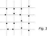
図3は、位置を決定するために装置によって読み込まれる4×4のマークを含む画像の一例を示している。
これらの4×4のマークは、次の値を持っている。
4 4 4 2
3 2 3 4
4 4 2 4
1 3 2 4
【0091】
これらの値は、次の2進XコードとYコードを表している。
Xコード: Yコード:
0 0 0 0 0 0 0 1
1 0 1 0 0 1 0 0
0 0 0 0 0 0 1 0
1 1 0 0 1 0 1 0
【0092】
Xコード内の垂直方向のビットの並びは、ビット列内の位置2 0 4 6を符号化している。縦列間の差は−2 4 2であり、7を法とする剰余は5 4 2になる。これは、混合基数で、(5−3)×8+(4−3)×2+(2−1)=16+2+1=19というコード・ウィンドウの位置番号を符号化している。最初に符号化されるコード・ウィンドウは位置0である。よって、1〜2の範囲内にあり、部分表面の4×4のマーク内に見られるこの差は、20番目の差になる。更に、このような差のそれぞれに対する全部で3つの縦列が存在し、開始の縦列が存在するので、4×4のXコードの一番右の縦方向の並びがXコードの61番目(縦列60)の縦列に属し(3×20+1=61)、一番左の縦方向の並びが58番目(縦列57)に属する。
【0093】
Yコードの水平方向のビットの並びは、数字列内の位置0 4 1 3を符号化する。これらの水平方向のビットの並びは、58番目の縦列から始まるので、横行の開始位置は、これらの数字から57を引いたものの7を法とする剰余であり、開始位置が6 3 0 2になる。混合基数の数に変換すると、これは6−2、3−2、0−0、2−2=4 1 00になる。ここで、3番目の桁が注目している数字内の最下位桁である。次に、4番目の桁が次の数字内の最上位桁である。この場合、これは、注目している数字内のものと同じにならなければならない(注目している数字が位置の全てで取り得る最大の数から構成される場合に、例外が発生する。その場合、次の数字の始まりが、注目している数字の始まりよりも1大きくなることが分かる)。
【0094】
位置番号は、混合基数で、0×50+4×10+1×2+0×1=42になる。
従って、Yコードの3番目の水平ビットの並びが、43番目のコード・ウィンドウに属し、これは0か1の開始位置を持ち、そして、このようなコード・ウィンドウのそれぞれについて全部で4行あるので、3番目の行が43×4=172番になる。
従って、この例で、4×4のマークを備える部分表面の一番左上の角の位置が(58,170)になる。
【0095】
4×4グループにおけるXコード内の垂直ビットの並びが横行170上で始まるので、全パターンのX縦列は、数字列の位置((2 0 4 6)−169) mod 7=1 6 3 5から始まる。最後の開始位置(5)と最初の開始位置の間で、数字0〜19が混合基数で符号化され、混合基数での数字0〜19の表記を合計することによって、これらの縦列の間の合計差を得る。これを行なう簡単なアルゴリズムがこれら20個の数字を生成し、直接それらの数を合計することになる。結果の総和をsと呼ぶことにすると、頁や書き込み面は、(5−s)mod7によって得られる。
【0096】
コード・ウィンドウを識別できるようにするために、部分表面においてどのビットが最下位のものであるかを決定する他の方法を、以下に説明する。最下位ビット(LSB)は、部分表面の差すなわち横行での位置番号における最小の数として定義される。このようにして、座標の最大使用可能な数の減少(冗長性)は、相対的に小さい。例えば、前述の例のX方向における初めの幾つかのコード・ウィンドウは、全て、LSB=1で、他の桁として2と6の間の数を持つことができ、これは25個のコード・ウィンドウとなり、次のコード・ウィンドウは、LSB=2、及び3と6の間の他の数を持つことができ、これは16個のコード・ウィンドウとなり、次のコード・ウィンドウは、LSB=3、及び4と6の間の他の数を持つことができ、これは9個のコード・ウィンドウとなり、次のコード・ウィンドウは、LSB=4、及び5と6の間の他の数を持つことができ、これは4個のコード・ウィンドウとなり、次のコード・ウィンドウは、LSB=5、及び6である他の数を持つことができ、これは1個のコード・ウィンドウとなり、総計で、前述の例の32個に対し、55個のコード・ウィンドウを持つ。
【0097】
上記の例で、一実施形態が説明され、その中で、各位置は4×4のマークを使用して符号化され、7ビットの数字列が使用された。もちろん、これは、ほんの一例にすぎない。位置は、より多くのまたはより少ない数のマークを使用して符号化できる。両方の方向で同じ数である必要がない。数字列を異なった長さにし、2進数以外にしても良いし、他の基数、例えば16進コードに基づくことも可能である。X方向の符号化とY方向の符号化に異なった数字列を使用可能である。マークは、異なる個数の値を表すことも可能である。
【0098】
実用的な例において、部分表面として、6×6のマークからなるものが使用され、この場合、ビット列は、最大26ビット、すなわち64ビットとすることができる。しかしながら、部分表面の回転位置を決定する能力を持たせるために、51ビットのビット列、すなわち51個の位置を使用する。このようなビット列の例は、以下のとおりである。
000001100011111010101101100110100010100111011110010
【0099】
このような6×6のマークからなる部分表面は、理論上、46*6個の位置を符号化でき、前述の0.3mmのラスター寸法では、巨大な表面となる。
【0100】
7ビット列を用いた前述のものと同様の方法で、本発明に従えば、前記特性は、部分表面を、少なくともその中央において、部分表面の両側の1ビットを含むように拡大して、6×6のシンボルの部分表面内の3番目及び4番目の行において、8個のマーク(部分表面の各側に1個ずつ)が読まれるようにし、これをY方向も同様とするという方法で利用できる。前述の51ビットを含むビット列は、6ビットのビット並びが、ただ1度だけ出現し、6ビットの前述のビット並びを含む8ビットの並びが、ただ1度だけ出現し、決して逆転した位置又は反転及び逆転されたときには出現しないという特性を有している。このようにして、部分表面の回転位置は、横行3、横行4、縦列3及び/又は縦列4における8ビットを読むことによって、決定できる。回転位置が分かれば、部分表面は、処理を続ける前に、正しい位置に回転することができる。
【0101】
できるだけランダムなパターンを得ることが望ましく、こうすれば、過度に対称的な領域は出現しない。6×6のマークを備える部分表面が、図2a〜2dに従った異なる位置の全てを有するマークを含むパターンを得ることが望ましい。更にばらつき度を増大し、繰り返しの特性を避けるために、「シャッフル」と呼ばれる方法が使用できる。各水平ビット並びは、所定の開始位置から始まる。しかしながら、ずれ量が分かっているのなら、各横行毎に、水平方向における開始位置をずらすことができる。これは、隣接する横行に対し、各最下位ビット(LSB)に別々のずれベクトルを割り当てることにより行うことができる。このずれベクトルは、各横行が水平方向にずらされる量を規定する。これは、見た目には図1のY軸が「スパイク状」であるかのように理解できる。
【0102】
4×4のコード・ウィンドウを用いた上述の例において、このずれベクトルは、LSB=0に対し、1,2,4,0とすることができ、LSB=1に対し、2,2,3,0とすることができる。これは、2と0をそれぞれ差し引いた後、処理を続ける前に、上述のずれ量がビット並びの位置番号から差し引かれる(5を法とする剰余で)こととなることを意味する。上述の例において、Y座標に関し、混合基数で数4 1 0 0(S2,S1,S0,S4)が得られ、ここで、右から2つめの数が最下位桁(LSB)である。ずれベクトル1,2,4,0が数字4と1に用いられるので(LSB=0)、2が4から引かれてS2=2となり、4が1から引かれて(5を法とする剰余で)S1=2となる。数字S0=0は変わらずに残る(最下位桁に対するずれベクトルの値は、常に0である)。最後に、数字S4は、次のコード・ウィンドウに属し、これはLSB=1であり、第2のずれベクトルが使用される。従って、2が0から差し引かれ(5を法とする剰余で)、S4=3となる。
【0103】
同様の方法が、Y座標のコードを変えるために使用できる。しかしながら、上述の例においては差0が使用されておらず、コードは既に相対的にランダムに分散されているので、X座標を変える必要性は小さい。
【0104】
上記の例で、マークをドットとしているが、もちろん、別の外観にすることもできる。例えば、マークは、仮想ラスター点から始まり、そこから特定の位置に伸びる線や楕円から構成できる。ドット以外の他のシンボル、たとえば、正方形、長方形、三角形、円、楕円とすることができ、また、塗り潰されたものでも、そうでないものでもよい。
【0105】
上記の例では、マークは、正方形の形の部分表面内で、位置の符号化に使用されている。部分表面は例えば、六角形などの別の形にすることも可能である。マークは、直交するラスターにおけるラスター線に沿って配置される必要はなく、他の方法、例えば60度などの他の角度のラスターにおけるラスター線に沿って、配置され得る。極座標系を使用してもよい。
【0106】
図5及び図6に示すように、三角形又は六角形の形をしたラスターを使用することもできる。例えば、図5に示すように、三角形のラスターでは、各マークを6つの異なる方向にずらすことができ、66*6の部分表面位置に相応するより膨大な容量を提供する。図6の六角形のラスター、蜂の巣状パターンでは、各マークは、ラスター線に沿って3つの異なる方向にずらすことができる。
【0107】
前述したように、マークは、必ずしもラスター線に沿ってずらされる必要はなく、他の方向にずらす、例えば、正方形ラスター・パターンが用いられるときには、それぞれを四分区間内に配置することができる。六角形ラスター・パターンにおいては、マークを4又はそれ以上の異なる方向、例えば、ラスター線に沿うものとラスター線に対し60度の角度にある線に沿うものとで6つの異なる方向にずらすことができる。
【0108】
位置コードを検出できるようにするには、仮想ラスターが決定されることが必要である。これは、方形ラスター・パターンにおいては、異なるマーク間の距離を調べることによって行うことができる。2つのマーク間の最も短い距離は、水平方向において値1と3又は垂直方向において値2と4を持つ2つの隣接したマークから導かれるはずなので、これらのマークは、2つのラスター点の間の1つのラスター線上にある。このようなマークの組みが検出された場合に、関連するラスター点(基準位置)が、ラスター点間の距離とラスター点からのマークのずれ量の知識を使用して決定され得る。1度、2つのラスター点の位置が決定されると、他のマークへの測定された距離を使用して、ラスター点間の距離の知識から、次のラスター点が決定できる。
【0109】
マークがラスター線に沿って50μmずれており、ラスター線間は300μm離れている場合、2つのマークの最小距離、例えば値1と3を持ったマークにおける距離は200μmになる。次に小さい距離は、例えば、値1と2を持ったマークの間であり、これは255μmとなる。従って、最小距離と次に小さい距離との間には、相対的に区別可能な差がある。他の斜め方向のものまでの差は、また大きいものである。しかしながら、ずれ量が50μmより大きくなる、例えば、75μm(1/4)以上である場合、升目の斜め方向のものが問題を引き起こし、マークが属する基準位置の決定が困難となり得る。ずれ量が50μm以下、例えば、おおよそ35μm(1/8)以下の場合、最小距離は230μmとなり、267μmである次の距離とで大きな差がない。この場合、光学読み取りに対する要求が増大する。
【0110】
マークは、それ自身のラスター点を覆うべきでなく、従って、ずれ量の2倍以上の直径(200%)を持つべきでない。しかしながら、これは厳密なものではなく、所定のオーバーラップ(例えば、240%)は許容できる。最初に、センサーの解像度及びパターンを生成するのに使用する印刷プロセスでの要求によって、この最小サイズが決定される。しかしながら、マークは、ゴミやセンサーのノイズによる問題を避けるために、実用上、ずれ量のおおよそ50%より小さな直径とすべきでない。
【0111】
位置決定のための装置の一実施形態が、図4に図示される。装置は、おおよそペンと同じ形をしたケース11を備える。ケースの一方の短辺には開口12がある。この短辺は、位置決定が行なわれる表面に接触するか、または、表面から近い距離に保持されるように意図されている。
【0112】
ケースは、光学部品、電子回路部品および電源を基本的に含んでいる。
光学部品は、画像化されることになる表面を照明する少なくとも1個の発光ダイオード13、及び、二次元画像を記録するCCDやCMOSセンサーなどの光感知エリアセンサー14を備える。必要であれば、装置は、ミラー及び/又はレンズ系などの光学系を備えてよい。発光ダイオードは、赤外線発光ダイオードとすることができ、センサーは赤外線光に反応するものとすることができる。
装置の電源は、ケースの独立した区画に取り付けられた電池15から供給される。
電子回路部品は、センサー14により記録された画像に基づいて位置を決定するための画像処理手段16、詳細には、センサーからの画像を読み、それらの画像に基づいて位置決定を実行するようプログラムされたプロセッサを備えたプロセッサ・ユニットを含んでいる。
【0113】
本実施形態において、装置は、また、ペン先17を備えており、これを用いて、位置決定が実行されることとなる表面上に、通常の顔料による書き込みをすることができる。ペン先17は、ユーザが使うかどうかを選択できるよう出没自在である。特定の用途において装置は、ペン先を全く必要としない。
【0114】
顔料による書き込みは、好ましくは、赤外光に対し透過のタイプのものであり、マークは、好ましくは、赤外光を吸収する。赤外光を発光する発光ダイオードと赤外光に反応するセンサーを用いることによって、パターンに対する前述した書き込みに干渉されることなく、パターンの検出ができるようになる。
【0115】
装置は、また、ボタン18を備え、これによって、装置は、起動され、制御される。また、装置は、装置から及び装置へ情報を、例えば、赤外線、無線波又は超音波などを使用して、無線伝送するためのトランシーバ19を有する。装置はまた、位置又は記録した情報を表示するためのディスプレイ20を備える。
【0116】
テキストを記録する装置が、出願人のスウェーデン特許第9604008−4号に説明されている。この装置は、適切な方法でプログラムすれば、位置決定のために使用できる。顔料による書き込みのために本装置が使用される場合には、ペン先を備える必要がある。
【0117】
装置は、異なる物理的なケースに分けることができ、第1のケースは、位置符号化パターンの画像を記録し、これらを第2のケース内に含まれる部品に転送するために必要な部品を含み、前記第2のケース内の部品において、記録された画像に基づいて位置決定が実行される。
【0118】
前述のように、位置決定は、画像内でマークの場所を決定し、これを復号化すると共に、これによって得られたコードから位置を決定するソフトウェアを備えているプロセッサによって、実行される。当業者であれば、前述の例に基づいて、位置符号化パターンの部分画像に基づいて位置決定を実行するソフトウェアを設計することができるであろう。
【0119】
更に、前述の記載に基づいて、当業者は、位置符号化パターンを印刷するためのソフトウェアを設計することができるであろう。
【0120】
前記実施形態において、パターンは、光学的に読み取り可能なものであり、従って、センサーは光学的なものである。前述したように、パターンは、光学的な要素以外の要素に基づくことができる。この場合、センサーは、もちろん、対象の要素を読むことができるタイプのものでなければならない。このような要素の例としては、化学的、聴覚的又は電磁的なマークがある。容量性又は誘導性マークを用いることもできる。
【0121】
前述の実施形態において、ラスターは直交グリッドであった。これはまた、他の形状、例えば、60度の角度を有する菱形グリッド、三角又は六角グリッドなどでもよい。
【0122】
ずれは、4方向より多いものも少ないものも使用でき、例えば、六角仮想ラスターに沿う3方向のずれが使用できる。直交ラスターにおいては、ラスターの再現を容易にするために、2つのずれのみを使用してもよい。しかしながら、4方向におけるずれが好ましく、また、6か8方向も、本発明の範囲に含むことができる。
【0123】
前記実施形態においては、利用できる最長の循環数字列は使用されていない。その結果として、各種の方法で使用可能な冗長度が得られている。この冗長度は、例えば、エラー訂正、失われた又は隠れたマークの置き換えなどを行うために使用できる。
【図面の簡単な説明】
【図1】 図1は、位置符号化パターンを備えた本製品の一実施形態を図示している。
【図2】 図2は、本発明の一実施形態におけるマークのデザイン及び配置の方法を図示している。
【図3】 図3は、位置を符号化するのに使用する4×4のシンボルの例を図示している。
【図4】 図4は、位置の決定に用いることができる装置を図示している。
【図5】 図5は、三角状ラスターを用いた位置符号化パターンを示している。
【図6】 図6は、六角状ラスターを用いた位置符号化パターンを示している。[0001]
TECHNICAL FIELD OF THE INVENTION
The invention relates to a method for providing a position code according to the preamble of claim 1. The invention also relates to a method for calculating a position according to the preamble of claim 18. The invention further relates to a computer program product, a device for position determination and a product with a position code.
[0002]
BACKGROUND OF THE INVENTION
In various situations, it is desirable to be able to determine the absolute position on the surface. One example is related to the digitization of figures. Another example relates to the case where an electronic version of handwritten information is required.
[0003]
U.S. Pat. No. 5,852,434 describes an apparatus for determining an absolute position. This deviceA writing surface, a detector and a processor are provided. The writing surface can determine XY coordinatesHas position coding patternThe detector isCan detect position coding pattern. ProcessordetectionIsThe position of the detector on the writing surface can be determined based on the position coding pattern.This device is a userInWhen information is written or plotted on the writing surface,At the same time,Handwritten and plotted information on computerEnterPowerPossible toTo.
[0004]
U.S. Pat. No. 5,852,434 gives three examples of position coding. The first example is a symbol, each of which consists of three concentric circles. The outermost circle represents the X coordinate, and the middle circle represents the Y coordinate. Further, the outer two circles are divided into 16 parts, and different numbers are shown depending on how they are filled. That is, each pair of coordinates X and Y is encoded with a complex symbol having a unique appearance.
[0005]
In the second example, the coordinates of each point on the writing surface are represented by a barcode, and the barcode for the X coordinate is disposed on the barcode for the Y coordinate.
[0006]
As a third example, it is described that the X coordinate and the Y coordinate can be encoded using a checkerboard pattern. However, the configuration of the checkerboard pattern and the conversion method to coordinates are not described.
[0007]
The known pattern has a problem that the pattern is composed of complicated symbols. Making the symbol smaller makes it more difficult to produce a patterned writing surface and increases the risk of mispositioning. On the other hand, when the symbol is enlarged, the position resolution is lowered.
[0008]
Furthermore, since the processor has to interpret complicated symbols, there is a problem that the processing of the detected position coding pattern becomes more complicated.
[0009]
In addition, in order to be able to determine the position, it is necessary to record at least one symbol completely, so that the detector used for recording the position coding pattern does not allow four symbols to be recorded simultaneously. must not. Accordingly, the ratio between the required sensor surface and the surface of the position-coding pattern defining one position is large.
[0010]
Annex A of WO 92/17859 is a patternHowConstitutionOrAnd positionHowDecryptionOrRelateddo it,The following example is disclosed.
[0011]
First, m of s = (0,0,1,0,1,1,1) and t = (0,1,1)Number sequenceStart with.To form a position coding pattern:patternFirst inColumns number sequenceSame asDo. AfterVerticalColumnTheFormationTo dotNumber sequenceRefer to tIn the sequenceFirstofIf the element is 0In,SecondThe column is sSame as sequence.Instead, in the t sequenceFirstofelementIs 1in the case ofInIsSecondThe column iss number sequence1 circulationInshiftWill be the same as the sequence. AfterVerticalColumn,tIn the sequenceElement valueTherefore,It is formed similarly. As a result, the following pattern is obtained.
[0012]
0 0 1 1
0 0 0 1
1 1 0 0
0 0 1 0
1 1 0 1
1 1 1 0
1 1 1 1
[0013]
here,Suppose that position detection of a partial surface indicated by the following subset in the pattern is performed.
1 0 0
0 1 0
1 0 1
[0014]
This subsetInFirstofThe column is (1, 0, 1).This partial sequenceIs, In the s number sequenceAppears in position 2.thisSubsetInCirculationTypicalShift,(1,1).thisportionNumber sequenceIs,tIn the sequenceAppears at position 1.thispatternInAccumulationWasShift,(0, 0, 1, 2)thisThe vertical position of the subset is 2 + 0 = 2. Therefore, on the partial surfaceInThe position of the subset is (1, 2).
By using this pattern, the above-mentioned problems when using complex symbols are avoided, and the area ratio between the required sensor surface and the surface of the position-coding pattern that defines the position is reduced.
[0015]
However, an interesting property of this type of position-coding pattern is that it encodes a large pattern at a number of unique positions, allowing position determination on the largest possible surface. In the above example, sNumeric sequenceLongTheDue to the vertical sizeLimited,Also,tThe length of the sequenceDue to the horizontal sizeRestrictionHas been. However,Number sequenceThe k-bit partNumber sequenceTheWhen removed,ThatportionNumber sequenceButJust in the sequenceAppears only in one positionThatBecause it must have characteristics,The length of these sequencesCannot be extended indefinitely. thisLikeIn, The length of the sequenceWhen stretched,portionThe length of the sequenceAlso has to be stretched, so that the partial surface to be recorded for positioning is enlarged.
[0016]
SUMMARY OF THE INVENTION
It is an object of the present invention to show a method for providing a position code that allows a very large number of positions to be encoded.
[0017]
This object is achieved in whole or in part by the method of claim 1, the method of
[0018]
According to a first aspect, the present invention relates more particularly to a method for providing a position code on a surface.To do.here,A position code encodes multiple positions in a first direction on the surfaceTo do.The method comprises the step of using a first cyclic digit string.TheThis circular digit string is a number of the first predetermined length in the number string.ColumnEachplaceHas the characteristic that is uniquely determinedis doing.The method also includes the first cyclic numeral sequence along the surface.Number markPrintingdo it, Using different rotations of the first cyclic numeral sequence so that a predetermined deviation occurs between adjacent numeral sequencesIncluding steps.
[0019]
This method uses the printingDoA step of dividing the surface into a plurality of first code windows in a first direction;Including that. here,Each code windowIsHaving at least three first circular digit sequences and having one digit sequence overlapping one digit sequence of the adjacent first code window. Further, the printing step is performed at the time of printing.Use rotation of the first circular digit stringdo it, Encoding the position of each first code window in the first direction by a shift between the first circular digit strings belonging to the code window.Including that.
[0020]
This is because the position code is divided into a plurality of code windows, and each of those positions is encoded by the magnitude of the deviation between the cyclic digit sequences to which the code window belongs.,Different from the prior art. The code windowMore than oneArranged so that there is no shift belonging to the code window.Therefore,The encoding in the first direction is, CirculationIt is not based on misalignment according to the ring number sequence, so this avoids the inherent limitations.
For practical purposes, the aforementioned deviation is the sequence of the corresponding numbers in the number sequence.ofCan be determined as the difference between.
Also,1 of a circular digit stringOneThis rotation can also be referred to as a cyclic shift transformation of a numeric string.Therefore,Different rotations start at different places in the string.
As will be explained later, printing a circular digit string does not have to be done in an obvious way using numbers,,Preferably, for example, printing using graphical symbols that can be easily recognized in image processing of position codesIsThe
[0021]
In a preferred embodiment, such rotation of the circular digit string is used such that at least some deviations are greater than one. As a result, compared to when a deviation of 1 is used,ThanmanyThe position can be encoded in the first direction.
[0022]
In a preferred embodimentThe secondSuch a rotation of a cyclic digit sequence of 1 is used so that each code window shift defines a position number in the mixed radix indicating the first code window in the first direction.TheAlso, the smallest digit shift,It is indicated by this position number.
This position number is for item nYes.n is “number of first circular digit sequences in the code window minus 1”.
[0023]
The indicator of the shift of the smallest digit in the position number isIt makes it possible to determine the position of the partial surface. The partial surface isAre the same size as the code windows, but theyIs not the same asIn the first directionLeavePartially overlaps with two code windowsIs.
[0024]
The smallest digit shift isVariousIn the wayTo expressbe able to. One method isSo that the shift of the smallest digit is smaller than the other shifts,Rotation of the first circular digit stringuseIncluding use. The other way isThe mostSo that small-digit shifts are in the first size range and other shifts are in the second size range., Rotate the first circular digit stringIncluding using. The first method allows encoding of many positions.
[0025]
In a preferred embodiment, the method further comprises the step of generating different types of position codes.Including.This is generated by starting the first cyclic digit sequence in the first direction (this is the cyclic digit sequence for which the first deviation is to be calculated) from different positions for different types. The
As a result, the maximum number of positions that can be coded becomes even larger. The number of possible types is the first circular digit stringThe numbers that make upofPiecesEqual to a number.
[0026]
In a preferred embodiment, the position code also encodes a plurality of positions in a second direction on the surface.To do.The method includes the step of using a second circular digit sequence for this purpose.Including.thisSecondThe cyclic numeral sequence has a characteristic that each position of the number sequence of the second predetermined length is uniquely determined in the numeral sequence. Also,This methodDuplicate the second cyclic number sequence along the surface.Number markStep to printIncluding.This different rotation of the second cyclic digit sequence is used so that the second cyclic digit sequence starts from a different starting position.The Also,The printing stepIsDividing the surface into a plurality of non-overlapping second code windows;Including.Each second code windowInA predetermined plurality of second cyclic numeral sequencesIs included.The printing step also encodes the rotation of the second cyclic digit sequence with the start position of the second cyclic digit sequence to which each position of the second code window in the second direction is associated. To useInclude.
[0027]
The second direction encoding is based on the same principle as the first direction encoding.Yes.That is, based on the use of a code window with associated advantages. However, here, the starting position for each second cyclic digit string is used instead of the deviation, and more positions are used.Can be encodedGive possibility. However,this is,Based on the known position in the first direction.
The second direction position encoding method can be used with a first direction position encoding method other than the method according to the present invention.
The position in the second direction can be encoded by a mixed radix position number and the starting position of the smallest digit can be indicated in the same way as the code window in the first direction, with corresponding advantages.
[0028]
In a preferred embodiment, the second cyclic digit sequence is identical to the first cyclic digit sequence.GoodIt is preferably a binary number. In relation to decryption, the corresponding sequence of numbersplaceThis is advantageous because it is sufficient to store the table. In addition, first and second code windowsIsThey can be the same size and overlap each other.
[0029]
A simple position code for a position in a Cartesian coordinate system is that a first cyclic digit sequence is printed in the column direction on the surface and a second cyclic digit sequence is on the surface.sideIt is obtained by printing in the line direction (or printing in the opposite direction). The numbers in the string aresideline/VerticalBy columnone timeOr continuouslyNumber markCan be printed.Therefore,The same rotation of the number sequence is the samesideline/VerticalUsed through the queue.
[0030]
In a preferred embodiment, the printing of the first and second circulating digit strings is a raster covering the surface.InRaster wireofAt each intersection between the first circulation numberColumnofNumberAnd the second cycle numberColumnofNumberAnd belong to each intersectionNumberIs graphically encoded with a mark on the surface at the intersection. The raster can be printed on the surface, but is preferably virtual.
[0031]
Therefore,Each intersection belongs to a position encoded with respect to the first directionNumberAnd belongs to the position encoded with respect to the second directionThere will be numbers. theseNumberCan be different when encoding, but can also be encoded by one common mark on the surface. This enables high resolution and high information density.
[0032]
This intersection can also be referred to as a raster point. In a preferred embodiment, the first and second circular digit sequencesNumbersThe various possible combinations of are encoded with different positions of the mark relative to the intersection.
[0033]
If both numbers are bit strings, four different possibleNumber(0,0; 1,0; 0,1; 1,1). These are encoded by four different positions of the mark. The different positions can be predetermined deviations from the intersection along four different raster lines extending from the intersection. The intersection can be considered as a reference position,IntersectionThe mark is shifted.
[0034]
The use of marks representing different values depending on their position has many advantages. otherExampleAll the marks can have the same appearance, which facilitates the placement of the position code on the surface.
Assigned to the intersectionNumberOf courseMark misalignmentIt can be represented graphically by other methods. Instead, four marks of different appearance, or eachNumberOne mark for can be used.
[0035]
The method described above can be implemented by a computer program, an ASIC (Application Specific Integrated Circuit), an FPGA (Field Programmable Gate Array) or other suitable method.
[0036]
Another object of the present invention is to provide a method for determining position, which is suitable for use with position codes of the type described above.
This object is achieved in whole or in part by the method of claim 18 and the computer program product of claim 30.
[0037]
According to a second aspect, the present invention provides, RankA method for calculating a position in a first direction for an arbitrary partial surface of a predetermined size on a surface provided with a positioning codeTo do.This position code is based on the first circular digit sequence with respect to the encoding of the position in the first direction.Yes.The first cyclic numeral sequence has a characteristic that each position of the first numeric sequence of the first predetermined length in the numeric string is uniquely determined, and the adjacent first cyclic sequence Number strings are shifted from each other by a predetermined shift amountIn addition,Duplicate on the surface with different rotationsNumber markPrintedTheSaid methodIs, A plurality of first number sequences from the position code on the partial surfacespecificAnd determining each position of the first number sequence in the first cyclic number sequence, and based on these positions, the adjacent first numbers including the first number sequence from the partial surface A step of determining a deviation between the cyclic numeral sequences of 1CompriseYes. The method is characterized by determining, from the deviation, a position in a first direction of a first code window at which the partial surfaces at least partially overlap.TheThe code window is one of a plurality of code windows in the first direction, each of which includes a predetermined plurality of first cyclic numeral strings and is adjacent to the first code window. One number string that overlaps one number string.
[0038]
This method is advantageous because it allows position determination on the surface with position codes that encode a very large number of positions.
This method can be realized by a computer program, ASIC, FPGA, or any other suitable method.
The method for determining the position can implement additional steps suitable for decoding different implementations of the position coding pattern, which is obtained as a result of the method for providing the position code described above.
In particular, the method for determining the position in the second direction on the surface can be implemented according to claim 23. The steps defined in claim 23 can also be used with methods other than those described above for determining the position in the first method.
[0039]
Another object of the invention is to provide an apparatus for position determination, which is suitable for use in decoding position coding patterns of the type described above.
This object is achieved by the device according to claim 31.
[0040]
According to a third aspect, the invention relates to a device for determining a position.To do. This deviceA sensor that generates an image on a partial surface of a surface with a position codeWhen,Image processing means configured to perform calculations based on a subset of the position codeTheThe subset of position codes represents the position of a partial surface in a partial surface image according to a method according to any one of claims 18-29.
[0041]
A further object of the present invention is to provide a product with position coding patterns, which allows for the coding of a very large number of positions.
This object is achieved by a product according to claim 34.
[0042]
According to a fourth aspect, the present invention provides an arbitrary partial surface of a predetermined size on the surface of a product with a position code.about, For products that allow position determination in the first directionTo do.This position code is based on the first cyclic digit string for the encoding of the position in the first direction.Yes. First circulationThe number sequence has a characteristic that each position of the first number sequence of the first predetermined length in the number sequence is uniquely determined, and the first circulation number sequence adjacent to each other at different rotations. On the surface so that they are offset from each other by a predetermined amount of deviation.Number markPrintedTheA plurality of first number sequences from the position code are identifiable on a partial surface to determine the position of each of the first number sequences in the first cyclic number sequenceTheA deviation between adjacent first cyclic numeral sequences including the first number sequence from the partial surface can be determined based on their positions. The product is characterized in that the position in the first direction of the first code window at which the partial surfaces at least partially overlap can be determined from this deviation.TheHere, the first code window is one of a plurality of code windows in the first direction, each of which includes a predetermined plurality of first cyclic numeral sequences and adjacent first codes. It has one numeric string that overlaps one numeric string in the window.
[0043]
The advantages of this product are clear from the above description. Give position codeHow toThe features described in connection with the method of determining the position are naturally applicable to this product as well.
[0044]
Hereinafter, the present invention will be described in detail according to embodiments with reference to the accompanying drawings.
[0045]
DESCRIPTION OF PREFERRED EMBODIMENTS
FIG. 1 shows a part of a product in the form of a sheet of paper 1 on which at least part of its surface 2 is provided with an optically readable position-
[0046]
The position-coding pattern is provided with marks 4 which are arranged in an orderly manner on the surface 2 so as to have an appearance as a “pattern”. The sheet of paper has an X coordinate axis and a Y coordinate axis. The position determination can be performed across the surface of the product. In other examples, the surface that allows positioning can besmallIt can be made up of parts.
[0047]
The pattern is, for example, the electronic information written or plotted on this surfacePortrayalCan be used to provide ElectronicPortrayalCan be provided while writing on the surface with a pen, which is made possible by continuously determining the position of the pen on the sheet of paper by reading the position-coding pattern.
[0048]
The position coding pattern comprises a virtual raster and a plurality of marks 4, which are invisible to the eye and cannot be detected directly by a device for determining the position on the surface, Each of the multiple marksplaceDepending on, it represents one of four values 1 to 4 described below. Here, for the sake of clarity, it should be pointed out that the position coding pattern of FIG. 1 is shown enlarged. MoreIs shown in an arrayPart of a sheet of paperIs only.
[0049]
The position coding pattern is arranged such that the position of the partial surface on the entire writing surface is uniquely determined by the mark on this partial surface. The first and second
[0050]
2a-d show the markdesignThe method and the arrangement method with respect to the reference position 6 are shown. The reference position 6 (which can also be called a raster point) is represented by the intersection of the raster lines 8. The
[0051]
In one embodiment, the distance between raster lines is 300 μm and the angle between raster lines is 90 degrees. Spacing between other raster linesIs also possibleFor example, to match a printer or scanner having a resolution of a multiple of 100 dpi, 254 μm is possible, which corresponds to a distance between points of 25.4 mm / 100 (ie, 254 μm). ing.
[0052]
The value of the mark thus depends on where the mark is located relative to the reference position. In the example of FIG. 2, four positions are possible, which are on each raster line extending from the reference position. The deviation from the reference position is the same for all values.
[0053]
Each
[0054]
In one embodiment, the mark is at a position shifted by 50 μm along the
[0055]
The shift does not have to be along the raster line, and the mark can be arranged in the divided quadrant. However, if the marks are shifted along the raster line, the distance between the marks is minimal.Has a valueAs described in detail below, there is an advantage that it can be used to reproduce a raster line.
[0056]
Each mark is composed of generally circular dots having a radius that is approximately the same as or slightly smaller than the amount of displacement. The radius can be 25% to 120% of the deviation. This radius is more than the amount of deviationMuch moreIf it is larger, it will be difficult to determine the raster line. If this radius is very small, higher resolution is required to record the mark.
[0057]
The mark does not have to be a circle or a rounded one.Any suitable shape such as square, triangle etc.Can be used.
[0058]
Each mark usually covers multiple pixels of the sensor chipIn one embodiment,The centroids of these pixels are recorded or calculated and used in subsequent processing. Therefore, the exact shape of the mark is not important. Therefore,A relatively simple printing process can be used provided that the center of gravity of the mark can be guaranteed to have the required amount of deviation.The
[0059]
In the following, the mark in FIG. 2a represents the value 1, the mark in FIG. 2b represents the value 2, the mark in FIG. 2c represents the
[0060]
Each mark thus represents one of four values from 1 to 4. This means that the position coding pattern can be divided into a first position code for the X coordinate and a second position code for the Y coordinate. This division is as follows.
[0061]
[Table 1]
Thus, eachMark'sThe value is converted to a first value for X code (bit in this case) and a second value for Y code (bit in this case). In this way, two completely independent bit patterns are obtained using the pattern. Conversely, two or more bit patternsIn combination, Graphically encoded by multiple marks according to FIG.One shareCan be a pattern.
[0063]
Each position is encoded by a plurality of marks. In this example, 4 × 4 marks are used to encode two-dimensional, ie, X and Y coordinate positions.
[0064]
The position code is composed of a numeric string of 1 and 0, and the bit string has a characteristic that the same 4-bit sequence appears only once in the numeric string. The bit string is circular, and the same characteristics apply when the end of the numeric string is combined with the beginning of the numeric string. Therefore, the sequence of 4 bits is always a position uniquely determined in the bit string.numberhave.
[0065]
If a bit string has the characteristics described above for a 4-bit sequence, the bit string can be up to 16 bits long. However, in this example, a 7-bit length bit string is used as follows.
"0001010"
[0066]
This bit string includes the following seven unique 4-bit sequences that encode position numbers within the string:
[0067]
[Table 2]
In X-coordinate encoding, bit strings are written sequentially in columns across the entire surface to be encoded, and left column K0Corresponds to zero (0) of the X coordinate. In one column, the bit string is therefore repeated several times in succession.
[0069]
Encoding is based on the difference between adjacent bit strings in adjacent columns, i.e., misalignment. The magnitude of the difference isAdjacent columns areIn bit stringWhich inPosition number (ie, a sequence of bits)Does it begin withIt depends on.
[0070]
Specifically, the first column KnA sequence of 4 bits in and thus encodedPosition number that can have 0-6 (one position number)And adjacent column Kn + 1A sequence of 4 more adjacent bits in the corresponding “height” inNumber (the other position number)Between,Difference modulo 7nIf you take the result(difference)IsAnywhere along the two columnsThat is,Which"height"By the way, was the difference created?Regardless, it will be the same. Thus, for all of the Y coordinates, using the difference between the position numbers for the two bit sequences in the two columnsIndependent and immutableCan be encoded.
[0071]
In this example, each position on the surface is encoded by a partial surface containing 4 × 4 marks, so there are four vertical bit sequences, and thus three differences each having the value 0-6. The,Can be used to encode the X coordinate.
[0072]
The pattern is divided into code windows F and each code window has the property that it consists of 4 × 4 marks. Thus, four horizontal bit sequences and four vertical bit sequences can be used, three differences can be generated in the X direction, and four positions can be obtained in the Y direction. These three differences and four positions encode the position of the partial surface in the X and Y directions. The windows adjacent in the X direction have a common column as shown in FIG. Therefore,the firstCode window F0,0Is the column K0, K1, K2, KThreeA sequence of bits from, andsideRow R0, R1, R2, RThreeContains a sequence of bits from. Since the difference is used in the X direction, the X direction and the Y directionComing diagonally toWindow, ie window F1,1Is the column KThree, KFour, KFive, K6FromsideRow RFour, RFive, R6, R7Contains a sequence of bits from. When considering only coding in the X direction, the code window can be thought of as extending indefinitely in the Y direction. Similarly, when considering only the encoding in the Y direction, the code window can be considered as extending indefinitely in the X direction. like thisYDirection andXIn the directionRespectivelyThe first and second code windows extending indefinitely cooperate with a code window of the type shown in FIG.0,0Configure.
[0073]
Each window has window coordinates F giving the position of the window in the X directionxAnd window coordinates F giving the position of the window in the Y directionyAnd have. Accordingly, the correspondence between windows and columns is as follows.
Ki = 3 Fx
Rj = 4 Fy
[0074]
The encoding is performed as follows:One of the differencesΔ0Always has the value 1 or 2, which is the least significant digit S of the number representing the position of the code window in the X direction.0And the difference between the other two1, Δ2Become values in the range 3-6, which are the two high-order digits S for the code window coordinates1, S2It is done to point to. Therefore, XFor coordinatesThe difference becomes zerothingIs not allowed because the code pattern becomes symmetric. In other words, the columns are encoded such that the difference is as follows:
(3-6); (3-6); (1-2); (3-6); (3-6); (1-2); (3-6); (3-6); (1 ~ 2);(3-6); (3-6);...
[0075]
Thus, each X coordinate has two differences Δ between 3 and 6.1, Δ2, Followed by one or two difference Δ0Is encoded by Minimum difference Δ0If you subtract 1 from 1 and subtract 3 from the other differences, you get 3 numbers S2, S1, S0This gives directly the code window position number in the X direction in mixed radix, from which the X coordinate can be determined directly, as in the example shown below. The code window position numbers are:
S2 × (4 × 2) + S1 × 2 + S0 × 1
[0076]
Using the principles described above, code windows 0, 1, 2,..., 31 can be encoded using code window position numbers consisting of three numbers represented by three differences. These differences are encoded using a bit pattern based on the number sequence described above. The bit pattern is finally encoded graphically using the marks of FIG.
[0077]
In many cases, when reading a partial surface consisting of 4x4 marks, in many cases the partial surface does not match one code window, so it is possible to obtain a complete position number that encodes the X coordinate. Although not possible, two adjacent code windows in the X direction are covered, so that two position number parts can be obtained. AndeachThe least significant digit S0Is always 1 or 2, so whichdigitKnows if the
Can be easily reconstructed.
[0078]
The Y coordinate is encoded according to almost the same principle as used for the X coordinate using the code window. Circular number sequence (the same number sequence used to encode X) across the surface encoding position,HorizontalNextlineInsideRepeatedly written. Just as with the X coordinate,TheyofsideRows are different in the numeric string.RuFrom positionI.e.Using different bit sequences,start. However, no difference is used for the Y coordinate.sideCoordinate the coordinates using a value based on the starting position of that digit string in the row. Once the X coordinate of the 4x4 mark is determined,ThatIncluded in Y code of 4x4 marksidelineabout,Starting position in the stringButYou can actually decide.
[0079]
In the Y code, the most significant digit S0Is determined by making this a single number with a value within a certain range. In this example, foursideIn linehomeOne of theNext to thisLine is the least significant column S in the code window0To indicate that it is related to the other threesideLine to other column S in the code window1, S2, SThreeTo start from any of positions 2-6 in the string. Therefore, the following value sequence exists in the Y direction.
(2-6); (2-6); (2-6); (0-1); (2-6); (2-6); (2-6); (0-1); (2 ~ 6);…
[0080]
Thus, each code window is encoded using three values between 2 and 6, followed by values between 0 and 1.
[0081]
Subtracting 0 from the small value and subtracting 2 from the other values will result in a position S in the Y direction in the mixed radix in the same way as in the X directionThree, S2, S1, S0From which the code window position number can be determined directly. That is,
SThree × (5 × 5 × 2) + S2 × (5 × 2) + S1 × 2 + S0 × 1
[0082]
Using the above method, 4 × 4 × 2 = 32 position numbers in the X direction can be encoded for the code window. Each code window comprises a bit sequence from three columns, which gives 3 × 32 = 96 columns, ie X coordinates. Further, with respect to the code window, 5 × 5 × 5 × 2 = 250 position numbers can be encoded in the Y direction. Each such position number has foursideHorizontal from rowNaWith a bit sequence, this gives 4 × 250 = 1000 rows, ie Y coordinates. In this way, a total of 96,000 coordinate positions can be encoded.
[0083]
However, since the encoding of X is based on the difference, the position where the first digit string starts in the first code window can be selected. Considering that this first number sequence starts at 7 different positions, 7 × 96000 = 672000 positions can be encoded. If the X and Y coordinates are determined,the firstColumn K0It is inFirstThe starting position of the numeric string can be calculated.FirstThe aforementioned seven different starting positions of the number sequence allow different pages or writing surfaces on the product to be encoded.
[0084]
Theoretically 4x4symbolPartial surfaces with (each with 4 values) are 44 * 4Can be encoded, which is 4,294,967,296.PiecesCorresponds to the position of There is a redundancy of over 6000 (4294967296/672000) to allow a floating determination in the position of the partial surface.
[0085]
Redundancy isSomeIncluded in the constraints on the magnitude of the difference, andSome,Only 7 bits out of 16 are used for position codeIncluded in that. However, this latterthingCan be used to determine the rotational position of the partial surface. When the next bit in the bit string is added to the 4-bit sequence, a 5-bit sequence is obtained. The fifth bit is obtained by reading the adjacent bit just outside the partial surface used. Such additional bits are usually readily available.
[0086]
The partial surface read by the sensor can be rotated at four different rotational positions, ie 0, 90, 180 or 270 degrees with respect to the code window. In these cases where the partial surface is rotating, the reading of the code, however, is either in the X or Y direction compared to the case where the read code is read at a rotation angle of 0 degrees. Or, both are reversed and reversed. here,There is a slightly different decoding of the mark value.UsedAnd it follows the table belowShall.
[0087]
[Table 3]
The aforementioned 5-bit sequence has the property that it appears in the 7-bit string only in the correct direction and in a form that is neither reversed nor inverted. This is clear from the fact that the bit string (0001010) contains only two “1” s. Thus, every 5-bit sequence must contain at least three zeros, which are reversedWhen you do (if it is flipped, also at that time), Become one of three things that can't happen. Thus, when a 5-bit sequence is found that does not have a position number in the bit string, it can be concluded that this partial surface is probably rotated, and the new position isInspectionIs done.
[0089]
To further explain the invention according to the present embodiment, next, based on the position code in the previous embodimentconcreteAn example is shown.
[0090]
3 determines the positionforAn example of an image including 4 × 4 marks read by the apparatus is shown.
These 4 × 4 marks have the following values:
4 4 4 2
3 2 3 4
4 4 2 4
1 3 2 4
[0091]
These values represent the following binary X code and Y code.
X code: Y code:
0 0 0 0 0 0 0 0 1
1 0 1 0 0 1 0 0
0 0 0 0 0 0 0 1 0
1 1 0 0 1 0 1 0
[0092]
The sequence of bits in the vertical direction in the X code encodes positions 2 0 4 6 in the bit string. The difference between the columns is −2 4 2 and the remainder modulo 7 is 5 4 2. This is the mixed radix, (5-3) × 8 + (4-3) × 2 + (2-1) = 16 + 2 + 1 = 19ThatEncode code window position numberHaveThe The first encoded code window is at position 0. Therefore, this difference which is within the range of 1 to 2 and is seen in the 4 × 4 mark on the partial surface is the 20th difference. In addition, there are a total of three columns for each of these differences, and there is a starting column, so the rightmost vertical sequence of 4 × 4 X codes is the 61st column (column 60). ) (3 × 20 + 1 = 61), and the leftmost column in the vertical direction belongs to the 58th column (column 57).
[0093]
The horizontal sequence of bits of the Y code encodes positions 0 4 1 3 in the numeric string. Since these horizontal bit sequences start at the 58th column,sideThe starting position of the line is a remainder modulo 7 after subtracting 57 from these numbers, and the starting position is 6 3 0 2. When converted to a mixed radix number, this is 6-2, 3-2, 0-0, 2-2 = 4 100. Here, the third digit is the lowest digit in the number of interest. Next, the fourth digit is the most significant digit in the next number. In this case this must be the same as in the number of interest (an exception occurs if the number of interest consists of the largest number that can be taken in all of the positions). The start of the next number is one greater than the start of the number being noticed).
[0094]
The position number isIn the mixed radix, 0 × 50 + 4 × 10 + 1 × 2 + 0 × 1 = 42.
Thus, the third horizontal bit sequence of the Y code belongs to the 43rd code window, which has a starting position of 0 or 1, and there are a total of 4 lines for each such code window. Therefore, the third row is 43 × 4 = 172.
Accordingly, in this example, the position of the upper left corner of the partial surface having the 4 × 4 mark is (58, 170).
[0095]
The sequence of vertical bits in the X code in a 4x4 groupsideSince it starts on line 170, the X column of all patterns starts at the position of the number string ((2 0 4 6) -169)
[0096]
In order to be able to identify the code window, another method for determining which bit is the least significant on the partial surface is described below. The least significant bit (LSB) is the difference in the partial surfaceIe position numberDefined as the smallest number in. In this way, the reduction in the maximum usable number of coordinates (redundancy) is relatively small. For example, in the X direction of the previous exampleThe first fewAll code windows are LSB = 1And as other digitsCan have a number between 2 and 6, which results in 25 code windows, the next code window can have LSB = 2, and other numbers between 3 and 6, This would be 16 code windows, the next code window could have LSB = 3, and other numbers between 4 and 6, which would be 9 code windows and the next code window The window can have LSB = 4 and other numbers between 5 and 6, which will be 4 code windows, the next code window will be LSB = 5 and 6 etc. This is one code window, which in total has 55 code windows, compared to 32 in the previous example.
[0097]
In the above example, an embodiment was described, in which each position was encoded using 4x4 marks and a 7-bit number string was used. Of course, this is just one example. The position can be encoded using a greater or lesser number of marks. It need not be the same number in both directions. The numbers can be of different lengths and can be other than binary numbers, or can be based on other radixes, eg hexadecimal codes. Different numbers can be used for encoding in the X direction and encoding in the Y direction. Mark isDifferent number of valuesRepresentingIs also possible.
[0098]
In a practical example, a 6 × 6 mark is used as the partial surface, and in this case, the bit string has a maximum of 26Bits, ie 64 bits. However, in order to have the ability to determine the rotational position of the partial surface, a 51 bit string, i.e. 51 positions, is used. An example of such a bit string is as follows.
000001100011111010101101100110100010100111011110010
[0099]
The partial surface consisting of such 6 × 6 marks is theoretically 46 * 6The individual positions can be encoded, and with the aforementioned 0.3 mm raster dimensions, the surface is huge.
[0100]
In a manner similar to that described above using a 7-bit sequence, according to the present invention, the characteristic is expanded to include 6 bits at least in the middle to include one bit on both sides of the partial surface. In the third and fourth rows in the partial surface of 6 symbols, 8 marks (on each side of the partial surfaceOne by one) Can be read and used in the same way in the Y direction. In the bit string including 51 bits, the 6-bit bit sequence appears only once, and the 8-bit sequence including the 6-bit bit sequence appears only once and is never reversed or It has the characteristic that it does not appear when reversed and reversed. In this way, the rotational position of the
[0101]
It is desirable to obtain a pattern that is as random as possible, so that overly symmetric areas do not appear. It is desirable to obtain a pattern in which the partial surface with 6 × 6 marks contains marks having all of the different positions according to FIGS. In order to further increase the degree of variation and avoid repetitive characteristics, a method called “shuffle” can be used. Each horizontal bit sequence starts from a predetermined starting position. However, if you know the amount of deviation,sideThe start position in the horizontal direction can be shifted for each row. this is,For adjacent rampage,Each least significant bit (LSB)SeparateSlipCan be done by assigning a vector. This gapvectorEachsideSpecifies the amount by which lines are shifted horizontally.This looksY axis in Fig. 1But"spikeCondition"OrlikeUnderstandable.
[0102]
In the example above using a 4x4 code window, this shiftvectorCan be 1, 2, 4, 0 for LSB = 0 and 2, 2, 3, 0 for LSB = 1. this is,2 and 0 respectivelyPresentThis means that after the subtraction, before the processing is continued, the above-described deviation amount is subtracted from the position number of the bit sequence (with a remainder modulo 5). In the above example, with respect to the Y coordinate,number4 1 0 0 (S2, S1, S0, SFour), Where the second from the rightnumberIs the least significant digit (LSB). Slipvector1, 2, 4, 0 are used for the numbers 4 and 1 (LSB = 0), 2 is subtracted from 4 and S2= 2 and 4 is subtracted from 1 (with modulo 5) S1= 2. Number S0= 0 remains unchanged (deviation from the least significant digitvectorThe value of is always 0). MostrearAnd the number SFourBelongs to the next code window, which is LSB = 1 and the second deviationvectorIs used. Thus 2 is subtracted from 0 (with a modulo 5) and SFour= 3.
[0103]
A similar method can be used to change the Y coordinate code. However, in the above example, the difference 0 is not used and the code is already relatively randomly distributed, so there is little need to change the X coordinate.
[0104]
In the above example, the mark is a dot, but of course anotherappearanceIt can also be. For example, a mark starts from a virtual raster point and from therespecificIt can consist of lines and ellipses that extend to the position. Symbols other than dots, for example, squares, rectangles, triangles, circles, ellipses, may be filled or not.
[0105]
In the above example, the marks are used for position encoding within a square shaped partial surface. The partial surface can also have another shape, such as a hexagon. The marks need not be placed along raster lines in orthogonal rasters, but may be placed in other ways, for example along raster lines in other angle rasters, such as 60 degrees. A polar coordinate system may be used.
[0106]
As shown in FIGS. 5 and 6, a raster having a triangular or hexagonal shape may be used. For example, as shown in FIG. 5, in a triangular raster, each mark can be shifted in six different directions,6 * 6It provides a much larger capacity corresponding to the partial surface position. In the hexagonal raster, honeycomb pattern of FIG. 6, each mark can be shifted in three different directions along the raster line.
[0107]
As described above, the marks are not necessarily shifted along the raster line, but are shifted in other directions. For example, when a square raster pattern is used, each mark can be arranged in the quadrant. In a hexagonal raster pattern, the marks can be shifted in 6 different directions, 4 or more different directions, eg along the raster line and along a line at an angle of 60 degrees to the raster line. it can.
[0108]
To be able to detect the position code, a virtual raster is determined.It is necessary to. This is for a square raster pattern:DifferentBy examining the distance between marksbe able to. The shortest distance between two marksIsDerived from two adjacent marks with
[0109]
The mark is shifted by 50 μm along the raster line.Between raster linesFor a distance of 300 μm, the minimum distance between the two marks, for example, the distance between the marks with
[0110]
The mark should not cover its own raster point and therefore should not have a diameter (200%) more than twice the amount of deviation. However, this is not exact and a given overlap (eg, 240%) is acceptable. Initially, this minimum size is determined by the resolution of the sensor and the demands on the printing process used to generate the pattern. However, in order to avoid problems caused by dust and sensor noise, the mark is practically about 50% of the deviation amount.SmallerShould not be the diameter.
[0111]
One embodiment of an apparatus for position determination is illustrated in FIG. The device comprises a
[0112]
The case basically includes optical components, electronic circuit components, and a power source.
The optical component is at least one illuminating the surface to be imaged.Light emissionLight from
The device is powered by a
The electronic circuit component determines the position based on the image recorded by the sensor 14.forThe image processing means 16, in particular, includes a processor unit with a processor programmed to read the images from the sensors and perform position determination based on those images.
[0113]
In this embodiment, the device is also provided with a
[0114]
The writing with the pigment is preferably of the type transmissive to infrared light, and the mark preferably absorbs infrared light. By using a light emitting diode that emits infrared light and a sensor that reacts to infrared light, the pattern can be detected without being interfered with the above-described writing on the pattern.
[0115]
The device also comprises a button 18, whereby the device is activated and controlled. The device also includes a
[0116]
A device for recording text is described in Applicant's Swedish Patent No. 9604008-4. This device can be used for position determination if programmed in an appropriate manner. If the device is used for writing with pigments, a nib must be provided.
[0117]
The device can be divided into different physical cases, the first case records the images of the position coding pattern and the parts necessary to transfer them to the parts contained in the second case. In addition, position determination is performed on the components in the second case based on the recorded image.
[0118]
As mentioned above, positioning is performed on the mark in the image.placeIs executed by a processor equipped with software that determines and decodes it, and determines the position from the resulting code. One skilled in the art will be able to design software that performs position determination based on partial images of the position-coding pattern based on the above example.
[0119]
Furthermore, based on the foregoing description, one of ordinary skill in the art will be able to design software for printing position-coded patterns.
[0120]
In the above embodiment, the pattern is optically readable and therefore the sensor is optical. As mentioned above, the pattern is opticalElementsOther thanelementCan be based on. In this case, the sensor, of course,elementMust be of a type that can be read. like thiselementExamples of such are chemical, auditory or electromagnetic marks. Capacitive or inductive marks can also be used.
[0121]
In the previous embodiment, the raster was an orthogonal grid. This may also be other shapes, such as a diamond grid with a 60 degree angle, a triangular or hexagonal grid, etc.
[0122]
Deviation is 4 directionsMore or less can be usedFor example, a deviation in three directions along the hexagonal virtual raster can be used. In the orthogonal raster, the rasterReproductionUse only two deviations to facilitateEvenGood. However, displacement in 4 directions is preferred and 6 or 8 directionsAlsoCan be included in the scope of the present invention.
[0123]
In the embodiment, the longest available cyclic numeral sequence is not used. As a result, in various waysUsable redundancy is obtained. This redundancy is, For example, error correction,LostOr replace hidden marksCan be used to do.
[Brief description of the drawings]
FIG. 1 illustrates one embodiment of the product with a position-coding pattern.
FIG. 2 is a diagram of a mark in an embodiment of the present invention.designAnd the arrangement method.
FIG. 3 illustrates an example of a 4 × 4 symbol used to encode a position.
FIG. 4 shows the positionDecisionThe apparatus which can be used for is shown in figure.
FIG. 5 shows a position coding pattern using a triangular raster.
FIG. 6 shows a position encoding pattern using a hexagonal raster.
Claims (13)
前記方法は、The method
複数の数字の並びで構成される循環数字列であって、前記循環数字列に含まれる所定長さの部分数字列の各々の前記循環数字列における場所が明確に決定されるという特性を有する前記循環数字列を用いることと、A cyclic numeral sequence composed of a sequence of a plurality of numbers, characterized in that the location in each of the cyclic digit strings of each partial numeric string of a predetermined length included in the cyclic numeral sequence is clearly determined Using a circular digit sequence;
前記循環数字列を構成する数字を表すマークを印刷することにより、前記表面上に、前記所定の座標軸と交差する方向に延びる前記循環数字列の少なくとも一部を、前記所定の座標軸に沿う方向に複数並べることと、By printing marks representing numbers constituting the circular numeral string, at least a part of the circular numeral string extending in a direction intersecting the predetermined coordinate axis is formed on the surface in a direction along the predetermined coordinate axis. Arranging several,
を含み、Including
一つの前記コード・ウィンドウには、前記所定の座標軸に沿う方向で隣り合う複数の前記循環数字列にそれぞれ含まれる複数の前記部分数字列が含まれており、各部分数字列の循環数字列における場所には、前記隣り合う循環数字列の間で差が設けられており、One code window includes a plurality of the partial numeral strings included in each of the plurality of circular numeral strings adjacent to each other in the direction along the predetermined coordinate axis. The location is provided with a difference between the adjacent circular digit strings,
前記表面上の所定の座標軸に沿う方向の前記コード・ウィンドウの位置は、前記差に基づいて符号化されており、前記位置コードによって符号化されるべき前記所定の座標軸に沿う方向の位置は、前記コード・ウィンドウの位置に基づいて符号化されていることを特徴とする方法。The position of the code window in the direction along the predetermined coordinate axis on the surface is encoded based on the difference, and the position in the direction along the predetermined coordinate axis to be encoded by the position code is: A method of encoding based on a position of the code window.
前記方法は、The method
複数の数字の並びで構成される第2の循環数字列であって、前記第2の循環数字列に含まれる所定長さの第2の部分数字列の各々の前記第2の循環数字列における場所が明確に決定されるという特性を有する前記第2の循環数字列を用いることと、In the second cyclic numeral sequence, each of the second partial numeral sequences of a predetermined length included in the second cyclic numeral sequence, which is a second cyclic numeral sequence composed of a plurality of numbers Using the second cyclic number sequence having the property that the location is clearly determined;
前記マークとして前記第2の循環数字列を構成する数字を表すことが可能なマークを用いることにより、前記マークの印刷によって、前記表面上に、前記所定の座標軸に沿う方向に延びる前記第2の循環数字列の少なくとも一部を、前記第2の座標軸に沿う方向に複数並べることと、By using a mark capable of representing a number constituting the second circulation number string as the mark, the second extending in the direction along the predetermined coordinate axis on the surface by printing the mark. Arranging at least a part of a cyclic numeral sequence in a direction along the second coordinate axis;
を含み、Including
一つの前記コード・ウィンドウには、前記第2の座標軸に沿う方向で隣り合う複数の前記第2の循環数字列にそれぞれ含まれる複数の前記第2の部分数字列が含まれており、各第2の部分数字列の前記第2の循環数字列における場所は、前記所定の座標軸に沿う方向の前記コード・ウィンドウの位置に応じて、前記第2の循環数字列が開始される場所からずらされており、One code window includes a plurality of second partial numeral sequences respectively included in the plurality of second cyclic numeral sequences adjacent to each other in the direction along the second coordinate axis. The location of the second partial digit string in the second cyclic digit sequence is shifted from the place where the second cyclic digit sequence is started according to the position of the code window in the direction along the predetermined coordinate axis. And
前記表面上の第2の座標軸に沿う方向の前記コード・ウィンドウの位置は、前記第2の循環数字列が開始される場所に基づいて符号化されており、前記位置コードによって符号化されるべき前記第2の座標軸に沿う方向の位置は、前記第2の座標軸に沿う方向の前記コード・ウィンドウの位置に基づいて符号化されている請求項1〜4の何れか1つに記載の方法。The position of the code window in the direction along the second coordinate axis on the surface is encoded based on where the second circular digit string starts and should be encoded by the position code The method according to claim 1, wherein the position in the direction along the second coordinate axis is encoded based on the position of the code window in the direction along the second coordinate axis.
前記交点からの前記マークのずれにより、前記循環数字列を構成する数字と前記第2の循環数字列を構成する数字が表されている請求項5に記載の方法。The method according to claim 5, wherein numbers constituting the cyclic numeral string and numerals constituting the second cyclic numeral string are represented by deviation of the mark from the intersection.
前記プログラムは、コンピュータに、The program is stored in a computer.
循環数字列を構成する数字を表すマークを印刷することにより、前記表面上に、前記所定の座標軸と交差する方向に延びる前記循環数字列の少なくとも一部を、前記所定の座標軸に沿う方向に複数並べる処理を実行させ、By printing marks representing numbers constituting a cyclic numeral sequence, at least a part of the cyclic numeral sequence extending in a direction intersecting the predetermined coordinate axis is printed on the surface in a direction along the predetermined coordinate axis. Execute the process of arranging,
前記循環数字列は、複数の数字の並びで構成され、前記循環数字列に含まれる所定長さの部分数字列の各々の前記循環数字列における場所が明確に決定されるという特性を有するものであり、The cyclic numeral sequence is composed of a sequence of a plurality of numbers, and has a characteristic that a place in each of the cyclic digit strings of a partial numeric string of a predetermined length included in the cyclic numeral sequence is clearly determined. Yes,
一つの前記コード・ウィンドウには、前記所定の座標軸に沿う方向で隣り合う複数の前記循環数字列にそれぞれ含まれる複数の前記部分数字列が含まれており、各部分数字列の循環数字列における場所には、前記隣り合う循環数字列の間で差が設けられており、One code window includes a plurality of the partial numeral strings included in each of the plurality of circular numeral strings adjacent to each other in the direction along the predetermined coordinate axis. The location is provided with a difference between the adjacent circular digit strings,
前記表面上の所定の座標軸に沿う方向の前記コード・ウィンドウの位置は、前記差に基づいて符号化されており、前記位置コードによって符号化されるべき前記所定の座標軸に沿う方向の位置は、前記コード・ウィンドウの位置に基づいて符号化されていることを特徴とするプログラム。The position of the code window in the direction along the predetermined coordinate axis on the surface is encoded based on the difference, and the position in the direction along the predetermined coordinate axis to be encoded by the position code is: A program encoded according to the position of the code window.
前記表面上には、循環数字列を構成する数字を表すマークを印刷することにより、前記所定の座標軸と交差する方向に延びる前記循環数字列の少なくとも一部が、前記所定の座標軸に沿う方向に複数並べられており、On the surface, by printing a mark representing a number constituting a cyclic numeral string, at least a part of the cyclic numeral string extending in a direction intersecting the predetermined coordinate axis is in a direction along the predetermined coordinate axis. There are several,
前記循環数字列は、複数の数字の並びで構成され、前記循環数字列に含まれる所定長さの部分数字列の各々の前記循環数字列における場所が明確に決定されるという特性を有するものであり、The cyclic numeral sequence is composed of a sequence of a plurality of numbers, and has a characteristic that a place in each of the cyclic digit strings of a partial numeric string of a predetermined length included in the cyclic numeral sequence is clearly determined. Yes,
一つの前記コード・ウィンドウには、前記所定の座標軸に沿う方向で隣り合う複数の前記循環数字列にそれぞれ含まれる複数の前記部分数字列が含まれており、各部分数字列の循環数字列における場所には、前記隣り合う循環数字列の間で差が設けられており、One code window includes a plurality of the partial numeral strings included in each of the plurality of circular numeral strings adjacent to each other in the direction along the predetermined coordinate axis. The location is provided with a difference between the adjacent circular digit strings,
前記所定の座標軸に沿う方向の前記コード・ウィンドウの位置は、前記差に基づいて符号化されており、前記位置コードによって符号化されるべき前記所定の座標軸に沿う方向の位置は、前記コード・ウィンドウの位置に基づいて符号化されていることを特徴とする製品。The position of the code window in the direction along the predetermined coordinate axis is encoded based on the difference, and the position in the direction along the predetermined coordinate axis to be encoded by the position code is the code A product that is encoded based on the position of the window.
前記位置コードは、前記表面上の所定の座標軸に沿う方向に並べられるコード・ウィンドウを用いて、前記所定の座標軸に沿う方向の位置を符号化するものであり、The position code encodes a position in a direction along the predetermined coordinate axis using a code window arranged in a direction along the predetermined coordinate axis on the surface,
前記表面上には、循環数字列を構成する数字を表すマークを印刷することにより、前記所定の座標軸と交差する方向に延びる前記循環数字列の少なくとも一部が、前記所定の座標軸に沿う方向に複数並べられており、On the surface, by printing a mark representing a number constituting a cyclic numeral string, at least a part of the cyclic numeral string extending in a direction intersecting the predetermined coordinate axis is in a direction along the predetermined coordinate axis. There are several,
前記循環数字列は、複数の数字の並びで構成され、前記循環数字列に含まれる所定長さの部分数字列の各々の前記循環数字列における場所が明確に決定されるという特性を有するものであり、The cyclic numeral sequence is composed of a sequence of a plurality of numbers, and has a characteristic that a place in each of the cyclic digit strings of a partial numeric string of a predetermined length included in the cyclic numeral sequence is clearly determined. Yes,
前記方法は、The method
前記部分表面に含まれる少なくとも一つの前記コード・ウィンドウを、前記所定の座標軸に沿う方向で特定することと、Identifying at least one of the code windows included in the partial surface in a direction along the predetermined coordinate axis;
前記少なくとも一つのコード・ウィンドウから、前記所定の座標軸に沿う方向で隣り合う複数の前記循環数字列にそれぞれ含まれる複数の前記部分数字列を特定することと、Identifying the plurality of partial numeral sequences respectively included in the plurality of cyclic numeral sequences adjacent in the direction along the predetermined coordinate axis from the at least one code window;
前記隣り合う循環数字列の間で、各部分数字列の循環数字列における場所に設けられた差を求めることと、Obtaining a difference provided in a place in the cyclic digit string of each partial digit string between the adjacent cyclic digit strings;
前記差に基づいて、前記表面上の所定の座標軸に沿う方向の前記コード・ウィンドウの位置を求めることと、Determining the position of the code window in a direction along a predetermined coordinate axis on the surface based on the difference;
前記所定の座標軸に沿う方向の前記コード・ウィンドウの位置に基づいて、前記位置コードによって符号化された前記所定の座標軸に沿う方向の位置を求めることと、Determining a position in the direction along the predetermined coordinate axis encoded by the position code based on the position of the code window in the direction along the predetermined coordinate axis;
を含むことを特徴とする方法。A method comprising the steps of:
前記マークとして第2の循環数字列を構成する数字を表すことが可能なマークを用いることにより、前記マークの印刷によって、前記表面上に、前記所定の座標軸に沿う方向に延びる前記第2の循環数字列の少なくとも一部が、前記第2の座標軸に沿う方向に複数並べられており、The second circulation extending in the direction along the predetermined coordinate axis on the surface by printing the mark by using a mark capable of representing a number constituting a second circulation numeral string as the mark. A plurality of numeric strings are arranged in a direction along the second coordinate axis,
前記第2の循環数字列は、複数の数字の並びで構成され、前記第2の循環数字列に含まれる所定長さの第2の部分数字列の各々の前記第2の循環数字列における場所が明確に決定されるという特性を有するものであり、The second cyclic numeral sequence is composed of an array of a plurality of numbers, and each second partial numeric string having a predetermined length included in the second cyclic numeral sequence is a place in the second cyclic numeral sequence. Has the characteristic that is clearly determined,
前記方法は、The method
前記部分表面に含まれる少なくとも一つの前記コード・ウィンドウを、前記第2の座標軸に沿う方向で特定することと、Identifying at least one of the code windows included in the partial surface in a direction along the second coordinate axis;
前記少なくとも一つのコード・ウィンドウから、前記第2の座標軸に沿う方向で隣り合う複数の前記第2の循環数字列にそれぞれ含まれる複数の前記第2の部分数字列を特定することと、Identifying the plurality of second partial numeral sequences respectively included in the plurality of second cyclic numeral sequences adjacent in the direction along the second coordinate axis from the at least one code window;
各第2の部分数字列の前記第2の循環数字列における場所が、前記所定の座標軸に沿う方向の前記コード・ウィンドウの位置に応じて、前記第2の循環数字列が開始される場所からずらされていることに基づいて、前記第2の循環数字列が開始される場所を求めることと、The location of each second partial digit sequence in the second cyclic digit sequence from the location where the second cyclic digit sequence is started according to the position of the code window in the direction along the predetermined coordinate axis. Determining where the second circular digit string starts based on being shifted;
前記第2の循環数字列が開始される場所に基づいて、前記表面上の第2の座標軸に沿う方向の前記コード・ウィンドウの位置を求めることと、Determining the position of the code window in a direction along a second coordinate axis on the surface based on where the second circular digit string begins;
前記第2の座標軸に沿う方向の前記コード・ウィンドウの位置に基づいて、前記位置コードによって符号化された前記第2の座標軸に沿う方向の位置を求めることと、Determining a position along the second coordinate axis encoded by the position code based on the position of the code window in the direction along the second coordinate axis;
を含む請求項9または10に記載の方法。The method according to claim 9 or 10, comprising:
前記位置コードは、前記表面上の所定の座標軸に沿う方向に並べられるコード・ウィンドウを用いて、前記所定の座標軸に沿う方向の位置を符号化するものであり、The position code encodes a position in a direction along the predetermined coordinate axis using a code window arranged in a direction along the predetermined coordinate axis on the surface,
前記表面上には、循環数字列を構成する数字を表すマークを印刷することにより、前記所定の座標軸と交差する方向に延びる前記循環数字列の少なくとも一部が、前記所定の座標軸に沿う方向に複数並べられており、On the surface, by printing a mark representing a number constituting a cyclic numeral string, at least a part of the cyclic numeral string extending in a direction intersecting the predetermined coordinate axis is in a direction along the predetermined coordinate axis. There are several,
前記循環数字列は、複数の数字の並びで構成され、前記循環数字列に含まれる所定長さの部分数字列の各々の前記循環数字列における場所が明確に決定されるという特性を有するものであり、The cyclic numeral sequence is composed of a sequence of a plurality of numbers, and has a characteristic that a place in each of the cyclic digit strings of a partial numeric string of a predetermined length included in the cyclic numeral sequence is clearly determined. Yes,
前記プログラムは、コンピュータに、The program is stored in a computer.
前記部分表面に含まれる少なくとも一つの前記コード・ウィンドウを特定する処理と、Identifying at least one code window included in the partial surface;
前記少なくとも一つのコード・ウィンドウから、前記所定の座標軸に沿う方向で隣り合う複数の前記循環数字列にそれぞれ含まれる複数の前記部分数字列を特定する処理と、A process of specifying a plurality of partial numeral sequences included in each of the plurality of cyclic numeral sequences adjacent in the direction along the predetermined coordinate axis from the at least one code window;
前記隣り合う循環数字列の間で、各部分数字列の循環数字列における場所に設けられた差を求める処理と、A process of obtaining a difference provided at a location in the cyclic digit string of each partial digit string between the adjacent cyclic digit strings;
前記差に基づいて、前記表面上の所定の座標軸に沿う方向の前記コード・ウィンドウの位置を求める処理と、A process for determining the position of the code window in a direction along a predetermined coordinate axis on the surface based on the difference;
前記所定の座標軸に沿う方向の前記コード・ウィンドウの位置に基づいて、前記位置コードによって符号化された前記所定の座標軸に沿う方向の位置を求める処理と、Processing for obtaining a position in the direction along the predetermined coordinate axis encoded by the position code based on the position of the code window in the direction along the predetermined coordinate axis;
を実行させることを特徴とするプログラム。A program characterized by having executed.
前記位置コードは、前記表面上の所定の座標軸に沿う方向に並べられるコード・ウィンドウを用いて、前記所定の座標軸に沿う方向の位置を符号化するものであり、The position code encodes a position in a direction along the predetermined coordinate axis using a code window arranged in a direction along the predetermined coordinate axis on the surface,
前記表面上には、循環数字列を構成する数字を表すマークを印刷することにより、前記所定の座標軸と交差する方向に延びる前記循環数字列の少なくとも一部が、前記所定の座標軸に沿う方向に複数並べられており、On the surface, by printing a mark representing a number constituting a cyclic numeral string, at least a part of the cyclic numeral string extending in a direction intersecting the predetermined coordinate axis is in a direction along the predetermined coordinate axis. There are several,
前記循環数字列は、複数の数字の並びで構成され、前記循環数字列に含まれる所定長さの部分数字列の各々の前記循環数字列における場所が明確に決定されるという特性を有するものであり、The cyclic numeral sequence is composed of a sequence of a plurality of numbers, and has a characteristic that a place in each of the cyclic digit strings of a partial numeric string of a predetermined length included in the cyclic numeral sequence is clearly determined. Yes,
前記装置は、The device is
前記部分表面に含まれる少なくとも一つの前記コード・ウィンドウを特定する手段と、Means for identifying at least one code window included in the partial surface;
前記少なくとも一つのコード・ウィンドウから、前記所定の座標軸に沿う方向で隣り合う複数の前記循環数字列にそれぞれ含まれる複数の前記部分数字列を特定する手段と、Means for identifying a plurality of partial numeral strings included in each of the plurality of circular numeral strings adjacent in a direction along the predetermined coordinate axis from the at least one code window;
前記隣り合う循環数字列の間で、各部分数字列の循環数字列における場所に設けられた差を求める手段と、Means for obtaining a difference provided at a place in the cyclic digit string of each partial numeric string between the adjacent cyclic digit strings;
前記差に基づいて、前記表面上の所定の座標軸に沿う方向の前記コード・ウィンドウの位置を求める手段と、Means for determining a position of the code window in a direction along a predetermined coordinate axis on the surface based on the difference;
前記所定の座標軸に沿う方向の前記コード・ウィンドウの位置に基づいて、前記位置コードによって符号化された前記所定の座標軸に沿う方向の位置を求める手段と、Means for determining a position in the direction along the predetermined coordinate axis encoded by the position code based on the position of the code window in the direction along the predetermined coordinate axis;
を備えることを特徴とする装置。A device comprising:
Applications Claiming Priority (3)
| Application Number | Priority Date | Filing Date | Title |
|---|---|---|---|
| SE9903541-2 | 1999-10-01 | ||
| SE9903541A SE517445C2 (en) | 1999-10-01 | 1999-10-01 | Position determination on a surface provided with a position coding pattern |
| PCT/SE2000/001897 WO2001026033A1 (en) | 1999-10-01 | 2000-10-02 | Position determination - calculation |
Publications (3)
| Publication Number | Publication Date |
|---|---|
| JP2003511762A JP2003511762A (en) | 2003-03-25 |
| JP2003511762A5 JP2003511762A5 (en) | 2011-05-06 |
| JP4746807B2 true JP4746807B2 (en) | 2011-08-10 |
Family
ID=20417215
Family Applications (16)
| Application Number | Title | Priority Date | Filing Date |
|---|---|---|---|
| JP2001528920A Withdrawn JP2003511763A (en) | 1999-10-01 | 2000-10-02 | Determining the position code |
| JP2001528918A Expired - Fee Related JP4658427B2 (en) | 1999-10-01 | 2000-10-02 | Encoded paper for optical reading |
| JP2001528919A Expired - Fee Related JP4746807B2 (en) | 1999-10-01 | 2000-10-02 | Position determination-calculation |
| JP2005374365A Expired - Fee Related JP3842283B2 (en) | 1999-10-01 | 2005-12-27 | Product for performing information processing using coding pattern and coding pattern generation method |
| JP2005374363A Expired - Fee Related JP3881365B2 (en) | 1999-10-01 | 2005-12-27 | Information processing apparatus using position coding pattern and method for generating position coding pattern |
| JP2005374364A Expired - Fee Related JP3872499B2 (en) | 1999-10-01 | 2005-12-27 | Information processing method using position coding pattern |
| JP2005374362A Expired - Fee Related JP3872498B2 (en) | 1999-10-01 | 2005-12-27 | Product and information processing method for information processing using position coding pattern |
| JP2008189559A Expired - Fee Related JP4778991B2 (en) | 1999-10-01 | 2008-07-23 | Encoded paper for optical reading |
| JP2010074743A Expired - Fee Related JP4613251B2 (en) | 1999-10-01 | 2010-03-29 | Encoded paper for optical reading |
| JP2010085605A Expired - Fee Related JP4769901B2 (en) | 1999-10-01 | 2010-04-02 | Encoded paper for optical reading |
| JP2010250155A Expired - Lifetime JP5235970B2 (en) | 1999-10-01 | 2010-11-08 | Encoded paper for optical reading |
| JP2012156046A Expired - Fee Related JP5734925B2 (en) | 1999-10-01 | 2012-07-12 | Encoded paper for optical reading |
| JP2013131240A Withdrawn JP2013219821A (en) | 1999-10-01 | 2013-06-24 | Coding sheet for optical reading |
| JP2013231633A Expired - Fee Related JP5779629B2 (en) | 1999-10-01 | 2013-11-08 | Encoded paper for optical reading |
| JP2015100611A Pending JP2015215902A (en) | 1999-10-01 | 2015-05-18 | Encoded paper for optical reading |
| JP2016188095A Pending JP2017037661A (en) | 1999-10-01 | 2016-09-27 | Encoded paper for optical reading |
Family Applications Before (2)
| Application Number | Title | Priority Date | Filing Date |
|---|---|---|---|
| JP2001528920A Withdrawn JP2003511763A (en) | 1999-10-01 | 2000-10-02 | Determining the position code |
| JP2001528918A Expired - Fee Related JP4658427B2 (en) | 1999-10-01 | 2000-10-02 | Encoded paper for optical reading |
Family Applications After (13)
| Application Number | Title | Priority Date | Filing Date |
|---|---|---|---|
| JP2005374365A Expired - Fee Related JP3842283B2 (en) | 1999-10-01 | 2005-12-27 | Product for performing information processing using coding pattern and coding pattern generation method |
| JP2005374363A Expired - Fee Related JP3881365B2 (en) | 1999-10-01 | 2005-12-27 | Information processing apparatus using position coding pattern and method for generating position coding pattern |
| JP2005374364A Expired - Fee Related JP3872499B2 (en) | 1999-10-01 | 2005-12-27 | Information processing method using position coding pattern |
| JP2005374362A Expired - Fee Related JP3872498B2 (en) | 1999-10-01 | 2005-12-27 | Product and information processing method for information processing using position coding pattern |
| JP2008189559A Expired - Fee Related JP4778991B2 (en) | 1999-10-01 | 2008-07-23 | Encoded paper for optical reading |
| JP2010074743A Expired - Fee Related JP4613251B2 (en) | 1999-10-01 | 2010-03-29 | Encoded paper for optical reading |
| JP2010085605A Expired - Fee Related JP4769901B2 (en) | 1999-10-01 | 2010-04-02 | Encoded paper for optical reading |
| JP2010250155A Expired - Lifetime JP5235970B2 (en) | 1999-10-01 | 2010-11-08 | Encoded paper for optical reading |
| JP2012156046A Expired - Fee Related JP5734925B2 (en) | 1999-10-01 | 2012-07-12 | Encoded paper for optical reading |
| JP2013131240A Withdrawn JP2013219821A (en) | 1999-10-01 | 2013-06-24 | Coding sheet for optical reading |
| JP2013231633A Expired - Fee Related JP5779629B2 (en) | 1999-10-01 | 2013-11-08 | Encoded paper for optical reading |
| JP2015100611A Pending JP2015215902A (en) | 1999-10-01 | 2015-05-18 | Encoded paper for optical reading |
| JP2016188095A Pending JP2017037661A (en) | 1999-10-01 | 2016-09-27 | Encoded paper for optical reading |
Country Status (15)
| Country | Link |
|---|---|
| US (9) | US6548768B1 (en) |
| EP (4) | EP1222605B1 (en) |
| JP (16) | JP2003511763A (en) |
| KR (6) | KR100906520B1 (en) |
| CN (5) | CN1326017C (en) |
| AT (3) | ATE410744T1 (en) |
| AU (3) | AU7977300A (en) |
| BR (2) | BR0014676B1 (en) |
| CA (3) | CA2384302A1 (en) |
| DE (3) | DE60044031D1 (en) |
| ES (1) | ES2341533T3 (en) |
| MX (2) | MXPA02003310A (en) |
| RU (3) | RU2261474C2 (en) |
| SE (1) | SE517445C2 (en) |
| WO (3) | WO2001026033A1 (en) |
Families Citing this family (408)
| Publication number | Priority date | Publication date | Assignee | Title |
|---|---|---|---|---|
| US7091959B1 (en) | 1999-03-31 | 2006-08-15 | Advanced Digital Systems, Inc. | System, computer program product, computing device, and associated methods for form identification and information manipulation |
| US6830196B1 (en) * | 1999-05-25 | 2004-12-14 | Silverbrook Research Pty Ltd | Identity-coded surface region |
| US6987573B1 (en) * | 1999-05-25 | 2006-01-17 | Silverbrook Research Pty Ltd | Interface surface printer |
| US7170499B1 (en) * | 1999-05-25 | 2007-01-30 | Silverbrook Research Pty Ltd | Handwritten text capture via interface surface |
| AU2003900983A0 (en) | 2003-03-04 | 2003-03-20 | Silverbrook Research Pty Ltd | Methods, systems and apparatus (NPT023) |
| AU2002952259A0 (en) | 2002-10-25 | 2002-11-07 | Silverbrook Research Pty Ltd | Methods and apparatus |
| AU7046700A (en) | 1999-08-30 | 2001-03-26 | Anoto Ab | Notepad |
| US7710408B2 (en) | 1999-08-30 | 2010-05-04 | Anoto Ab | Centralized information management based upon position information |
| EP1218815B1 (en) | 1999-09-17 | 2010-11-17 | Silverbrook Research Pty. Limited | Method and system for instruction of a computer |
| US7128270B2 (en) * | 1999-09-17 | 2006-10-31 | Silverbrook Research Pty Ltd | Scanning device for coded data |
| US7225979B2 (en) * | 1999-09-17 | 2007-06-05 | Silverbrook Research Pty Ltd | Methods and systems for object identification and interaction |
| US8136720B2 (en) * | 1999-09-17 | 2012-03-20 | Silverbrook Research Pty Ltd | Method of recording mail transactions |
| US7108192B2 (en) * | 1999-09-17 | 2006-09-19 | Silverbrook Research Pty Ltd | Rotationally symmetric tags |
| SE517445C2 (en) * | 1999-10-01 | 2002-06-04 | Anoto Ab | Position determination on a surface provided with a position coding pattern |
| US6993655B1 (en) * | 1999-12-20 | 2006-01-31 | Xerox Corporation | Record and related method for storing encoded information using overt code characteristics to identify covert code characteristics |
| SE9904746L (en) * | 1999-12-23 | 2001-06-24 | Anoto Ab | payment |
| US20030061188A1 (en) | 1999-12-23 | 2003-03-27 | Linus Wiebe | General information management system |
| US7295193B2 (en) | 1999-12-23 | 2007-11-13 | Anoto Ab | Written command |
| US6885878B1 (en) * | 2000-02-16 | 2005-04-26 | Telefonaktiebolaget L M Ericsson (Publ) | Method and system for using an electronic reading device as a general application input and navigation interface |
| US6832116B1 (en) | 2000-02-16 | 2004-12-14 | Telefonaktiebolaget L M Ericsson (Publ) | Method and system for controlling an electronic utility device using an electronic reading device |
| US6839623B1 (en) | 2000-02-16 | 2005-01-04 | Telefonaktiebolaget Lm Ericsson (Publ) | Positioning applications for an electronic reading device |
| US6813396B1 (en) | 2000-02-16 | 2004-11-02 | Telefonatiebolaget L.M. Ericsson (Publ) | Method for sharing information between electronic reading devices |
| US20010033293A1 (en) * | 2000-02-16 | 2001-10-25 | Magnus Hollstrom | Electronic pen help feedback and information retrieval |
| US6952497B1 (en) | 2000-02-16 | 2005-10-04 | Telefonaktiebolaget L M Ericsson (Publ) | Method and system for electronically recording transactions and performing security function |
| AU2001230255A1 (en) | 2000-02-16 | 2001-08-27 | Telefonaktiebolaget Lm Ericsson (Publ) | Printer pen |
| US6992655B2 (en) | 2000-02-18 | 2006-01-31 | Anoto Ab | Input unit arrangement |
| SE0000949L (en) | 2000-03-21 | 2001-09-22 | Anoto Ab | location information |
| US7254839B2 (en) | 2000-03-21 | 2007-08-07 | Anoto Ab | Secured access using a coordinate system |
| US6947033B2 (en) | 2000-03-21 | 2005-09-20 | Anoto Ab | Method and system for digitizing freehand graphics with user-selected properties |
| US7143952B2 (en) | 2000-03-21 | 2006-12-05 | Anoto Ab | Apparatus and methods relating to image coding |
| US7415501B2 (en) | 2000-03-21 | 2008-08-19 | Anoto Ab | Online graphical message service |
| US8418052B2 (en) | 2000-03-21 | 2013-04-09 | Anoto Aktiebolag (Anoto Ab) | Processing of documents |
| US6864880B2 (en) | 2000-03-21 | 2005-03-08 | Anoto Ab | Device and method for communication |
| US7072529B2 (en) | 2000-03-21 | 2006-07-04 | Anoto Ab | Systems and methods for information storage |
| US20060082557A1 (en) * | 2000-04-05 | 2006-04-20 | Anoto Ip Lic Hb | Combined detection of position-coding pattern and bar codes |
| AU2001246996A1 (en) | 2000-04-05 | 2001-10-15 | Anoto Ab | Method and system for information association |
| US6586688B2 (en) | 2000-04-05 | 2003-07-01 | Anoto Ab | Information-related devices and methods |
| US7050653B2 (en) | 2000-04-05 | 2006-05-23 | Anoto Ab | Identification of virtual raster pattern |
| US7094977B2 (en) | 2000-04-05 | 2006-08-22 | Anoto Ip Lic Handelsbolag | Method and system for information association |
| US7278017B2 (en) | 2000-06-07 | 2007-10-02 | Anoto Ab | Method and device for secure wireless transmission of information |
| JP4317334B2 (en) * | 2000-09-08 | 2009-08-19 | 株式会社リコー | Image forming apparatus and document management system |
| US6958747B2 (en) | 2000-08-30 | 2005-10-25 | Anoto Ab | Method for making a product |
| US6698660B2 (en) | 2000-09-07 | 2004-03-02 | Anoto Ab | Electronic recording and communication of information |
| US6722574B2 (en) | 2000-09-07 | 2004-04-20 | Anoto Ab | Business card |
| JP4776832B2 (en) * | 2000-10-19 | 2011-09-21 | キヤノン株式会社 | Coordinate input device and coordinate plate of image input device |
| US7127682B2 (en) | 2000-11-10 | 2006-10-24 | Anoto Ab | Device and system for information management utilizing a filing appliance |
| US7167164B2 (en) | 2000-11-10 | 2007-01-23 | Anoto Ab | Recording and communication of handwritten information |
| US7002559B2 (en) * | 2000-11-13 | 2006-02-21 | Anoto Ab | Method, system and product for information management |
| US7333947B2 (en) | 2000-11-13 | 2008-02-19 | Anoto Ab | Network-based system |
| US6798907B1 (en) | 2001-01-24 | 2004-09-28 | Advanced Digital Systems, Inc. | System, computer software product and method for transmitting and processing handwritten data |
| US20020107885A1 (en) * | 2001-02-01 | 2002-08-08 | Advanced Digital Systems, Inc. | System, computer program product, and method for capturing and processing form data |
| US7649637B2 (en) | 2001-04-05 | 2010-01-19 | Anoto Ab | Method for printing a global position-coding pattern |
| SE519012C2 (en) * | 2001-04-05 | 2002-12-23 | Anoto Ab | Ways to handle information |
| US6878062B2 (en) | 2001-04-06 | 2005-04-12 | Anoto Ab | Method for performing games |
| WO2002093467A1 (en) | 2001-05-11 | 2002-11-21 | Anoto Ab | Electronic pen with actuation through removal of cap |
| US7916124B1 (en) | 2001-06-20 | 2011-03-29 | Leapfrog Enterprises, Inc. | Interactive apparatus using print media |
| SE0102210L (en) | 2001-06-21 | 2003-02-12 | Anoto Ab | Program control procedure |
| SE0102236L (en) * | 2001-06-25 | 2002-12-26 | Anoto Ab | Control of a processor equipped unit |
| SE519277C2 (en) * | 2001-06-25 | 2003-02-11 | Anoto Ab | Device and method for position coding and for decoding a position code |
| US6667695B2 (en) | 2001-06-25 | 2003-12-23 | Anoto Ab | Position code |
| US7202861B2 (en) | 2001-06-25 | 2007-04-10 | Anoto Ab | Control of a unit provided with a processor |
| US6966495B2 (en) | 2001-06-26 | 2005-11-22 | Anoto Ab | Devices method and computer program for position determination |
| SE523700C2 (en) | 2001-06-26 | 2004-05-11 | Anoto Ab | Method, device and memory medium for position determination |
| US6732927B2 (en) | 2001-06-26 | 2004-05-11 | Anoto Ab | Method and device for data decoding |
| US7180509B2 (en) | 2001-06-26 | 2007-02-20 | Anoto Ab | Electronic pen, mounting part therefor and method of making the pen |
| SE0102253L (en) * | 2001-06-26 | 2002-12-27 | Anoto Ab | DATA PEN |
| US7110604B2 (en) | 2001-06-26 | 2006-09-19 | Anoto Ab | Processing of digital images |
| US20030016212A1 (en) * | 2001-06-27 | 2003-01-23 | Stefan Lynggaard | Method, computer program product and device for wireless connection |
| US7202963B2 (en) | 2001-06-28 | 2007-04-10 | Anoto Ab | Method for processing information |
| SE523112C2 (en) * | 2001-07-05 | 2004-03-30 | Anoto Ab | Procedures for communication between a user device that has the ability to read information from a surface, and servers that execute services that support the user device |
| US6727896B2 (en) * | 2001-08-01 | 2004-04-27 | Microsoft Corporation | Correction of alignment and linearity errors in a stylus input system |
| US7296075B2 (en) | 2001-08-23 | 2007-11-13 | Anoto Ab | Method, apparatus and system for connecting a portable unit to a particular server unit from among a plurality of server units |
| EP1435034A1 (en) | 2001-09-10 | 2004-07-07 | Anoto AB | Method, computer program product and device for arranging coordinate areas relative to each other |
| US7175095B2 (en) | 2001-09-13 | 2007-02-13 | Anoto Ab | Coding pattern |
| SE520045C2 (en) * | 2001-09-13 | 2003-05-13 | Anoto Ab | Coding Patterns |
| US7120320B2 (en) | 2001-09-21 | 2006-10-10 | Anoto Ab | Method and apparatus for displaying a handwritten message based on position and time data |
| US7457476B2 (en) | 2001-10-03 | 2008-11-25 | Anoto Ab | Optical sensor device and a method of controlling its exposure time |
| US7145556B2 (en) * | 2001-10-29 | 2006-12-05 | Anoto Ab | Method and device for decoding a position-coding pattern |
| SE0103589L (en) * | 2001-10-29 | 2003-04-30 | Anoto Ab | Method and apparatus for decoding a position coding pattern |
| US7321692B2 (en) | 2001-11-13 | 2008-01-22 | Anoto Ab | Method, device and computer program product for processing information in a memory |
| US7283676B2 (en) | 2001-11-20 | 2007-10-16 | Anoto Ab | Method and device for identifying objects in digital images |
| US7385595B2 (en) * | 2001-11-30 | 2008-06-10 | Anoto Ab | Electronic pen and method for recording of handwritten information |
| SE520682C2 (en) | 2001-12-06 | 2003-08-12 | Anoto Ab | Reconstruction of a virtual screen |
| US7356012B2 (en) | 2001-12-27 | 2008-04-08 | Anoto Ab | Method for transmitting information |
| US7162087B2 (en) | 2001-12-28 | 2007-01-09 | Anoto Ab | Method and apparatus for recording of electronic handwriting |
| TWI235926B (en) | 2002-01-11 | 2005-07-11 | Sonix Technology Co Ltd | A method for producing indicators and processing system, coordinate positioning system and electronic book system utilizing the indicators |
| SE0200419L (en) * | 2002-02-12 | 2003-08-13 | Anoto Ab | Electronic pen and sensor arrangement and control device for such |
| EP1476309B1 (en) | 2002-02-22 | 2009-12-30 | Print-Rite Unicorn Image Products Co. Ltd of Zhuhai | An intelligent ink cartridge and method for manufacturing the same |
| SE0201297D0 (en) * | 2002-04-30 | 2002-04-30 | Anoto Ab | Information management system and a method at said system |
| DE60331914D1 (en) | 2002-06-05 | 2010-05-12 | Anoto Ab | METHOD FOR MANAGING INFORMATION |
| DE60325064D1 (en) | 2002-06-18 | 2009-01-15 | Anoto Ab | POSITION CODING PATTERN |
| US6915281B2 (en) * | 2002-06-30 | 2005-07-05 | Pitney Bowes Inc. | Systems and methods using a digital pen for funds accounting devices and postage meters |
| RU2349956C2 (en) * | 2002-09-26 | 2009-03-20 | Кендзи ЙОСИДА | Method of information playback, method of information input/output, device for information playback, portable device of information input/output and electronic toy in with dot raster |
| CN102982298B (en) * | 2002-09-26 | 2016-12-07 | Ip解决方案株式会社 | Follow the tracks of device, information input/output unit, optical pickup device and information recording/playing back device |
| AU2015243058B2 (en) * | 2002-09-26 | 2018-03-22 | Kenji Yoshida | Information reproduction i/o method using dot pattern, information reproduction device, mobile information i/o device, and electronic toy |
| US7082444B2 (en) | 2002-09-30 | 2006-07-25 | Pitney Bowes Inc. | Method and system for identifying a form version |
| US7417773B2 (en) * | 2002-09-30 | 2008-08-26 | Pitney Bowes Inc. | Method and system for creating and sending a facsimile using a digital pen |
| US7343042B2 (en) * | 2002-09-30 | 2008-03-11 | Pitney Bowes Inc. | Method and system for identifying a paper form using a digital pen |
| US7167586B2 (en) * | 2002-09-30 | 2007-01-23 | Pitney Bowes Inc. | Method and system for remote form completion |
| EP1410916A1 (en) | 2002-10-18 | 2004-04-21 | Hewlett-Packard Company | Hybrid printing/pointing device |
| SE523931C2 (en) * | 2002-10-24 | 2004-06-01 | Anoto Ab | Information processing system arrangement for printing on demand of position-coded base, allows application of graphic information and position data assigned for graphical object, to substrate for forming position-coded base |
| EP1413974A1 (en) | 2002-10-24 | 2004-04-28 | Hewlett-Packard Company | Hybrid sensing techniques for position determination |
| WO2004038650A1 (en) * | 2002-10-25 | 2004-05-06 | Silverbrook Research Pty Ltd | Orientation-indicating cyclic position codes |
| US7133563B2 (en) * | 2002-10-31 | 2006-11-07 | Microsoft Corporation | Passive embedded interaction code |
| US7116840B2 (en) * | 2002-10-31 | 2006-10-03 | Microsoft Corporation | Decoding and error correction in 2-D arrays |
| US7009594B2 (en) * | 2002-10-31 | 2006-03-07 | Microsoft Corporation | Universal computing device |
| CA2508126C (en) | 2002-12-03 | 2010-02-23 | Silverbrook Research Pty Ltd | Rotationally symmetric tags |
| SE0203853D0 (en) | 2002-12-23 | 2002-12-23 | Anoto Ab | Data code |
| US7840492B2 (en) * | 2002-12-30 | 2010-11-23 | Pitney Bowes Inc. | Personal funds metering system and method |
| US7110576B2 (en) * | 2002-12-30 | 2006-09-19 | Pitney Bowes Inc. | System and method for authenticating a mailpiece sender |
| AU2004217403B2 (en) * | 2003-03-04 | 2007-07-26 | Silverbrook Research Pty Ltd | Symmetric tags |
| US7188769B2 (en) * | 2003-04-07 | 2007-03-13 | Silverbrook Research Pty Ltd | Laser scanner using rotating holographic optical element |
| US7991432B2 (en) * | 2003-04-07 | 2011-08-02 | Silverbrook Research Pty Ltd | Method of printing a voucher based on geographical location |
| WO2004097723A1 (en) | 2003-04-29 | 2004-11-11 | Anoto Ip Lic Hb | Methods, apparatus, computer program and storage medium for position decoding |
| EP1631898A1 (en) | 2003-05-26 | 2006-03-08 | Anoto IP Lic HB | Method for compressinga digital representation containing a page-describing code, which is sent from a computer to a printer |
| SE0301729D0 (en) * | 2003-06-13 | 2003-06-13 | Anoto Ab | Need-controlled printing of coding patterns |
| EP1656633B1 (en) * | 2003-06-13 | 2016-05-04 | Anoto AB | On-demand printing of coding patterns |
| FR2856473B1 (en) * | 2003-06-23 | 2005-12-09 | Groupe Silicomp | NAVIGATION METHOD, DEVICE, SYSTEM AND CORRESPONDING COMPUTER PROGRAMS |
| US7167166B1 (en) | 2003-08-01 | 2007-01-23 | Accenture Global Services Gmbh | Method and system for processing observation charts |
| US20050052706A1 (en) * | 2003-09-10 | 2005-03-10 | Nelson Terry M. | Location patterns and methods and apparatus for generating such patterns |
| US20050052700A1 (en) * | 2003-09-10 | 2005-03-10 | Andrew Mackenzie | Printing digital documents |
| GB0321173D0 (en) * | 2003-09-10 | 2003-10-08 | Hewlett Packard Development Co | Replying to e-mails,creating and sending e-mails,and apparatus, methods and software relating to such activities |
| GB0321164D0 (en) | 2003-09-10 | 2003-10-08 | Hewlett Packard Development Co | Methods,apparatus and software for printing location pattern |
| GB0321168D0 (en) * | 2003-09-10 | 2003-10-08 | Hewlett Packard Development Co | Printing of documents with position identification pattern |
| US20050052707A1 (en) * | 2003-09-10 | 2005-03-10 | Nelson Terry M. | Location patterns and methods and apparatus for generating such patterns |
| US6962450B2 (en) | 2003-09-10 | 2005-11-08 | Hewlett-Packard Development Company L.P. | Methods and apparatus for generating images |
| US20050060644A1 (en) * | 2003-09-15 | 2005-03-17 | Patterson John Douglas | Real time variable digital paper |
| US20050087610A1 (en) * | 2003-10-27 | 2005-04-28 | Adams Guy De W.B. | Visually significant marking in position encoded glyph carpets |
| SE0302884D0 (en) * | 2003-10-31 | 2003-10-31 | Anoto Ab | Information management unit and method for controlling data flow from electronic pens |
| JP3635374B1 (en) * | 2003-11-14 | 2005-04-06 | 有限会社Sires | Digital information carrier |
| SE0303058D0 (en) | 2003-11-18 | 2003-11-18 | Anoto Ab | Methods and arrangements in an information management system |
| JP4583382B2 (en) * | 2003-12-15 | 2010-11-17 | アノト アクティエボラーク | Optical system, analysis system and modular unit for electronic pens |
| SE0303370D0 (en) | 2003-12-16 | 2003-12-16 | Anoto Ab | Method, apparatus, computer program and storage medium for recording a movement of a user unit |
| US7111230B2 (en) * | 2003-12-22 | 2006-09-19 | Pitney Bowes Inc. | System and method for annotating documents |
| AU2003292817A1 (en) * | 2003-12-25 | 2005-07-21 | Kenji Yoshida | Method for inputting/outputting information using dot pattern |
| US7583842B2 (en) * | 2004-01-06 | 2009-09-01 | Microsoft Corporation | Enhanced approach of m-array decoding and error correction |
| US7463774B2 (en) * | 2004-01-07 | 2008-12-09 | Microsoft Corporation | Global localization by fast image matching |
| US7263224B2 (en) * | 2004-01-16 | 2007-08-28 | Microsoft Corporation | Strokes localization by m-array decoding and fast image matching |
| EP1569140A3 (en) | 2004-01-30 | 2006-10-25 | Hewlett-Packard Development Company, L.P. | Apparatus, methods and software for associating electronic and physical documents |
| GB2410590B (en) | 2004-01-30 | 2007-02-14 | Hewlett Packard Development Co | Physical object with memory tag and apparatus for use with such objects |
| GB0402022D0 (en) | 2004-01-30 | 2004-03-03 | Hewlett Packard Development Co | Method of obtaining at least a portion ofa document |
| SE0400322D0 (en) * | 2004-02-13 | 2004-02-13 | Anoto Ab | On-demand printing or coding patterns |
| US20050271961A1 (en) * | 2004-03-05 | 2005-12-08 | Jadwin Thomas A | Substrate and near infrared absorbing toner |
| US7831933B2 (en) | 2004-03-17 | 2010-11-09 | Leapfrog Enterprises, Inc. | Method and system for implementing a user interface for a device employing written graphical elements |
| US7453447B2 (en) | 2004-03-17 | 2008-11-18 | Leapfrog Enterprises, Inc. | Interactive apparatus with recording and playback capability usable with encoded writing medium |
| US20060125805A1 (en) * | 2004-03-17 | 2006-06-15 | James Marggraff | Method and system for conducting a transaction using recognized text |
| US7853193B2 (en) | 2004-03-17 | 2010-12-14 | Leapfrog Enterprises, Inc. | Method and device for audibly instructing a user to interact with a function |
| US20060067576A1 (en) | 2004-03-17 | 2006-03-30 | James Marggraff | Providing a user interface having interactive elements on a writable surface |
| US7242466B2 (en) * | 2004-03-31 | 2007-07-10 | Microsoft Corporation | Remote pointing system, device, and methods for identifying absolute position and relative movement on an encoded surface by remote optical method |
| US8054495B2 (en) | 2004-04-07 | 2011-11-08 | Hewlett-Packard Development Company, L.P. | Digital documents, apparatus, methods and software relating to associating an identity of paper printed with digital pattern with equivalent digital documents |
| US7048198B2 (en) * | 2004-04-22 | 2006-05-23 | Microsoft Corporation | Coded pattern for an optical device and a prepared surface |
| GB2413677A (en) * | 2004-04-28 | 2005-11-02 | Hewlett Packard Development Co | Digital pen and paper system using a pattern which encodes communication parameters |
| US7270277B1 (en) | 2004-05-21 | 2007-09-18 | Koziol Jeffrey E | Data encoding mark for placement in a compact area and an object carrying the data encoding mark |
| US7751585B2 (en) * | 2004-06-28 | 2010-07-06 | Microsoft Corporation | System and method for encoding high density geometric symbol set |
| SE0401647D0 (en) * | 2004-06-28 | 2004-06-28 | Anoto Ab | Coding and decoding of data |
| JP4996461B2 (en) * | 2004-06-28 | 2012-08-08 | アノト アクティエボラーク | Data coding and decoding |
| US20080296074A1 (en) * | 2004-06-30 | 2008-12-04 | Anoto Ab | Data Management in an Electric Pen |
| US20070246539A1 (en) * | 2004-06-30 | 2007-10-25 | Anoto Ab | Data Processing in an Electric Pen |
| SE0401687D0 (en) * | 2004-06-30 | 2004-06-30 | Anoto Ab | Information management |
| FR2872941B1 (en) * | 2004-07-08 | 2006-09-22 | Imaje Sa Sa | METHOD AND PRINTER FOR CONFIDENTIAL CODING OF OBJECTS |
| US7698640B2 (en) | 2004-08-04 | 2010-04-13 | Leapfrog Enterprises, Inc. | User interactive journal |
| US7240849B2 (en) * | 2004-08-27 | 2007-07-10 | Hewlett-Packard Development Company, L.P. | Glyph pattern generation and glyph pattern decoding |
| US7635090B1 (en) * | 2004-09-07 | 2009-12-22 | Expedata, Llc | Pattern generating fonts and sheets of writing material bearing such fonts |
| US8323780B1 (en) | 2004-10-08 | 2012-12-04 | Hewlett-Packard Development Company, L.P. | Ink coatings for identifying objects |
| US20090019292A1 (en) * | 2004-10-12 | 2009-01-15 | Bjorn Erik Fransson | Secure management of information |
| US20060087497A1 (en) * | 2004-10-21 | 2006-04-27 | Borgaonkar Shekhar R | Digital pen for capturing hand-drawn data |
| US7452046B2 (en) | 2004-10-27 | 2008-11-18 | Hewlett-Packard Development Company, L.P. | Method for preparing a print mask |
| GB2419720B (en) * | 2004-10-29 | 2010-04-14 | Hewlett Packard Development Co | Data encoding pattern |
| SE0402710D0 (en) * | 2004-11-05 | 2004-11-05 | Anoto Ab | Management of internal logic for electronic pens |
| US11627944B2 (en) | 2004-11-30 | 2023-04-18 | The Regents Of The University Of California | Ultrasound case builder system and method |
| KR100628463B1 (en) | 2004-12-13 | 2006-09-26 | 핑거시스템 주식회사 | System and Method of Detecting Absolute Coordinates |
| US20060139338A1 (en) * | 2004-12-16 | 2006-06-29 | Robrecht Michael J | Transparent optical digitizer |
| US7621441B1 (en) | 2004-12-22 | 2009-11-24 | Leapfrog Enterprises | Interactive device using capacitive sensor array for joint page identification and page location determination |
| US7428990B1 (en) | 2004-12-22 | 2008-09-30 | Leapfrog Enterprises, Inc. | Capacitive sensing of media information in an interactive media device |
| CN101091185B (en) * | 2004-12-28 | 2010-06-09 | 吉田健治 | Information input/output method using dot pattern |
| US7639876B2 (en) * | 2005-01-14 | 2009-12-29 | Advanced Digital Systems, Inc. | System and method for associating handwritten information with one or more objects |
| KR100673005B1 (en) | 2005-02-18 | 2007-02-28 | 핑거시스템 주식회사 | Input Device Having the Function of Recognizing Hybrid Coordinates and Operating Method of the Same |
| US7607076B2 (en) * | 2005-02-18 | 2009-10-20 | Microsoft Corporation | Embedded interaction code document |
| KR20070112148A (en) | 2005-02-23 | 2007-11-22 | 아노토 아베 | Method in electronic pen, computer program product, and electronic pen |
| US7826074B1 (en) | 2005-02-25 | 2010-11-02 | Microsoft Corporation | Fast embedded interaction code printing with custom postscript commands |
| JP4556705B2 (en) | 2005-02-28 | 2010-10-06 | 富士ゼロックス株式会社 | Two-dimensional coordinate identification apparatus, image forming apparatus, and two-dimensional coordinate identification method |
| US20060215913A1 (en) * | 2005-03-24 | 2006-09-28 | Microsoft Corporation | Maze pattern analysis with image matching |
| CN101167090A (en) * | 2005-04-15 | 2008-04-23 | 吉田健治 | Information I/O method using dot pattern |
| US7421439B2 (en) | 2005-04-22 | 2008-09-02 | Microsoft Corporation | Global metadata embedding and decoding |
| US20060242562A1 (en) * | 2005-04-22 | 2006-10-26 | Microsoft Corporation | Embedded method for embedded interaction code array |
| KR100624387B1 (en) * | 2005-04-25 | 2006-09-20 | 엘지전자 주식회사 | Robot system which can designate a movement area |
| EP1876552B1 (en) * | 2005-04-28 | 2012-10-31 | YOSHIDA, Kenji | Information input/output method using dot pattern |
| US7646377B2 (en) * | 2005-05-06 | 2010-01-12 | 3M Innovative Properties Company | Position digitizing using an optical stylus to image a display |
| US7400777B2 (en) | 2005-05-25 | 2008-07-15 | Microsoft Corporation | Preprocessing for information pattern analysis |
| US7720286B2 (en) * | 2005-05-25 | 2010-05-18 | Advanced Digital Systems, Inc. | System and method for associating handwritten information with one or more objects via discontinuous regions of a printed pattern |
| US7729539B2 (en) | 2005-05-31 | 2010-06-01 | Microsoft Corporation | Fast error-correcting of embedded interaction codes |
| US7580576B2 (en) * | 2005-06-02 | 2009-08-25 | Microsoft Corporation | Stroke localization and binding to electronic document |
| NO20052656D0 (en) | 2005-06-02 | 2005-06-02 | Lumex As | Geometric image transformation based on text line searching |
| KR100837470B1 (en) * | 2005-06-03 | 2008-06-12 | 실버브룩 리서치 피티와이 리미티드 | Method for reading machine-readable coded data |
| US7661592B1 (en) | 2005-06-08 | 2010-02-16 | Leapfrog Enterprises, Inc. | Interactive system including interactive apparatus and game |
| EP1913526A4 (en) | 2005-06-17 | 2014-05-07 | Anoto Ab | Method and system for combining a position and information code |
| JP3771252B1 (en) | 2005-07-01 | 2006-04-26 | 健治 吉田 | Dot pattern |
| US7549596B1 (en) | 2005-07-29 | 2009-06-23 | Nvidia Corporation | Image bearing surface |
| US7922099B1 (en) | 2005-07-29 | 2011-04-12 | Leapfrog Enterprises, Inc. | System and method for associating content with an image bearing surface |
| US7374087B1 (en) | 2005-07-29 | 2008-05-20 | Leapfrog Enterprises, Inc. | Method, apparatus and system for conveying cartridge notification |
| US7622182B2 (en) * | 2005-08-17 | 2009-11-24 | Microsoft Corporation | Embedded interaction code enabled display |
| US7817816B2 (en) | 2005-08-17 | 2010-10-19 | Microsoft Corporation | Embedded interaction code enabled surface type identification |
| AU2005209703B2 (en) * | 2005-09-13 | 2008-07-24 | Canon Kabushiki Kaisha | Grid orientation, scale, translation and modulation estimation |
| US7281664B1 (en) | 2005-10-05 | 2007-10-16 | Leapfrog Enterprises, Inc. | Method and system for hierarchical management of a plurality of regions of an encoded surface used by a pen computer |
| US7936339B2 (en) | 2005-11-01 | 2011-05-03 | Leapfrog Enterprises, Inc. | Method and system for invoking computer functionality by interaction with dynamically generated interface regions of a writing surface |
| JP4669381B2 (en) * | 2005-12-01 | 2011-04-13 | 株式会社日立製作所 | Map information system, map information processing method and program thereof |
| JP2007156219A (en) | 2005-12-07 | 2007-06-21 | Seiko Epson Corp | Information display system, information display device, and position indicating device |
| US7747544B2 (en) * | 2005-12-07 | 2010-06-29 | Pitney Bowes Inc. | Meter tape with location indicator used for unique identification |
| US20070138306A1 (en) * | 2005-12-19 | 2007-06-21 | Pitney Bowes Incorporated | Printed marking hidden authentication |
| JP4289350B2 (en) | 2005-12-26 | 2009-07-01 | 富士ゼロックス株式会社 | Image processing apparatus and image processing method |
| US7562822B1 (en) | 2005-12-30 | 2009-07-21 | Leapfrog Enterprises, Inc. | Methods and devices for creating and processing content |
| US8599143B1 (en) | 2006-02-06 | 2013-12-03 | Leapfrog Enterprises, Inc. | Switch configuration for detecting writing pressure in a writing device |
| JP4207049B2 (en) | 2006-02-24 | 2009-01-14 | 富士ゼロックス株式会社 | Printed matter with identification function, image generation apparatus, image processing apparatus and method thereof |
| TW200734933A (en) * | 2006-03-06 | 2007-09-16 | Pixart Imaging Inc | Dot-matrix pattern design and decoding method and the device thereof |
| US8086051B2 (en) * | 2006-03-06 | 2011-12-27 | Pixart Imaging Inc. | Method of decoding fetched scene on encoded dotmap and electronic device thereof |
| RU2457532C2 (en) * | 2006-03-10 | 2012-07-27 | Кенджи Йошида | Input processing system for information processing apparatus |
| JP2007279822A (en) * | 2006-04-03 | 2007-10-25 | Hitachi Maxell Ltd | Handwriting input system |
| US20090204821A1 (en) * | 2006-04-12 | 2009-08-13 | Bjoern Fransson | Data protection mechanism |
| TWI370413B (en) * | 2006-04-14 | 2012-08-11 | Sonix Technology Co Ltd | Graphical indicator |
| JP2007293640A (en) * | 2006-04-26 | 2007-11-08 | Ids:Kk | E-mail address registration method |
| US8427344B2 (en) * | 2006-06-02 | 2013-04-23 | Anoto Ab | System and method for recalling media |
| US7445160B2 (en) * | 2006-06-14 | 2008-11-04 | Hewlett-Packard Development Company, L.P. | Position location using error correction |
| WO2008002239A1 (en) * | 2006-06-28 | 2008-01-03 | Anoto Ab | Operation control and data processing in an electronic pen |
| AU2006203027B2 (en) * | 2006-07-14 | 2009-11-19 | Canon Kabushiki Kaisha | Improved two-dimensional measurement system |
| US8261967B1 (en) | 2006-07-19 | 2012-09-11 | Leapfrog Enterprises, Inc. | Techniques for interactively coupling electronic content with printed media |
| GB2440921A (en) * | 2006-07-31 | 2008-02-20 | Hewlett Packard Development Co | A digital pen incorporating an orientation and position sensor and a display projector |
| WO2008024777A2 (en) | 2006-08-22 | 2008-02-28 | Eye Ear It, Llc. | Systems and apparatus for expressing multimedia presentations corresponding to print media |
| US8714441B2 (en) | 2006-08-22 | 2014-05-06 | Eye Ear It, Llc | Systems and apparatus for expressing multimedia presentations corresponding to print media |
| KR100841285B1 (en) * | 2006-09-18 | 2008-06-25 | 주식회사 펜래버레토리 | Product having Absolute Positioning Code Pattern on a surface thereof and Method for generating Absolute Positioning Code Pattern |
| WO2008041234A2 (en) * | 2006-10-05 | 2008-04-10 | Pegasus Technologies Ltd. | Digital pen system, transmitter devices, receiving devices, and methods of manufacturing and using the same |
| US8056821B2 (en) * | 2006-10-18 | 2011-11-15 | Xerox Corporation | Security marks simulating natural defects for embedding information in documents |
| EP2104889A4 (en) * | 2006-10-20 | 2012-03-07 | Anoto Ab | Printing of coding patterns |
| JP4894451B2 (en) | 2006-10-24 | 2012-03-14 | 富士ゼロックス株式会社 | Image processing apparatus and program |
| JP4821559B2 (en) | 2006-10-27 | 2011-11-24 | 富士ゼロックス株式会社 | Information generating apparatus, information generating program, information generating method, information reading system, electronic pen, and recording medium |
| JP4844351B2 (en) | 2006-10-27 | 2011-12-28 | 富士ゼロックス株式会社 | Image generating apparatus and recording medium |
| JP2008113258A (en) | 2006-10-30 | 2008-05-15 | Fuji Xerox Co Ltd | Image generating device, image processing apparatus, and program |
| JP2008124996A (en) * | 2006-11-15 | 2008-05-29 | Canon Inc | Image processing apparatus, and image processing method |
| AU2006252254B2 (en) * | 2006-12-22 | 2009-03-05 | Canon Kabushiki Kaisha | Multiple barcode detection |
| AU2006252239B2 (en) * | 2006-12-22 | 2010-04-01 | Canon Kabushiki Kaisha | Barcode pattern |
| AU2006252223B2 (en) | 2006-12-22 | 2010-07-01 | Canon Kabushiki Kaisha | Tamper Detection of Documents using Encoded Dots |
| US7847942B1 (en) | 2006-12-28 | 2010-12-07 | Leapfrog Enterprises, Inc. | Peripheral interface device for color recognition |
| KR100863814B1 (en) * | 2006-12-29 | 2008-10-16 | 주식회사 펜래버레토리 | Product having Object-Coding Pattern on a surface thereof and Method for generating Object-Coding Pattern and System for displaying Information of Object |
| US20080192022A1 (en) * | 2007-02-08 | 2008-08-14 | Silverbrook Research Pty Ltd | Sensing device having automatic mode selection |
| KR100917918B1 (en) * | 2007-03-16 | 2009-09-16 | 주식회사 이지시스템 | Method and Apparatus for Providing Digitizer Functions by Using Digital Paper and Pen |
| US20090212120A1 (en) * | 2007-03-19 | 2009-08-27 | Yao-Hung Tsai | Graphical indicator |
| EP2130110B1 (en) * | 2007-03-23 | 2014-10-08 | Anoto AB | Printing of a position-coding pattern |
| JP4301524B2 (en) | 2007-03-27 | 2009-07-22 | 株式会社沖データ | Printing system and information processing apparatus |
| KR101484465B1 (en) * | 2007-03-28 | 2015-01-28 | 아노토 아베 | Optical component for a camera pen |
| JP2008246041A (en) * | 2007-03-30 | 2008-10-16 | Kenwood Corp | Game system, reading device, and method for generating operation command for game |
| JP4161326B2 (en) * | 2007-04-09 | 2008-10-08 | 健治 吉田 | Card with dot pattern |
| US8358964B2 (en) | 2007-04-25 | 2013-01-22 | Scantron Corporation | Methods and systems for collecting responses |
| JP2008293405A (en) | 2007-05-28 | 2008-12-04 | Fuji Xerox Co Ltd | Data input system |
| KR100906457B1 (en) | 2007-05-30 | 2009-07-08 | 켄지 요시다 | Information input/output method using dot pattern |
| JP4448156B2 (en) | 2007-07-05 | 2010-04-07 | キヤノン株式会社 | Apparatus, method and program |
| US8271864B2 (en) | 2007-07-10 | 2012-09-18 | Anoto Ab | Electronic representations of position-coded products in digital pen systems |
| WO2009008833A1 (en) * | 2007-07-10 | 2009-01-15 | Anoto Ab | System, software module and methods for creating a response to input by an electronic pen |
| GB2451482B (en) * | 2007-07-31 | 2012-03-14 | Hewlett Packard Development Co | Method and apparatus for reading a surface coded pattern |
| JP4420252B2 (en) | 2007-09-14 | 2010-02-24 | 株式会社沖データ | Print data generator |
| TW200921516A (en) * | 2007-09-21 | 2009-05-16 | Silverbrook Res Pty Ltd | Coding pattern comprising reed-solomon codewords encoded by mixed multi-pulse position modulation |
| JP2009080773A (en) | 2007-09-27 | 2009-04-16 | Fuji Xerox Co Ltd | Handwritten information management device, handwritten information management system, and handwritten information management program |
| US20090086226A1 (en) * | 2007-09-28 | 2009-04-02 | Oki Data Corporation | Image forming system, image processing apparatus and image processing method |
| KR100860110B1 (en) * | 2007-10-11 | 2008-09-25 | 켄지 요시다 | Information input/output method using dot pattern |
| CN105653070B (en) * | 2007-10-19 | 2018-09-25 | 雷蛇(亚太)私人有限公司 | The identification of displacement and its modified method, system and device unintentionally |
| CN101849243B (en) * | 2007-10-30 | 2014-05-28 | 吉田健治 | Code pattern |
| WO2009070099A1 (en) * | 2007-11-26 | 2009-06-04 | Anoto Ab | Printing of position-coded documents |
| KR100904171B1 (en) * | 2007-11-30 | 2009-06-23 | (주)아이엘에스커뮤니케이션 | Product having Object Code Pattern on a surface thereof and Method for Generating Object Code Pattern |
| AU2007254595B2 (en) * | 2007-12-20 | 2011-04-07 | Canon Kabushiki Kaisha | Constellation detection |
| EP2257864A1 (en) * | 2008-01-28 | 2010-12-08 | Anoto AB | Digital pens and a method for digital recording of information |
| JP5151560B2 (en) * | 2008-03-03 | 2013-02-27 | カシオ電子工業株式会社 | Ultraviolet fluorescent image visualization method |
| US10460085B2 (en) | 2008-03-13 | 2019-10-29 | Mattel, Inc. | Tablet computer |
| DE102008017168A1 (en) * | 2008-04-02 | 2009-10-08 | Crossmedia Solution Gmbh & Co. Kg | Method for storing and reading data |
| US8111432B2 (en) * | 2008-04-21 | 2012-02-07 | Xerox Corporation | Infrared watermarking of photographic images by matched differential black strategies |
| JP4712070B2 (en) * | 2008-06-03 | 2011-06-29 | 株式会社沖データ | Printing system and printing apparatus |
| US20090309854A1 (en) * | 2008-06-13 | 2009-12-17 | Polyvision Corporation | Input devices with multiple operating modes |
| CN101609372B (en) * | 2008-06-20 | 2012-07-04 | 义隆电子股份有限公司 | Two-dimensional point code as well as decoding device and decoding method thereof |
| EP2138960A1 (en) | 2008-06-27 | 2009-12-30 | Anoto AB | A method and a device for controlling printing of graphical information |
| TWI471823B (en) * | 2008-07-31 | 2015-02-01 | Pixart Imaging Inc | Method of determining coordinate on micro dotmap according to moving vector |
| WO2010031333A1 (en) * | 2008-09-16 | 2010-03-25 | 深圳市王菱科技开发有限公司 | Electronic reading system |
| JP5412778B2 (en) * | 2008-09-18 | 2014-02-12 | 富士ゼロックス株式会社 | Business support system |
| TWI397013B (en) * | 2008-09-26 | 2013-05-21 | Elan Microelectronics Corp | The dot code pattern and the dot code group pattern and the image processing circuit of the density coding type |
| US20100084468A1 (en) * | 2008-10-02 | 2010-04-08 | Silverbrook Research Pty Ltd | Method of imaging coding pattern comprising columns and rows of coordinate data |
| CN101727596B (en) * | 2008-10-13 | 2013-09-18 | 义隆电子股份有限公司 | Point code pattern and image processing device processing same |
| JP4291404B1 (en) | 2008-11-14 | 2009-07-08 | 健治 吉田 | Broadcast control system |
| JP2010130463A (en) | 2008-11-28 | 2010-06-10 | Oki Data Corp | Print data generation apparatus, printing device, and print data processing system |
| AU2008255212A1 (en) * | 2008-12-10 | 2010-06-24 | Canon Kabushiki Kaisha | Page mark-up using printed dot barcodes |
| EP2226704B1 (en) | 2009-03-02 | 2012-05-16 | Anoto AB | A digital pen |
| JP5287485B2 (en) * | 2009-05-11 | 2013-09-11 | 富士ゼロックス株式会社 | Information expression image, printed matter, image processing apparatus, and image processing program |
| JP2011010161A (en) * | 2009-06-29 | 2011-01-13 | Canon Inc | Image forming apparatus, image forming method and program |
| JP5550481B2 (en) * | 2009-08-12 | 2014-07-16 | キヤノン株式会社 | Image forming apparatus, image forming method, and program |
| US8799762B1 (en) * | 2009-09-24 | 2014-08-05 | Intuit Inc. | Generating forms from user-defined information |
| JP5241746B2 (en) * | 2010-01-29 | 2013-07-17 | キヤノン株式会社 | Apparatus capable of reading a plurality of originals, its control method, and program |
| WO2011094214A1 (en) * | 2010-01-29 | 2011-08-04 | Scantron Corporation | Data collection and transfer techniques for scannable forms |
| CN102236811B (en) * | 2010-05-04 | 2014-01-08 | 魏守德 | Point image encoding structure, decoding method thereof and electronic device |
| JP5104904B2 (en) * | 2010-06-02 | 2012-12-19 | 大日本印刷株式会社 | Information processing system and display processing program |
| JP5744425B2 (en) | 2010-06-25 | 2015-07-08 | キヤノン株式会社 | Device capable of extracting output prohibition information, control method thereof, and program |
| US9576230B2 (en) * | 2010-07-06 | 2017-02-21 | Marcelo Amaral Rezende | Dot code pattern for absolute position and other information using an optical pen, process of printing the dot code, process of reading the dot code |
| EP2428874A1 (en) | 2010-07-06 | 2012-03-14 | Anoto AB | Electronic pen communication |
| EP2410406A1 (en) | 2010-07-23 | 2012-01-25 | Anoto AB | Display with coding pattern |
| JP2012065124A (en) | 2010-09-15 | 2012-03-29 | Fuji Xerox Co Ltd | Image processing apparatus, identification apparatus and program |
| JP5609469B2 (en) | 2010-09-15 | 2014-10-22 | 富士ゼロックス株式会社 | Image processing apparatus, identification apparatus, electronic writing instrument, and program |
| AU2010238503B2 (en) | 2010-10-29 | 2013-08-29 | Canon Kabushiki Kaisha | Two dimensional information symbol |
| JP5720182B2 (en) | 2010-11-01 | 2015-05-20 | 富士ゼロックス株式会社 | Image processing apparatus and image processing program |
| US20120125882A1 (en) * | 2010-11-22 | 2012-05-24 | 3M Innovtive Properties Company | Method of making touch-sensitive device with electrodes having location pattern included therein |
| US10620754B2 (en) | 2010-11-22 | 2020-04-14 | 3M Innovative Properties Company | Touch-sensitive device with electrodes having location pattern included therein |
| AU2010257220B2 (en) | 2010-12-15 | 2014-03-06 | Canon Kabushiki Kaisha | Data block offset encoding method for coordinates |
| JP5771995B2 (en) | 2011-01-11 | 2015-09-02 | 富士ゼロックス株式会社 | Image forming apparatus, output apparatus, program, and recording medium |
| EP2479650B1 (en) | 2011-01-21 | 2015-09-16 | Anoto AB | Product with coding pattern |
| NL2006520C2 (en) * | 2011-04-01 | 2012-10-02 | Dmcards Internat Holding B V | METHOD AND APPARATUS FOR PRODUCING PERSONALIZED POSTCARDS |
| JP5793958B2 (en) * | 2011-05-23 | 2015-10-14 | セイコーエプソン株式会社 | Display device with input function |
| KR20130006165A (en) * | 2011-07-08 | 2013-01-16 | 삼성전자주식회사 | Method for recognizing touch and display apparatus thereof |
| JP5807433B2 (en) * | 2011-08-03 | 2015-11-10 | 大日本印刷株式会社 | Computer apparatus, electronic pen system, and program |
| WO2013035319A1 (en) * | 2011-09-06 | 2013-03-14 | パナソニック株式会社 | Display panel, display device, and display control system |
| KR20130035144A (en) * | 2011-09-29 | 2013-04-08 | 삼성전자주식회사 | Display apparatus including a pattern and method for forming a pattern in the display apparatus |
| US9566560B2 (en) | 2011-10-06 | 2017-02-14 | Illumina, Inc. | Array domains having rotated patterns |
| JP6023415B2 (en) | 2011-10-17 | 2016-11-09 | キヤノン株式会社 | Three-dimensional measuring apparatus, control method and program for three-dimensional measuring apparatus |
| US9134561B2 (en) | 2011-11-01 | 2015-09-15 | Kent Displays Incorporated | Writing tablet information recording device |
| US9081448B2 (en) | 2011-11-04 | 2015-07-14 | 3M Innovative Properties Company | Digitizer using multiple stylus sensing techniques |
| RU2473965C1 (en) * | 2011-12-06 | 2013-01-27 | Закрытое акционерное общество "Формс технолоджи" | Method of protecting object from unauthorised use and forgery and device obtained using said method |
| WO2013090494A1 (en) | 2011-12-16 | 2013-06-20 | 3M Innovative Properties Company | Optical digitizer system with position-unique photoluminescent indicia |
| CN102609748B (en) * | 2012-01-21 | 2014-12-10 | 松翰科技股份有限公司 | Decoding method of a chip |
| WO2013118214A1 (en) | 2012-02-08 | 2013-08-15 | パナソニック株式会社 | Information display device |
| CN104024998B (en) | 2012-02-17 | 2016-11-16 | 松下电器产业株式会社 | Display device and display control program |
| JP5962056B2 (en) | 2012-02-27 | 2016-08-03 | 富士ゼロックス株式会社 | Image determination apparatus and image forming apparatus |
| JPWO2013161236A1 (en) | 2012-04-26 | 2015-12-21 | パナソニックIpマネジメント株式会社 | Optical film, display panel and display device |
| CN102708349B (en) | 2012-05-11 | 2014-11-05 | 深圳市天朗时代科技有限公司 | Method for decoding matrix two-dimensional code |
| US11631342B1 (en) | 2012-05-25 | 2023-04-18 | The Regents Of University Of California | Embedded motion sensing technology for integration within commercial ultrasound probes |
| KR101373203B1 (en) * | 2012-06-05 | 2014-03-12 | (주)펜제너레이션스 | E-paper display and electroni pen system using the same |
| US9039483B2 (en) | 2012-07-02 | 2015-05-26 | Hallmark Cards, Incorporated | Print-level sensing for interactive play with a printed image |
| WO2014014468A1 (en) | 2012-07-19 | 2014-01-23 | Hewlett-Packard Indigo B.V. | Security feature |
| JP5468159B2 (en) | 2012-07-27 | 2014-04-09 | パナソニック株式会社 | Display device and display control system |
| JP6064211B2 (en) | 2012-09-04 | 2017-01-25 | パナソニックIpマネジメント株式会社 | Handwriting input system |
| JPWO2014038118A1 (en) | 2012-09-07 | 2016-08-08 | パナソニックIpマネジメント株式会社 | Display device and display control system |
| US8692212B1 (en) | 2012-10-29 | 2014-04-08 | 3M Innovative Properties Company | Optical digitizer system with position-unique photoluminescent indicia |
| US10753746B2 (en) | 2012-11-29 | 2020-08-25 | 3M Innovative Properties, Inc. | Multi-mode stylus and digitizer system |
| US9958954B2 (en) | 2012-12-13 | 2018-05-01 | 3M Innovative Properties Company | System and methods for calibrating a digitizer system |
| US9001037B2 (en) * | 2013-01-08 | 2015-04-07 | Zeroplus Technology Co., Ltd. | Pointer positioning system |
| EP2759873B1 (en) | 2013-01-28 | 2019-06-26 | Samsung Display Co., Ltd. | Display device |
| US20140267016A1 (en) * | 2013-03-18 | 2014-09-18 | James Michael Stavoe | Digital interface media |
| US9056422B2 (en) | 2013-04-09 | 2015-06-16 | Massachusetts Institute Of Technology | Methods and apparatus for encoded textures |
| EP2813918A1 (en) | 2013-06-11 | 2014-12-17 | Anoto AB | Electronic pen |
| KR20150004138A (en) | 2013-07-02 | 2015-01-12 | 삼성디스플레이 주식회사 | Position detecting system and driving method thereof |
| KR101557829B1 (en) * | 2013-08-07 | 2015-10-06 | (주) 엠티콤 | Method for producing and recognizing barcode information based on voice, and recording medium |
| TWI489352B (en) * | 2013-08-13 | 2015-06-21 | Wistron Corp | Optical touch positioning method, system and optical touch positioner |
| US10380919B2 (en) | 2013-11-21 | 2019-08-13 | SonoSim, Inc. | System and method for extended spectrum ultrasound training using animate and inanimate training objects |
| US10380920B2 (en) | 2013-09-23 | 2019-08-13 | SonoSim, Inc. | System and method for augmented ultrasound simulation using flexible touch sensitive surfaces |
| US10088701B2 (en) * | 2013-11-01 | 2018-10-02 | Kent Displays Inc. | Electronic writing device with dot pattern recognition system |
| JP2015187830A (en) | 2014-03-12 | 2015-10-29 | パナソニックIpマネジメント株式会社 | display control system |
| TWI529451B (en) * | 2014-03-13 | 2016-04-11 | 友達光電股份有限公司 | Substrate structure and display panel |
| GB2526261B (en) | 2014-04-28 | 2017-08-02 | Gelliner Ltd | Encoded cells and cell arrays |
| CN106716309B (en) * | 2014-07-16 | 2020-02-14 | 惠普发展公司,有限责任合伙企业 | Diffuse emission display |
| US10088917B2 (en) * | 2014-07-30 | 2018-10-02 | Hewlett-Packard Development Company, L.P. | Detector for a display |
| WO2016054647A1 (en) * | 2014-10-03 | 2016-04-07 | Costa Larry J | Method and apparatus for encoding data on a work piece |
| DE112014007274T5 (en) | 2014-12-19 | 2017-12-14 | Hewlett Packard Development Company, L.P. | Determine positional information during image acquisition based on a quasi-periodic pattern |
| WO2016122567A1 (en) | 2015-01-30 | 2016-08-04 | Hewlett-Packard Development Company, L.P. | M-ary cyclic coding |
| US11600201B1 (en) | 2015-06-30 | 2023-03-07 | The Regents Of The University Of California | System and method for converting handheld diagnostic ultrasound systems into ultrasound training systems |
| US10127468B1 (en) * | 2015-07-17 | 2018-11-13 | Rocket Innovations, Inc. | System and method for capturing, organizing, and storing handwritten notes |
| EP3136392A1 (en) | 2015-08-25 | 2017-03-01 | Thomson Licensing | Method and system for embedding and retrieving information through marker transformation |
| EP3139132B1 (en) | 2015-09-03 | 2020-02-19 | Hexagon Technology Center GmbH | Surface absolute encoding |
| CN109359657B (en) | 2015-10-19 | 2022-11-25 | 松翰科技股份有限公司 | Index structure |
| CN105446628B (en) * | 2015-12-31 | 2018-08-07 | 北京奇禄管理咨询有限公司 | A kind of reading method |
| DE102016114257A1 (en) * | 2016-08-02 | 2018-02-08 | Würth - Elektronik GmbH & Co KG | Marking for the labeling of products |
| JP6382922B2 (en) * | 2016-12-14 | 2018-08-29 | グリッドマーク株式会社 | Dot pattern, medium on which dot pattern is formed, dot pattern reading method, information processing method using dot pattern, dot pattern reading device, information processing device using dot pattern, and program |
| US10896628B2 (en) | 2017-01-26 | 2021-01-19 | SonoSim, Inc. | System and method for multisensory psychomotor skill training |
| CN108667462A (en) * | 2017-04-02 | 2018-10-16 | 田雪松 | Position encoded coding/decoding method and device |
| CN108664872A (en) * | 2017-04-02 | 2018-10-16 | 田雪松 | Information authentication system based on dot matrix identification |
| CN108665504A (en) * | 2017-04-02 | 2018-10-16 | 田雪松 | Terminal control method based on position encoded identification |
| CN108664150A (en) * | 2017-04-02 | 2018-10-16 | 田雪松 | A kind of information generating method and device |
| CN108665505A (en) * | 2017-04-02 | 2018-10-16 | 田雪松 | A kind of substrate and the data processing method based on substrate |
| CN108665040A (en) * | 2017-04-02 | 2018-10-16 | 田雪松 | Coding method based on label |
| CN108664531A (en) * | 2017-04-02 | 2018-10-16 | 田雪松 | A kind of location information acquisition device and acquisition methods based on coding pattern |
| CN108664867A (en) * | 2017-04-02 | 2018-10-16 | 田雪松 | The processing method and processing unit of coding pattern in a kind of substrate and substrate |
| CN108664960A (en) * | 2017-04-02 | 2018-10-16 | 田雪松 | The processing method and processing unit of coding pattern |
| CN108664833A (en) * | 2017-04-02 | 2018-10-16 | 田雪松 | The processing method of coding pattern in a kind of substrate and substrate |
| CN108664863A (en) * | 2017-04-02 | 2018-10-16 | 田雪松 | Image data processing system based on coding pattern |
| CN108664966A (en) * | 2017-04-02 | 2018-10-16 | 田雪松 | A kind of note recording method and device |
| CN108664835A (en) * | 2017-04-02 | 2018-10-16 | 田雪松 | A kind of recognition methods of coding pattern validity and identification device |
| CN108664148A (en) * | 2017-04-02 | 2018-10-16 | 田雪松 | A kind of dot matrix imaging hand writing system |
| CN107122067B (en) * | 2017-05-04 | 2020-09-08 | 网易(杭州)网络有限公司 | Method and device for encoding and decoding surface position of physical medium and readable storage medium |
| CN107103350B (en) * | 2017-05-04 | 2020-06-09 | 网易(杭州)网络有限公司 | Physical medium surface multi-dimensional position coding method and device and readable storage medium |
| CN107220689B (en) * | 2017-05-27 | 2020-03-31 | 网易(杭州)网络有限公司 | Position coding pattern generation method, device, equipment and readable storage medium |
| WO2019006651A1 (en) * | 2017-07-04 | 2019-01-10 | 王勇 | Space positioning method and system |
| KR200485305Y1 (en) | 2017-09-11 | 2017-12-19 | (주)딥스원에듀 | Electronic pen for writing on pattern film having dot pattern |
| SG11202001307SA (en) * | 2017-10-06 | 2020-03-30 | Nestle Sa | Container, preparation machine and system using a binary code for encoding preparation information |
| EP3695274A1 (en) * | 2017-10-09 | 2020-08-19 | DuPont Electronics, Inc. | A printing form precursor and printing form having a two-dimensional code for tracking and a system for using the same |
| US10803291B2 (en) * | 2017-11-17 | 2020-10-13 | Pixart Imaging Inc. | Encoding and decoding method and information recognition device using the same |
| CN109977707A (en) * | 2017-12-27 | 2019-07-05 | 田雪松 | Dot matrix coding processing system |
| CN109978108A (en) * | 2017-12-27 | 2019-07-05 | 田雪松 | Dot matrix encoding and decoding method |
| US11590726B2 (en) | 2018-01-24 | 2023-02-28 | Hewlett-Packard Development Company, L.P. | Surfaces with embedded information |
| CN110232428A (en) * | 2018-03-05 | 2019-09-13 | 中华映管股份有限公司 | Binary positions label generating method |
| DE102018203620A1 (en) * | 2018-03-09 | 2019-09-12 | Robert Bosch Gmbh | Distance measuring element |
| WO2019199324A1 (en) * | 2018-04-13 | 2019-10-17 | Hewlett-Packard Development Company, L.P. | Surfaces with information marks |
| JP2020034516A (en) | 2018-08-31 | 2020-03-05 | 株式会社タニタ | Length measuring device, method for measuring length, program, and stadiometer |
| KR101973155B1 (en) | 2018-12-10 | 2019-04-26 | (주)딥스원에듀 | Dot film, multi-layers optic sheet and smart electric board |
| KR20200080680A (en) | 2018-12-27 | 2020-07-07 | 이재갑 | Electronic pen having convenience for use |
| US11810473B2 (en) | 2019-01-29 | 2023-11-07 | The Regents Of The University Of California | Optical surface tracking for medical simulation |
| US11495142B2 (en) | 2019-01-30 | 2022-11-08 | The Regents Of The University Of California | Ultrasound trainer with internal optical tracking |
| EP3696730A1 (en) * | 2019-02-12 | 2020-08-19 | Inventio AG | Device and method for marking machine components |
| TWI703486B (en) * | 2019-03-12 | 2020-09-01 | 友達光電股份有限公司 | Optical touch control panel, optical detector and coding and encoding method thereof |
| KR102069745B1 (en) | 2019-05-14 | 2020-01-23 | (주)딥스원테크 | Pentip for multi-direction recognition combinating on electronic pen for writing on pettern film and electronic pen having multi-direction recognition for writing on pattern film |
| KR102073000B1 (en) | 2019-06-21 | 2020-02-04 | 딥스원테크(주) | Electronic pen for writing on pattern film |
| DE202020103679U1 (en) * | 2020-06-25 | 2020-07-06 | Soft2Tec Gmbh | Device for position and position detection of markings and computer program product |
| CN113129394B (en) * | 2020-12-23 | 2022-09-06 | 合肥工业大学 | Parallelogram coding mark based on region division coding and coding method thereof |
| KR102313065B1 (en) | 2021-07-16 | 2021-10-15 | 딥스원테크(주) | Thin dot pattern film for electric pens |
| KR20230041111A (en) | 2021-09-16 | 2023-03-24 | 삼성디스플레이 주식회사 | Smart pen and display device using the same |
| DE102021132112A1 (en) | 2021-12-07 | 2023-06-07 | Bayerische Motoren Werke Aktiengesellschaft | Method and system for planning a route |
| KR20230112180A (en) | 2022-01-19 | 2023-07-27 | 삼성디스플레이 주식회사 | Display device and touch input system including the same |
| FR3135414A1 (en) | 2022-05-11 | 2023-11-17 | Saint-Gobain Glass France | Glass article including a coding pattern |
| EP4332831A1 (en) * | 2022-09-01 | 2024-03-06 | voestalpine Stahl GmbH | Flat metal product with position code pattern |
Citations (3)
| Publication number | Priority date | Publication date | Assignee | Title |
|---|---|---|---|---|
| JPS6324116A (en) * | 1986-04-18 | 1988-02-01 | Tokyo Optical Co Ltd | Shape measuring instrument |
| JPH06309084A (en) * | 1993-04-27 | 1994-11-04 | Wacom Co Ltd | Optical coordinate input device |
| JPH10257309A (en) * | 1997-03-06 | 1998-09-25 | Toppan Printing Co Ltd | Method and device for preparing id card |
Family Cites Families (171)
| Publication number | Priority date | Publication date | Assignee | Title |
|---|---|---|---|---|
| US3983366A (en) * | 1973-06-27 | 1976-09-28 | Gunn Damon M | Article sorting apparatus and method |
| US4389712A (en) | 1978-03-09 | 1983-06-21 | Itek Corporation | High information density laser image recording method and apparatus |
| US4263504A (en) * | 1979-08-01 | 1981-04-21 | Ncr Corporation | High density matrix code |
| US4494862A (en) | 1980-09-30 | 1985-01-22 | Minolta Camera Kabushiki Kaisha | Computerized information processing system equipped with copying apparatus |
| US4495646A (en) | 1982-04-20 | 1985-01-22 | Nader Gharachorloo | On-line character recognition using closed-loop detector |
| SE463896B (en) | 1983-07-01 | 1991-02-04 | Esselte Security Syst Ab | PROCEDURE AND DEVICE FOR SIGNATURE VERIFICATION |
| JPS6143328A (en) * | 1984-08-07 | 1986-03-01 | Nippon Denki Kaigai Shijiyou Kaihatsu Kk | Optical digitizer |
| US4686329A (en) | 1985-06-21 | 1987-08-11 | Advanced Robotic Technology, Inc. | Absolute position mouse |
| EP0362970A3 (en) | 1985-11-05 | 1990-08-16 | Btg International Limited | A writing instrument for use in capturing information in drawing or writing |
| GB8616470D0 (en) | 1985-11-05 | 1986-08-13 | Hilton C | Optical scanner |
| US5067162A (en) | 1986-06-30 | 1991-11-19 | Identix Incorporated | Method and apparatus for verifying identity using image correlation |
| US4806976A (en) | 1986-07-25 | 1989-02-21 | Minolta Camera Kabushiki Kaisha | Copy apparatus with pattern writing capability |
| GB8624808D0 (en) * | 1986-10-16 | 1986-11-19 | Laser Impressions Ltd | Identifying item of printed matter |
| US5194852A (en) | 1986-12-01 | 1993-03-16 | More Edward S | Electro-optic slate for direct entry and display and/or storage of hand-entered textual and graphic information |
| DE3880847T2 (en) | 1987-01-20 | 1993-11-18 | British Tech Group | Method and device for taking information when drawing or writing. |
| EP0299383B1 (en) * | 1987-07-11 | 1994-11-23 | Hirokazu Yoshida | Method of reading identification code sheets |
| US4924505A (en) * | 1987-08-03 | 1990-05-08 | Vexcel Corporation | Method of mensuration of an image on an object |
| US4887128A (en) | 1988-01-04 | 1989-12-12 | Eastman Kodak Company | Method and apparatus for reproducing documents with variable information |
| US4896029A (en) | 1988-04-08 | 1990-01-23 | United Parcel Service Of America, Inc. | Polygonal information encoding article, process and system |
| US4874936A (en) | 1988-04-08 | 1989-10-17 | United Parcel Service Of America, Inc. | Hexagonal, information encoding article, process and system |
| US4998010A (en) | 1988-04-08 | 1991-03-05 | United Parcel Service Of America, Inc. | Polygonal information encoding article, process and system |
| US4939354A (en) | 1988-05-05 | 1990-07-03 | Datacode International, Inc. | Dynamically variable machine readable binary code and method for reading and producing thereof |
| DE68928276T2 (en) | 1988-05-27 | 1998-01-15 | Kodak Ltd | DOCUMENT RECORDING AND PROCESSING IN A DATA PROCESSING SYSTEM |
| US5012049A (en) | 1989-01-03 | 1991-04-30 | Schier J Alan | Position determining apparatus |
| US4969013A (en) | 1989-06-13 | 1990-11-06 | Eastman Kodak Company | Apparatus and method for digitizing a document for selective area treatment |
| US5051736A (en) | 1989-06-28 | 1991-09-24 | International Business Machines Corporation | Optical stylus and passive digitizing tablet data input system |
| US5410620A (en) | 1989-08-02 | 1995-04-25 | Teiryo Sangyo Co., Ltd. | Digital data reader of digital data recording sheet |
| US5063600A (en) | 1990-05-14 | 1991-11-05 | Norwood Donald D | Hybrid information management system for handwriting and text |
| CA2039652C (en) | 1990-05-30 | 1996-12-24 | Frank Zdybel, Jr. | Hardcopy lossless data storage and communications for electronic document processing systems |
| US5168147A (en) | 1990-07-31 | 1992-12-01 | Xerox Corporation | Binary image processing for decoding self-clocking glyph shape codes |
| CA2044404C (en) | 1990-07-31 | 1998-06-23 | Dan S. Bloomberg | Self-clocking glyph shape codes |
| US5128525A (en) * | 1990-07-31 | 1992-07-07 | Xerox Corporation | Convolution filtering for decoding self-clocking glyph shape codes |
| US5091966A (en) | 1990-07-31 | 1992-02-25 | Xerox Corporation | Adaptive scaling for decoding spatially periodic self-clocking glyph shape codes |
| US5869819A (en) | 1994-08-17 | 1999-02-09 | Metrologic Instuments Inc. | Internet-based system and method for tracking objects bearing URL-encoded bar code symbols |
| US5905248A (en) | 1990-09-11 | 1999-05-18 | Metrologic Instruments, Inc. | System and method for carrying out information-related transactions using web documents embodying transaction enabling applets automatically launched and executed in response to reading URL-encoded symbols pointing thereto |
| US5721348A (en) * | 1990-12-14 | 1998-02-24 | University Of Connecticut | DNA encoding PH-20 proteins |
| US5315098A (en) | 1990-12-27 | 1994-05-24 | Xerox Corporation | Methods and means for embedding machine readable digital data in halftone images |
| JPH06506080A (en) * | 1991-04-03 | 1994-07-07 | ヒューレット・パッカード・カンパニー | position sensing device |
| JP2669575B2 (en) | 1991-04-19 | 1997-10-29 | インターナショナル・ビジネス・マシーンズ・コーポレイション | Data input method and device |
| US5208449A (en) | 1991-09-09 | 1993-05-04 | Psc, Inc. | Portable transaction terminal |
| JPH05334470A (en) | 1991-12-27 | 1993-12-17 | Xerox Corp | Self-clocking graphic mark code |
| US5245165A (en) | 1991-12-27 | 1993-09-14 | Xerox Corporation | Self-clocking glyph code for encoding dual bit digital values robustly |
| US5221833A (en) | 1991-12-27 | 1993-06-22 | Xerox Corporation | Methods and means for reducing bit error rates in reading self-clocking glyph codes |
| JP3421359B2 (en) | 1992-03-13 | 2003-06-30 | 三洋電機株式会社 | Phone memo device |
| US5477012A (en) | 1992-04-03 | 1995-12-19 | Sekendur; Oral F. | Optical position determination |
| US5852434A (en) | 1992-04-03 | 1998-12-22 | Sekendur; Oral F. | Absolute optical position determination |
| JPH05290197A (en) | 1992-04-06 | 1993-11-05 | Teiriyou Sangyo Kk | Method for deciphering two-dimensional code symbol mark |
| US5243149A (en) | 1992-04-10 | 1993-09-07 | International Business Machines Corp. | Method and apparatus for improving the paper interface to computing systems |
| US5235654A (en) | 1992-04-30 | 1993-08-10 | International Business Machines Corporation | Advanced data capture architecture data processing system and method for scanned images of document forms |
| US5342671A (en) | 1992-06-05 | 1994-08-30 | Eastman Kodak Company | Encoded dye receiver |
| US5289371A (en) | 1992-09-11 | 1994-02-22 | Memorylink, Inc. | System and method for routing data and communications |
| ATE195030T1 (en) | 1992-09-28 | 2000-08-15 | Olympus Optical Co | POINT CODE RECORDING MEDIUM AND INFORMATION RECORDING SYSTEM |
| EP0663095B1 (en) * | 1992-09-30 | 1996-10-23 | Hewlett-Packard Company | Initial track recovery in position-sensing systems that use windowing patterns |
| DE4238547A1 (en) * | 1992-11-14 | 1994-05-19 | Philips Patentverwaltung | Method and circuit arrangement for displaying characters with a border |
| ES2097630T3 (en) * | 1992-11-17 | 1997-04-01 | Lectra Systemes Sa | PROCEDURE AND DEVICE FOR ACQUISITION AND TREATMENT OF GRAPHIC INFORMATION. |
| US5416312A (en) | 1992-11-20 | 1995-05-16 | Cherloc | Document bearing an image or a text and provided with an indexing frame, and associated document analysis system |
| US5428805A (en) | 1992-12-22 | 1995-06-27 | Morgan; Michael W. | Method and apparatus for recognizing and performing handwritten calculations |
| US5515491A (en) | 1992-12-31 | 1996-05-07 | International Business Machines Corporation | Method and system for managing communications within a collaborative data processing system |
| JPH06266490A (en) | 1993-03-12 | 1994-09-22 | Toshiba Corp | Information input device and position recognition system for information input |
| GB2280329A (en) | 1993-06-29 | 1995-01-25 | Primax Electronics Company Lim | Pen type input image scanner connected to printer port of a computer |
| US5436974A (en) * | 1993-10-12 | 1995-07-25 | Innovator Corporation | Method of encoding confidentiality markings |
| US5394487A (en) | 1993-10-27 | 1995-02-28 | International Business Machines Corporation | Forms recognition management system and method |
| JP3277052B2 (en) * | 1993-11-19 | 2002-04-22 | シャープ株式会社 | Coordinate input device and coordinate input method |
| EP0654746B1 (en) | 1993-11-24 | 2003-02-12 | Canon Kabushiki Kaisha | Form identification and processing system |
| DE69423296T2 (en) | 1993-11-30 | 2000-11-30 | Hewlett Packard Co | Arrangement for data entry |
| US5449896A (en) | 1993-12-22 | 1995-09-12 | Xerox Corporation | Random access techniques for use with self-clocking glyph codes |
| US5449895A (en) * | 1993-12-22 | 1995-09-12 | Xerox Corporation | Explicit synchronization for self-clocking glyph codes |
| US5453605A (en) | 1993-12-22 | 1995-09-26 | Xerox Corporation | Global addressability for self-clocking glyph codes |
| US5950173A (en) | 1996-10-25 | 1999-09-07 | Ipf, Inc. | System and method for delivering consumer product related information to consumers within retail environments using internet-based information servers and sales agents |
| US5918214A (en) | 1996-10-25 | 1999-06-29 | Ipf, Inc. | System and method for finding product and service related information on the internet |
| US5932863A (en) | 1994-05-25 | 1999-08-03 | Rathus; Spencer A. | Method and apparatus for accessing electric data via a familiar printed medium |
| US5537223A (en) | 1994-06-02 | 1996-07-16 | Xerox Corporation | Rotating non-rotationally symmetrical halftone dots for encoding embedded data in a hyperacuity printer |
| US5577109A (en) | 1994-06-06 | 1996-11-19 | Call Processing, Inc. | Pre-paid card system and method |
| US5897648A (en) | 1994-06-27 | 1999-04-27 | Numonics Corporation | Apparatus and method for editing electronic documents |
| US5652412A (en) * | 1994-07-11 | 1997-07-29 | Sia Technology Corp. | Pen and paper information recording system |
| CN1059303C (en) | 1994-07-25 | 2000-12-06 | 国际商业机器公司 | Apparatus and method for marking text on a display screen in a personal communications device |
| US5784485A (en) | 1994-08-25 | 1998-07-21 | Xu; Youguang | Method and apparatus for automated pattern recognition |
| CN1121609A (en) * | 1994-10-17 | 1996-05-01 | 余帮龙 | Frame code |
| US5661506A (en) * | 1994-11-10 | 1997-08-26 | Sia Technology Corporation | Pen and paper information recording system using an imaging pen |
| JP2952170B2 (en) * | 1994-12-16 | 1999-09-20 | オリンパス光学工業株式会社 | Information reproduction system |
| US5572010A (en) | 1995-01-03 | 1996-11-05 | Xerox Corporation | Distributed type labeling for embedded data blocks |
| US5939703A (en) | 1995-01-03 | 1999-08-17 | Xerox Corporation | Distributed dimensional labeling for dimensional characterization of embedded data blocks |
| US5591949A (en) | 1995-01-06 | 1997-01-07 | Bernstein; Robert J. | Automatic portable account controller for remotely arranging for payment of debt to a vendor |
| FI99071C (en) | 1995-02-15 | 1997-09-25 | Nokia Mobile Phones Ltd | Procedure for use of applications in a mobile telephone as well as a mobile telephone |
| DE19505578A1 (en) | 1995-02-18 | 1996-08-22 | Sel Alcatel Ag | Optical transmission system for cable television signals and video and telecommunication signals |
| US5587560A (en) | 1995-04-10 | 1996-12-24 | At&T Global Information Solutions Company | Portable handwritten data capture device and method of using |
| US5933812A (en) | 1995-04-12 | 1999-08-03 | Verifone Inc. | Portable transaction terminal system |
| US5706099A (en) * | 1995-06-05 | 1998-01-06 | Xerox Corporation | Method and apparatus for generating serpentine halftone images |
| JPH0944591A (en) | 1995-08-03 | 1997-02-14 | Olympus Optical Co Ltd | Code sheet and information reproducing device |
| US5640002A (en) | 1995-08-15 | 1997-06-17 | Ruppert; Jonathan Paul | Portable RF ID tag and barcode reader |
| JP3676443B2 (en) | 1995-09-01 | 2005-07-27 | オリンパス株式会社 | Information reproducing apparatus and information reproducing method |
| US6081261A (en) | 1995-11-01 | 2000-06-27 | Ricoh Corporation | Manual entry interactive paper and electronic document handling and processing system |
| CN1151542A (en) * | 1995-11-30 | 1997-06-11 | 阎道原 | Ink block digital coding method and coding paper thereof |
| US5710420A (en) * | 1995-12-05 | 1998-01-20 | Xerox Corporation | Method for embedding and recovering machine-readable information |
| US5752152A (en) * | 1996-02-08 | 1998-05-12 | Eastman Kodak Company | Copy restrictive system |
| JP3195550B2 (en) | 1996-03-27 | 2001-08-06 | 株式会社セイコーアイ・インフォテック | Coordinate reading device, status conversion method therefor, and storage medium for computer program |
| US5842196A (en) | 1996-04-03 | 1998-11-24 | Sybase, Inc. | Database system with improved methods for updating records |
| JP3705455B2 (en) | 1996-04-12 | 2005-10-12 | Smk株式会社 | Resistive pressure-sensitive coordinate input device |
| US5890177A (en) | 1996-04-24 | 1999-03-30 | International Business Machines Corporation | Method and apparatus for consolidating edits made by multiple editors working on multiple document copies |
| US5692073A (en) | 1996-05-03 | 1997-11-25 | Xerox Corporation | Formless forms and paper web using a reference-based mark extraction technique |
| US5864127A (en) | 1996-10-10 | 1999-01-26 | Xerox Corporation | Analog glyph detector and detector arrays |
| US6102964A (en) | 1996-10-28 | 2000-08-15 | Altera Corporation | Fitting for incremental compilation of electronic designs |
| SE509327C2 (en) | 1996-11-01 | 1999-01-11 | C Technologies Ab | Method and device for registering characters using a pen |
| US6327395B1 (en) * | 1996-12-20 | 2001-12-04 | Xerox Parc | Glyph address carpet methods and apparatus for providing location information in a multidimensional address space |
| US5937110A (en) | 1996-12-20 | 1999-08-10 | Xerox Corporation | Parallel propagating embedded binary sequences for characterizing objects in N-dimensional address space |
| US6594406B1 (en) | 1996-12-20 | 2003-07-15 | Xerox Corporation | Multi-level selection methods and apparatus using context identification for embedded data graphical user interfaces |
| US6041335A (en) | 1997-02-10 | 2000-03-21 | Merritt; Charles R. | Method of annotating a primary image with an image and for transmitting the annotated primary image |
| JPH10261058A (en) * | 1997-03-21 | 1998-09-29 | Dainippon Printing Co Ltd | Two-dimensional data code |
| JPH10326331A (en) | 1997-03-24 | 1998-12-08 | Olympus Optical Co Ltd | Recording medium with dot code, and code reader |
| KR100240627B1 (en) | 1997-06-12 | 2000-01-15 | 정선종 | Structure of recognition code and its recognition method and code controller structure |
| JP2933575B2 (en) | 1997-09-30 | 1999-08-16 | 静岡日本電気株式会社 | Portable information terminal with wireless telephone function |
| US6518950B1 (en) | 1997-10-07 | 2003-02-11 | Interval Research Corporation | Methods and systems for providing human/computer interfaces |
| JPH11120278A (en) * | 1997-10-09 | 1999-04-30 | Olympus Optical Co Ltd | Code image recording device |
| US6050490A (en) | 1997-10-31 | 2000-04-18 | Hewlett-Packard Company | Handheld writing device and related data entry system |
| US6658145B1 (en) | 1997-12-31 | 2003-12-02 | Cognex Corporation | Fast high-accuracy multi-dimensional pattern inspection |
| US6729543B1 (en) | 1998-03-06 | 2004-05-04 | Audiovelocity, Inc. | Page identification system and method |
| US6192380B1 (en) | 1998-03-31 | 2001-02-20 | Intel Corporation | Automatic web based form fill-in |
| US6345304B1 (en) | 1998-04-01 | 2002-02-05 | Xerox Corporation | Obtaining network addresses from identifiers |
| US6330976B1 (en) * | 1998-04-01 | 2001-12-18 | Xerox Corporation | Marking medium area with encoded identifier for producing action through network |
| US6985643B1 (en) | 1998-04-30 | 2006-01-10 | Anoto Group Ab | Device and method for recording hand-written information |
| US6101483A (en) | 1998-05-29 | 2000-08-08 | Symbol Technologies, Inc. | Personal shopping system portable terminal |
| US6176425B1 (en) | 1998-09-10 | 2001-01-23 | Xerox Corporation | Information management system supporting multiple electronic tags |
| US6470096B2 (en) | 1998-11-13 | 2002-10-22 | Xerox Corporation | Method for locating user interface tags in a document processing system |
| JP3372494B2 (en) * | 1998-12-17 | 2003-02-04 | オリンパス光学工業株式会社 | Electronic imaging device |
| JP2000251012A (en) | 1999-03-01 | 2000-09-14 | Hitachi Ltd | Method and system for document processing |
| US6564252B1 (en) | 1999-03-11 | 2003-05-13 | Microsoft Corporation | Scalable storage system with unique client assignment to storage server partitions |
| US7721948B1 (en) | 1999-05-25 | 2010-05-25 | Silverbrook Research Pty Ltd | Method and system for online payments |
| US6816274B1 (en) | 1999-05-25 | 2004-11-09 | Silverbrook Research Pty Ltd | Method and system for composition and delivery of electronic mail |
| US6830196B1 (en) | 1999-05-25 | 2004-12-14 | Silverbrook Research Pty Ltd | Identity-coded surface region |
| AUPQ291299A0 (en) | 1999-09-17 | 1999-10-07 | Silverbrook Research Pty Ltd | A self mapping surface and related applications |
| US6502756B1 (en) * | 1999-05-28 | 2003-01-07 | Anoto Ab | Recording of information |
| SE516522C2 (en) | 1999-05-28 | 2002-01-22 | Anoto Ab | Position determining product for digitization of drawings or handwritten information, obtains displacement between symbol strings along symbol rows when symbol strings are repeated on symbol rows |
| EP1188143B1 (en) | 1999-05-28 | 2010-05-26 | Anoto AB | Position determination |
| JP3541731B2 (en) | 1999-06-18 | 2004-07-14 | 株式会社デンソー | Forgery determination method, forgery determination device, and recording medium |
| EP1203314B1 (en) | 1999-06-30 | 2008-08-13 | Silverbrook Research Pty. Limited | Method and system for navigating a history list |
| CA2377908C (en) | 1999-06-30 | 2010-09-14 | Silverbrook Research Pty. Ltd. | Interactive printer account |
| EP1221132B1 (en) | 1999-08-30 | 2009-07-01 | Anoto AB | System and devices for electronic recording of handwritten information |
| AU7046700A (en) | 1999-08-30 | 2001-03-26 | Anoto Ab | Notepad |
| US7710408B2 (en) | 1999-08-30 | 2010-05-04 | Anoto Ab | Centralized information management based upon position information |
| US6419162B1 (en) | 1999-09-22 | 2002-07-16 | Xerox Corporation | Maximizing data capacity for embedded data blocks with occlusions therein |
| US6341730B1 (en) | 1999-09-22 | 2002-01-29 | Xerox Corporation | Method of encoding embedded data blocks containing occlusions |
| SE517445C2 (en) | 1999-10-01 | 2002-06-04 | Anoto Ab | Position determination on a surface provided with a position coding pattern |
| US6304898B1 (en) | 1999-10-13 | 2001-10-16 | Datahouse, Inc. | Method and system for creating and sending graphical email |
| CA2324000A1 (en) | 1999-11-12 | 2001-05-12 | Nortel Networks Corporation | Business method implemented on a wireless pre-paid platform of business-to-business transaction processing and billing |
| WO2001041007A2 (en) | 1999-12-02 | 2001-06-07 | Lucrates, Inc. | System and method for an internet-based consumer-to-business value cycle |
| US6678425B1 (en) | 1999-12-06 | 2004-01-13 | Xerox Corporation | Method and apparatus for decoding angular orientation of lattice codes |
| US6935562B2 (en) | 1999-12-06 | 2005-08-30 | Xerox Corporation | Operations on images having glyph carpets |
| US20010053980A1 (en) | 1999-12-16 | 2001-12-20 | Suliman Douglas M. | Method and system for blind electronic warranty registration |
| US20020166895A1 (en) | 1999-12-23 | 2002-11-14 | Linus Wiebe | Charge card purchase |
| US20030061188A1 (en) | 1999-12-23 | 2003-03-27 | Linus Wiebe | General information management system |
| WO2001048591A1 (en) | 1999-12-23 | 2001-07-05 | Anoto Ab | Centralized information management |
| US7295193B2 (en) | 1999-12-23 | 2007-11-13 | Anoto Ab | Written command |
| US6836555B2 (en) | 1999-12-23 | 2004-12-28 | Anoto Ab | Information management system with authenticity check |
| US6697056B1 (en) | 2000-01-11 | 2004-02-24 | Workonce Wireless Corporation | Method and system for form recognition |
| US6661920B1 (en) | 2000-01-19 | 2003-12-09 | Palm Inc. | Method and apparatus for multiple simultaneously active data entry mechanisms on a computer system |
| US6738053B1 (en) | 2000-02-16 | 2004-05-18 | Telefonaktiebolaget Lm Ericsson (Publ) | Predefined electronic pen applications in specially formatted paper |
| WO2001061449A2 (en) | 2000-02-16 | 2001-08-23 | Telefonaktiebolaget Lm Ericsson (Publ) | Specially formatted paper based applications of a mobile phone |
| AU4060701A (en) | 2000-02-16 | 2001-08-27 | Telefonaktiebolaget Lm Ericsson (Publ) | Method and system for configuring and unlocking an electronic reading device |
| EP1256048A2 (en) | 2000-02-16 | 2002-11-13 | Telefonaktiebolaget LM Ericsson (publ) | A system and method for operating an electronic reading device user interface |
| US7054487B2 (en) | 2000-02-18 | 2006-05-30 | Anoto Ip Lic Handelsbolag | Controlling and electronic device |
| US6992655B2 (en) | 2000-02-18 | 2006-01-31 | Anoto Ab | Input unit arrangement |
| US20020023029A1 (en) | 2000-03-06 | 2002-02-21 | Denver Andrew M. | System and method for revenue chain management |
| SE0000949L (en) | 2000-03-21 | 2001-09-22 | Anoto Ab | location information |
| US6586688B2 (en) | 2000-04-05 | 2003-07-01 | Anoto Ab | Information-related devices and methods |
| US6778703B1 (en) | 2000-04-19 | 2004-08-17 | International Business Machines Corporation | Form recognition using reference areas |
| US6686579B2 (en) | 2000-04-22 | 2004-02-03 | International Business Machines Corporation | Digital pen using speckle tracking |
| US6958747B2 (en) | 2000-08-30 | 2005-10-25 | Anoto Ab | Method for making a product |
| US6478232B1 (en) * | 2001-06-12 | 2002-11-12 | Frank Dowling | Compact optically readable data encoding |
| US6641053B1 (en) | 2002-10-16 | 2003-11-04 | Xerox Corp. | Foreground/background document processing with dataglyphs |
| GB2419720B (en) * | 2004-10-29 | 2010-04-14 | Hewlett Packard Development Co | Data encoding pattern |
| JP4835544B2 (en) * | 2007-08-23 | 2011-12-14 | 船井電機株式会社 | Recording / reproducing apparatus and television broadcast information recording / reproducing system |
-
1999
- 1999-10-01 SE SE9903541A patent/SE517445C2/en not_active IP Right Cessation
-
2000
- 2000-10-02 EP EP00968280A patent/EP1222605B1/en not_active Expired - Lifetime
- 2000-10-02 DE DE60044031T patent/DE60044031D1/en not_active Expired - Lifetime
- 2000-10-02 EP EP00970382A patent/EP1224606B1/en not_active Expired - Lifetime
- 2000-10-02 WO PCT/SE2000/001897 patent/WO2001026033A1/en active IP Right Grant
- 2000-10-02 CN CNB2004100319136A patent/CN1326017C/en not_active Expired - Fee Related
- 2000-10-02 ES ES00968278T patent/ES2341533T3/en not_active Expired - Lifetime
- 2000-10-02 WO PCT/SE2000/001895 patent/WO2001026032A1/en active IP Right Grant
- 2000-10-02 EP EP10156315A patent/EP2207127B1/en not_active Expired - Lifetime
- 2000-10-02 AT AT00968280T patent/ATE410744T1/en not_active IP Right Cessation
- 2000-10-02 KR KR1020077028845A patent/KR100906520B1/en active IP Right Grant
- 2000-10-02 CN CNB008135983A patent/CN1237470C/en not_active Expired - Fee Related
- 2000-10-02 CA CA002384302A patent/CA2384302A1/en not_active Abandoned
- 2000-10-02 WO PCT/SE2000/001898 patent/WO2001026034A1/en active Application Filing
- 2000-10-02 EP EP00968278A patent/EP1222604B1/en not_active Expired - Lifetime
- 2000-10-02 RU RU2002111668/09A patent/RU2261474C2/en not_active IP Right Cessation
- 2000-10-02 CN CN00813597A patent/CN1377487A/en active Pending
- 2000-10-02 CA CA002384308A patent/CA2384308A1/en not_active Abandoned
- 2000-10-02 JP JP2001528920A patent/JP2003511763A/en not_active Withdrawn
- 2000-10-02 AU AU79773/00A patent/AU7977300A/en not_active Abandoned
- 2000-10-02 AU AU78220/00A patent/AU772792B2/en not_active Ceased
- 2000-10-02 KR KR1020027004224A patent/KR100812437B1/en active IP Right Grant
- 2000-10-02 US US09/676,892 patent/US6548768B1/en not_active Expired - Lifetime
- 2000-10-02 RU RU2002111691/09A patent/RU2256225C2/en not_active IP Right Cessation
- 2000-10-02 BR BRPI0014676-5B1A patent/BR0014676B1/en not_active IP Right Cessation
- 2000-10-02 JP JP2001528918A patent/JP4658427B2/en not_active Expired - Fee Related
- 2000-10-02 US US09/676,914 patent/US6663008B1/en not_active Expired - Lifetime
- 2000-10-02 MX MXPA02003310A patent/MXPA02003310A/en unknown
- 2000-10-02 DE DE60040472T patent/DE60040472D1/en not_active Expired - Lifetime
- 2000-10-02 AU AU78218/00A patent/AU773011B2/en not_active Ceased
- 2000-10-02 BR BRPI0014449-5A patent/BR0014449B1/en not_active IP Right Cessation
- 2000-10-02 KR KR1020027004223A patent/KR100742429B1/en not_active IP Right Cessation
- 2000-10-02 CN CNA2006100924950A patent/CN1877607A/en active Pending
- 2000-10-02 CA CA002673453A patent/CA2673453A1/en not_active Abandoned
- 2000-10-02 JP JP2001528919A patent/JP4746807B2/en not_active Expired - Fee Related
- 2000-10-02 KR KR1020077028842A patent/KR100939136B1/en active IP Right Grant
- 2000-10-02 MX MXPA02003309A patent/MXPA02003309A/en unknown
- 2000-10-02 AT AT00968278T patent/ATE461493T1/en not_active IP Right Cessation
- 2000-10-02 US US09/676,893 patent/US6674427B1/en not_active Expired - Lifetime
- 2000-10-02 KR KR1020077003951A patent/KR100840811B1/en not_active IP Right Cessation
- 2000-10-02 CN CN200610099802A patent/CN100585626C/en not_active Expired - Fee Related
- 2000-10-02 AT AT00970382T patent/ATE401617T1/en not_active IP Right Cessation
- 2000-10-02 KR KR1020077003950A patent/KR100815843B1/en not_active IP Right Cessation
- 2000-10-02 DE DE60039524T patent/DE60039524D1/en not_active Expired - Lifetime
-
2003
- 2003-10-20 US US10/687,874 patent/US7248250B2/en not_active Expired - Lifetime
- 2003-11-18 US US10/714,894 patent/US7281668B2/en not_active Expired - Lifetime
- 2003-12-05 US US10/727,586 patent/US7172131B2/en not_active Expired - Lifetime
-
2004
- 2004-11-11 RU RU2004132981/09A patent/RU2359323C2/en not_active IP Right Cessation
-
2005
- 2005-11-08 US US11/268,562 patent/US7588191B2/en not_active Expired - Lifetime
- 2005-12-27 JP JP2005374365A patent/JP3842283B2/en not_active Expired - Fee Related
- 2005-12-27 JP JP2005374363A patent/JP3881365B2/en not_active Expired - Fee Related
- 2005-12-27 JP JP2005374364A patent/JP3872499B2/en not_active Expired - Fee Related
- 2005-12-27 JP JP2005374362A patent/JP3872498B2/en not_active Expired - Fee Related
-
2008
- 2008-07-23 JP JP2008189559A patent/JP4778991B2/en not_active Expired - Fee Related
-
2009
- 2009-08-06 US US12/461,303 patent/US8162220B2/en not_active Expired - Lifetime
-
2010
- 2010-03-29 JP JP2010074743A patent/JP4613251B2/en not_active Expired - Fee Related
- 2010-04-02 JP JP2010085605A patent/JP4769901B2/en not_active Expired - Fee Related
- 2010-11-08 JP JP2010250155A patent/JP5235970B2/en not_active Expired - Lifetime
-
2012
- 2012-04-05 US US13/440,035 patent/US8534566B2/en not_active Expired - Fee Related
- 2012-07-12 JP JP2012156046A patent/JP5734925B2/en not_active Expired - Fee Related
-
2013
- 2013-06-24 JP JP2013131240A patent/JP2013219821A/en not_active Withdrawn
- 2013-11-08 JP JP2013231633A patent/JP5779629B2/en not_active Expired - Fee Related
-
2015
- 2015-05-18 JP JP2015100611A patent/JP2015215902A/en active Pending
-
2016
- 2016-09-27 JP JP2016188095A patent/JP2017037661A/en active Pending
Patent Citations (3)
| Publication number | Priority date | Publication date | Assignee | Title |
|---|---|---|---|---|
| JPS6324116A (en) * | 1986-04-18 | 1988-02-01 | Tokyo Optical Co Ltd | Shape measuring instrument |
| JPH06309084A (en) * | 1993-04-27 | 1994-11-04 | Wacom Co Ltd | Optical coordinate input device |
| JPH10257309A (en) * | 1997-03-06 | 1998-09-25 | Toppan Printing Co Ltd | Method and device for preparing id card |
Also Published As
Similar Documents
| Publication | Publication Date | Title |
|---|---|---|
| JP4746807B2 (en) | Position determination-calculation | |
| JP4778651B2 (en) | Position determination | |
| EP1281155A1 (en) | Position information |
Legal Events
| Date | Code | Title | Description |
|---|---|---|---|
| A711 | Notification of change in applicant |
Free format text: JAPANESE INTERMEDIATE CODE: A711 Effective date: 20050207 |
|
| A711 | Notification of change in applicant |
Free format text: JAPANESE INTERMEDIATE CODE: A711 Effective date: 20060428 |
|
| A521 | Request for written amendment filed |
Free format text: JAPANESE INTERMEDIATE CODE: A523 Effective date: 20060629 |
|
| RD03 | Notification of appointment of power of attorney |
Free format text: JAPANESE INTERMEDIATE CODE: A7423 Effective date: 20070531 |
|
| RD04 | Notification of resignation of power of attorney |
Free format text: JAPANESE INTERMEDIATE CODE: A7424 Effective date: 20070703 |
|
| A521 | Request for written amendment filed |
Free format text: JAPANESE INTERMEDIATE CODE: A523 Effective date: 20070928 |
|
| A621 | Written request for application examination |
Free format text: JAPANESE INTERMEDIATE CODE: A621 Effective date: 20070928 |
|
| A521 | Request for written amendment filed |
Free format text: JAPANESE INTERMEDIATE CODE: A523 Effective date: 20071017 |
|
| RD04 | Notification of resignation of power of attorney |
Free format text: JAPANESE INTERMEDIATE CODE: A7424 Effective date: 20071016 |
|
| A977 | Report on retrieval |
Free format text: JAPANESE INTERMEDIATE CODE: A971007 Effective date: 20100903 |
|
| A131 | Notification of reasons for refusal |
Free format text: JAPANESE INTERMEDIATE CODE: A131 Effective date: 20100914 |
|
| A601 | Written request for extension of time |
Free format text: JAPANESE INTERMEDIATE CODE: A601 Effective date: 20101213 |
|
| A602 | Written permission of extension of time |
Free format text: JAPANESE INTERMEDIATE CODE: A602 Effective date: 20101220 |
|
| A601 | Written request for extension of time |
Free format text: JAPANESE INTERMEDIATE CODE: A601 Effective date: 20110113 |
|
| A602 | Written permission of extension of time |
Free format text: JAPANESE INTERMEDIATE CODE: A602 Effective date: 20110120 |
|
| A601 | Written request for extension of time |
Free format text: JAPANESE INTERMEDIATE CODE: A601 Effective date: 20110208 |
|
| A602 | Written permission of extension of time |
Free format text: JAPANESE INTERMEDIATE CODE: A602 Effective date: 20110216 |
|
| A524 | Written submission of copy of amendment under article 19 pct |
Free format text: JAPANESE INTERMEDIATE CODE: A524 Effective date: 20110314 |
|
| A01 | Written decision to grant a patent or to grant a registration (utility model) |
Free format text: JAPANESE INTERMEDIATE CODE: A01 Effective date: 20110419 |
|
| A01 | Written decision to grant a patent or to grant a registration (utility model) |
Free format text: JAPANESE INTERMEDIATE CODE: A01 |
|
| A61 | First payment of annual fees (during grant procedure) |
Free format text: JAPANESE INTERMEDIATE CODE: A61 Effective date: 20110516 |
|
| FPAY | Renewal fee payment (event date is renewal date of database) |
Free format text: PAYMENT UNTIL: 20140520 Year of fee payment: 3 |
|
| R150 | Certificate of patent or registration of utility model |
Free format text: JAPANESE INTERMEDIATE CODE: R150 |
|
| R250 | Receipt of annual fees |
Free format text: JAPANESE INTERMEDIATE CODE: R250 |
|
| R250 | Receipt of annual fees |
Free format text: JAPANESE INTERMEDIATE CODE: R250 |
|
| R250 | Receipt of annual fees |
Free format text: JAPANESE INTERMEDIATE CODE: R250 |
|
| R250 | Receipt of annual fees |
Free format text: JAPANESE INTERMEDIATE CODE: R250 |
|
| LAPS | Cancellation because of no payment of annual fees |