JP5550481B2 - Image forming apparatus, image forming method, and program - Google Patents
Image forming apparatus, image forming method, and program Download PDFInfo
- Publication number
- JP5550481B2 JP5550481B2 JP2010165064A JP2010165064A JP5550481B2 JP 5550481 B2 JP5550481 B2 JP 5550481B2 JP 2010165064 A JP2010165064 A JP 2010165064A JP 2010165064 A JP2010165064 A JP 2010165064A JP 5550481 B2 JP5550481 B2 JP 5550481B2
- Authority
- JP
- Japan
- Prior art keywords
- image
- code image
- code
- information
- type
- Prior art date
- Legal status (The legal status is an assumption and is not a legal conclusion. Google has not performed a legal analysis and makes no representation as to the accuracy of the status listed.)
- Expired - Fee Related
Links
Images


Classifications
-
- H—ELECTRICITY
- H04—ELECTRIC COMMUNICATION TECHNIQUE
- H04N—PICTORIAL COMMUNICATION, e.g. TELEVISION
- H04N1/00—Scanning, transmission or reproduction of documents or the like, e.g. facsimile transmission; Details thereof
- H04N1/32—Circuits or arrangements for control or supervision between transmitter and receiver or between image input and image output device, e.g. between a still-image camera and its memory or between a still-image camera and a printer device
- H04N1/32101—Display, printing, storage or transmission of additional information, e.g. ID code, date and time or title
- H04N1/32144—Display, printing, storage or transmission of additional information, e.g. ID code, date and time or title embedded in the image data, i.e. enclosed or integrated in the image, e.g. watermark, super-imposed logo or stamp
- H04N1/32149—Methods relating to embedding, encoding, decoding, detection or retrieval operations
- H04N1/32288—Multiple embedding, e.g. cocktail embedding, or redundant embedding, e.g. repeating the additional information at a plurality of locations in the image
- H04N1/32299—Multiple embedding, e.g. cocktail embedding, or redundant embedding, e.g. repeating the additional information at a plurality of locations in the image using more than one embedding method
-
- H—ELECTRICITY
- H04—ELECTRIC COMMUNICATION TECHNIQUE
- H04N—PICTORIAL COMMUNICATION, e.g. TELEVISION
- H04N1/00—Scanning, transmission or reproduction of documents or the like, e.g. facsimile transmission; Details thereof
- H04N1/32—Circuits or arrangements for control or supervision between transmitter and receiver or between image input and image output device, e.g. between a still-image camera and its memory or between a still-image camera and a printer device
- H04N1/32101—Display, printing, storage or transmission of additional information, e.g. ID code, date and time or title
- H04N1/32144—Display, printing, storage or transmission of additional information, e.g. ID code, date and time or title embedded in the image data, i.e. enclosed or integrated in the image, e.g. watermark, super-imposed logo or stamp
- H04N1/32149—Methods relating to embedding, encoding, decoding, detection or retrieval operations
- H04N1/32288—Multiple embedding, e.g. cocktail embedding, or redundant embedding, e.g. repeating the additional information at a plurality of locations in the image
- H04N1/32304—Embedding different sets of additional information
-
- H—ELECTRICITY
- H04—ELECTRIC COMMUNICATION TECHNIQUE
- H04N—PICTORIAL COMMUNICATION, e.g. TELEVISION
- H04N1/00—Scanning, transmission or reproduction of documents or the like, e.g. facsimile transmission; Details thereof
- H04N1/32—Circuits or arrangements for control or supervision between transmitter and receiver or between image input and image output device, e.g. between a still-image camera and its memory or between a still-image camera and a printer device
- H04N1/32101—Display, printing, storage or transmission of additional information, e.g. ID code, date and time or title
- H04N1/32144—Display, printing, storage or transmission of additional information, e.g. ID code, date and time or title embedded in the image data, i.e. enclosed or integrated in the image, e.g. watermark, super-imposed logo or stamp
- H04N1/32149—Methods relating to embedding, encoding, decoding, detection or retrieval operations
- H04N1/3232—Robust embedding or watermarking
- H04N1/32325—Robust embedding or watermarking the embedded data being visible
-
- H—ELECTRICITY
- H04—ELECTRIC COMMUNICATION TECHNIQUE
- H04N—PICTORIAL COMMUNICATION, e.g. TELEVISION
- H04N1/00—Scanning, transmission or reproduction of documents or the like, e.g. facsimile transmission; Details thereof
- H04N1/44—Secrecy systems
-
- H—ELECTRICITY
- H04—ELECTRIC COMMUNICATION TECHNIQUE
- H04N—PICTORIAL COMMUNICATION, e.g. TELEVISION
- H04N1/00—Scanning, transmission or reproduction of documents or the like, e.g. facsimile transmission; Details thereof
- H04N1/44—Secrecy systems
- H04N1/4406—Restricting access, e.g. according to user identity
- H04N1/4413—Restricting access, e.g. according to user identity involving the use of passwords, ID codes or the like, e.g. PIN
-
- H—ELECTRICITY
- H04—ELECTRIC COMMUNICATION TECHNIQUE
- H04N—PICTORIAL COMMUNICATION, e.g. TELEVISION
- H04N2201/00—Indexing scheme relating to scanning, transmission or reproduction of documents or the like, and to details thereof
- H04N2201/32—Circuits or arrangements for control or supervision between transmitter and receiver or between image input and image output device, e.g. between a still-image camera and its memory or between a still-image camera and a printer device
- H04N2201/3201—Display, printing, storage or transmission of additional information, e.g. ID code, date and time or title
- H04N2201/3269—Display, printing, storage or transmission of additional information, e.g. ID code, date and time or title of machine readable codes or marks, e.g. bar codes or glyphs
-
- H—ELECTRICITY
- H04—ELECTRIC COMMUNICATION TECHNIQUE
- H04N—PICTORIAL COMMUNICATION, e.g. TELEVISION
- H04N2201/00—Indexing scheme relating to scanning, transmission or reproduction of documents or the like, and to details thereof
- H04N2201/32—Circuits or arrangements for control or supervision between transmitter and receiver or between image input and image output device, e.g. between a still-image camera and its memory or between a still-image camera and a printer device
- H04N2201/3201—Display, printing, storage or transmission of additional information, e.g. ID code, date and time or title
- H04N2201/3271—Printing or stamping
-
- H—ELECTRICITY
- H04—ELECTRIC COMMUNICATION TECHNIQUE
- H04N—PICTORIAL COMMUNICATION, e.g. TELEVISION
- H04N2201/00—Indexing scheme relating to scanning, transmission or reproduction of documents or the like, and to details thereof
- H04N2201/32—Circuits or arrangements for control or supervision between transmitter and receiver or between image input and image output device, e.g. between a still-image camera and its memory or between a still-image camera and a printer device
- H04N2201/3201—Display, printing, storage or transmission of additional information, e.g. ID code, date and time or title
- H04N2201/3274—Storage or retrieval of prestored additional information
Description
本発明は、画像形成装置、画像形成方法、及びプログラムに関する。 The present invention relates to an image forming apparatus, an image forming method, and a program.
従来から、バーコードなどのコード画像を画像原稿に付加して印刷する技術が知られている(例えば、特許文献1)。 2. Description of the Related Art Conventionally, a technique for printing by adding a code image such as a barcode to an image original is known (for example, Patent Document 1).
しかし、印刷時にコード画像を付加して印刷する装置において、別のコード画像が予め埋め込まれている原稿画像をスキャンして、スキャン画像に対してコード画像を付加すると、当該予め原稿画像に埋め込まれているコード画像が読み出せなくなる場合がある。 However, in a printing apparatus that adds a code image during printing and scans a document image in which another code image is embedded in advance, and adds the code image to the scanned image, the image is embedded in the document image in advance. May not be able to read the code image.
本発明は、上記に鑑みてなされたものである。その目的は、原稿画像に予め埋め込まれていたコード画像を読み出し可能なように別のコード画像を付加する画像形成装置、画像形成方法、及びプログラムを提供することである。 The present invention has been made in view of the above. An object of the present invention is to provide an image forming apparatus, an image forming method, and a program for adding another code image so that a code image embedded in a document image in advance can be read.
本発明に係る画像形成装置は、第1のコード画像が含まれている画像に対して第2のコード画像を合成したときに、前記第1のコード画像が読み込めなくなるか否かを判定する手段と、前記判定する手段により読み込めなくなると判定された場合、前記第1のコード画像をデコードし、当該デコードの結果を含む第3のコード画像を生成する生成手段と、 前記画像に対して前記第2のコード画像を合成し、当該合成結果の上に前記第3のコード画像を合成する手段とを備えたことを特徴とする。 The image forming apparatus according to the present invention determines whether or not the first code image cannot be read when the second code image is combined with the image including the first code image. And generating means for decoding the first code image and generating a third code image including a result of the decoding when the determination means determines that the image cannot be read; and Means for synthesizing the second code image and synthesizing the third code image on the synthesis result .
本発明によれば、原稿画像に予め埋め込まれていたコード画像を読み出し可能なように別のコード画像を付加する画像形成装置、画像形成方法、及びプログラムを提供することができる。 According to the present invention, it is possible to provide an image forming apparatus, an image forming method, and a program for adding another code image so that a code image embedded in a document image in advance can be read.
以下、本発明を実施するための最良の形態について図面を用いて説明する。 The best mode for carrying out the present invention will be described below with reference to the drawings.
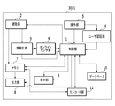
図1は、本実施例における画像形成装置の例として、MFP3001の構成を示すブロック図である。
FIG. 1 is a block diagram illustrating a configuration of an
制御部1は、MFP3001の各構成の制御をおこなう。操作部5は、ユーザからの操作・入力を受け付けるユーザインタフェースである。ユーザ認証部6は、MFP3001を使用するユーザのユーザ認証を管理する。読取部2は、印刷物のスキャンを行い、文書情報を生成する。また、読取部2は、文書情報に含まれるコード画像領域を抽出してメモリ7に格納する。情報化部3は、文書情報に含まれるコード画像を情報化することで埋め込み情報を得る。オンラインセンサ部4は、埋め込み情報を復号化することで、オンライン情報である複写禁止情報を取得する。
The
メモリ7は、スキャンにより得られた文書情報を記憶する。出力部8は、メモリ7から画像情報を読み出した後、画像情報の印刷、画像情報の外部装置への送信等の出力をする。ここで外部装置とは、例えばMFP3001とネットワークを介して接続されているPC等を指す。表示部9は、制御部1の制御により表示画面の表示を行う。データベース10は、MFP3001の設定情報(複写禁止情報、条件付複写禁止情報、又は追跡情報を含む)やログを記録する。ここで、追跡情報とは、文書情報を作成した者(又は印刷した者)を特定するための情報である。例えば、ユーザ名、印刷日時、印刷機(MFP3001)の機体番号などがこれに含まれる。文書情報を作成した者(又は印刷した者)を特定するための情報として印刷日時や機体番号が含まれるのは、これらとログ等の連携により、文書情報を作成した者(又は印刷した者)を特定することが可能になりうるからである。
The memory 7 stores document information obtained by scanning. The output unit 8 reads the image information from the memory 7 and then outputs the image information, such as printing the image information and transmitting the image information to an external device. Here, the external device refers to, for example, a PC connected to the MFP 3001 via a network. The display unit 9 displays a display screen under the control of the
エンコード部11は、複写禁止情報(又は条件付複写禁止情報)、及び追跡情報を符号化することで埋め込み情報を生成し、埋め込み情報を画像化することでコード画像を生成する。この符号化の際に、後述の通り、誤り訂正符号が加えられる。
The
次に、図1における各ブロックの処理の流れについて説明する。 Next, the processing flow of each block in FIG. 1 will be described.
まず、ユーザは、表示部9に表示された設定画面上を見ながら、ユーザID/パスワードを操作部5に対して入力する。入力された情報は、操作部5からユーザ認証部6に送信され、ユーザ認証部が、入力されたパスワードが適切なパスワードであるか判定する。判定の結果、パスワードが適切なパスワードである場合に、ユーザ認証部は、その旨とユーザIDを制御部1に送信する。
First, the user inputs the user ID / password to the
その後、印刷される画像に対して情報を埋め込むか否かの指示をユーザから受け付けるために、制御部1は、例えば、表示部9に、[情報埋込する]のチェックボックスを表示させる。さらに、ユーザがチェックボックスをチェックした場合、制御部1は、表示部9に、どの種類のコード画像で情報を付加するかユーザに問合せるための画面を表示させる。ユーザがここで入力した情報(すなわち、どの種類のコード画像で埋め込みを行うのかを示す情報、及び複写禁止又は条件付複製禁止情報のどちらを埋め込むのかを示す情報)は、制御部1が本体設定の情報としてデータベース10に格納する。その後、ユーザが操作部5を操作して印刷指示を行うと、操作部5がその旨を制御部1に送信する。なお、情報埋込の設定はMFP3001と接続されているPCのドライバやユーティリティ上からできることにしてもよい。一方、[情報埋込する]のチェックボックスがチェックされなかった場合、操作部5は、その旨を制御部1に送信する。さらに、ユーザは、[情報埋込する]のチェックボックスに対するチェックとは別に、印刷される画像に対して追跡情報を埋め込むか否かについて操作部5を介して設定することができる。ユーザによって設定された当該追跡情報を埋め込むか否かについての設定情報は、制御部1がデータベース10に格納する。
Thereafter, in order to receive an instruction from the user as to whether or not to embed information in the image to be printed, the
図2を参照して、制御部1の制御により行われる以降の処理を説明する。
With reference to FIG. 2, the subsequent processing performed under the control of the
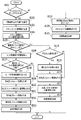
制御部1は、S101で、チェックボックスがチェックされたか否かを判定する。すなわち、制御部1は、印刷される画像に対して情報を埋め込む指示をユーザから受け付けたか否かを判断する。
In step S101, the
情報を埋め込む指示を受け付けた場合には、S102に移行し、受け付けていない場合には、S119に移行する。 If an instruction to embed information is accepted, the process proceeds to S102, and if not, the process proceeds to S119.
S102では、制御部1は、情報埋め込みの動作を設定し、その情報と今回の複写ユーザを特定するための情報(例、上記ユーザID)とをエンコード部11に送信する。制御部1は、読取部2に対して印刷物のスキャンを命じるコマンドを送信する。
In S <b> 102, the
S103では、読取部2は、印刷物のスキャンにより文書情報を生成し、当該文書情報をメモリ7と情報化部3に送信する。
In step S <b> 103, the
S104では、情報化部3は、送信されてきた文書情報からコード画像(第1のコード画像)を読み取り、情報化を行い、埋め込み情報を得る。情報化部3は、この埋め込み情報をオンラインセンサ部4に送信する。その後、オンラインセンサ部4は、埋め込み情報を復号(デコード)し、制御部1に結果を送信する。制御部1は、(1)複号できたかどうかの情報と、復号できた場合には復号した(2)コード画像の種類の情報と、(3)復号結果(埋め込み情報を復号した結果得られた情報)をデータペース部10に格納する。例えば、スキャンした文書内のQRコードの復号に成功した場合には、制御部1は、次の情報をデータベース部10に格納する。(1)複号に成功したという情報。(2)QRコードという情報。(3)復号結果(例えば、複写許可又は複写禁止を示す複写可否情報と追跡情報)。
In S104, the information processing unit 3 reads a code image (first code image) from the transmitted document information, performs information processing, and obtains embedded information. The information processing unit 3 transmits this embedded information to the online sensor unit 4. Thereafter, the online sensor unit 4 decodes the embedded information and transmits the result to the
S105では、制御部1がデータベース部10内の上記(1)の情報により、スキャンした文書からコード画像が読み出せたかを参照する。コード画像が読み出せて、かつ、(3)が複写許可を示していればS106に移行し、コード画像が読み出せていなければ、S114に移行する。なお、コード画像が読み出せて、かつ、(3)の情報が複写禁止を示す情報であった場合、当該スキャン画像の印刷処理を終了する(すなわち、図2に示すフローを抜ける)。
In S105, the
S106では、制御部1が、複号したコード画像種の情報と、MFP3001で新たに付加するコード画像種の情報とをデータベース部10から読み出し、図6に示すテーブルを参照し、スキャン文書から抽出したコード画像の再作成を行うかを判定する。コード画像の再作成の処理については後述する。ここで、MFP3001で新たに付加するコード画像種とは、ユーザがチェックボックスをチェック後に、操作部5から入力する、埋め込みコード画像の種類を指す。
In S <b> 106, the
例えば、複号したコード画像種がQRコードで、MFP3001で新たに付加するコード画像種がLVBC(Low Visibility Bar Code)であった場合、複号したコード画像の再作成は行うと判定する。なぜなら、QRコードの上にLVBCが合成されると、QRコードが読めなくなってしまうからである。すなわち、コード画像の再作成を行うか否かの判定は、スキャンした文書(原稿画像)に新たにコード画像を付加すると、当該文書に予め埋め込まれていたコード画像が読み出せなくなるか否かに応じて行う。
For example, when the decoded code image type is a QR code and the code image type newly added by the
従って、複号したコード画像種がLVBCで、MFP3001で新たに付加するコード画像種がQRコードであった場合、複号したコード画像の再作成は行わない。なぜなら、LVBCコードの上にQRコードが合成されLVBCの一部が消失してしまっても、LVBCコード内に埋め込まれている情報は読み出せるからである。この場合、スキャン文書から複号したコード画像を再作成処理する必要がないため、印刷完了までの時間が短縮できるというメリットも併せて得ることができる。
Therefore, when the decoded code image type is LVBC and the code image type newly added by the
また、別の例として、スキャン文書から抽出し、複号したコード画像種がLVBCで、埋め込みコード画像種がLVBCであった場合も、複号したコード画像の再作成は行わない。なぜなら、LVBCコードはスキャン文書全体に埋め込まれているため、LVBCコードを再作成するためには、スキャンされた文書画像からLVBCコードを除去する必要があり、この除去処理は多大な時間を要するためである。すなわち、予め埋め込まれていたコード画像を再作成するために、スキャンされた文書画像全体からコード画像を除去する必要がある場合、コード画像の再作成を行わない。この場合、前述のように、新たなコード画像の付加により予め埋め込まれていたコード画像が読み出せなくなる場合であっても、コード画像の再作成を行わない。 As another example, even if the code image type extracted from the scanned document and decoded is LVBC and the embedded code image type is LVBC, the decoded code image is not recreated. This is because, since the LVBC code is embedded in the entire scanned document, it is necessary to remove the LVBC code from the scanned document image in order to recreate the LVBC code, and this removal process takes a lot of time. It is. That is, when it is necessary to remove the code image from the entire scanned document image in order to recreate the code image embedded in advance, the code image is not recreated. In this case, as described above, the code image is not re-created even when the code image embedded in advance by the addition of a new code image cannot be read.
S107ではS106での決定に応じて処理が分岐する。複号したコード画像を再作成する場合、S108に移行する。複号したコード画像を再作成しない場合、S116に移行する。 In S107, the process branches according to the determination in S106. When re-creating the decoded code image, the process proceeds to S108. When the decoded code image is not recreated, the process proceeds to S116.
図7に、S108で行うコード画像情報書き換え処理の詳細な処理手順を示す。この処理は、図2のS112で合成されるコード画像に含ませる情報を決定する処理手順となっている。
まず、S201では、制御部1がデータベース10を参照し、埋め込み情報として、追跡情報を追加する必要があるかどうかを判定する。上述したように、ユーザによる操作部5の操作により、文書画像に追跡情報を付加するように設定されていた場合、追跡情報を追加する必要があると判定される。追跡情報を追加する必要が有る場合、S202に移行して、埋め込み情報として、追跡情報を追加する。即ち、S104で得られた追跡情報に対して、今回の追跡情報を追加する。なお、今回の追跡情報とは、操作部5を今回操作したユーザを特定するための情報である。例えば、ユーザ名、印刷日時、機体番号が、ユーザを特定するためのこの情報に含まれる。
FIG. 7 shows a detailed processing procedure of the code image information rewriting process performed in S108. This processing is a processing procedure for determining information to be included in the code image synthesized in S112 of FIG.
First, in S201, the
S203では、制御部1は、S104でデータベース部10に格納された、スキャン文書のコード画像に予め含まれていた情報(すなわち、第1のコード画像のデコードの結果)から複写可否情報を読み出す。なお、S104で読み取られたコード画像には、複写許可又は複写禁止のどちらかを示す複写可否情報が埋め込まれているものとする。この処理フローではS104で読み取られたコード画像の種類がQRコードであった場合の処理を説明する。
In S203, the
S204では、制御部1は、MFP3001で埋め込むコード画像(第2のコード画像)に含ませる情報(複写可否情報を含む)をデータベース部10から取得する。すなわち、制御部1は、第2のコード画像に係る複写可否情報(複写許可、複写禁止、又は条件付複写禁止を示す)を取得する。この処理フローでは、当該取得した複写可否情報をMFP3001により埋め込むコード画像の種類がLVBCである場合の処理を説明する。
In step S <b> 204, the
S205では、制御部1がS203とS204で抽出した情報及び図8に示すテーブルを参照し、再作成するコード画像に含ませる複写可否情報を変更するかを判定する。例えば、スキャン文書のコード画像(第1のコード画像、本実施例ではQRコード)が複写許可であり、MFP3001(本体)で新たに付加するコード画像(第2のコード画像、本実施例ではLVBC)が複写禁止である場合がある。この場合、再作成するコード画像(第3のコード画像、本実施例ではQRコード)の複写可否情報を複写禁止に設定する(即ち、複写許可を複写禁止に変更する)。このように、より厳しい条件の複写可否情報を設定するために、複写可否情報の変更の要否を判定する。
In S205, the
また、MFP3001で新たに付加するコード画像には、条件付複写禁止を示す複写可否情報を含ませることも可能である。条件付複写禁止とは、複写時にユーザIDやパスワードを求め、複写するかどうかを決定することである。例えば、スキャン文書のQRコードに複写許可を示す複写可否情報が埋め込まれており、MFP3001で付加するLVBCに条件付複写禁止を示す複写可否情報が埋め込まれている場合、再作成するQRコードに含ませる複写可否情報は複写禁止に変更する。複写禁止に変更する理由は次のとおりである。スキャン文書のQRコードに含まれる複写可否情報を変更せずにLVBCコードを合成して文書を作成すると、QRコードは複写許可を示し、LVBCコードは条件付複写禁止を示す文書が生成される。このような文書は、例えば、QRコードの情報は読み取れるが、LVBCコードの情報が読み取れない複写機において複写されてしまう。これを避けるため、再作成する画像コードには、本体で設定されている複写可否情報より厳しい条件の複写可否情報を設定する。なお、本実施例では、3種類の複写可否情報を例にして説明をしているが、これに限定されず、複写可否の条件は周知のものを適用することができ、上記と同様の方法で複写可否情報の変更の要否を判定することができる。
Further, the code image newly added by the
以上のように、再作成する画像コード(第3のコード画像、QRコード)には、MFP3001で新たに付加するコード画像(第2のコード画像、LVBC)に設定する複写可否情報と同じ、又はより厳しい条件の複写可否情報が設定される。このように設定することで、MFP3001で新たに付加した複写可否情報の設定に反して、文書が複写されてしまうことを防ぐことができる。
As described above, the re-created image code (third code image, QR code) is the same as the copy permission information set in the code image (second code image, LVBC) newly added by the
S206では、制御部1は、S205での判定結果に応じて、処理を分岐させる。再作成するコード画像に埋め込む複写可否情報を複写許可から複写禁止に変更する場合は、処理をS207に移行する。再作成するコード画像に埋め込む複写可否情報を変更しない場合、本フローを終了して、図2のS109に移行する。
In S206, the
S207では、制御部1が、データベース部10を参照し、再作成するコード画像の複写可否情報を複写許可から複写禁止に変更する。変更後に処理は、図2のS109に移行する。
In S207, the
S109では、制御部1は、本体設定の情報をデータベース部10から取得する。そして、制御部1は、エンコード部11にこれらの情報を符号化させ、画像化された埋め込み情報であるコード画像(第2のコード画像)を生成させる。そして、その生成されたコード画像をメモリ7に送信する。
In S <b> 109, the
S110では、制御部1は、メモリ7がS109で生成されたコード画像とS103で生成された文書情報を受取ったことを検知すると、メモリ7において両者を合成することで画像情報を生成する。すなわち、原稿画像に第2のコード画像を合成する。
In S110, when the
S111では、制御部1が、S108にて設定した複写可否情報と追跡情報を符号化することで符号化結果(埋め込み情報)を得て、その埋め込み情報を画像化することでコード画像(第3のコード画像)を生成する。すなわち、制御部1は、S104で読み取られた第1のコード画像のデコードの結果から第3のコード画像を生成する。なお、S108にて設定した複写可否情報は、複写許可と複写禁止の何れかを示す。S206でYESとなった場合には複写禁止、S206でNOとなった場合には複写許可を示すことになる。また、S108に設定した追跡情報も二種類が考えられる。第1の種類の追跡情報は、第1のコード画像に含まれていた追跡情報である(S201でNOになった場合)。第2の種類の追跡情報は、第1のコード画像に含まれていた追跡情報+今回の追跡情報である(S201でYESになった場合)。
In S111, the
S112では、制御部1は、S111で生成された第3のコード画像とS110で生成された画像情報とを合成することで画像情報を生成する。
In S112, the
すなわち、上記の処理によれば、原稿画像に第2のコード画像が合成され、当該第2のコード画像の上に第3のコード画像が合成される。このようにコード画像が合成されることによって、コード画像が予め含まれている原稿画像に新たにコード画像を付加することによって、当該予め埋め込まれていたコード画像が読み出せなくなることを回避することができる。 That is, according to the above processing, the second code image is synthesized with the original image, and the third code image is synthesized on the second code image. By combining the code image in this way, it is possible to avoid the case where the previously embedded code image cannot be read by newly adding the code image to the document image including the code image in advance. Can do.
S113において、制御部1は、生成した画像情報をメモリ7から出力部8に送信して、出力部8に印刷させる。
In S <b> 113, the
なお、上述したように[情報埋込する]のチェックボックスにチェックがされていない場合には、S119に処理が移行する。S119では、制御部1は、情報埋め込みの動作を設定せずに、読取部2に対して印刷物のスキャンを命じる。
As described above, when the check box of [Embed Information] is not checked, the process proceeds to S119. In S119, the
S120では、読取部2が印刷物のスキャンにより文書情報を生成して、メモリ7に送信する。なお、上述したように、ユーザが操作部5を介して印刷される画像に対して追跡情報を埋め込むように設定していた場合、生成された文書情報に対して今回の追跡情報を埋め込むことになる。即ち、今回の追跡情報を符号化し、それにより得られたコード画像を文書情報に合成することになる。ただし、スキャンにより生成された文書情報に予めコード画像が含まれており、当該コード画像に複写禁止を示す情報が含まれている場合には、当該スキャン画像の印刷処理を終了し、図2に示す処理を終了する(即ち、図2に示すフローチャートを抜ける。即ち、印刷はされない)。
In S <b> 120, the
その後、制御部1は、メモリ7が文書情報を受取ったことを検知すると、S121に移行し、生成した文書情報を画像情報としてメモリ7から出力部8に送信して、出力部8に印刷させる。
Thereafter, when the
次に、スキャン文書にコード画像が含まれていなかった場合の処理について述べる。S101において、チェックボックスがチェックされており、S105において、スキャン画像内にコード画像が含まれていなかった場合、制御部1は処理をS114に移行する。
Next, a process when a code image is not included in a scanned document will be described. If the check box is checked in S101 and the code image is not included in the scanned image in S105, the
S114では、制御部1がデータベース部10を参照して、埋め込むコード画像の埋め込み領域を変更するかどうかを表示部9に表示させる。ここで埋め込み領域を変更する理由を説明する。例えば、LVBCコードが埋め込み可能で、かつ、QRコードが認識できない複写機でQRコードが印字された文書を複写するケースを考える。文書をスキャンしても、文書中に含まれるQRコードは読み出せないため、複写機本体でLVBCコードを印字してしまうと、QRコードの領域もLVBCコードで上書きされて印字が行われてしまう。このため、印字された文書からQRコードが読み出せなくなってしまう。このようなケースを考慮し、他のコード画像で上書きされて予め印字されているコード画像が読めなくなる事を回避するために、本体で埋め込むコード画像の埋め込み領域を変更する処理を行う。例えば、ユーザが操作部5を操作し、変更を選択した場合、処理をS115に移行する。ユーザが変更を選択しなかった場合、処理をS116に移行する。
In S <b> 114, the
S115では、制御部1がデータベース部10を参照し、図9に示すような埋め込み領域フォーマットを表示部9に表示させる。ユーザはいずれかを選択すると、制御部1はユーザが選択した埋め込み領域パターンをデータベース部10に格納して処理をS116に移行する。
In S115, the
S116では、制御部1は、本体で設定された複写可否情報、追跡情報(ユーザIDを含む、スキャン文書に元々、含まれていた情報)、及びユーザが選択した埋め込みパターンをデータベース部10から取得する。そして、制御部1は、エンコード部11にこれらの情報を符号化させ、得られた符号化結果(埋め込み情報)を画像化させることで、コード画像を生成させる。そして、制御部1は、その生成されたコード画像をメモリ7に送信する。
In S116, the
その後、制御部1は、メモリ7がコード画像と文書情報を受取ったことを検知すると、S117に移行し、メモリ7において両者を合成することで画像情報を生成する。
Thereafter, when the
そして、S118において、生成した画像情報をメモリ7から出力部8に送信して、出力部8に印刷させる。 In step S <b> 118, the generated image information is transmitted from the memory 7 to the output unit 8 and is printed on the output unit 8.
また、S107にて、制御部1が、読み取ったコード画像の再作成が必要ないと判断した場合、処理をS116に移行する。
If the
S116では、制御部1は、本体で設定された複写可否情報と追跡情報(ユーザIDを含む、スキャン文書に元々、含まれていた情報)をデータベース部10から抽出する。そして、制御部1は、エンコード部11にこれらの情報を符号化させ、得られた符号化結果(埋め込み情報)を画像化することでコード画像を生成させる。そして、制御部1は、その生成されたコード画像をメモリ7に送信する。
In S116, the
その後、制御部1は、メモリ7がコード画像と文書情報を受取ったことを検知すると、S117に移行し、メモリ7において両者を合成することで画像情報を生成する。そして、S118において、生成した画像情報をメモリ7から出力部8に送信して、出力部8に印刷させる。
Thereafter, when the
なお、上記追跡情報には、例えば、印刷日時、印刷指示をしたユーザのユーザ名(即ち、ユーザID)、デバイス名といった情報等、印刷者を特定するために有用な情報が含まれる。本明細書における追跡情報の定義は、印刷者を特定するために使いうる情報である。 The tracking information includes information useful for specifying the printer, such as information such as the printing date and time, the user name (that is, user ID) of the user who issued the printing instruction, and the device name. The definition of tracking information in this specification is information that can be used to identify a printer.
ここで、図3及び図5を用いて、複写可否情報及び追跡情報を符号化して、符号化結果を画像化する方法の一例を説明する。 Here, an example of a method for encoding the copy permission / inhibition information and the tracking information and imaging the encoded result will be described with reference to FIGS. 3 and 5.
図5は、単位コード画像1600を説明するための補足図である。
単位コード画像1600は、1cm×1cm程度であり、高密度領域(1605〜8)と低密度領域1609〜1612とからなる。
FIG. 5 is a supplementary diagram for explaining the
The
この高密度領域には、禁止情報の符号化結果が含まれ、低密度領域には、追跡情報の符号化結果が含まれる。なお、高密度領域では低密度領域に比べて誤り訂正符号が多量に使われる(禁止情報の方が追跡情報よりも重要な情報であるという思想がその中にはある)。なお、誤り訂正符号が多量に使われるにも関わらず、禁止情報の含まれる領域の方が小さいのは、禁止情報の方がデータサイズが小さいからである。なお、この単位コード画像1600は、文書情報全面に対して繰り返し合成されることになる。
This high density area includes the encoding result of the prohibition information, and the low density area includes the encoding result of the tracking information. In the high-density area, a larger amount of error correction codes are used than in the low-density area (the idea is that prohibited information is more important information than tracking information). It should be noted that although the error correction code is used in a large amount, the area including the prohibition information is smaller because the prohibition information has a smaller data size. The
例えば、文書情報がA4サイズ(21cm×29.7cm)のシートに印刷されるにあたり、単位コード画像は、21×29個だけ文書情報に合成されることになる。これにより、同じ情報が609個、合成されることになる。 For example, when document information is printed on a sheet of A4 size (21 cm × 29.7 cm), only 21 × 29 unit code images are combined with the document information. As a result, 609 pieces of the same information are combined.
本明細書では、文書情報に合成される全ての単位コード画像(609個の単位コード画像)又は一部の単位コード画像をコード画像と称する。 In this specification, all unit code images (609 unit code images) or a part of unit code images combined with document information are referred to as code images.
図3は、図5に示す各領域1605の中にどのようなドットが含まれているかを示す図である。この中には、情報ドット1401および、配列ドット1402が含まれている。配列ドット1402は、点線で示されるリファレンスグリッド1403の上に定間隔で(即ち、リファレンスグリッド1403同士の交点の上に)存在する。そして、情報ドットは、このリファレンスグリッド1403同士の交点からずれた位置に存在する。
FIG. 3 is a diagram showing what kind of dots are included in each
このずれた方向(交点に対する前記ずれた位置のずれ方向)で、複写可否情報の符号化結果が表現されることになる。言い換えると、複写可否情報が符号化されて得られた埋込情報(の一部である、複写可否情報の符号化結果)を画像化すると、情報ドット1401および配列ドット1402を領域1606に含む単位コード画像ができることになる。
In this shifted direction (the shifted direction of the shifted position with respect to the intersection), the encoding result of the copy permission / inhibition information is expressed. In other words, when the embedding information obtained by encoding the copy permission / inhibition information (a copy result of the copy permission / inhibition information which is a part of the embedded information) is imaged, a unit including the
他の領域1606〜1608についても、同じ情報を同じ方法で画像化することで得られた、同じドットが含まれる(冗長性確保のため)。
The
なお、領域1609〜1612については、埋め込み情報(の一部である、追跡情報の符号化結果)を画像化することで得られたドットが含まれることになるが、画像化の手法は、領域1605〜1608と同じである。
Note that the
なお、(i)複写可否情報及び/又は追跡情報を符号化して埋込情報とし、(ii)この埋込情報を画像化することで単位コード画像を作成し、(iii)単位コード画像を縦横に(例、609個)並べる処理の全てをもって、本明細書では、エンコードと称する。エンコードを行うのは、エンコード部11である。
Note that (i) copy permission / inhibition information and / or tracking information is encoded into embedded information, (ii) a unit code image is created by imaging this embedded information, and (iii) the unit code image is vertically and horizontally In the present specification, all of the processing of arranging (for example, 609) is referred to as encoding. The
さて、上記リファレンスグリッドであるが、図3では、点線で描かれているものの、実際には印刷されない線である。 The reference grid is a line that is drawn in dotted lines in FIG. 3 but is not actually printed.
図4を参照して、この仮想的な線をどのように見つけ出すのかについて説明する。これは、情報化部によって行われる処理である。まず、情報化部3は、任意のドット1501を選択する。そして、情報化部3は、当該選択されたドットの周辺に存在する任意のドット1502を選択する。そして、情報化部3は、これら選択したドットの位置を、両ドットの中心点を中心として90°回転する。回転により得られた位置にドットが存在する場合には、上記選択された各ドットは、縦横共に等間隔に存在しているはずの配列ドットであると情報化部3は判断する。
With reference to FIG. 4, how this virtual line is found will be described. This is a process performed by the information processing unit. First, the information processing unit 3 selects an
一方、存在しない場合には、選択された各ドットは、ランダムな位置に存在しているはずの情報ドットであると情報化部3は判断する。このようにして、情報化部3は、二つの配列ドットを見つけ出し、あとは、配列ドットが縦横共に等間隔に存在しているという制約条件を利用して、他の全ての配列ドットを見つけ出すのである。 On the other hand, if it does not exist, the information processing unit 3 determines that each selected dot is an information dot that should be present at a random position. In this way, the information processing unit 3 finds two array dots, and then finds all other array dots using the constraint that array dots exist at equal intervals both vertically and horizontally. is there.
配列ドットを全て見つけ出した後は、情報化部3は、これら配列ドット上にリファレンスグリッドを仮想的に引き、最後にリファレンスグリッド同士の交点からの、残りのドット(即ち、情報ドット)のずれ方向を求め、埋込情報を得るのである。 After finding all the array dots, the information processing unit 3 virtually draws a reference grid on these array dots, and finally, the direction of deviation of the remaining dots (ie, information dots) from the intersection of the reference grids To obtain embedded information.
なお、本明細書においては、上方向にずれている場合に“0”、右上方向にずれている場合に“1”、右方向にずれている場合に“2”というようにして、ドットから情報を得る。 In the present specification, “0” is displayed when the position is shifted upward, “1” is displayed when the position is shifted rightward, and “2” is displayed when the position is shifted rightward. get information.
[その他の実施例]
また、本発明は、以下の処理を実行することによっても実現される。即ち、上述した実施形態の機能を実現するソフトウェア(プログラム)を、ネットワーク又は各種記憶媒体を介してシステム或いは装置に供給し、そのシステム或いは装置のコンピュータ(またはCPUやMPU等)がプログラムを読み出して実行する処理である。
[Other Examples]
The present invention can also be realized by executing the following processing. That is, software (program) that realizes the functions of the above-described embodiments is supplied to a system or apparatus via a network or various storage media, and a computer (or CPU, MPU, etc.) of the system or apparatus reads the program. It is a process to be executed.
Claims (8)
前記判定する手段により読み込めなくなると判定された場合、前記第1のコード画像をデコードし、当該デコードの結果を含む第3のコード画像を生成する生成手段と、
前記画像に対して前記第2のコード画像を合成し、当該合成結果の上に前記第3のコード画像を合成する手段と
を備えたことを特徴とする画像形成装置。 Means for determining whether or not the first code image cannot be read when the second code image is synthesized with the image including the first code image;
Generating means for decoding the first code image and generating a third code image including a result of the decoding when it is determined by the determining means that reading is impossible;
An image forming apparatus comprising: means for synthesizing the second code image with the image, and synthesizing the third code image on the synthesis result .
前記判定するステップにより読み込めなくなると判定された場合、前記第1のコード画像をデコードし、当該デコードの結果を含む第3のコード画像を生成する生成ステップと、
前記画像に対して前記第2のコード画像を合成し、当該合成結果の上に前記第3のコード画像を合成するステップと
を含むことを特徴とする画像形成方法。 Determining whether or not the first code image cannot be read when the second code image is synthesized with the image including the first code image;
A generation step of decoding the first code image and generating a third code image including a result of the decoding when it is determined in the determining step that reading is impossible;
Image forming method characterized by comprising the step of the second code image by combining on the image, combining the third code image on the the combined results.
前記取得した画像内に第1の種類のコード画像または第2の種類のコード画像が含まれているかを判定する手段と、
第1の種類のコード画像または第2の種類のコード画像を前記取得した画像に埋め込むべきであるかを判定する手段と、
生成手段であって、
前記取得した画像内に第1の種類のコード画像が含まれており、かつ第2の種類のコード画像を前記取得した画像に埋め込むべきであると判定された場合に、
前記取得した画像内の第1の種類のコード画像に含まれる情報を含む第1の種類のコード画像を生成し、前記取得した画像に対して第2の種類のコード画像を合成して合成画像を取得し、該合成画像に対して前記生成した第1の種類のコード画像を合成して別の合成画像を取得し、取得した該別の合成画像を出力し、
前記取得した画像内に第2の種類のコード画像が含まれており、かつ第1の種類のコード画像を前記取得した画像に埋め込むべきであると判定された場合に、
前記取得した画像に対して第1の種類のコード画像を合成して合成画像を取得し、該取得した合成画像を出力する、生成手段と
を備え、
第2の種類のコード画像は、第1の種類のコード画像よりも広い範囲を持つコード画像である
ことを特徴とする画像形成装置。 Means for acquiring an image by scanning a printed matter;
Means for determining whether the acquired image includes a first type code image or a second type code image;
Means for determining whether a first type code image or a second type code image should be embedded in the acquired image;
Means for generating,
When it is determined that a first type code image is included in the acquired image and a second type code image should be embedded in the acquired image,
Combining the first type of code image including the information contained in the first type of code image of the acquired in image form raw synthesizes the second type of code image to the acquired image acquiring an image, get another composite image by combining the first type of code image forms before Kisei respect to the composite image, and outputs a composite image of said further acquired,
If it is determined that a second type code image is included in the acquired image and the first type code image should be embedded in the acquired image,
Generating means for synthesizing a first type code image to the obtained image to obtain a synthesized image, and outputting the obtained synthesized image;
The second type of code image, the image forming apparatus which is a code image having a wider range than the first type of code image.
前記取得した画像内に第1の種類のコード画像または第2の種類のコード画像が含まれているかを判定するステップと、
第1の種類のコード画像または第2の種類のコード画像を前記取得した画像に埋め込むべきであるかを判定するステップと、
生成ステップであって、
前記取得した画像内に第1の種類のコード画像が含まれており、かつ第2の種類のコード画像を前記取得した画像に埋め込むべきであると判定された場合に、
前記取得した画像内の第1の種類のコード画像に含まれる情報を含む第1の種類のコード画像を生成し、前記取得した画像に対して第2の種類のコード画像を合成して合成画像を取得し、該合成画像に対して前記生成した第1の種類のコード画像を合成して別の合成画像を取得し、取得した該別の合成画像を出力し、
前記取得した画像内に第2の種類のコード画像が含まれており、かつ第1の種類のコード画像を前記取得した画像に埋め込むべきであると判定された場合に、
前記取得した画像に対して第1の種類のコード画像を合成して合成画像を取得し、該取得した合成画像を出力する、生成ステップと
を含み、
第2の種類のコード画像は、第1の種類のコード画像よりも広い範囲を持つコード画像である
ことを特徴とする画像形成方法。 Acquiring an image by scanning a printed material;
Determining whether a first type code image or a second type code image is included in the acquired image;
Determining whether a first type code image or a second type code image should be embedded in the acquired image;
A generation step,
When it is determined that a first type code image is included in the acquired image and a second type code image should be embedded in the acquired image,
Combining the first type of code image including the information contained in the first type of code image of the acquired in image form raw synthesizes the second type of code image to the acquired image acquiring an image, get another composite image by combining the first type of code image forms before Kisei respect to the composite image, and outputs a composite image of said further acquired,
If it is determined that a second type code image is included in the acquired image and the first type code image should be embedded in the acquired image,
By combining the first type of code image to the acquired image to acquire the synthetic image, and outputs the composite image the acquired, and a generating step,
The second type of code image, an image forming method which is a code image having a wider range than the first type of code image.
Priority Applications (4)
| Application Number | Priority Date | Filing Date | Title |
|---|---|---|---|
| JP2010165064A JP5550481B2 (en) | 2009-08-12 | 2010-07-22 | Image forming apparatus, image forming method, and program |
| US12/851,004 US8384966B2 (en) | 2009-08-12 | 2010-08-05 | Image forming device and image forming method |
| CN2010102501444A CN101998015A (en) | 2009-08-12 | 2010-08-06 | Image forming device and image forming method |
| EP10172580.2A EP2299687B1 (en) | 2009-08-12 | 2010-08-12 | Image forming device and image forming method |
Applications Claiming Priority (3)
| Application Number | Priority Date | Filing Date | Title |
|---|---|---|---|
| JP2009187376 | 2009-08-12 | ||
| JP2009187376 | 2009-08-12 | ||
| JP2010165064A JP5550481B2 (en) | 2009-08-12 | 2010-07-22 | Image forming apparatus, image forming method, and program |
Publications (3)
| Publication Number | Publication Date |
|---|---|
| JP2011061764A JP2011061764A (en) | 2011-03-24 |
| JP2011061764A5 JP2011061764A5 (en) | 2013-05-23 |
| JP5550481B2 true JP5550481B2 (en) | 2014-07-16 |
Family
ID=43430687
Family Applications (1)
| Application Number | Title | Priority Date | Filing Date |
|---|---|---|---|
| JP2010165064A Expired - Fee Related JP5550481B2 (en) | 2009-08-12 | 2010-07-22 | Image forming apparatus, image forming method, and program |
Country Status (4)
| Country | Link |
|---|---|
| US (1) | US8384966B2 (en) |
| EP (1) | EP2299687B1 (en) |
| JP (1) | JP5550481B2 (en) |
| CN (1) | CN101998015A (en) |
Families Citing this family (5)
| Publication number | Priority date | Publication date | Assignee | Title |
|---|---|---|---|---|
| JP5570245B2 (en) * | 2010-02-24 | 2014-08-13 | キヤノン株式会社 | Apparatus, method, and program |
| JP5251963B2 (en) * | 2010-11-16 | 2013-07-31 | コニカミノルタビジネステクノロジーズ株式会社 | Image processing system, image processing server, image forming apparatus, image processing method, and image processing program |
| JP5264945B2 (en) * | 2011-03-01 | 2013-08-14 | キヤノン株式会社 | Apparatus, method, and program |
| JP6289066B2 (en) * | 2013-12-09 | 2018-03-07 | キヤノン株式会社 | Information processing apparatus, method, and program |
| JP2015225176A (en) * | 2014-05-27 | 2015-12-14 | キヤノン株式会社 | Image processor, control method thereof, and program |
Family Cites Families (17)
| Publication number | Priority date | Publication date | Assignee | Title |
|---|---|---|---|---|
| SE517445C2 (en) | 1999-10-01 | 2002-06-04 | Anoto Ab | Position determination on a surface provided with a position coding pattern |
| JP3997720B2 (en) * | 2001-04-05 | 2007-10-24 | 富士ゼロックス株式会社 | Image processing apparatus and image forming apparatus |
| JP2003008864A (en) * | 2001-06-18 | 2003-01-10 | Ricoh Co Ltd | Imaging device |
| US7145556B2 (en) * | 2001-10-29 | 2006-12-05 | Anoto Ab | Method and device for decoding a position-coding pattern |
| JP4251629B2 (en) * | 2003-01-31 | 2009-04-08 | キヤノン株式会社 | Image processing system, information processing apparatus, control method, computer program, and computer-readable storage medium |
| JP2006087034A (en) | 2004-09-17 | 2006-03-30 | Ricoh Co Ltd | Image control system, image controller, device for forming image, method for controlling image, image control program and recording medium |
| CN101167084B (en) | 2005-04-28 | 2010-05-12 | 吉田健治 | Information I/O method using dot pattern |
| JP2007013482A (en) * | 2005-06-29 | 2007-01-18 | Sharp Corp | Image forming apparatus, image forming method, control program and computer-readable recording medium |
| JP4164523B2 (en) * | 2005-09-30 | 2008-10-15 | キヤノン株式会社 | Image processing system |
| JP4595789B2 (en) * | 2005-11-17 | 2010-12-08 | 富士ゼロックス株式会社 | Image processing apparatus, image processing method, and image processing program |
| CN100364326C (en) | 2005-12-01 | 2008-01-23 | 北京北大方正电子有限公司 | Method and apparatus for embedding and detecting digital watermark in text file |
| US7778465B2 (en) * | 2007-02-14 | 2010-08-17 | Kabushiki Kaisha Toshiba | Image forming apparatus with a plurality of functions |
| JP4828448B2 (en) * | 2007-02-16 | 2011-11-30 | 株式会社リコー | Image processing apparatus, image processing method, and image processing program |
| JP4343968B2 (en) * | 2007-03-13 | 2009-10-14 | キヤノン株式会社 | Image forming apparatus and method |
| JP5159345B2 (en) * | 2007-09-03 | 2013-03-06 | キヤノン株式会社 | Device, method, and program for handling embedded code |
| CN101221625B (en) * | 2008-01-24 | 2011-06-22 | 天津市阿波罗信息技术有限公司 | Processing method capable of embedding information on bar code |
| JP5147429B2 (en) * | 2008-01-28 | 2013-02-20 | キヤノン株式会社 | Image processing apparatus, image processing method, and program thereof |
-
2010
- 2010-07-22 JP JP2010165064A patent/JP5550481B2/en not_active Expired - Fee Related
- 2010-08-05 US US12/851,004 patent/US8384966B2/en not_active Expired - Fee Related
- 2010-08-06 CN CN2010102501444A patent/CN101998015A/en active Pending
- 2010-08-12 EP EP10172580.2A patent/EP2299687B1/en active Active
Also Published As
| Publication number | Publication date |
|---|---|
| US20110038015A1 (en) | 2011-02-17 |
| EP2299687A1 (en) | 2011-03-23 |
| JP2011061764A (en) | 2011-03-24 |
| US8384966B2 (en) | 2013-02-26 |
| EP2299687B1 (en) | 2019-10-09 |
| CN101998015A (en) | 2011-03-30 |
Similar Documents
| Publication | Publication Date | Title |
|---|---|---|
| JP4343968B2 (en) | Image forming apparatus and method | |
| JP5550481B2 (en) | Image forming apparatus, image forming method, and program | |
| JP2007300602A (en) | Method and device for authenticating printed copy | |
| JP5366657B2 (en) | System, method and program | |
| JP5328456B2 (en) | Image processing apparatus, image processing method, program, and storage medium | |
| US9509880B2 (en) | Device capable of reading plural documents, method of controlling the device, and program | |
| JP2012156697A (en) | Image forming apparatus, control method thereof, and program | |
| JP5478965B2 (en) | Image forming apparatus, image forming method, and program | |
| JP2007060220A (en) | Image forming apparatus | |
| JP2008182552A (en) | Image processor, image processing system and program | |
| CN101123663B (en) | Image processing device and method | |
| JP4853308B2 (en) | Image processing apparatus and image processing program | |
| US7952750B2 (en) | Image processing apparatus and image processing method | |
| JP5570245B2 (en) | Apparatus, method, and program | |
| JP5550377B2 (en) | Image forming apparatus, image forming method, and program for detecting and processing code | |
| JP2010206399A (en) | Image processing apparatus, method and program | |
| JP2007328487A (en) | Two dimensional code generation device, two dimensional code generation method, two dimensional code generation program, information embedding device, information embedding method, information embedding program, and two dimensional code | |
| JP2012244206A (en) | Image forming apparatus | |
| JP6717251B2 (en) | Image forming apparatus and image forming program | |
| JP5717890B2 (en) | Image forming apparatus, control method thereof, and program | |
| JP4587492B2 (en) | Image forming apparatus and method | |
| JP2012049978A (en) | Image processing apparatus capable of processing code image, control method thereof, and program thereof | |
| JP2013219492A (en) | Image forming apparatus | |
| JP2008042840A (en) | Image reading method, method of controlling image reading apparatus | |
| JP2008153853A (en) | Image input/output system, document image output device, document image input/output device, image input/output method, and image input/output program |
Legal Events
| Date | Code | Title | Description |
|---|---|---|---|
| A521 | Written amendment |
Free format text: JAPANESE INTERMEDIATE CODE: A523 Effective date: 20130409 |
|
| A621 | Written request for application examination |
Free format text: JAPANESE INTERMEDIATE CODE: A621 Effective date: 20130409 |
|
| A977 | Report on retrieval |
Free format text: JAPANESE INTERMEDIATE CODE: A971007 Effective date: 20140218 |
|
| A131 | Notification of reasons for refusal |
Free format text: JAPANESE INTERMEDIATE CODE: A131 Effective date: 20140311 |
|
| A521 | Written amendment |
Free format text: JAPANESE INTERMEDIATE CODE: A523 Effective date: 20140325 |
|
| TRDD | Decision of grant or rejection written | ||
| A01 | Written decision to grant a patent or to grant a registration (utility model) |
Free format text: JAPANESE INTERMEDIATE CODE: A01 Effective date: 20140422 |
|
| A61 | First payment of annual fees (during grant procedure) |
Free format text: JAPANESE INTERMEDIATE CODE: A61 Effective date: 20140520 |
|
| R151 | Written notification of patent or utility model registration |
Ref document number: 5550481 Country of ref document: JP Free format text: JAPANESE INTERMEDIATE CODE: R151 |
|
| LAPS | Cancellation because of no payment of annual fees |