JP4251629B2 - Image processing system, information processing apparatus, control method, computer program, and computer-readable storage medium - Google Patents
Image processing system, information processing apparatus, control method, computer program, and computer-readable storage medium Download PDFInfo
- Publication number
- JP4251629B2 JP4251629B2 JP2003415485A JP2003415485A JP4251629B2 JP 4251629 B2 JP4251629 B2 JP 4251629B2 JP 2003415485 A JP2003415485 A JP 2003415485A JP 2003415485 A JP2003415485 A JP 2003415485A JP 4251629 B2 JP4251629 B2 JP 4251629B2
- Authority
- JP
- Japan
- Prior art keywords
- vectorization
- image
- character
- attribute
- data
- Prior art date
- Legal status (The legal status is an assumption and is not a legal conclusion. Google has not performed a legal analysis and makes no representation as to the accuracy of the status listed.)
- Expired - Fee Related
Links
Images


Classifications
-
- H—ELECTRICITY
- H04—ELECTRIC COMMUNICATION TECHNIQUE
- H04N—PICTORIAL COMMUNICATION, e.g. TELEVISION
- H04N1/00—Scanning, transmission or reproduction of documents or the like, e.g. facsimile transmission; Details thereof
- H04N1/00127—Connection or combination of a still picture apparatus with another apparatus, e.g. for storage, processing or transmission of still picture signals or of information associated with a still picture
- H04N1/00326—Connection or combination of a still picture apparatus with another apparatus, e.g. for storage, processing or transmission of still picture signals or of information associated with a still picture with a data reading, recognizing or recording apparatus, e.g. with a bar-code apparatus
- H04N1/00328—Connection or combination of a still picture apparatus with another apparatus, e.g. for storage, processing or transmission of still picture signals or of information associated with a still picture with a data reading, recognizing or recording apparatus, e.g. with a bar-code apparatus with an apparatus processing optically-read information
- H04N1/00331—Connection or combination of a still picture apparatus with another apparatus, e.g. for storage, processing or transmission of still picture signals or of information associated with a still picture with a data reading, recognizing or recording apparatus, e.g. with a bar-code apparatus with an apparatus processing optically-read information with an apparatus performing optical character recognition
-
- G—PHYSICS
- G06—COMPUTING; CALCULATING OR COUNTING
- G06V—IMAGE OR VIDEO RECOGNITION OR UNDERSTANDING
- G06V30/00—Character recognition; Recognising digital ink; Document-oriented image-based pattern recognition
- G06V30/10—Character recognition
- G06V30/14—Image acquisition
- G06V30/1444—Selective acquisition, locating or processing of specific regions, e.g. highlighted text, fiducial marks or predetermined fields
-
- H—ELECTRICITY
- H04—ELECTRIC COMMUNICATION TECHNIQUE
- H04N—PICTORIAL COMMUNICATION, e.g. TELEVISION
- H04N1/00—Scanning, transmission or reproduction of documents or the like, e.g. facsimile transmission; Details thereof
- H04N1/00127—Connection or combination of a still picture apparatus with another apparatus, e.g. for storage, processing or transmission of still picture signals or of information associated with a still picture
- H04N1/00204—Connection or combination of a still picture apparatus with another apparatus, e.g. for storage, processing or transmission of still picture signals or of information associated with a still picture with a digital computer or a digital computer system, e.g. an internet server
- H04N1/00244—Connection or combination of a still picture apparatus with another apparatus, e.g. for storage, processing or transmission of still picture signals or of information associated with a still picture with a digital computer or a digital computer system, e.g. an internet server with a server, e.g. an internet server
-
- H—ELECTRICITY
- H04—ELECTRIC COMMUNICATION TECHNIQUE
- H04N—PICTORIAL COMMUNICATION, e.g. TELEVISION
- H04N1/00—Scanning, transmission or reproduction of documents or the like, e.g. facsimile transmission; Details thereof
- H04N1/00127—Connection or combination of a still picture apparatus with another apparatus, e.g. for storage, processing or transmission of still picture signals or of information associated with a still picture
- H04N1/00326—Connection or combination of a still picture apparatus with another apparatus, e.g. for storage, processing or transmission of still picture signals or of information associated with a still picture with a data reading, recognizing or recording apparatus, e.g. with a bar-code apparatus
- H04N1/00328—Connection or combination of a still picture apparatus with another apparatus, e.g. for storage, processing or transmission of still picture signals or of information associated with a still picture with a data reading, recognizing or recording apparatus, e.g. with a bar-code apparatus with an apparatus processing optically-read information
- H04N1/00334—Connection or combination of a still picture apparatus with another apparatus, e.g. for storage, processing or transmission of still picture signals or of information associated with a still picture with a data reading, recognizing or recording apparatus, e.g. with a bar-code apparatus with an apparatus processing optically-read information with an apparatus processing barcodes or the like
-
- H—ELECTRICITY
- H04—ELECTRIC COMMUNICATION TECHNIQUE
- H04N—PICTORIAL COMMUNICATION, e.g. TELEVISION
- H04N1/00—Scanning, transmission or reproduction of documents or the like, e.g. facsimile transmission; Details thereof
- H04N1/0035—User-machine interface; Control console
- H04N1/00352—Input means
- H04N1/00355—Mark-sheet input
- H04N1/00358—Type of the scanned marks
- H04N1/00363—Bar codes or the like
-
- H—ELECTRICITY
- H04—ELECTRIC COMMUNICATION TECHNIQUE
- H04N—PICTORIAL COMMUNICATION, e.g. TELEVISION
- H04N1/00—Scanning, transmission or reproduction of documents or the like, e.g. facsimile transmission; Details thereof
- H04N1/21—Intermediate information storage
- H04N1/2166—Intermediate information storage for mass storage, e.g. in document filing systems
-
- G—PHYSICS
- G06—COMPUTING; CALCULATING OR COUNTING
- G06V—IMAGE OR VIDEO RECOGNITION OR UNDERSTANDING
- G06V30/00—Character recognition; Recognising digital ink; Document-oriented image-based pattern recognition
- G06V30/10—Character recognition
-
- H—ELECTRICITY
- H04—ELECTRIC COMMUNICATION TECHNIQUE
- H04N—PICTORIAL COMMUNICATION, e.g. TELEVISION
- H04N1/00—Scanning, transmission or reproduction of documents or the like, e.g. facsimile transmission; Details thereof
- H04N1/32—Circuits or arrangements for control or supervision between transmitter and receiver or between image input and image output device, e.g. between a still-image camera and its memory or between a still-image camera and a printer device
- H04N1/32101—Display, printing, storage or transmission of additional information, e.g. ID code, date and time or title
- H04N1/32128—Display, printing, storage or transmission of additional information, e.g. ID code, date and time or title attached to the image data, e.g. file header, transmitted message header, information on the same page or in the same computer file as the image
- H04N1/32133—Display, printing, storage or transmission of additional information, e.g. ID code, date and time or title attached to the image data, e.g. file header, transmitted message header, information on the same page or in the same computer file as the image on the same paper sheet, e.g. a facsimile page header
-
- H—ELECTRICITY
- H04—ELECTRIC COMMUNICATION TECHNIQUE
- H04N—PICTORIAL COMMUNICATION, e.g. TELEVISION
- H04N2201/00—Indexing scheme relating to scanning, transmission or reproduction of documents or the like, and to details thereof
- H04N2201/0077—Types of the still picture apparatus
- H04N2201/0094—Multifunctional device, i.e. a device capable of all of reading, reproducing, copying, facsimile transception, file transception
-
- H—ELECTRICITY
- H04—ELECTRIC COMMUNICATION TECHNIQUE
- H04N—PICTORIAL COMMUNICATION, e.g. TELEVISION
- H04N2201/00—Indexing scheme relating to scanning, transmission or reproduction of documents or the like, and to details thereof
- H04N2201/32—Circuits or arrangements for control or supervision between transmitter and receiver or between image input and image output device, e.g. between a still-image camera and its memory or between a still-image camera and a printer device
- H04N2201/3201—Display, printing, storage or transmission of additional information, e.g. ID code, date and time or title
- H04N2201/3225—Display, printing, storage or transmission of additional information, e.g. ID code, date and time or title of data relating to an image, a page or a document
- H04N2201/3226—Display, printing, storage or transmission of additional information, e.g. ID code, date and time or title of data relating to an image, a page or a document of identification information or the like, e.g. ID code, index, title, part of an image, reduced-size image
-
- H—ELECTRICITY
- H04—ELECTRIC COMMUNICATION TECHNIQUE
- H04N—PICTORIAL COMMUNICATION, e.g. TELEVISION
- H04N2201/00—Indexing scheme relating to scanning, transmission or reproduction of documents or the like, and to details thereof
- H04N2201/32—Circuits or arrangements for control or supervision between transmitter and receiver or between image input and image output device, e.g. between a still-image camera and its memory or between a still-image camera and a printer device
- H04N2201/3201—Display, printing, storage or transmission of additional information, e.g. ID code, date and time or title
- H04N2201/3271—Printing or stamping
Landscapes
- Engineering & Computer Science (AREA)
- Multimedia (AREA)
- Signal Processing (AREA)
- Computer Vision & Pattern Recognition (AREA)
- General Engineering & Computer Science (AREA)
- Theoretical Computer Science (AREA)
- General Physics & Mathematics (AREA)
- Computing Systems (AREA)
- Physics & Mathematics (AREA)
- Processing Or Creating Images (AREA)
- Editing Of Facsimile Originals (AREA)
- Image Processing (AREA)
- Character Discrimination (AREA)
- Information Retrieval, Db Structures And Fs Structures Therefor (AREA)
- Compression Of Band Width Or Redundancy In Fax (AREA)
- Record Information Processing For Printing (AREA)
Description
本願発明は、印刷された原稿を読み取り電子化する技術に関するものである。 The present invention relates to a technique for reading and digitizing a printed document.
近年、環境問題が叫ばれる中、オフィスでのペーパーレス化が急速に進んでおり、電子文書を取り扱う各種技術が考え出されている。 In recent years, as environmental problems have been screamed, paperless offices have been rapidly developed, and various technologies for handling electronic documents have been devised.
例えば、紙文書を電子文書にする手法として、紙文書をスキャナーで読み取り、電子文書フォーマット(JPEGなど)に変換して送信するものがある(特許文献1)。しかしながら、この特許文献1に開示された技術では、スキャナーで読み取った画像をJPEGなどの電子文書に変換することを目的とするものであるので、プリントされた文書を用いて、保存されているファイルを検索することなどは何ら考慮していない。したがって、プリントとスキャンを繰り返すことになってしまい、変換された電子文書の画像は徐々に劣化していってしまうという問題がある。
For example, as a technique for converting a paper document into an electronic document, there is a technique in which a paper document is read by a scanner, converted into an electronic document format (such as JPEG) and transmitted (Patent Document 1). However, since the technique disclosed in
また、文書データを属性毎の領域に分けて、各領域は全て生画像データ(或いは圧縮画像データ)として保管することが考えられているが(特許文献2)、各領域はイメージとして扱うため、ファイル容量も大きくなってしまうし、拡大等の編集を行なうと画像が劣化してしまう。 In addition, it is considered that the document data is divided into areas for each attribute and each area is stored as raw image data (or compressed image data) (Patent Document 2). The file capacity also becomes large, and the image deteriorates when editing such as enlargement is performed.
一方、紙文書に対応する電子情報を検索する技術も考えられている(特許文献3、特許文献4)。特許文献3では、スキャンした入力画像に基づいて、対応する電子情報を同定する技術が開示され、さらに、該入力画像と電子情報との差分を抽出し、当該抽出した差分を前記同定した電子情報と合成する情報処理装置が記載されている。また、特許文献4では、デジタル複合機(コピー機能、スキャン機能、プリント機能などを備える)において、スキャンしたイメージ中にページIDを示すグラフィック・コードがあるかどうか確認し、グラフィック・コードが見つかれば、該当するページIDをデータベース上で検索する。そして、もし、データベース上でページIDが見つかれば、今取り込んだばかりのスキャン・イメージを廃棄し、これに代わってページIDに関連付けられた印刷データを取り出して、プリント操作によって印刷イメージを生成し且つ用紙に印刷する技術が記載されている。一方、データベース上で該当するページIDが見つからなかった場合、コピー操作時はスキャン・イメージをそのまま用紙に複写し、ファクシミリ操作時やファイリング操作時は、スキャン・イメージにPDLコマンドを付与してPDLフォーマットにして送信することが記載されている。
On the other hand, a technique for retrieving electronic information corresponding to a paper document has also been considered (
しかしながら、特許文献3の技術では、出力された紙文書に対応するオリジナルの電子文書を検索して差分情報を抽出するので、紙文書に追記された情報を差分情報として保持することができるが、前記差分情報はスキャンした画像をそのまま扱っているため、必要とされる記憶容量が大きくなってしまうという問題があり、また、出力された紙文書に対応するオリジナルの電子文書が見つからなかった場合はそのまま処理を終了してしまう。また、特許文献4の技術では、紙文書に対応するオリジナルの電子文書が見つからなかった場合にスキャン・イメージにPDLコマンドを付与してPDLフォーマットにしているが、単にイメージにPDLコマンドを付与してPDLフォーマットにするだけではファイルサイズが大きくなってしまい、データベースを圧迫してしまうという問題がある。
本発明はかかる問題点に鑑みなされたものであり、複写対象となった文書のイメージデータから、当該文書に対応するオリジナル文書ファイルを特定し、そのファイルに基づいて印刷することで画質劣化を防ぎ、更に、未登録の文書の場合にはベクトル化処理を実行して登録処理を行うことで、早期の段階で画質劣化を抑制する環境を提供し得る技術を提供しようとするものである。 The present invention has been made in view of such a problem, and identifies an original document file corresponding to a document from image data of a document to be copied, and prevents image quality deterioration by printing based on the file. Furthermore, in the case of an unregistered document, it is intended to provide a technology that can provide an environment that suppresses image quality deterioration at an early stage by performing vectorization processing and performing registration processing.
この課題を解決するため、例えば本発明の画像処理システムは以下の構成を備える。すなわち、
文書イメージを処理する画像処理システムであって、
属性毎にベクトル化処理手法を設定させるためのユーザインターフェースを表示装置に表示させ、当該ユーザインターフェースを介して、属性毎のベクトル化処理手法をユーザに設定させる設定手段と、
入力された文書イメージに基づいて、格納手段に格納されているオリジナル電子データを検索する検索手段と、
前記検索手段での検索結果、オリジナル電子データが特定されなかった場合、前記入力された文書イメージに含まれるオブジェクトの属性に基づいて前記文書イメージを複数の属性毎の領域に分割し、前記設定手段で属性毎に設定されたベクトル化処理手法にしたがって、当該分割された複数の領域それぞれに対してベクトル化処理を実行するベクトル化手段と、
前記ベクトル化手段でベクトルデータ化された該文書イメージのデータをオリジナル電子データとして前記格納手段に格納する格納制御手段とを有する。
In order to solve this problem, for example, an image processing system of the present invention has the following configuration. That is,
An image processing system for processing a document image,
A setting unit that displays a user interface for setting a vectorization processing method for each attribute on a display device, and allows the user to set a vectorization processing method for each attribute via the user interface;
Search means for searching the original electronic data stored in the storage means based on the input document image;
If the original electronic data is not specified as a result of the search by the search means, the document image is divided into a plurality of attribute areas based on the attributes of the object included in the input document image, and the setting means in accordance with the set vector processing method for each attribute, the vectorization means for executing the vectorized process for each the plurality of divided regions,
Storage control means for storing the document image data converted into vector data by the vectorization means in the storage means as original electronic data.
本発明によれば、複写対象となった文書のイメージデータから、当該文書に対応するオリジナル文書ファイルを特定し、そのファイルに基づいて印刷することで画質劣化を防ぎ、更に、未登録の文書の場合には登録処理を行うことで、早期の段階で画質劣化を抑制する環境を提供することが可能になる。 According to the present invention, the original document file corresponding to the document is identified from the image data of the document to be copied, and printing based on the file prevents image quality degradation. In some cases, by performing registration processing, it is possible to provide an environment in which image quality deterioration is suppressed at an early stage.
以下、添付図面に従って本発明に係る実施形態を説明する。 Embodiments according to the present invention will be described below with reference to the accompanying drawings.
<システム概要>
図1は本願発明にかかる画像処理システムの構成例を示すブロック図である。
<System overview>
FIG. 1 is a block diagram showing a configuration example of an image processing system according to the present invention.
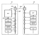
この画像処理システムは、オフィス10とオフィス20とをインターネット104で接続された例を示している。オフィス20内の構成は、オフィス10内と実質的に同じであるので、以下ではオフィス10について説明することとする。
This image processing system shows an example in which an
オフィス10内に構築されたLAN107には、MFP(Multi Function Peripheral:ネットワークスキャナやネットワークプリンタとして機能する複写機)100、MFP100を制御するマネージメントPC101、クライアントPC102、文書ファイルを管理する文書管理サーバ(ファイルサーバ)106、文書データの書式等で検索できるように構成されたデータベース105、およびプロキシサーバ103が接続されている。図示では、クライアントPCが1つだけ示しているが、複数存在し得るものである。
A
オフィス10のネットワーク107はプロキシサーバ13を介してインターネットに接続するようになっている。一方、オフィス20も同様である。従って、オフィス10と20それぞれのネットワークはインターネットを介して相互に情報通信が可能になっている。なお、公知のVPN等の技術でもって第3者がオフィス10、20内のネットワークに侵入することを阻止することが望まれるが、それそのものは本願発明には直接には関係がないので、省略する。
The
さて、実施形態におけるMFP100は、紙文書の画像読み取り部(スキャナー)と読み取った画像信号に対する画像処理の一部(前処理等)を担当し、画像データはLAN109を用いてマネージメントPC101に供給される。マネージメントPCは通常のパーソナルコンピュータで良く、内部に画像記憶手段(ハードディスク)、画像処理手段(画像処理用の回路もしくは画像処理用のプログラム)、表示手段、入力手段(キーボードやマウス(登録商標)等のポインティングデバイス)を有する。
The
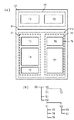
図2はMFP100の構成図である。同図においてオートドキュメントフィーダー(ADF)を含む画像読み取り部110は束状、或いは1枚の原稿画像を図示しない光源で照射し、原稿反射像をレンズで固体撮像素子上に結像し、固体撮像素子からラスター状の画像読み取り信号を例えば600dpiの解像度の画像データを得る。通常の複写を行なう際には、前記画像データをデータ処理部115にて各種補正処理等を行なって記録信号へ変換し、ハードディスク等の記憶装置111に一旦記憶(格納)する。そして、この記憶したことを、マネージメントPC101に通知し、マネージメントPC101の制御の下で記録装置(プリンタエンジン部でもある)112に順次出力して紙上に画像を形成する。
FIG. 2 is a configuration diagram of the
なお、実施形態でのMFPはネットワークプリンタとしても機能するため、ページ記述言語にしたがって印刷イメージデータを生成する機能を有する。ネットワークプリンタとして機能する場合には、クライアントPC102から出力されるプリントデータをLAN107からネットワークIF114を経て、データ処理装置115で記録可能なラスターデータに変換した後、やはり記録装置111に一旦記憶し、マネージメントPC101にそれを通知し、マネージメントPC101の制御の下で記録装置112に順次出力して紙上に画像を形成することになる。このとき、生成したイメージデータが、読取って得たイメージデータであるのか、ネットワークプリンタとして機能した結果生成されたものであるかを示す情報も通知する。
Note that since the MFP in the embodiment also functions as a network printer, it has a function of generating print image data in accordance with a page description language. In the case of functioning as a network printer, the print data output from the client PC 102 is converted from the
113は各種キーやスイッチ、液晶表示画面上に設けられたタッチパネルで構成される入力装置であり、116は液晶表示器である。
An
上記構成において、マネージメントPC101がネットワーク109を介してMFP100と接続する理由は後述する説明から明らかにするが、MFP100内の記憶装置111は、マネージメントPC101からダイレクトにアクセスするようにしており、そのアクセス速度を高速なものとするため、及び、ネットワーク107のトラフィックに影響を与えないためである。
In the above configuration, the reason why the management PC 101 connects to the MFP 100 via the
図3は実施形態におけるマネージメントPC101のブロック構成図である。実施形態におけるマネージメントPC101は、通常のパーソナルコンピュータで実現している。図示において、30は装置全体の制御を司るCPU、31はブートプログラムやBIOSを記憶しているROM、32はCPU30のワークエリアとして使用されるRAMであって、ここにOSをはじめ、実施形態におけるMFP100を管理するプログラムがロードされ実行されることになる。34は表示コントローラであって、ビデオRAMを内蔵している。35は表示装置であって、実施形態では液晶表示装置を採用しているが、CRT等の他の表示装置でも構わない。36は表示装置35のスクリーンの前面に設けられたタッチパネルである。36はMFP100との通信を行うためのネットワークI/F、37はネットワーク107に接続するためのI/Fである。
FIG. 3 is a block diagram of the
通常、パーソナルコンピュータは、キーボード、マウス等(登録商標)のポインティングデバイス等の入力装置を備えるが、本実施形態では、それに代わってタッチパネルが入力装置として機能することになる。キーボードやマウスを備えるものであっても構わないし、それらを併用しても良い。 Usually, a personal computer is provided with an input device such as a keyboard, a mouse (registered trademark) pointing device or the like, but in this embodiment, the touch panel functions as an input device instead. A keyboard and a mouse may be provided, or they may be used in combination.
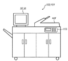
図4は、MFP100にマネージメントPC101を収容した外観図である。図示に示す如く、マネージメントPC101の表示装置35、タッチパネル36が、あたかもMFP100の一部であるかのように見えるようにしている。なお、マネージメントPC101のメンテナンスを行い易くするため、通常のPCが有するキーボードやマウス等のポインティングデバイスを、MFPの筐体内に収容させるようにしても構わない。
FIG. 4 is an external view in which the
また、以下の説明から明らかになるが、マネージメントPC101が有する表示装置35及びタッチパネル36は、実質的にMFP100のユーザインタフェースとして機能する。ならば、MFP100装置内にマネージメントPC101の処理を行う機能を付加させれば良いとも考えられるが、マネージメントPC101の処理は多岐に渡り、その処理を行わせるプログラムの開発、管理の容易性、バージョンアップの容易性の観点から、本実施形態では、複合機であるMFPとは独立した、汎用のパーソナルコンピュータを介在させるようにしている。
As will be apparent from the following description, the
<処理概要の説明>
上記実施形態におけるシステムの処理内容を説明すると次の通りである。
<Description of processing outline>
The processing contents of the system in the above embodiment will be described as follows.
MFP100において、ADFにセットされた原稿は画像読取部110で600dpiの解像度の画像データとして読取られる。読み取られた画像データは、前処理(各種補正処理)を経て、MFP100内の記憶装置111に1ページ分の画像データとして格納される。マネージメントPC101は、MFP100内の記憶装置111に新たなイメージデータが格納されているか否かをネットワーク109を介して監視している。或いは、MFP100が記憶装置111に原稿画像を格納した際にマネージメントPCにネットワーク109を介して通知を受けるようにしても構わない。
In
いずれにしても、マネージメントPC101は、MFP100内の記憶装置111にイメージデータが格納されたと判定すると、以下の処理を行う。
In any case, when the
先ず、読取ったイメージデータを像域分離し、各領域に細分化する(ブロックセグメント化処理)。そして、オリジナルファイルの所在を示すポインタ情報が含まれているか判別を行なう。例えば、予め設定された領域位置に2次元バーコードがあるものとして、2次元バーコードを読取る。2次元バーコードを認識しデコードできた場合、その情報中には読取った原稿に対するオリジナルファイルの所在位置情報(サーバ名+パス付きファイル名)が含まれるので、それをマネジメントPC101の表示装置35に表示する。例えば、
「ファイルサーバ(文書管理サーバ)“xxxxx”の“共有フォルダxxx”内に“xxxxx”として格納されています。」
等のメッセージを表示する。
First, the read image data is divided into image areas and subdivided into areas (block segmentation processing). Then, it is determined whether pointer information indicating the location of the original file is included. For example, the two-dimensional barcode is read on the assumption that there is a two-dimensional barcode at a preset region position. If the two-dimensional bar code can be recognized and decoded, the information includes the location information (server name + file name with path) of the original file for the read document. indicate. For example,
“It is stored as“ xxxx ”in the“ shared folder xxx ”of the file server (document management server)“ xxxx ”.”
Etc. are displayed.
なお、ここでは、ポインタ情報として2次元バーコードを用いたが、それ以外の手法を用いても構わない。例えば、URLを示す文字列オブジェクトを記載しておき、それを文字認識することでポインタ情報を得てもよいし、また、文字と文字の間隔を微小に変化させることによって情報を埋め込む手法や、ハーフトーンの画像に電子透かしとして埋め込む手法等を用いて、ポインタ情報がイメージ内に含まれていても構わない。 Here, a two-dimensional bar code is used as the pointer information, but other methods may be used. For example, a character string object indicating a URL may be described, and pointer information may be obtained by recognizing the character object. Alternatively, a method of embedding information by minutely changing a character-to-character interval, The pointer information may be included in the image by using a method of embedding it as a digital watermark in a halftone image.
また、ユーザがMFP100を複写目的で原稿を読み込ませた場合、マネージメントPC101は、オリジナルファイルを、指定された文書管理サーバより取得し、それに基づいてイメージデータを生成するとともに、生成したイメージデータの所定位置に、オリジナルファイルの所在情報を含んだ2次元バーコードイメージを合成する。そして、その合成したイメージデータを、MFP100内の記憶装置111に格納する。このとき、先に読取って記憶装置111に格納されていたイメージデータは消去、もしくはオリジナルファイルに基づいて生成したイメージデータを、読取ったイメージデータに上書きする。そして、MFP100に対して印刷処理の指示コマンドを送出し印刷処理を行わせる。
When the user causes the
なお、複写目的で原稿を読取ったのか、オリジナルファイルの所在を確認するために読取ったのかの判定は、例えば、MFPが有する操作パネルに設けられたオリジナルの所在確認を行うためのキー及び複写キーのいずれが指示されたのかをMFP100からマネージメントPC101に通知することで行う。また、所在確認するために読取った場合であっても、上記メッセージを表示装置35に表示させた後、タッチパネル36により印刷指示を行うか否かのボタンを表示し、そのボタンのタッチを検出することで印刷を実行する。
Whether the document has been read for the purpose of copying or whether the document has been read to confirm the location of the original file is determined by, for example, a key and a copy key for confirming the original location provided on the operation panel of the MFP. This is performed by notifying which one of the commands is instructed from the
また、複写目的以外に編集目的などにも使用可能である。例えば、MFP100で原稿を読取らせた場合、そのオリジナルファイルを探し出して、その所在を示す情報を表示することになるので、ユーザがネットワークを介してそのオリジナルファイルを、自身が使用するクライアントPCで再度編集することもできるようになる。
It can also be used for editing purposes as well as copying purposes. For example, when the
また、原稿を複写する場合においては、原稿に対応するオリジナルファイルに基づくイメージデータを生成して印刷することになるので、読取り対象の原稿が多少汚れている場合であっても、常に高い品位の画像を複写することができるようになる。 In addition, when copying a document, image data based on the original file corresponding to the document is generated and printed. Therefore, even if the document to be read is somewhat dirty, the image quality is always high. Images can be copied.
一方、MFP100で読取る原稿には、ポインタ情報(2次元バーコード等)が存在しない場合もあり得る。マネジメントPC101は、MFP100内の記憶装置111に格納されたイメージデータ中にバーコードが存在しないと判定する場合である。この場合には、その読取った原稿画像データに近い、既登録済みのオリジナルファイルの中から最も近いファイルを検索する。検索して得られた各候補となったオリジナルデータに基づいてサムネイル画像を生成し、各サムネイル画像とその所在を示す情報をマネジメントPC101が有する表示装置35に一覧表示させ、その中からタッチパネル36で選択することで、該当するオリジナルファイルに基づく画像を印刷できるようにした。なお、ユーザが、そのオリジナルファイルの所在を知っている場合には、明示的にその所在位置及びファイルを指定できるようにしても構わない。
On the other hand, there may be a case where pointer information (such as a two-dimensional barcode) does not exist in a document read by the
さて、原稿画像に対応する候補が1つも存在しない場合、読取った原稿は未登録であると判断し、その旨を表示装置35に表示し、登録する/しないを指示するボタンを表示することで、ユーザに登録の確認を行わせる。
If there is no candidate corresponding to the document image, it is determined that the read document is unregistered, the fact is displayed on the
そして、登録する旨の指示があった場合(「登録」ボタンがタッチされた場合)、それを同じネットワーク上に存在する文書管理サーバ106に、所定形式のデータフォーマットに変換して新規に登録する。そして、登録した際に、その所在が決定されるので、印刷時には、その所在情報を2次元バーコードとして合成して印刷させる。
When there is an instruction to register (when the “Register” button is touched), it is converted into a data format of a predetermined format and newly registered in the
また、オリジナルファイルが見つかった場合でも、そのオリジナルファイルがJPEGやTIFFなどの所謂イメージファイルであった場合、ベクトル化を行なって登録し直すかどうか選択できるようにする。 Even when an original file is found, if the original file is a so-called image file such as JPEG or TIFF, it is possible to select whether to perform vectorization and re-register.
なお、ネットワークプリンタとして機能する場合、上記通知処理は、印刷データを出力してきたクライアントPCに向けて送信し、クライアントPCの画面に表示させることになる。 When functioning as a network printer, the notification process is transmitted to the client PC that has output the print data and displayed on the screen of the client PC.
従って、クライアントPC上で動作するアプリケーションで新規に文書を作成し、印刷した場合、その印刷データには2次元バーコードはないので、上記のように該当するファイルがどれであるのかの選択画面が表示されることになる。そこで、該新規文書が文書管理サーバのデータベースに登録されていなければ、そのユーザは、自身で作成した文書ファイルを文書管理サーバに保存するように指示することになる。 Therefore, when a new document is created and printed by an application that runs on the client PC, there is no two-dimensional barcode in the print data, so the selection screen for the corresponding file as described above is displayed. Will be displayed. Therefore, if the new document is not registered in the database of the document management server, the user instructs the document management server to save the document file created by the user.
<処理内容の詳細>
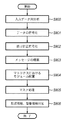
以上が実施形態における概要であるが、以下、図5のフローチャートに従って処理手順(主にマネージメントPC101の処理手順)の詳細を説明することとする。なお、以下では、主に、MFP100で紙文書を読み込んだ場合を説明するが、ネットワークプリンタとして機能する場合の処理は上記の説明及び以下の説明から明らかになるであろう。
<Details of processing contents>
The above is the outline of the embodiment. Hereinafter, the details of the processing procedure (mainly the processing procedure of the management PC 101) will be described according to the flowchart of FIG. In the following, a case where a paper document is read by the
MFP100の画像読み取り部110(ADFを含む)を動作させ1枚の原稿をラスター状に走査し、イメージ情報入力処理120で600dpi(1画素8ビット)の画像信号を得る。該画像信号をデータ処理部115で前処理(補正処理等の変換処理等)を施し記憶装置111に1ページ分の画像データとして保存する。
The image reading unit 110 (including ADF) of the
図5のフローチャートは、このMFP100内の記憶装置111に1ページ分の画像データが記憶された場合にMFP100からの記憶完了の通知、もしくは、MFP100の記憶装置111に1ページ分の画像データが格納したことを検出することで実行されるCPU30の処理手順である。
In the flowchart of FIG. 5, when one page of image data is stored in the
先ず、ステップS40において、記憶装置111に格納された画像データをLAN109を介してRAM32にロードする。次いで、ステップS41で、文字/線画領域とハーフトーンの画像部分とを、矩形領域単位に領域を分離する。文字部分は段落毎に塊としてまとめることによって矩形ブロックに分離し、また、線画部分は線で構成された表、図形毎に分離し、各々セグメント化する。一方、ハーフトーンで表現される画像部分は、矩形に分離されたハーフトーン画像部分、背景部等、所謂、ブロック毎に独立したオブジェクトに分割する。
First, in step S 40, the image data stored in the
ステップS42に処理が進むと、原稿画像中に付加情報として記録されたポインタ情報(2次元バーコード等)を検出し、このバーコードをデコードする。そして、ステップS42において、デコードした情報中にオリジナル電子ファイルが格納されている記憶装置内のポインター情報を検出する(ステップS43)。 When the process proceeds to step S42, pointer information (such as a two-dimensional barcode) recorded as additional information in the document image is detected, and this barcode is decoded. In step S42, pointer information in the storage device in which the original electronic file is stored in the decoded information is detected (step S43).
なお、実施形態では、2次元バーコードによって上記ポインタ情報が表されているものとして説明しているが、2次元バーコードに限らず、原稿画像中の所定位置に、オリジナルファイルの所在を示すURLが記述されている場合でも良い。また、場合によっては、電子透かしという技術で、人間には視認しずらいようにポインタ情報を埋め込むようになっていてもよい。勿論、これら何れでも対処できるようにしてもよい。因に、電子透かしで情報を埋め込む方法には、各文字の間隔を調整して情報を埋め込む手法、ハーフトーン画像中の各画素値を変更することで情報を埋め込む手法などを用いることが可能である。 In the embodiment, the pointer information is described as a two-dimensional barcode. However, the URL is not limited to the two-dimensional barcode, and a URL indicating the location of the original file at a predetermined position in the document image. May be described. In some cases, pointer information may be embedded by a technique called digital watermark so that it is difficult for humans to visually recognize the pointer information. Of course, any of these may be dealt with. Incidentally, as a method of embedding information with a digital watermark, it is possible to use a method of embedding information by adjusting the interval of each character or a method of embedding information by changing each pixel value in a halftone image. is there.
さて、ステップS43では、ポインター情報が検出されたか否かを判定する。ポインタ情報が検出されたと判定した場合には、ステップS45に進んで、そのポインタ情報で示される文書管理サーバ(オフィス10、20のいずれかの文書管理サーバとなる)に該当するファイルが存在するかどうかを判定する。そのファイルの存在が確認できた場合には、ステップS46に進んで、その格納アドレスを表示装置35に表示させると共に、印刷指示ボタン、非印刷指示ボタンを表示する。なお、非印刷指示ボタンの代わりに、編集ボタンや転送ボタンなどを設ける構成としても構わない。
In step S43, it is determined whether pointer information is detected. If it is determined that the pointer information has been detected, the process proceeds to step S45, and whether there is a file corresponding to the document management server (which will be one of the
ステップS47で、非印刷指示ボタンがタッチされたと判断した場合には、本処理を終了する(なお、非印刷指示ボタンの代わりに、編集ボタンや転送ボタンなどを設ける構成としていた場合は、編集や転送などの処理を行う)。また、ステップS47で印刷指示ボタンがタッチされたと判断した場合には、ステップS48に進み、ポインタ情報で示されたオリジナルファイルをロードし、それに基づく印刷イメージデータを生成すると共に、生成されたイメージデータの所定位置に、ポインタ情報を含む2次元バーコードイメージを生成して合成する。そして、その合成した印刷イメージデータを、MFP100内の記憶装置111にLAN109を介して格納する。このとき、原稿を読み取って既に記憶装置111格納されているイメージデータは、削除する。この後、ステップS49に進んで、MFP100のデータ処理部115に対して印刷指示を行う。これを受けて、MFP100内のデータ処理装置115は、記録色成分のデータに変換し(カラープリンタの場合)、記録装置112で印刷を行うことになる。
If it is determined in step S47 that the non-printing instruction button has been touched, this processing is terminated (if the editing button, the transfer button, etc. are provided in place of the non-printing instruction button, editing or Process such as forwarding). If it is determined in step S47 that the print instruction button has been touched, the process proceeds to step S48, where the original file indicated by the pointer information is loaded, print image data based on the original file is generated, and the generated image data A two-dimensional barcode image including pointer information is generated and synthesized at a predetermined position. The combined print image data is stored in the
一方、ステップS44、S45で、ポインタ情報が存在しなかった(2次元バーコードがなかった場合も含む)、或いは、ポインタ情報が検出できたが該当するオリジナルファイルがないと判断した場合、処理はステップS50に進み、先のブロックセグメント化処理で文字領域と判定されたブロック内の文字を認識処理(OCR処理)を行う。そして、ステップS51において、OCRの結果から単語を抽出して全文検索、或いは各オブジェクトのレイアウトと各オブジェクトの属性から所謂レイアウト検索を行う。この検索は、データベース105に対して行う。
On the other hand, if it is determined in steps S44 and S45 that the pointer information does not exist (including the case where there is no two-dimensional barcode) or the pointer information is detected but there is no corresponding original file, the process is as follows. Proceeding to step S50, recognition processing (OCR processing) is performed on the characters in the block determined as the character area in the previous block segmentation processing. In step S51, a word is extracted from the OCR result and a full text search is performed, or a so-called layout search is performed from the layout of each object and the attribute of each object. This search is performed on the
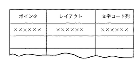
データベース105が管理するデータベースの内容は、例えば図6に示す構造をなしている。図示に示すように、1つのレコードは、ファイルの所在を示すポインタフィールド、1ページを構成するセグメントブロックの位置、個数、属性(文字領域か、線画領域か、ハーフトーン領域かを示す情報)で構成されるレイアウトフィールド、及び、文字領域に含まれる文字コード情報で構成される。
The content of the database managed by the
ステップS51での検索は、読取った1ページの各セグメントブロックの配置位置及び属性情報と、OCRして得た複数の単語を、データベース105に通知し、検索させる。
The search in step S51 notifies the
この検索依頼処理が実行されて類似候補ファイルが検索できた場合、データベース105から検索結果(ポインタ情報とレイアウト情報とする)が通知されるので、ステップS52では、その候補となるレイアウト情報に従って、各候補のサムネイル画像を生成し、サムネイル画像の一覧を表示装置35に表示し、ユーザにその中の1つを選択させる。サムネイル画像はそのサイズが小さいので、文字部分は「・」等で表示し、図形やイメージ部分については、適当な図形、イメージを貼り付けることでサムネイル画像を生成するものとするが、このサムネイル画像はオリジナルファイルを縮小して作成するようにしても構わない。ユーザは、自身が読み込ませた原稿の大方のレイアウトと、表示画面に表示された各候補レイアウトを見比べ、その中の所望とするサムネイル画像をタッチすることで選択することになる。
When this search request process is executed and similar candidate files can be searched, the search result (pointer information and layout information) is notified from the
上述したように、ステップS51で候補が検索されて、ステップS52で候補が選択された場合、処理はステップS53に進み、選択されたサムネイル画像に対応するポインタ情報を用いて、該当するオリジナルファイルを探す。その選択されたオリジナルファイルがJPEGやTIFFやBMP等のベクトル化されていないイメージファイルである場合、先に説明したように、ベクトル化を行なって登録するか否かを問い合わせ、登録する旨の指示があった場合、以下のステップS54乃至S57を行う。一方、選択したサムネイルに対応するオリジナルファイルが、ベクトル化されているファイルであると判断した場合は、ベクトル化するかどうか問い合わせずに、ステップS46に処理を進み、ステップS47以降の処理を行う。 As described above, when a candidate is searched in step S51 and a candidate is selected in step S52, the process proceeds to step S53, and the corresponding original file is selected using the pointer information corresponding to the selected thumbnail image. look for. If the selected original file is a non-vectorized image file such as JPEG, TIFF, BMP, etc., as described above, inquires whether or not to register by vectorization, and an instruction to register If there is, the following steps S54 to S57 are performed. On the other hand, if it is determined that the original file corresponding to the selected thumbnail is a vectorized file, the process proceeds to step S46 without inquiring whether to vectorize or not, and the processes after step S47 are performed.
また、ステップS51での検索の結果、原稿画像に類似するファイルがなかった場合は、ステップS52で類似する画像がなかった旨が通知され、ステップS53でオリジナル電子ファイルなしと判断されてステップS54に進む。 If there is no file similar to the original image as a result of the search in step S51, it is notified in step S52 that there is no similar image. In step S53, it is determined that there is no original electronic file, and the process proceeds to step S54. move on.
なお、ステップS45において、オリジナルファイルがあると判断した場合においても、該オリジナルファイルがJPEGやTIFFなどのベクトル化されていないイメージファイルであった場合、上述したステップS53と同様に、ベクトル化して登録するかどうか問い合わせて、登録する旨の指示が合った場合には、以下のステップS54乃至S57の処理を行なうようにしても良い。 Even if it is determined in step S45 that there is an original file, if the original file is an unvectorized image file such as JPEG or TIFF, it is vectorized and registered in the same manner as in step S53 described above. Inquiries about whether or not to do so, and if an instruction to register is given, the following steps S54 to S57 may be performed.
さて、オリジナルファイルが存在しない場合、あるいは、存在はするがJPEGやBMP等のベクトルコード化されていないイメージファイルであると判断し、更にベクトルコード化して登録する旨の指示を受けた場合には、ステップS54に進んで、予め設定された内容に従って、各セグメントブロックについての後述するベクトル化処理を行う。 When the original file does not exist, or when it is determined that the image file exists but is not vector coded such as JPEG or BMP, and an instruction to register it after vector coding is received. Then, the process proceeds to step S54, and vectorization processing to be described later for each segment block is performed according to the preset contents.
例えば、文字領域であると判定されたセグメントブロックについては、文字イメージの輪郭を識別し、文字イメージの輪郭に沿ったアウトラインベクトルを抽出することによって文字領域をベクトル化する。その際、OCR処理結果は各文字のベクトルデータに対応する文字コードとして保持しておく。 For example, for a segment block determined to be a character region, the character region is vectorized by identifying the contour of the character image and extracting an outline vector along the contour of the character image. At that time, the OCR processing result is held as a character code corresponding to the vector data of each character.
また、前述したような文字イメージの輪郭に基づいてアウトラインベクトルを抽出する処理の代わりに、OCR処理結果で、文字コードを得ているので、原稿画像を忠実に再現するための文字サイズ、スタイル、フォントを識別し、予め文字種別(フォント種別、スタイル)ごとに用意しておいたアウトラインデータを用いて、前記OCR結果の文字コードをベクトル化するようにしても良い。 In addition, instead of the process of extracting the outline vector based on the outline of the character image as described above, the character code is obtained from the OCR process result, so the character size, style, A font is identified, and the character code of the OCR result may be vectorized using outline data prepared for each character type (font type and style) in advance.
また、OCR精度が高い場合は「OCR結果と文字種別毎のアウトラインデータとに基づくベクトル化処理」を実行し、OCRの精度(認識率)が低い場合や、対応するフォントがない場合などにおいては、「文字イメージの輪郭に基づいてアウトラインベクトルを抽出することによるベクトル化処理」を実行するなど、認識率に応じて処理を自動で切り替えるようにしても構わない。 When the OCR accuracy is high, “vectorization processing based on the OCR result and outline data for each character type” is executed, and when the OCR accuracy (recognition rate) is low or there is no corresponding font, etc. The processing may be automatically switched according to the recognition rate, for example, “vectorization processing by extracting outline vector based on outline of character image”.
また、文字種別のアウトラインデータがMFPやクライアントPCに搭載されているのならば、OCR結果の文字コードとその文字サイズ、スタイル、フォントを識別することで、該当するセグメントの書式付テキストデータを作成し、これをベクトル化データとして用いるようにしてもよい。 If outline data of character type is installed in the MFP or client PC, text data with formatting for the corresponding segment is created by identifying the character code of the OCR result and its character size, style, and font. However, this may be used as vectorized data.
これらのいずれの処理手順でベクトル化するかは、予め設定されているものとする。 It is assumed that which processing procedure is used for vectorization is set in advance.
また、図形領域であると判定されたブロックセグメントについては、線画のアウトラインベクトルを抽出することによって、ベクトル化処理を行う。 For the block segment determined to be a graphic region, vectorization processing is performed by extracting the outline vector of the line drawing.
ハーフトーン領域(写真などの自然画像領域)と判定されたセグメントブロックについては、JPEG等の圧縮技術を使う。 For a segment block determined as a halftone area (natural image area such as a photograph), a compression technique such as JPEG is used.
これら各ブロックについての処理内容は、各属性に対する処理設定に従って処理されることになる。また、これらのベクトル化処理はブロック毎に行なわれ、更に、各ブロックのレイアウト情報を保存する。 The processing content for each block is processed according to the processing setting for each attribute. These vectorization processes are performed for each block, and the layout information of each block is stored.
このベクトル化処理後、ステップS55に進んで、レイアウト情報に基づき各ブロックを1つのファイルにまとめ、アプリケーションで編集可能なアプリケーション用データファイルにする。このアプリケーション用データファイルの生成についての詳細は後述するが、例えば、文書中に、イメージデータやベクトルデータをエンベットし、そのエンベットされている文書をrtf(Rich Text Format)形式で保存する。このようにして保存されたrtf形式のファイルを扱うことが可能なアプリケーションで読み込むことで、文章は勿論のこと、図形やイメージデータについても編集できる状態に復元することができる。なお、変換するアプリ用データファイルは、オブジェクト埋め込み可能なrtf形式に限るものではなく、例えば、SVG(Scarable Vector Grafics)フォーマットなどのその他のファイル形式に変換するようにしてもよい。 After this vectorization processing, the process proceeds to step S55, where the blocks are grouped into one file based on the layout information, and the application data file is edited by the application. Although details of generation of the application data file will be described later, for example, image data and vector data are embedded in a document, and the embedded document is stored in an rtf (Rich Text Format) format. By reading an rtf format file saved in this manner with an application that can handle the file, it is possible to restore not only text but also graphics and image data to an editable state. Note that the application data file to be converted is not limited to the rtf format in which the object can be embedded, and may be converted to another file format such as an SVG (Scalable Vector Graphics) format, for example.
処理はステップS56に進むと、マネージメントPC101が接続されているローカルな文書管理サーバ106に登録する。また、ブロックセグメント化処理して得た各セグメントブロックの位置、個数、及び、その属性(文字、図形、ハーフトーンイメージの種別)、更にはOCRして得た文字コード、並びに、文書管理サーバ106に格納した際のポインタ情報と共にデータベース105に登録を行わせる。
In step S56, the processing is registered in the local
この後、ステップS57で、2次元バーコードとして記憶するべきインデックス情報(含むポインタ情報)を生成し、ステップS46に進む。 Thereafter, in step S57, index information (including pointer information) to be stored as a two-dimensional barcode is generated, and the process proceeds to step S46.
ステップS46に進んだ場合には、当該登録した際のファイルの所在が通知されることになる。また、ステップS47で印刷することを指示された場合には、生成したインデックス情報に基づく2次元バーコードを生成し、MFP100の記憶装置111から読出したイメージデータに、生成した2次元バーコードを合成し(ステップS48)、印刷指示を行うことになる。
When the process proceeds to step S46, the location of the file at the time of registration is notified. If printing is instructed in step S47, a two-dimensional barcode based on the generated index information is generated, and the generated two-dimensional barcode is combined with the image data read from the
上記説明では、MFP100に原稿をセットして、読取らせた場合であったが、先に説明したように、実施形態におけるMFP100はネットワークプリンタとしても機能する。従って、クライアントPC102から原稿イメージの印刷データを受信した場合も同様に行われる。すなわち、クライアントPCから印刷データをMFPが受信すると、それによって1ページの原稿イメージを記憶装置111に一旦記憶することに代わりはないからである。ただし、オリジナルファイルの所在の通知は、ネットワーク107を介して、マネージメントPC101がクライアントPCに通知することになる。
In the above description, the document is set on the
さて、以下では、各処理の内容を詳細に説明することとする。 Now, the contents of each process will be described in detail below.
[ブロックセグメント化処理]
ブロックセグメント化処理(ブロックセレクション処理ともいう)とは、図7の右側に示すように、読み取った一頁のイメージデータ(図7の左側)を、各オブジェクト毎の塊として認識し、該ブロック各々を文字/図画/写真/線/表等の属性に判定し、異なる属性を持つ領域に分割する処理である。
[Block segmentation processing]
As shown on the right side of FIG. 7, the block segmentation process (also referred to as block selection process) recognizes the read image data of one page (left side of FIG. 7) as a block for each object, Is attributed to characters / drawings / photos / lines / tables, etc., and is divided into areas having different attributes.
ブロックセグメント化処理の一実施形態を以下に説明する。 One embodiment of the block segmentation process is described below.
先ず、入力画像を白黒に2値化し、輪郭線追跡をおこなって黒画素輪郭で囲まれる画素の塊を抽出する。面積の大きい黒画素の塊については、内部にある白画素に対しても輪郭線追跡をおこない白画素の塊を抽出、さらに一定面積以上の白画素の塊の内部からは再帰的に黒画素の塊を抽出する。 First, the input image is binarized into black and white, and contour tracking is performed to extract a block of pixels surrounded by a black pixel contour. For a black pixel block with a large area, contour tracing is also performed for white pixels inside, and a white pixel block is extracted, and the black pixel block is recursively extracted from the white pixel block with a certain area or more. Extract lumps.
このようにして得られた黒画素の塊を、大きさおよび形状で分類し、異なる属性を持つ領域へ分類していく。たとえば、縦横比が“1”に近く、大きさが一定の範囲のものを文字相当の画素塊とし、さらに近接する文字が整列良くグループ化可能な部分を文字領域、扁平な画素塊を線領域、一定大きさ以上でかつ四角系の白画素塊を整列よく内包する黒画素塊の占める範囲を表領域、不定形の画素塊が散在している領域を写真領域、それ以外の任意形状の画素塊を図画領域、などとする。 The black pixel blocks obtained in this way are classified by size and shape, and are classified into regions having different attributes. For example, if the aspect ratio is close to “1” and the size is within a certain range, it is a pixel block corresponding to a character, a portion where adjacent characters can be grouped in a well-aligned manner is a character region, and a flat pixel block is a line region The area occupied by the black pixel block that is more than a certain size and contains the square white pixel block in a well-aligned manner is the surface area, the area where the irregular pixel block is scattered is the photo area, and any other pixel of any shape A block is defined as a drawing area.
ブロックセグメント化処理で得られた各ブロックに対するブロック情報と、入力画像に含まれるブロックを管理するための入力ファイル情報とを、図8に示す。 FIG. 8 shows block information for each block obtained by the block segmentation process and input file information for managing the blocks included in the input image.
これらのブロック毎の情報は以降に説明するアプリケーションで編集できる形式への変換(以降、この処理をベクトル化という)、或いは検索の為の情報として用いる。 The information for each block is used as information for conversion into a format that can be edited by an application described below (hereinafter, this process is referred to as vectorization) or information for search.
[ポインター情報の検出]
次に、ファイルの格納位置をイメージ情報から抽出する為の処理(ステップS43に対応する処理)について説明する。
[Detection of pointer information]
Next, a process for extracting the file storage position from the image information (a process corresponding to step S43) will be described.
図9は原稿画像中に付加された2次元バーコード(QRコードシンボル)を復号して、データ文字列を出力する過程を示すフローチャートである。2次元バーコードの付加された原稿310の一例を図10に示す。
FIG. 9 is a flowchart showing a process of decoding a two-dimensional barcode (QR code symbol) added to a document image and outputting a data character string. An example of a
まず、MFP100によって、この原稿310を読込むことで、MFP100内のデータ処理装置で各種処理が行われ、記憶装置111にその読取った1枚(1ページ)のイメージデータが格納されると、そのイメージデータをLAN109を介して読出し、イメージデータをCPU30で走査して、先に説明したブロックセグメント化処理の結果から所定の2次元バーコードシンボル311の位置を検出する。QRコードの位置検出パターンは、シンボルの4隅のうちの3隅に配置される同一の位置検出要素パターンから構成されるので、それを検出する(ステップS300)。
First, by reading this original 310 by the
次に、位置検出パターンに隣接する形式情報を復元し、シンボルに適用されている誤り訂正レベルおよびマスクパターンを得る(ステップS301)。 Next, the format information adjacent to the position detection pattern is restored, and the error correction level and mask pattern applied to the symbol are obtained (step S301).
シンボルの型番を決定した(ステップS302)後、形式情報で得られたマスクパターンを使って符号化領域ビットパターンをXOR演算することによってマスク処理を解除する(ステップ303)。尚、モデルに対応する配置規則に従い、シンボルキャラクタを読取り、メッセージのデータ及び誤り訂正コード語を復元する(ステップS304)。 After determining the symbol model number (step S302), the mask process is canceled by performing an XOR operation on the encoded area bit pattern using the mask pattern obtained from the format information (step 303). The symbol character is read according to the arrangement rule corresponding to the model, and the message data and the error correction code word are restored (step S304).
次に、復元されたコード上に、誤りがあるかどうかの検出を行い(ステップS305)、誤りが検出された場合にはステップS306に分岐し、これを訂正する。また、誤り訂正されたデータより、モード指示子および文字数指示子に基づいて、データコード語をセグメントに分割する(ステップS307)。最後に、仕様モードに基づいてデータ文字を復号し、結果を出力する(ステップS308)。 Next, it is detected whether or not there is an error on the restored code (step S305). If an error is detected, the process branches to step S306 to correct it. Further, the data code word is divided into segments based on the mode indicator and the character number indicator from the error-corrected data (step S307). Finally, the data character is decoded based on the specification mode, and the result is output (step S308).
尚、2次元バーコード内に組み込まれたデータは、対応するファイルのアドレス情報(ポインタ情報)を表しており、例えばファイルサーバー名およびファイル名からなるパス情報で構成される。或いは、対応するファイルへのURLで構成される。 The data incorporated in the two-dimensional bar code represents the address information (pointer information) of the corresponding file, and is composed of, for example, path information including a file server name and a file name. Alternatively, it consists of a URL to the corresponding file.
本実施形態ではポインター情報が2次元バーコードを用いて付与された原稿310について説明したが、文字列でポインター情報が記録されるようにしてもよい。その場合は所定のルールに従った文字列のブロック(例えば予め決められた位置にある文字ブロック)を先のブロックセレクション処理で検出し、該ポインター情報を示す文字列の各文字を文字認識する事で、元ファイルのアドレス情報を得る事が可能である。
In the present embodiment, the
また、図10の文書310の文字ブロック312、或いは313の文字列に対して隣接する文字と文字の間隔等に視認し難い程度の微小な変調を加え、該文字間隔に情報を埋め込むことでもポインター情報を付与できる。例えば後述する文字認識処理を行う際に各文字の間隔を検出すれば、ポインター情報が得られる。又、自然画314の中に不可視の電子透かしとしてポインター情報を付加する事も可能である。
Further, the character block 312 of the
[ポインター情報によるファイル検索]
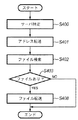
次に、図11を用いて、ポインタ情報に基づくファイル検索処理(ステップS45に対応する処理)について説明する。
[File search by pointer information]
Next, a file search process based on the pointer information (process corresponding to step S45) will be described with reference to FIG.
まず、ポインタ情報に含まれるアドレスに基づいて,ファイル・サーバーを特定する(ステップS400)。 First, the file server is specified based on the address included in the pointer information (step S400).
ここでファイルサーバとは、実施形態では文書管理サーバであることは既に説明したが、場合によってはクライアントPC、或いは、MFP100に画像を蓄積記憶管理する機能を付加するのであれば、MFP100でも構わない。
Here, the file server is already described as a document management server in the embodiment, but may be the
ここでアドレスとは、URLや、サーバ名とファイル名とを含むパス情報である。 Here, the address is URL or path information including a server name and a file name.
ファイルサーバが特定できたら、ファイルサーバに対してアドレスを転送する(ステップS401)。 If the file server can be specified, the address is transferred to the file server (step S401).
ファイルサーバは、アドレスを受信すると、該当するファイルを検索する(ステップS402)。ファイルが存在しない場合(ステップS403の判定がNoの場合)には、マネージメントPCに対してその旨通知する。 Upon receiving the address, the file server searches for the corresponding file (step S402). If the file does not exist (if the determination in step S403 is No), the management PC is notified accordingly.
一方、ファイルが存在した場合(ステップ403の判定がYes)には、先に説明したようにそのファイルを要求元(マネージメントPC)に転送する(ステップS408)。 On the other hand, if the file exists (Yes in step 403), the file is transferred to the request source (management PC) as described above (step S408).
[ファイル検索処理]
次に、ブロックセグメント化で生成された各ブロックの配置位置に基づく検索処理(ステップS51に対応する処理)を図13のフローチャートに従って説明する。すなわち、入力した原稿画像にポインタ情報が存在しなかった場合、または、ポインタ情報は在るが電子ファイルが見つからなかった場合、或いは電子ファイルがイメージファイルであった場合に行われる。
[File search processing]
Next, search processing (processing corresponding to step S51) based on the arrangement position of each block generated by block segmentation will be described with reference to the flowchart of FIG. That is, it is performed when there is no pointer information in the input document image, when there is pointer information but no electronic file is found, or when the electronic file is an image file.
ここでは、セグメントブロック化によって抽出された各ブロックが図8に示す情報(ブロック情報、入力ファイル情報)である場合を説明する。 Here, a case will be described in which each block extracted by segment blocking is information (block information, input file information) shown in FIG.
情報内容として、属性、座標位置、幅と高さのサイズ、OCR情報有無を例としてあげる。属性は、文字、線、写真、絵、表その他に分類する。簡単に説明を行うため、ブロックは座標Xの小さい順に並べる。即ち、図8では、X1<X2<X3<X4<X5<X6であるものとし、各々にブロック1、ブロック2、ブロック3、ブロック4、ブロック5、ブロック6と名前をつけている。ブロック総数は、入力した1ページの画像内に含まれる全ブロック数であり、図8の場合には「6」となる。以下、これらの情報を使用して、データベース内から、入力ファイルに類似したファイルのレイアウト検索を行う処理手順を図13のフローチャートに従って説明する。
Examples of information contents include attributes, coordinate positions, width and height sizes, and presence / absence of OCR information. Attributes are classified into characters, lines, photographs, pictures, tables and others. For simplicity, the blocks are arranged in ascending order of coordinates X. That is, in FIG. 8, it is assumed that X1 <X2 <X3 <X4 <X5 <X6, and the names are
フローチャートの流れは、MFP100で読取りブロックセグメント化処理で得られた上記情報と、データベース105中の同様の種類の情報とを順次比較するものである。
The flow of the flowchart sequentially compares the information obtained by the read block segmentation process in the
まず、ステップS510にて、後述する類似率などの初期化を行う。次に、ステップS511にてブロック総数の比較を行い、ここで、真の場合、さらにファイル内のブロックの情報を順次比較する。ブロックの情報比較では、ステップS513、S515、S518にて、属性類似率、サイズ類似率、OCR類似率をそれぞれ算出し、ステップ522にてそれらをもとに総合類似率を算出する。各類似率の算出方法については、公知の技術が用いることができるので説明を省略する。ステップ523にて総合類似率が、予め設定された閾値Thより高ければステップS524にてそのファイルを類似候補としてあげる。但し、図中のN、W、Hは、入力原稿画像中のブロック総数、各ブロック幅、各ブロック高さとし、ΔN、ΔW、ΔHは、入力ファイルのブロック情報を基準として誤差を考慮したものである。n、w、hは、データベースに格納されているファイルのブロック総数、各ブロック幅、各ブロック高さとする。また、不図示ではあるが、ステップS514にてサイズ比較時に、位置情報X、Yの比較などを行ってもよい。 First, in step S510, initialization such as a similarity rate described later is performed. Next, in step S511, the total number of blocks is compared. If true, the block information in the file is sequentially compared. In block information comparison, an attribute similarity rate, a size similarity rate, and an OCR similarity rate are calculated in steps S513, S515, and S518, respectively, and an overall similarity rate is calculated based on them in step 522. About the calculation method of each similarity rate, since a well-known technique can be used, description is abbreviate | omitted. If the overall similarity is higher than a preset threshold value Th in step 523, the file is listed as a similarity candidate in step S524. In the figure, N, W, and H are the total number of blocks, each block width, and each block height in the input document image, and ΔN, ΔW, and ΔH are based on the block information of the input file and take into account errors. is there. n, w, and h are the total number of blocks of the file stored in the database, each block width, and each block height. Although not shown, the position information X and Y may be compared at the time of size comparison in step S514.
以上、検索処理を、データベース105が有する全データに対して行ない、類似度が閾値Thより高く、候補として保存されたデータベースファイル(ステップS524)をサムネイル等で表示することになる(ステップS52)。複数の中から操作者の選択が必要なら操作者の入力操作よってファイルの特定を行う。
As described above, the search process is performed on all the data included in the
[ベクトル化処理]
次に、イメージデータをベクトル化する処理(ステップS54に対応する処理)について詳説する。
[Vectorization processing]
Next, a process for vectorizing image data (a process corresponding to step S54) will be described in detail.
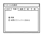
本実施形態では、あらかじめセグメントブロックの種別ごとに処理方法を設定するためのユーザーインターフェースが設けられる。このユーザインターフェースでの設定に応じたベクトル化処理を行う。 In the present embodiment, a user interface for setting a processing method for each segment block type is provided in advance. A vectorization process is performed according to the setting in the user interface.
例えば、文字領域のブロックは、図23のように「ベクトルデータ」、「二値画像」、「多値画像」の排他設定と、「OCR情報付加」のON/OFF設定を行うことができるようにしている。なお、「ベクトルデータ」が選択設定された場合には、ベクトル化を実行する方法として、図23には示していないが、前述したように、「文字イメージの輪郭に基づくベクトル化」や「OCR結果と文字種別毎のアウトラインデータとに基づくベクトル化」や「認識率に応じた処理自動切り替え」などを、更に選択設定できるようにする。 For example, in the block of the character area, as shown in FIG. 23, “vector data”, “binary image”, “multi-valued image” exclusive setting and “OCR information addition” ON / OFF setting can be performed. I have to. When “vector data” is selected and set, as a method for executing vectorization, although not shown in FIG. 23, as described above, “vectorization based on the contour of a character image” or “OCR” “Vectorization based on results and outline data for each character type”, “automatic processing switching according to recognition rate”, and the like can be further selected and set.
線画領域(線で構成される図形等の領域)のブロックや線のブロックは、図24、図25に示すように「ベクトルデータ」、「画像」、「背景オブジェクトに含める」の排他設定できるようにしておく。 As shown in FIG. 24 and FIG. 25, a block of a line drawing area (an area such as a figure composed of lines) or a block of lines can be exclusively set to “vector data”, “image”, and “include in background object”. Keep it.
また、表領域のブロックは、図26に示すように「ベクトルデータ」、「二値画像」、「多値画像」、「背景オブジェクトに含める」の排他設定と、「OCR情報付加」のON/OFF設定を行うことができるようにする。ただし背景オブジェクトに含める場合は、「OCR情報付加」は常にOFFとなる。 In addition, as shown in FIG. 26, the table area block includes exclusive settings of “vector data”, “binary image”, “multivalue image”, and “include in background object”, and ON / OFF of “OCR information addition”. Enable OFF setting. However, when it is included in the background object, “Add OCR information” is always OFF.
更に、写真などの画像領域は、図27に示すように「画像」、「背景オブジェクトに含める」の排他設定できるようにしておく。 Further, an image area such as a photograph can be exclusively set to “image” and “include in background object” as shown in FIG.
なお、これらの設定は、デフォルトでは、文字領域に関して「ベクトルデータ」(輪郭に基づくベクトル化)と「OCR情報付加」が設定され、線画領域及び線領域に関して「ベクトルデータ」が設定され、表領域に関して「ベクトルデータ」と「OCR情報付加」が設定され、写真領域に関して「画像」が設定されているものとする。ユーザから設定変更の指示がなされると、上述の図23〜27に示すようなユーザーインターフェースが呼び出されて設定することができる。また、これらの設定は、ハードディスクなどの電源を切っても保持される不揮発性記憶領域に書き込んでおき、次回以降の起動時にはハードディスクなどから読み出し自動的に設定する。すなわち、一度設定したら、変更しない限りは、従前の設定内容に従って処理される。 In these settings, by default, “vector data” (vectorization based on contour) and “add OCR information” are set for the character area, “vector data” is set for the line drawing area and the line area, and the table area It is assumed that “vector data” and “OCR information addition” are set for “” and “image” is set for the photo area. When a setting change instruction is issued from the user, the user interface as shown in FIGS. 23 to 27 described above can be called and set. These settings are written in a non-volatile storage area that is retained even when the power of the hard disk or the like is turned off, and read from the hard disk or the like at the next and subsequent startups and automatically set. That is, once set, unless changed, processing is performed according to the previous setting contents.
次に、上述のインターフェースを用いて設定された内容に従った処理の詳細を述べる。例えば、文字領域に対して、「二値画像」が設定されていれば、該文字領域を2値化してベクトル化処理の結果とし、「多値画像」が設定されていれば、該文字領域をJPEG等で圧縮してベクトル化処理の結果とする。また、「二値画像」或いは「多値画像」が設定され、且つ、「OCR情報を付加する」がOFFの場合、文字認識結果を付加せず(文字認識処理は行わず)に、画像データのみをベクトル化処理の結果とし、一方、「OCR情報を付加する」がONの場合、『文字認識』処理を行い、認識結果の文字コード、文字の大きさ、位置と、該画像データとをベクトル化結果とする。また、設定が「ベクトルデータ」の場合は、前述したような設定にしたがってベクトル化を行い、「OCR情報を付加する」の設定がONである場合、文字コードと文字のベクトルデータをベクトル化処理の結果とし、OFFの場合は、ベクトルデータのみをベクトル化の結果とする。 Next, details of processing according to the contents set using the above-described interface will be described. For example, if “binary image” is set for a character area, the character area is binarized to obtain the result of vectorization processing. If “multi-valued image” is set, the character area Is compressed as a result of vectorization processing using JPEG or the like. In addition, when “binary image” or “multi-value image” is set and “add OCR information” is OFF, the image data is not added without performing the character recognition result (character recognition processing is not performed). If “add OCR information” is ON, “character recognition” processing is performed, and the character code, character size and position of the recognition result, and the image data are obtained. Let it be a vectorization result. When the setting is “vector data”, vectorization is performed according to the setting as described above. When the setting of “Add OCR information” is ON, the character code and character vector data are vectorized. In the case of OFF, only vector data is used as a result of vectorization.
線画、線領域に対しても同様に設定を読み出し、その設定にしたがって処理する。 The settings are similarly read out for the line drawing and the line area, and processed according to the settings.
例えば、設定が「ベクトルデータ」の場合、そのブロック内の線・線画の輪郭を抽出し、該輪郭に基づいてアウトラインベクトルを生成することによりベクトル化処理を行い、再利用可能なベクトルデータへ変換する。また、設定が「画像」の場合、その領域を一つの画像データとして取り出して圧縮処理等を行い、ベクトル化の結果とする。また、「背景オブジェクトに含める」が設定されている場合、該領域のベクトル化の処理は行わずに、背景オブジェクトの一部として扱う。 For example, when the setting is “vector data”, the outline of the line / line drawing in the block is extracted, and an outline vector is generated based on the outline to perform vectorization processing, which is converted into reusable vector data. To do. When the setting is “image”, the area is extracted as one image data, subjected to compression processing, etc., and the result is vectorized. Further, when “include in background object” is set, the region is handled as part of the background object without performing vectorization processing.
また、表領域に対しても同様に設定を読み出し、その設定にしたがって処理する。 Similarly, the settings for the table area are read out and processed according to the settings.
例えば、「ベクトルデータ」が選択設定されている場合、罫線や文字などの輪郭を抽出して、該輪郭に基づいてアウトラインベクトルを生成することによりベクトル化処理を行う。なお、罫線については「輪郭に基づくベクトル化処理」を行い、文字部分については、前述した文字領域についてのベクトル化処理と同様の処理を行うように設定できるようにしてもよい。また、「OCR情報を付加する」の設定がOnである場合、文字コードとベクトルデータとをベクトル化処理の結果とし、Offの場合は、ベクトルデータのみをベクトル化の結果とする。また、「二値画像」或いは「多値画像」が設定され、且つ、「OCR情報を付加する」がOFFの場合、文字認識結果を付加せず(文字認識処理は行わず)に、該領域の画像データのみをベクトル化処理の結果とし、一方、「OCR情報を付加する」がONの場合、『文字認識』処理を行い、認識結果の文字コード、文字の大きさ、位置と、該画像データとをベクトル化結果とする。また、「背景に含める」の場合は、ベクトル化の処理は行わず背景オブジェクトの一部として扱う。 For example, when “vector data” is selected and set, vectorization processing is performed by extracting outlines such as ruled lines and characters and generating outline vectors based on the outlines. The ruled line may be set to perform “contour-based vectorization processing”, and the character portion may be set to perform the same processing as the above-described vectorization processing for the character region. When the setting of “Add OCR information” is On, the character code and vector data are the results of vectorization processing. When Off is set, only vector data is the result of vectorization. In addition, when “binary image” or “multi-value image” is set and “add OCR information” is OFF, the character recognition result is not added (character recognition processing is not performed), and the region is displayed. When “add OCR information” is ON, “character recognition” processing is performed, and the character code, character size and position of the recognition result, and the image Let the data be the vectorization result. In the case of “include in the background”, the vectorization process is not performed and it is handled as a part of the background object.
また、写真領域に対しても同様に設定を読み出し、その設定にしたがって処理する。例えば、「画像」が選択されている場合、該領域をJPEG等で圧縮する。また、「背景に含める」が選択されている場合は背景オブジェクトの一部として扱う。 Similarly, the setting is read out for the photographic area and processed according to the setting. For example, when “image” is selected, the area is compressed by JPEG or the like. If “include in background” is selected, it is handled as a part of the background object.
[文字認識]
文字認識処理は、文字単位で切り出された画像に対し、パターンマッチの一手法を用いて認識を行い、対応する文字コードを得る。この認識処理は、文字画像から得られる特徴を数十次元の数値列に変換した観測特徴ベクトルと、あらかじめ字種毎に求められている辞書特徴ベクトルと比較し、最も距離の近い字種を認識結果とする処理である。特徴ベクトルの抽出には種々の公知手法があり、たとえば、文字をメッシュ状に分割し、各メッシュ内の文字線を方向別に線素としてカウントしたメッシュ数次元ベクトルを特徴とする方法がある。
[Character recognition]
In the character recognition process, an image cut out in units of characters is recognized using a pattern matching technique, and a corresponding character code is obtained. This recognition process recognizes the character type with the closest distance by comparing the observed feature vector obtained by converting the feature obtained from the character image into a numerical sequence of several tens of dimensions and the dictionary feature vector obtained for each character type in advance. The resulting process. There are various known methods for extracting a feature vector. For example, there is a method characterized by dividing a character into meshes, and using a mesh number-dimensional vector obtained by counting character lines in each mesh as line elements according to directions.
ブロックセグメント化処理で抽出された文字領域に対して文字認識を行う場合は、まず該当領域に対し横書き、縦書きの判定をおこない、各々対応する方向に行を切り出し、その後、文字イメージを切り出す。横書き、縦書きの判定は、該当領域内で画素値に対する水平/垂直の射影を取り、水平射影の分散が大きい場合は横書き領域、垂直射影の分散が大きい場合は縦書き領域と判断すればよい。文字列および文字への分解は、横書きならば水平方向の射影を利用して行を切り出し、さらに切り出された行に対する垂直方向の射影から、文字を切り出すことでおこなう。縦書きの文字領域に対しては、上記水平と垂直の関係を、交換すれば良い。尚、この時、文字のサイズが検出できる。 When character recognition is performed on the character area extracted by the block segmentation process, horizontal writing and vertical writing are first determined for the corresponding area, lines are cut out in the corresponding directions, and then a character image is cut out. Horizontal / vertical writing can be determined by taking a horizontal / vertical projection of the pixel value in the corresponding area, and determining that the horizontal projection area is large when the horizontal projection variance is large, and vertical writing area when the vertical projection variance is large. . For horizontal writing, character strings and characters are decomposed by cutting out lines using horizontal projection, and then cutting out characters from the vertical projection of the cut lines. The vertical and horizontal character areas need only be exchanged. At this time, the character size can be detected.
[フォント認識]
文字認識の際に用いる辞書を、字体数分だけ予め用意しておき、マッチングの際に文字コードと共にフォント種を出力することで文字のフォントが認識できる。つまり、文字認識によって、距離が最も近い特徴ベクトル情報の辞書を特定できれば、それがその文字画像のフォントであると決定する。
[Font recognition]
As many dictionaries as the number of fonts are prepared in advance for character recognition, and font type is output together with the character code at the time of matching, so that the font of the character can be recognized. That is, if the dictionary of feature vector information with the shortest distance can be specified by character recognition, it is determined that this is the font of the character image.
[OCR結果に基づく文字のベクトル化]
前記文字認識およびフォント認識よって得られた、文字コードおよびフォント情報を用いて、文字毎にあらかじめ用意されたアウトラインデータを用いて、文字部分の情報をベクトルデータに変換する。なお、読取った画像の文字がカラーの場合は、各文字の色を抽出してベクトルデータとともに記録する。
[Vectorization of characters based on OCR results]
Using the character code and font information obtained by the character recognition and font recognition, the character portion information is converted into vector data using outline data prepared in advance for each character. If the characters of the read image are color, the color of each character is extracted and recorded together with vector data.
以上の処理により、文字ブロックに属するイメージ情報を、OCR結果に基づいて、ほぼ形状、大きさ、色が忠実なベクトルデータに変換出来る。 Through the above processing, the image information belonging to the character block can be converted into vector data substantially faithful in shape, size, and color based on the OCR result.
[輪郭に基づくベクトル化]
文字領域について文字イメージの輪郭に基づくベクトル化が設定されている場合、あるいは、線画(図画)あるいは線、表領域とされた領域でベクトル化処理を実行すると設定されている場合、以下に記述するように、抽出された画素塊の輪郭に基づいてベクトルデータに変換する。
[Vectorization based on contour]
If vectorization based on the outline of the character image is set for the character area, or if it is set to execute vectorization processing in the area that is a line drawing (drawing), line, or table area, the following is described As described above, the data is converted into vector data based on the contour of the extracted pixel block.
具体的には、輪郭をなす画素の点列を、角と看倣される点で区切って、各区間を部分的な直線あるいは曲線で近似する。角とは曲率が極大となる点であり、曲率が極大となる点は、図14に図示するように、任意点Piに対し左右k個の離れた点Pi-k,Pi+kの間に弦を引いたとき、この弦とPiの距離が極大となる点として求められる。さらに、Pi-k,Pi+k間の弦の長さ/弧の長さをRとし、Rの値が閾値以下である点を角とみなすことができる。角によって分割された後の各区間は、直線は点列に対する最小二乗法など、曲線は3次スプライン関数などを用いてベクトル化することができる。 Specifically, a point sequence of pixels forming an outline is divided by points regarded as corners, and each section is approximated by a partial straight line or curve. The corner is a point where the curvature is maximized, and the point where the curvature is maximized is between k points Pi-k and Pi + k which are separated from the arbitrary point Pi as shown in FIG. When a string is drawn, it is obtained as a point where the distance between this string and Pi becomes a maximum. Further, let R be the chord length / arc length between Pi-k and Pi + k, and the point where the value of R is less than or equal to the threshold value can be regarded as a corner. Each section after being divided by the corners can be vectorized by using a least square method for a straight line and a curve using a cubic spline function.
また、対象が内輪郭を持つ場合、ブロックセレクションで抽出した白画素輪郭の点列を用いて、同様に部分的直線あるいは曲線で近似する。 Further, when the target has an inner contour, it is similarly approximated by a partial straight line or a curve using the point sequence of the white pixel contour extracted by block selection.
以上のように、輪郭の区分線近似を用いれば、任意形状の図形のアウトラインをベクトル化することができる。元原稿がカラーの場合は、カラー画像から図形の色を抽出してベクトルデータとともに記録する。 As described above, the outline of a figure having an arbitrary shape can be vectorized by using the contour line approximation. If the original document is in color, the figure color is extracted from the color image and recorded together with vector data.
図15に示す様に、ある区間で外輪郭と、内輪郭あるいは別の外輪郭が近接している場合、2つの輪郭線をひとまとめにし、太さを持った線として表現することができる。具体的には、ある輪郭の各点Piから別輪郭上で最短距離となる点Qiまで線を引き、各距離PiQiが平均的に一定長を保ってる場合、注目している区間は中点Riを点列として直線あるいは曲線で近似し、その太さは距離PiQiの平均値とする。線や線の集合体である表罫線は、前記のような太さを持つ線の集合として効率よくベクトル表現することができる。 As shown in FIG. 15, when an outer contour and an inner contour or another outer contour are close to each other in a certain section, two contour lines can be combined and expressed as a line having a thickness. Specifically, when a line is drawn from each point Pi of a certain contour to a point Qi that is the shortest distance on another contour, and each distance PiQi keeps a constant length on average, the section of interest is the middle point Ri. Is approximated by a straight line or a curve as a sequence of points, and the thickness is an average value of the distance PiQi. A table ruled line that is a line or a set of lines can be efficiently expressed as a set of lines having the above-described thickness.
[図形認識]
上述したように任意形状の図形のアウトラインをベクトル化した後、これらベクトル化された区分線を図形オブジェクト毎にグループ化する処理について説明する。
[Figure recognition]
A process of grouping the vectorized dividing lines for each graphic object after vectorizing the outline of the figure of an arbitrary shape as described above will be described.
図16は、ベクトルデータを図形オブジェクト毎にグループ化するまでの処理手順を示している。 FIG. 16 shows a processing procedure until vector data is grouped for each graphic object.
まず、各ベクトルデータの始点、終点を算出する(ステップS700)。次に各ベクトルの始点、終点情報を用いて、図形要素を検出する(ステップS701)。図形要素の検出とは、区分線が構成している閉図形を検出することである。検出に際しては、閉形状を構成する各ベクトルはその両端にそれぞれ連結するベクトルを有しているという原理を応用し、検出を行う。次に図形要素内に存在する他の図形要素、もしくは区分線をグループ化し、一つの図形オブジェクトとする(ステップS702)。また、図形要素内に他の図形要素、区分線が存在しない場合は図形要素を図形オブジェクトとする。 First, the start point and end point of each vector data are calculated (step S700). Next, a graphic element is detected using the start point and end point information of each vector (step S701). The detection of a graphic element is to detect a closed graphic formed by a dividing line. In detection, the detection is performed by applying the principle that each vector constituting the closed shape has vectors connected to both ends thereof. Next, other graphic elements or dividing lines existing in the graphic element are grouped into one graphic object (step S702). If there is no other graphic element or dividing line in the graphic element, the graphic element is set as a graphic object.
図17は、図形要素を検出するフローチャートを示している。先ず、ベクトルデータより両端に連結していない不要なベクトルを除去し、閉図形構成ベクトルを抽出する(ステップS710)。次に閉図形構成ベクトルの中から該ベクトルの始点を開始点とし、時計回りに順にベクトルを追っていく。開始点に戻るまで行い、通過したベクトルを全て一つの図形要素を構成する閉図形としてグループ化する(ステップS711)。また、閉図形内部にある閉図形構成ベクトルも全てグループ化する。さらにまだグループ化されていないベクトルの始点を開始点とし、同様の処理を繰り返す。最後に、ステップS710で除去された不要ベクトルのうち、ステップS711で閉図形としてグループ化されたベクトルに接合しているものを検出し一つの図形要素としてグループ化する(ステップS712)。 FIG. 17 shows a flowchart for detecting a graphic element. First, unnecessary vectors not connected to both ends are removed from vector data, and a closed graphic component vector is extracted (step S710). Next, from the closed figure constituent vectors, the starting point of the vector is used as a starting point, and the vectors are sequentially followed in the clockwise direction. The process is repeated until the start point is returned, and all the passed vectors are grouped as a closed graphic constituting one graphic element (step S711). In addition, all closed graphic constituent vectors inside the closed graphic are also grouped. Further, the same processing is repeated with the starting point of a vector not yet grouped as a starting point. Finally, among the unnecessary vectors removed in step S710, those joined to the vector grouped as a closed graphic in step S711 are detected and grouped as one graphic element (step S712).
以上によって図形ブロックを個別に再利用可能な個別の図形オブジェクトとして扱う事が可能になる。 As described above, the graphic block can be handled as an individual graphic object that can be reused individually.
[アプリケーション用データへの変換処理]
ところで、一頁分のイメージデータをブロックセグメント化処し、ベクトル化処理した結果は、中間データ形式のファイルとして変換されている。このような中間データ形式をドキュメント・アナリシス・アウトプット・フォーマット(DAOF)と呼ぶことにする。図18はDAOFのデータ構造を示す図である。
[Conversion to application data]
By the way, the image data for one page is subjected to block segmentation processing, and the result of vectorization processing is converted as an intermediate data format file. Such an intermediate data format will be referred to as a document analysis output format (DAOF). FIG. 18 shows the data structure of DAOF.
図18において、791はHeaderであり、処理対象の文書画像データに関する情報が保持される。レイアウト記述データ部792では、文書画像データ中のTEXT(文字)、TITLE(タイトル)、 CAPTION(キャプション)、LINEART(線画)、PICTURE(自然画)、FRAME(枠)、TABLE(表)等の属性毎に認識された各ブロックの属性情報とその矩形アドレス情報を保持する。文字認識記述データ部793では、TEXT、TITLE、CAPTION等のTEXTブロックを文字認識して得られる文字認識結果を保持する。表記述データ部794では、TABLEブロックの構造の詳細を格納する。画像記述データ部795は、各ブロックのベクトル化処理で生成されたベクトルデータ(画像で保存するように設定されている場合は画像データ)やPICTUREブロックの画像データなどを格納する。
In FIG. 18,
このようなDAOFは、中間データとしてのみならず、それ自体がファイル化されて保存される場合もあるが、このファイルの状態では、所謂、一般の文書作成アプリケーションで個々のオブジェクトを再利用する事は出来ない。そこで、次に、このDAOFからアプリケーション用データに変換する処理について詳説する。 Such a DAOF is not only used as intermediate data, but may be stored as a file itself. In this file state, a so-called general document creation application can reuse individual objects. I can't. Therefore, a process for converting the DAOF into application data will be described in detail.
図19は、全体のこのアプリケーション用データへの概略の処理手順を示している。 FIG. 19 shows a schematic processing procedure for the entire application data.
ステップS8000では、DAOFデータの入力を行う。次いで、ステップS8002は、アプリデータの元となる文書構造ツリー生成を行う。ステップS8004は、文書構造ツリーを元に、DAOF内の実データを流し込み、実際のアプリデータを生成する。 In step S8000, DAOF data is input. In step S8002, a document structure tree that is the source of application data is generated. In step S8004, actual data in the DAOF is flowed based on the document structure tree to generate actual application data.
図20は、ステップS8002の文書構造ツリー生成部の詳細フローチャート、図21(a),(b)は、文書構造ツリーの説明図である。全体制御の基本ルールとして、処理の流れはミクロブロック(単一ブロック)からマクロブロック(ブロックの集合体)へ移行する。図20の説明においてブロックとは、ミクロブロック、及びマクロブロックを指すものとする。 FIG. 20 is a detailed flowchart of the document structure tree generation unit in step S8002, and FIGS. 21A and 21B are explanatory diagrams of the document structure tree. As a basic rule of overall control, the flow of processing shifts from a micro block (single block) to a macro block (an aggregate of blocks). In the description of FIG. 20, the block indicates a micro block and a macro block.
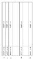
ステップS8100では、ブロック単位で縦方向の関連性を元に再グループ化する。スタート直後はミクロブロック単位での判定となる。ここで、関連性とは、距離が近い、ブロック幅(横方向の場合は高さ)がほぼ同一であることなどで定義することができる。また、距離、幅、高さなどの情報はDAOFを参照し、抽出する。 In step S8100, regrouping is performed on a block basis based on the vertical relationship. Immediately after the start, judgment is made in units of micro blocks. Here, the relevance can be defined by the fact that the distance is close and the block width (height in the horizontal direction) is substantially the same. Information such as distance, width, and height is extracted with reference to DAOF.
図21(a)は実際のページ構成、同図(b)はその文書構造ツリーである。 FIG. 21A shows the actual page configuration, and FIG. 21B shows the document structure tree.
ステップS8100の処理の結果、T3、T4、T5が一つのグループV1として決定され、T6、T7が一つのグループV2として決定され、それぞれが同じ階層のグループとしてまず生成される。 As a result of the processing in step S8100, T3, T4, and T5 are determined as one group V1, T6 and T7 are determined as one group V2, and each is first generated as a group in the same hierarchy.
ステップS8102は、縦方向のセパレータの有無をチェックする。セパレータは、例えば物理的にはDAOF中でライン属性を持つオブジェクトである。また論理的な意味としては、アプリ中で明示的にブロックを分割する要素である。ここでセパレータを検出した場合は、同じ階層で再分割する。 In step S8102, the presence / absence of a vertical separator is checked. For example, the separator is physically an object having a line attribute in the DAOF. Also, logically, it is an element that explicitly divides a block in the application. If a separator is detected here, it is subdivided at the same level.
ステップS8104は、分割がこれ以上存在し得ないか否かをグループ長を利用して判定する。ここで、縦方向のグループ長がページ高さ(該ページに存在する複数のブロックの最上端と最下端の距離)となっている場合は、文書構造ツリー生成は終了する。 In step S8104, it is determined using the group length whether there are no more divisions. Here, when the group length in the vertical direction is the page height (the distance between the uppermost end and the lowermost end of a plurality of blocks existing on the page), the document structure tree generation ends.
図21(a),(b)の場合は、グループV1,V2には、セパレータもなく、グループ高さはページ高さではないので、ステップS8106に進む。 In the case of FIGS. 21A and 21B, the groups V1 and V2 have no separator, and the group height is not the page height, so the process proceeds to step S8106.
ステップS8106は、ブロック単位で横方向の関連性を元に再グループ化する。関連性、及びその判定情報の定義は、縦方向の場合と同じである。 In step S8106, regrouping is performed on a block basis based on the relevance in the horizontal direction. The definition of the relevance and the determination information is the same as in the vertical direction.
図21(a),(b)の場合は、T1,T2でグループH1が生成され、また、V1,V2でグループH2が生成される。グループH1とH2は、V1,V2の1つ上位の同階層のグループとして生成される。 In the case of FIGS. 21A and 21B, a group H1 is generated at T1 and T2, and a group H2 is generated at V1 and V2. Groups H1 and H2 are generated as a group in the same hierarchy one level higher than V1 and V2.
ステップS8108は、横方向セパレータの有無をチェックする。 In step S8108, the presence / absence of a horizontal separator is checked.
図21(a),(b)では、セパレータS1があるので、これをツリーに登録し、H1、S1、H2という階層が生成される。 In FIGS. 21A and 21B, since there is a separator S1, this is registered in the tree, and a hierarchy of H1, S1, and H2 is generated.
ステップS8110は、分割がこれ以上存在し得ないか否かをグループ長を利用して判定する。 In step S8110, it is determined using the group length whether there are no more divisions.
ここで、横方向のグループ長がページ幅(該ページに存在する複数のブロックの最左端と最右端の距離)となっている場合は、文書構造ツリー生成は終了する。そうでない場合は、ステップS8102に戻り、再びもう一段上の階層で、縦方向の関連性チェックから繰り返す。 Here, when the horizontal group length is the page width (the distance between the leftmost end and the rightmost end of a plurality of blocks existing on the page), the document structure tree generation ends. If not, the process returns to step S8102, and the relevance check in the vertical direction is repeated again at the next higher level.
図21(a),(b)の場合は、グループ長がページ幅になっているので、ここで終了し、最後にページ全体を表す最上位階層のV0が文書構造ツリーに付加される。 In the case of FIGS. 21A and 21B, the group length is the page width, so the processing ends here. Finally, V0 in the highest hierarchy representing the entire page is added to the document structure tree.
文書構造ツリーが完成した後、その情報を元にステップS8006においてアプリケーション用データの生成を行う。 After the document structure tree is completed, application data is generated in step S8006 based on the information.
図21(a),(b)の場合の具体例を説明すると以下のようになる。すなわち、H1は水平方向に2つのブロックT1とT2があるので、2カラムとし、T1の内部情報(DAOFを参照、文字認識結果の文章、画像など)を出力後、カラムを変え、T2の内部情報出力、その後、セパレータS1を出力となる。 A specific example in the case of FIGS. 21A and 21B will be described as follows. That is, since there are two blocks T1 and T2 in the horizontal direction, H1 has two columns, and after T1 internal information (refer to DAOF, text of character recognition result, image, etc.) is output, the column is changed and the internal of T2 The information is output, and then the separator S1 is output.
H2は水平方向に2つのブロックV1とV2があるので、2カラムとして出力、V1はT3、T4、T5の順にその内部情報を出力、その後カラムを変え、V2のT6、T7の内部情報を出力する。以上により出力された順番でアプリデータへの変換処理が行えるので、例えば、文字領域の読み順などを正しい順番でアプリデータへ変換できる。 Since H2 has two blocks V1 and V2 in the horizontal direction, it outputs as two columns, V1 outputs its internal information in the order of T3, T4, T5, then changes the column, and outputs the internal information of T6, T7 of V2 To do. Since conversion processing to application data can be performed in the order output as described above, for example, the reading order of character areas can be converted to application data in the correct order.
[ポインター情報の付加]
次に、図5におけるステップS48におけるポインター情報付加処理について説明する。
[Add pointer information]
Next, the pointer information addition process in step S48 in FIG. 5 will be described.
格納されている文書を紙に記録処理する場合、ポインター情報に基づくイメージデータを付加して記録することで、この印刷された文書を再度複写する場合に、簡単に元ファイルデータを取得して、常に高品位な印刷を行うことができる。 When recording a stored document on paper, by adding image data based on pointer information and recording it, when copying this printed document again, the original file data can be easily obtained, High-quality printing can always be performed.
図22はポインター情報としてのデータ文字列を2次元バーコード(QRコードシンボル:JIS X0510)にて符号化(イメージ化)して画像中に付加する過程を示すフローチャートである。 FIG. 22 is a flowchart showing a process of encoding (imaging) a data character string as pointer information with a two-dimensional barcode (QR code symbol: JIS X0510) and adding it to an image.
2次元バーコード内に組み込むデータは、対応するファイルのアドレス情報を表しており、例えばファイルサーバー(文書管理サーバ)名およびファイル名からなるパス情報で構成される。或いは、対応するファイルへのURLや、対応するファイルの格納されているデータベース105内あるいはMFP100自身が有する記憶装置内で管理されるファイルID等で構成されるようにしてもよい。
The data to be incorporated in the two-dimensional barcode represents the address information of the corresponding file, and is composed of, for example, path information including a file server (document management server) name and a file name. Alternatively, it may be configured by a URL to a corresponding file, a file ID managed in the
まず、符号化する種種の異なる文字を識別するため、入力データ列を分析する。また、誤り検出及び誤り訂正レベルを選択し、入力データが収容できる最小型番を選択する (ステップS900)。 First, an input data string is analyzed in order to identify different characters to be encoded. Further, an error detection and error correction level is selected, and a minimum model number that can accommodate input data is selected (step S900).
次に、入力データ列を所定のビット列に変換し、必要に応じてデータのモード(数字、英数字、漢字等)を表す指示子や、終端パターンを付加する。さらに所定のビットコード語に変換する(ステップS901)。 Next, the input data string is converted into a predetermined bit string, and an indicator indicating a data mode (numeric, alphanumeric, kanji, etc.) and a termination pattern are added as necessary. Further, it is converted into a predetermined bit code word (step S901).
この時、誤り訂正を行うため、コード語列を型番および誤り訂正レベルに応じて所定のブロック数に分割し、各ブロック毎に誤り訂正コード語を生成し、データコード語列の後に付加する(ステップS902)。 At this time, in order to perform error correction, the code word string is divided into a predetermined number of blocks according to the model number and the error correction level, an error correction code word is generated for each block, and is added after the data code word string ( Step S902).
該ステップ902で得られた各ブロックのデータコード語を接続し、各ブロックの誤り訂正コード語、必要に応じて剰余コード語を後続する(ステップS903)。 The data code words of the respective blocks obtained in step 902 are connected, and the error correction code word of each block and, if necessary, the remainder code word are followed (step S903).
次に、マトリクスに位置検出パターン、分離パターン、タイミングパターンおよび位置合わせパターン等とともにコード語モジュールを配置する(ステップS904)。 Next, the code word module is arranged in the matrix together with the position detection pattern, separation pattern, timing pattern, alignment pattern, and the like (step S904).
更に、シンボルの符号化領域に対して最適なマスクパターンを選択して、マスク処理パターンをステップS904で得られたモジュールにXOR演算により変換する(ステップS905)。 Further, an optimal mask pattern is selected for the symbol coding region, and the mask processing pattern is converted into a module obtained in step S904 by an XOR operation (step S905).
最後に、ステップS905で得られたモジュールに形式情報および型番情報を生成して、2次元コードシンボルを完成する(ステップS906)。 Finally, format information and model number information are generated in the module obtained in step S905 to complete a two-dimensional code symbol (step S906).
上記に説明した、アドレス情報の組み込まれた2次元バーコードは、例えば、印刷対象の電子ファイルをラスターデータに変換する際に、ラスターデータ上の所定の個所に付加して画像形成する。このようにして画像形成された紙を配布されたユーザーは、画像読取り部110で読み取ることにより、前述したステップ123にてポインター情報からオリジナル電子ファイルの格納場所を検出することができる。
For example, when the electronic file to be printed is converted into raster data, the two-dimensional barcode with address information incorporated therein is added to a predetermined location on the raster data to form an image. The user who has distributed the image-formed paper in this way can detect the storage location of the original electronic file from the pointer information in step 123 described above by reading it with the
尚、同様の目的で付加情報を付与する手段は、本実施形態で説明した2次元バーコードの他に、例えば、ポインター情報を直接文字列で文書に付加する方法、文書内の文字列、特に文字と文字の間隔を変調して情報を埋め込む方法、文書中の中間調画像中に埋め込む方法等、一般に電子透かしと呼ばれる方法が適用出来る。 In addition to the two-dimensional barcode described in this embodiment, the means for adding additional information for the same purpose is, for example, a method of adding pointer information directly to a document as a character string, a character string in a document, A method generally referred to as a digital watermark, such as a method of embedding information by modulating a character spacing and a method of embedding in a halftone image in a document, can be applied.
[ファイルアクセス権に関する別実施形態]
通常、ネットワークを構築し、文書管理サーバで代表されるファイルサーバを設置する場合、第3者による再利用を制限することが行われることが多い。
[Another embodiment regarding file access right]
Usually, when a network is constructed and a file server represented by a document management server is installed, reuse by a third party is often restricted.
先の実施形態では文書管理サーバに蓄積されたファイルは全て自由にアクセスでき、ファイル全体、或いはその一部のオブジェクトは全て再利用が可能な事を前提に説明した。そこで、先の実施形態でポインタ情報からファイルを検索した際に、検索の結果、特定出来たファイルにアクセス権の制限が有る場合についての別実施形態を図12を用いて説明する。同図は、図11に代わるものである。 The previous embodiment has been described on the assumption that all the files stored in the document management server can be freely accessed, and the entire file or a part of its objects can be reused. Therefore, another embodiment of the case in which when the file is searched from the pointer information in the previous embodiment, the access right is restricted for the file identified as a result of the search will be described with reference to FIG. This figure is a substitute for FIG.
ステップS403までは図11の実施形態と同様の為、その説明は省略する。 Steps S403 up to step S403 are the same as those in the embodiment shown in FIG.
ファイルが特定された場合、文書管理サーバはそのファイルのアクセス権情報を調べ、アクセス制限がある場合(ステップS404)には、マネージメントPC101に対してパスワードの送信を要求する。(ステップS405)。マネージメントPC101は、操作者に対してパスワードの入力を促し、入力されたパスワードをファイルサーバに送信する(ステップ406)。なお、実施形態の場合、タッチパネルでの入力となるので、仮想キーボードを表示装置35に表示し、その仮想キーのタッチによって、パスワードを入力する。
When the file is specified, the document management server checks the access right information of the file. If there is an access restriction (step S404), the document management server requests the
文書管理サーバは送信されたパスワードを照合して認証を行い(S407)、認証成功した場合には、図5で説明した様に、ファイルのアドレスを通知すると共に、ユーザの希望する処理が画像ファイルデータの取得であれば、マネジメントPC101に対してファイルを転送する(ステップS408)。尚、アクセス権の制御を行う為の認証の方法は、ステップS405、S406に示したパスワードによる方法に限定されず、例えば、指紋認証等の一般に広く用いられている生体認証、カードによる認証等、全ての認証手段を用いる事が出来る。 The document management server verifies the transmitted password and performs authentication (S407). If the authentication is successful, the file management server notifies the file address as shown in FIG. If the data is to be acquired, the file is transferred to the management PC 101 (step S408). The authentication method for controlling the access right is not limited to the password method shown in steps S405 and S406. For example, generally used biometric authentication such as fingerprint authentication, card authentication, etc. All authentication methods can be used.
又、ここでは、紙文書に付加的に付与されたポインター情報によりファイルを特定した場合の実施形態を示したが、図5のステップS51、S52で示す検索処理でファイルを特定した場合においても同様の制御が可能である。 In addition, here, an embodiment in which a file is specified by pointer information additionally attached to a paper document has been described, but the same applies to a case where a file is specified by the search processing shown in steps S51 and S52 of FIG. Can be controlled.
また、図5のステップS54乃至S56で説明したベクトル化処理に対しても、制限を加える事が出来る。即ち紙文書を走査して得られたイメージ情報から、透かし等により該文書に対してのアクセス権の制限の存在を検出した場合には、認証確認が取れた場合のみベクトル化処理を行う事で、機密性の高い文書の使用に制限をかける事が出来る。 Further, a restriction can be added to the vectorization processing described in steps S54 to S56 of FIG. In other words, when it is detected from image information obtained by scanning a paper document that there is a restriction on the access right to the document using a watermark or the like, the vectorization process is performed only when authentication is confirmed. , You can limit the use of highly confidential documents.
[ファイル特定に関する別実施形態]
先の実施形態では原稿走査して得られるイメージ情報から元ファイルデータを特定する手段は、図5を用いて説明したように、文書中に付与されたポインター情報に基づいて特定するか、或いは文書中に記載された各オブジェクト情報に基づいて対応する電子ファイルを検索するかのいずれかに依るが、より正確に元ファイルを特定するには、該両手段を併用すれば良い。即ち、原稿中から得られるポインター情報から元ファイルの存在が検出出来たとしても、更に該文書中のオブジェクト情報を使って、例えば、レイアウト情報に従うレイアウト検索、文字認識されたキーワードによる全文検索を検出されたファイルに対して行い、高い一致が得られた場合に該検出したファイルを、正式に元ファイルであると特定する。これは、例えば、ポインター情報の下位の部分が曖昧で有ったり、誤り訂正でも訂正できなかった場合に対して、検索の範囲を絞り込んでファイルを特定出来る為、より高速で、確度の高いファイル特定が行える。
[Another embodiment regarding file specification]
In the previous embodiment, as described with reference to FIG. 5, the means for specifying the original file data from the image information obtained by scanning the document is specified based on the pointer information given in the document or the document. Depending on whether the corresponding electronic file is searched based on the object information described therein, both means may be used together in order to specify the original file more accurately. That is, even if the existence of the original file can be detected from the pointer information obtained from the document, the object information in the document is further used to detect, for example, layout search according to the layout information and full-text search using the character-recognized keyword. When a high match is obtained, the detected file is formally specified as the original file. This is because, for example, if the lower part of the pointer information is ambiguous or cannot be corrected by error correction, the file can be specified by narrowing down the search range, so it is faster and more accurate. Can be identified.
[文字領域のベクトル化の別実施例]
文字領域のベクトル化についての別実施例について説明する。
[Another embodiment of vectorization of character area]
Another embodiment of vectorization of character areas will be described.
一つの原稿の処理開始時はベクトルデータが格納されていない辞書を用意する。ある文字ブロックのベクトル化を行う場合、文字ブロックから一文字取り出し文字イメージから特徴抽出を行う。抽出された特徴と辞書とのマッチングを行い、マッチしなかった場合は、文字の特徴抽出結果を辞書に登録し、登録した文字の文字番号を参照する中間データを作成する。マッチする文字が存在すれば辞書内の文字の文字番号を参照する中間データを作成する。中間データは文字の画像内での位置と大きさと、辞書内の何番目の文字とマッチしているか表すもので構成され、例えば図31のような構成である。「x」は文字矩形の左上のX座標値、「y」は文字矩形の左上のY座標値、「w」は文字矩形の幅のピクセル値、「h」は文字矩形の高さのピクセル値、「n」は辞書のn番目の文字とマッチしていることを意味する。一つの文字ブロックの処理が終了すると辞書に登録された文字のイメージに基づいてベクトルデータを生成し、中間データと当該生成された文字ベクトルデータとを合成することでその文字ブロックのベクトル化結果とする。 At the start of processing one document, a dictionary in which vector data is not stored is prepared. When vectorizing a certain character block, one character is extracted from the character block and feature extraction is performed from the character image. The extracted feature and the dictionary are matched. If no match is found, the character feature extraction result is registered in the dictionary, and intermediate data that refers to the character number of the registered character is created. If there is a matching character, intermediate data that refers to the character number of the character in the dictionary is created. The intermediate data is composed of data indicating the position and size of the character in the image, and what number character in the dictionary matches, for example, as shown in FIG. “X” is the X coordinate value at the upper left of the character rectangle, “y” is the Y coordinate value at the upper left of the character rectangle, “w” is the pixel value of the width of the character rectangle, and “h” is the pixel value of the height of the character rectangle. , “N” means that it matches the nth character in the dictionary. When the processing of one character block is completed, vector data is generated based on the character image registered in the dictionary, and the intermediate data and the generated character vector data are combined to generate a vectorization result of the character block. To do.
図30は一つの文字ブロックの処理手順を示すフローチャートである。 FIG. 30 is a flowchart showing the processing procedure of one character block.
処理開始時の辞書の登録文字数をNv、処理中の辞書の登録文字数をNで表すことにすると、開始時はNv=Nである。 If the number of registered characters in the dictionary at the start of processing is represented by Nv and the number of registered characters in the dictionary being processed is represented by N, Nv = N at the start.
ステップS1201の一文字抽出処理では、入力された文字ブロックの画像データから一文字の領域を切り出す処理を行う。ステップS1202では、ステップS1201の結果文字が抽出できたかどうか判断し、抽出できていればステップS1203へ、出来ていなければステップS1208へ処理を進める。 In the single character extraction process in step S1201, a process of cutting out a single character region from the image data of the input character block is performed. In step S1202, it is determined whether or not the result of step S1201 has been extracted. If it has been extracted, the process proceeds to step S1203, and if not, the process proceeds to step S1208.
ステップS1203は、文字の特徴抽出を行う。文字の特徴とは、縦横比、重心位置、輪郭データのヒストグラムベクトルなど(その他の特徴を用いても構わない)である。 Step S1203 performs character feature extraction. Character features include aspect ratio, barycentric position, histogram vector of contour data, etc. (other features may be used).
ステップS1204は、ステップS1203で抽出された文字の特徴と辞書に登録された文字のマッチングを行う。まず辞書の先頭の文字から縦横比と重心位置を比較し大きく異なっている文字は明らかに異なる文字であるため他の情報を使って比較することなく次の辞書中の文字へ比較対象を変更する。縦横比がほぼ等しい場合は、輪郭データのヒストグラムベクトルの比較を行う。ここでは通常のベクトル間の距離を計算し近ければ近いほどマッチングしていることになる。ここで距離があらかじめ決めておいた一定の値以下のものを候補文字としてピックアップしておく。このように辞書内の全ての文字とのマッチングを行う。 In step S1204, the character feature extracted in step S1203 is matched with the character registered in the dictionary. First, compare the aspect ratio and centroid position from the first character of the dictionary, and the characters that are significantly different are clearly different characters, so the comparison target is changed to the next character in the dictionary without using other information for comparison. . When the aspect ratios are almost equal, the histogram vectors of the contour data are compared. Here, the closer the distance between normal vectors is calculated, the closer the match. Here, characters whose distance is equal to or less than a predetermined value are picked up as candidate characters. In this way, matching is performed with all characters in the dictionary.
ステップS1205では、ステップS1204の結果マッチした文字があるかどうか判定し、文字があればステップS1207へ、なければステップS1206へ処理を進める。 In step S1205, it is determined whether there is a matched character as a result of step S1204. If there is a character, the process proceeds to step S1207, and if not, the process proceeds to step S1206.
ステップS1206は、処理中の文字の特徴データを辞書へ登録する。辞書は図32のような形式であり、辞書の最後に追加する。ここでN=N+1として辞書の文字数を1つ増やす処理を行う。中間データIDには図31の何番目の文字に対応するかが格納される。 In step S1206, the feature data of the character being processed is registered in the dictionary. The dictionary has a format as shown in FIG. 32 and is added to the end of the dictionary. Here, N = N + 1 is set to increase the number of characters in the dictionary by one. The intermediate data ID stores what number character in FIG. 31 corresponds to.
ステップS1207では、図31のような形式の、辞書内の対応する文字番号が付与された中間データを生成する。 In step S1207, intermediate data with the corresponding character number in the dictionary in the format as shown in FIG. 31 is generated.
ステップS1208の処理は、文字ブロック内の全ての文字が辞書とのマッチング処理が終了した場合に行われる。開始時はNv文字辞書にあり、終了時がNとなっているため、N−Nv文字分の文字のベクトル化処理を行う。ここでは辞書に格納された文字の文字イメージを少なくとも1つ用いてベクトルデータを生成する。 The process of step S1208 is performed when the matching process of all characters in the character block with the dictionary is completed. Since it is in the Nv character dictionary at the start and N at the end, vectorization processing of characters for N-Nv characters is performed. Here, vector data is generated using at least one character image of characters stored in the dictionary.
ステップS1209は、中間データと辞書に登録されている各文字のベクトルデータを合成する処理を行い、その結果を文字ブロックのベクトル化結果として出力する。 In step S1209, the intermediate data and the vector data of each character registered in the dictionary are combined, and the result is output as the vectorization result of the character block.
このように構成することにより、各文字ブロックごとに同じ文字に対しては同じベクトルデータを使用することができるので、原稿イメージ内の各文字を統一でき、見た目が良くなる。また、原稿内の文字イメージを用いてベクトルデータを生成するので、読み込んだ原稿に忠実なベクトルデータを生成することもできる。 By configuring in this way, the same vector data can be used for the same character in each character block, so that each character in the document image can be unified and the appearance is improved. Further, since vector data is generated using the character image in the original, vector data faithful to the read original can be generated.
[ベクトル化の別実施形態]
先の実施形態では検索手段で、元ファイルの特定が出来ない場合、イメージ画像全体に対してベクトル化処理を行うが、例えば、一般の文書の場合、文書中のオブジェクト全て新規に作成された物でなく、一部のオブジェクトは他のファイルから流用して作成される場合がある。例えば、背景オブジェクト(壁紙)は文書作成アプリケーションで幾つかのパターンを予め用意してあり、その中から選択して用いるのが通常である。従って、このようなオブジェクトは文書ファイルデータベースの中の他の文書ファイル中に存在している可能性が高く、又、再利用可能なベクトルデータとして存在する可能性が高い。
[Another embodiment of vectorization]
In the previous embodiment, when the original file cannot be specified by the search means, the entire image is subjected to vectorization processing. For example, in the case of a general document, all the objects in the document are newly created. Rather, some objects may be created from other files. For example, as a background object (wallpaper), several patterns are prepared in advance by a document creation application, and it is normal to select and use them. Therefore, there is a high possibility that such an object exists in another document file in the document file database, and it is highly likely that the object exists as reusable vector data.
従って、このような背景から、図5のベクトル化処理(ステップS54)の別実施形態として、ブロックセレクション処理で個別のオブジェクトに分割された各オブジェクトに対して、該オブジェクト単位でデータベース中から該一致するオブジェクトを一部に含むファイルを検索し、一致したオブジェクトに対して、個別に該ファイルからオブジェクト単位でベクトルデータを取得する。これに依って、文書全体をベクトル化する必要が無くなり、より高速にベクトル化出来、更に、ベクトル化による画質劣化を防止出来る。 Therefore, from such a background, as another embodiment of the vectorization process (step S54) of FIG. 5, for each object divided into individual objects by the block selection process, the matching is performed from the database for each object. A file including a part of the object to be searched is searched, and the vector data is obtained for each matching object individually from the file. This eliminates the need to vectorize the entire document, enables vectorization at a higher speed, and prevents image quality deterioration due to vectorization.
一方、図5において、検索処理(S51〜S53)で元ファイルがPDFとして特定できた場合、該PDFがその文書の文字オブジェクトに対して既に文字認識された文字コードを付加ファイルとして有している場合がある。このようなPDFファイルをベクトル化する際には、該文字コードファイルを用いれば、S54以降のベクトル化処理の中の文字認識処理を省く事が出来る。即ち、ベクトル化処理をより高速に処理する事が可能に成る。 On the other hand, in FIG. 5, when the original file can be specified as a PDF in the search process (S51 to S53), the PDF has a character code that has already been recognized for the character object of the document as an additional file. There is a case. When vectorizing such a PDF file, if the character code file is used, the character recognition process in the vectorization process after S54 can be omitted. That is, the vectorization process can be performed at a higher speed.
[ベクトル化の別実施形態]
ベクトル化の処理が実行されることになったとき、図28のような現在の設定内容を確認するためのインターフェースを、表示装置35に表示するようにしてもよい。これは、図23から図27で設定されたもので、ハードディスクなどの記憶装置に保存してある設定である。ここで図28の「変換」ボタンをタッチすることで、ベクトル化の処理が起動する。ここで「変更」ボタンをタッチすると、図23から図27のような設定画面が表示され、現在の設定を変更することができる。ただしこの場合の設定の変更はその一回のベクトル化において有効であり、設定の情報はハードディスクには書き込まない。このようにすることにより、ユーザの目的や処理する文書によってベクトル化の処理内容を変更することが可能になる。
[Another embodiment of vectorization]
When the vectorization process is executed, an interface for confirming the current setting contents as shown in FIG. 28 may be displayed on the
また図29のように「デフォルトにする」というボタンを用意することで、変更した設定の内容をハードディスクなどの記憶装置に書き出すことで次回からのベクトル化時に最初に表示される設定を変更できるようになる。このようにすることにより、さらにユーザの目的に応じたベクトル化処理が可能となる。 Also, as shown in FIG. 29, by providing a button “set to default”, the settings that are displayed first at the time of vectorization from the next time can be changed by writing the contents of the changed settings to a storage device such as a hard disk. become. In this way, vectorization processing according to the purpose of the user can be performed.
以上説明したように本実施形態によれば、複写機による紙文書を複写する際に、その文書に対応するオリジナル電子ファイルの所在を確認できると共に、オリジナル電子ファイルに基づく印刷を行うことで、画質劣化のない複写物を得ることができる。 As described above, according to the present embodiment, when a paper document is copied by a copying machine, the location of the original electronic file corresponding to the document can be confirmed, and printing based on the original electronic file can be performed, so that the image quality can be improved. A copy with no deterioration can be obtained.
また、オリジナル電子ファイルが存在しないような紙文書を読取る場合においても、早期の段階でベクトル化処理を実行して登録することで、それ以上の画質劣化を抑制できるようになる。 Further, even when a paper document in which no original electronic file exists is read, further deterioration in image quality can be suppressed by performing vectorization processing and registering at an early stage.
更に、オリジナル電子ファイルが存在しないような紙文書を読取った際の登録処理では、アプリケーションプログラムで再編集できる形式のファイルとして登録する。従って、文書の修正等の作業も簡単なものとすることができる。 Further, in a registration process when a paper document in which no original electronic file exists is read, it is registered as a file in a format that can be re-edited by an application program. Accordingly, it is possible to simplify the work such as document correction.
また、ベクトルデータ化することにより、文書イメージをイメージファイルとして格納する場合に比べ、記憶容量が少なくて済む。 Further, the conversion to vector data requires a smaller storage capacity than when a document image is stored as an image file.
また、ベクトルデータ化することにより、拡大等の画像処理が行なわれたとしても画質劣化を少なくすることができる。 Also, by converting to vector data, image quality degradation can be reduced even if image processing such as enlargement is performed.
また、属性ごとの領域に分割し、属性ごとにベクトル化処理の実行方法を設定できるので、ユーザの目的に適したデータを生成することが可能となる。 Further, since the vectorization processing execution method can be set for each attribute by dividing into regions for each attribute, data suitable for the user's purpose can be generated.
なお、上記実施形態での説明から容易に理解できるように、本実施形態における特徴となる処理の大部分は、汎用の情報処理装置であるマネージメントPC101が実行するコンピュータプログラムによるものであるので、本発明はかかるコンピュータプログラムをもその範疇とするのは明らかである。また、通常、コンピュータで動作するプログラムは、CDROM等のコンピュータ可読記憶媒体をセットし、システムにコピーもしくはインストールすることで実行可能になるものであるから、本発明はかかるコンピュータ可読記憶媒体をもその範疇とするのは明らかである。
As can be easily understood from the description of the above embodiment, most of the processing that is characteristic of the present embodiment is based on a computer program executed by the
以上に説明したように本実施形態によれば、複写対象となった文書のイメージデータから、当該文書に対応するオリジナル文書ファイルを特定し、そのファイルに基づいて印刷することで画質劣化を防ぎ、更に、未登録の文書の場合には登録処理を行うことで、早期の段階で画質劣化を抑制する環境を提供することが可能になる。 As described above, according to the present embodiment, the original document file corresponding to the document is identified from the image data of the document to be copied, and image quality deterioration is prevented by printing based on the file. Furthermore, in the case of an unregistered document, it is possible to provide an environment in which image quality deterioration is suppressed at an early stage by performing registration processing.
Claims (25)
設定手段が、属性毎にベクトル化処理手法を設定させるためのユーザインターフェースを表示装置に表示させ、当該ユーザインターフェースを介して、属性毎のベクトル化処理手法をユーザに設定させる設定ステップと、
検索手段が、入力された文書イメージに基づいて、記憶手段に格納されているオリジナル電子データを検索する検索ステップと、
ベクトル化手段が、前記検索ステップでの検索結果、オリジナル電子データが特定されなかった場合、前記入力された文書イメージに含まれるオブジェクトの属性に基づいて前記文書イメージを複数の領域に分割し、前記設定ステップで属性毎に設定されたベクトル化処理手法にしたがって、当該分割された複数の領域それぞれに対してベクトル化処理を実行するベクトル化ステップと、
格納手段が、前記ベクトル化ステップでベクトルデータ化された該文書イメージのデータをオリジナル電子データとして前記記憶手段に格納する格納ステップと
を有することを特徴とする画像処理装置の制御方法。 A control method for an image processing apparatus for processing an input document image,
A setting step that causes the display device to display a user interface for setting the vectorization processing method for each attribute on the display device, and a setting step for allowing the user to set the vectorization processing method for each attribute via the user interface;
A search step for searching the original electronic data stored in the storage means based on the input document image;
When the original electronic data is not specified as a result of the search in the search step, the vectorization unit divides the document image into a plurality of regions based on the attributes of the object included in the input document image, and according to the set vector processing method for each attribute in the setting step, a vectorization step of executing the vectorized process for each the plurality of divided regions,
A storage means comprising: a storage step of storing the document image data converted into vector data in the vectorization step in the storage means as original electronic data.
属性毎にベクトル化処理手法を設定させるためのユーザインターフェースを表示装置に表示させ、当該ユーザインターフェースを介して、属性毎のベクトル化処理手法をユーザに設定させる設定手段、
入力された文書イメージに基づいて、記憶手段に格納されているオリジナル電子データを検索する検索手段、
前記検索手段での検索結果、オリジナル電子データが特定されなかった場合、前記入力された文書イメージに含まれるオブジェクトの属性に基づいて前記文書イメージを複数の属性毎の領域に分割し、前記設定手段で属性毎に設定されたベクトル化処理手法にしたがって、当該分割された複数の領域それぞれに対してベクトル化処理を実行するベクトル化手段、
前記ベクトル化手段でベクトルデータ化された該文書イメージのデータをオリジナル電子データとして前記記憶手段に格納する格納手段、
として機能させるためのコンピュータプログラム。 The computer,
A setting unit for displaying a user interface for setting a vectorization processing method for each attribute on a display device, and allowing the user to set a vectorization processing method for each attribute via the user interface;
Search means for searching for original electronic data stored in the storage means based on the input document image ;
If the original electronic data is not specified as a result of the search by the search means, the document image is divided into a plurality of attribute areas based on the attributes of the object included in the input document image, and the setting means in accordance with the set vector processing method for each attribute, vectorization means for performing vector processing for each the plurality of divided regions,
Storage means for storing the document image data converted into vector data by the vectorization means in the storage means as original electronic data ;
Computer program to function as.
属性毎にベクトル化処理手法を設定させるためのユーザインターフェースを表示装置に表示させ、当該ユーザインターフェースを介して、属性毎のベクトル化処理手法をユーザに設定させる設定手段、
入力された文書イメージに基づいて、記憶手段に格納されているオリジナル電子データを検索する検索手段、
前記検索手段での検索結果、オリジナル電子データが特定されなかった場合、前記入力された文書イメージに含まれるオブジェクトの属性に基づいて前記文書イメージを複数の属性毎の領域に分割し、前記設定手段で属性毎に設定されたベクトル化処理手法にしたがって、当該分割された複数の領域それぞれに対してベクトル化処理を実行するベクトル化手段、
前記ベクトル化手段でベクトルデータ化された該文書イメージのデータをオリジナル電子データとして前記記憶手段に格納する格納手段、
として機能させるためのコンピュータプログラムを格納した、コンピュータ可読記憶媒体。 The computer,
A setting unit for displaying a user interface for setting a vectorization processing method for each attribute on a display device, and allowing the user to set a vectorization processing method for each attribute via the user interface;
Search means for searching for original electronic data stored in the storage means based on the input document image ;
If the original electronic data is not specified as a result of the search by the search means, the document image is divided into a plurality of attribute areas based on the attributes of the object included in the input document image, and the setting means in accordance with the set vector processing method for each attribute, vectorization means for performing vector processing for each the plurality of divided regions,
Storage means for storing the document image data converted into vector data by the vectorization means in the storage means as original electronic data ;
Storing a computer program for functioning as a computer-readable storage medium.
属性毎にベクトル化処理手法を設定させるためのユーザインターフェースを表示装置に表示させ、当該ユーザインターフェースを介して、属性毎のベクトル化処理手法をユーザに設定させる設定手段と、
入力された文書イメージに基づいて、格納手段に格納されているオリジナル電子データを検索する検索手段と、
前記検索手段での検索結果、オリジナル電子データが特定されなかった場合、前記入力された文書イメージに含まれるオブジェクトの属性に基づいて前記文書イメージを複数の属性毎の領域に分割し、前記設定手段で属性毎に設定されたベクトル化処理手法にしたがって、当該分割された複数の領域それぞれに対してベクトル化処理を実行するベクトル化手段と、
前記ベクトル化手段でベクトルデータ化された該文書イメージのデータをオリジナル電子データとして前記格納手段に格納する格納制御手段と
を有することを特徴とする画像処理システム。 An image processing system for processing a document image,
A setting unit that displays a user interface for setting a vectorization processing method for each attribute on a display device, and allows the user to set a vectorization processing method for each attribute via the user interface;
Search means for searching the original electronic data stored in the storage means based on the input document image;
If the original electronic data is not specified as a result of the search by the search means, the document image is divided into a plurality of attribute areas based on the attributes of the object included in the input document image, and the setting means in accordance with the set vector processing method for each attribute, the vectorization means for executing the vectorized process for each the plurality of divided regions,
An image processing system comprising: storage control means for storing the document image data converted into vector data by the vectorization means in the storage means as original electronic data.
属性毎にベクトル化処理手法を設定させるためのユーザインターフェースを表示装置に表示させ、当該ユーザインターフェースを介して、属性毎のベクトル化処理手法をユーザに設定させる設定手段と、
前記スキャナ搭載装置でスキャンして得た文書イメージに基づいて、格納手段に格納されているオリジナル電子データを検索する検索手段と、
前記検索手段での検索結果、オリジナル電子データが特定されなかった場合、前記入力された文書イメージに含まれるオブジェクトの属性に基づいて前記文書イメージを複数の属性毎の領域に分割し、前記設定手段で属性毎に設定されたベクトル化処理手法にしたがって、当該分割された複数の領域それぞれに対してベクトル化処理を実行するベクトル化手段と、
前記ベクトル化手段でベクトルデータ化された該文書イメージのデータをオリジナル電子データとして前記格納手段に格納する格納制御手段と
を有することを特徴とする情報処理装置。 An information processing device capable of controlling the operation of a scanner-equipped device having at least a scanner,
A setting unit that displays a user interface for setting a vectorization processing method for each attribute on a display device, and allows the user to set a vectorization processing method for each attribute via the user interface;
Search means for searching for original electronic data stored in a storage means based on a document image obtained by scanning with the scanner-equipped device;
If the original electronic data is not specified as a result of the search by the search means, the document image is divided into a plurality of attribute areas based on the attributes of the object included in the input document image, and the setting means in accordance with the set vector processing method for each attribute, the vectorization means for executing the vectorized process for each the plurality of divided regions,
An information processing apparatus comprising: storage control means for storing the document image data converted into vector data by the vectorization means in the storage means as original electronic data.
Priority Applications (4)
| Application Number | Priority Date | Filing Date | Title |
|---|---|---|---|
| JP2003415485A JP4251629B2 (en) | 2003-01-31 | 2003-12-12 | Image processing system, information processing apparatus, control method, computer program, and computer-readable storage medium |
| EP04705520.7A EP1588293B1 (en) | 2003-01-31 | 2004-01-27 | Image processing method, system, program, program storage medium and information processing apparatus |
| US10/536,187 US7664321B2 (en) | 2003-01-31 | 2004-01-27 | Image processing method, system, program, program storage medium and information processing apparatus |
| PCT/JP2004/000710 WO2004068368A1 (en) | 2003-01-31 | 2004-01-27 | Image processing method, system, program, program storage medium and information processing apparatus |
Applications Claiming Priority (3)
| Application Number | Priority Date | Filing Date | Title |
|---|---|---|---|
| JP2003024965 | 2003-01-31 | ||
| JP2003035112 | 2003-02-13 | ||
| JP2003415485A JP4251629B2 (en) | 2003-01-31 | 2003-12-12 | Image processing system, information processing apparatus, control method, computer program, and computer-readable storage medium |
Publications (3)
| Publication Number | Publication Date |
|---|---|
| JP2004265384A JP2004265384A (en) | 2004-09-24 |
| JP2004265384A5 JP2004265384A5 (en) | 2007-02-08 |
| JP4251629B2 true JP4251629B2 (en) | 2009-04-08 |
Family
ID=32830633
Family Applications (1)
| Application Number | Title | Priority Date | Filing Date |
|---|---|---|---|
| JP2003415485A Expired - Fee Related JP4251629B2 (en) | 2003-01-31 | 2003-12-12 | Image processing system, information processing apparatus, control method, computer program, and computer-readable storage medium |
Country Status (4)
| Country | Link |
|---|---|
| US (1) | US7664321B2 (en) |
| EP (1) | EP1588293B1 (en) |
| JP (1) | JP4251629B2 (en) |
| WO (1) | WO2004068368A1 (en) |
Cited By (2)
| Publication number | Priority date | Publication date | Assignee | Title |
|---|---|---|---|---|
| US9049400B2 (en) | 2012-06-06 | 2015-06-02 | Canon Kabushiki Kaisha | Image processing apparatus, and image processing method and program |
| US9277074B2 (en) | 2013-12-04 | 2016-03-01 | Canon Kabushiki Kaisha | Image processing apparatus, method, and medium determining whether image data of a page to be processed is blank and contains a foreground object and transmitting the foreground object obtained by removing a background object |
Families Citing this family (93)
| Publication number | Priority date | Publication date | Assignee | Title |
|---|---|---|---|---|
| JP4181892B2 (en) * | 2003-02-21 | 2008-11-19 | キヤノン株式会社 | Image processing method |
| US7639409B2 (en) * | 2004-01-29 | 2009-12-29 | Bruce Bressler | Scanner with built in mass storage device |
| US8023161B2 (en) * | 2004-02-26 | 2011-09-20 | Sharp Laboratories Of America, Inc. | Systems and methods for providing image data encapsulated in a page description language |
| JP4242796B2 (en) * | 2004-03-12 | 2009-03-25 | パナソニック株式会社 | Image recognition method and image recognition apparatus |
| JP4023480B2 (en) * | 2004-09-08 | 2007-12-19 | コニカミノルタビジネステクノロジーズ株式会社 | Image processing device |
| US8115946B2 (en) * | 2004-10-08 | 2012-02-14 | Sharp Laboratories Of America, Inc. | Methods and sytems for imaging device job definition |
| US8065384B2 (en) | 2004-10-08 | 2011-11-22 | Sharp Laboratories Of America, Inc. | Methods and systems for imaging device event notification subscription |
| US8115947B2 (en) * | 2004-10-08 | 2012-02-14 | Sharp Laboratories Of America, Inc. | Methods and systems for providing remote, descriptor-related data to an imaging device |
| US8120793B2 (en) | 2004-10-08 | 2012-02-21 | Sharp Laboratories Of America, Inc. | Methods and systems for displaying content on an imaging device |
| US20060085430A1 (en) * | 2004-10-08 | 2006-04-20 | Sharp Laboratories Of America, Inc. | Methods and systems for accessing a remote file structure from an imaging device |
| US8006176B2 (en) * | 2004-10-08 | 2011-08-23 | Sharp Laboratories Of America, Inc. | Methods and systems for imaging-device-based form field management |
| US8060921B2 (en) | 2004-10-08 | 2011-11-15 | Sharp Laboratories Of America, Inc. | Methods and systems for imaging device credential authentication and communication |
| US8120798B2 (en) * | 2004-10-08 | 2012-02-21 | Sharp Laboratories Of America, Inc. | Methods and systems for providing access to remote, descriptor-related data at an imaging device |
| US8115945B2 (en) | 2004-10-08 | 2012-02-14 | Sharp Laboratories Of America, Inc. | Methods and systems for imaging device job configuration management |
| US8115944B2 (en) | 2004-10-08 | 2012-02-14 | Sharp Laboratories Of America, Inc. | Methods and systems for local configuration-based imaging device accounting |
| US7920101B2 (en) | 2004-10-08 | 2011-04-05 | Sharp Laboratories Of America, Inc. | Methods and systems for imaging device display standardization |
| US8156424B2 (en) | 2004-10-08 | 2012-04-10 | Sharp Laboratories Of America, Inc. | Methods and systems for imaging device dynamic document creation and organization |
| US8120799B2 (en) * | 2004-10-08 | 2012-02-21 | Sharp Laboratories Of America, Inc. | Methods and systems for accessing remote, descriptor-related data at an imaging device |
| US8237946B2 (en) | 2004-10-08 | 2012-08-07 | Sharp Laboratories Of America, Inc. | Methods and systems for imaging device accounting server redundancy |
| US8384925B2 (en) | 2004-10-08 | 2013-02-26 | Sharp Laboratories Of America, Inc. | Methods and systems for imaging device accounting data management |
| US8230328B2 (en) | 2004-10-08 | 2012-07-24 | Sharp Laboratories Of America, Inc. | Methods and systems for distributing localized display elements to an imaging device |
| US20060077431A1 (en) * | 2004-10-08 | 2006-04-13 | Sharp Laboratories Of America, Inc. | Methods and systems for imaging device concurrent account use |
| US8120797B2 (en) | 2004-10-08 | 2012-02-21 | Sharp Laboratories Of America, Inc. | Methods and systems for transmitting content to an imaging device |
| US8060930B2 (en) * | 2004-10-08 | 2011-11-15 | Sharp Laboratories Of America, Inc. | Methods and systems for imaging device credential receipt and authentication |
| US8213034B2 (en) * | 2004-10-08 | 2012-07-03 | Sharp Laboratories Of America, Inc. | Methods and systems for providing remote file structure access on an imaging device |
| US8125666B2 (en) | 2004-10-08 | 2012-02-28 | Sharp Laboratories Of America, Inc. | Methods and systems for imaging device document management |
| WO2006053023A2 (en) * | 2004-11-09 | 2006-05-18 | Digimarc Corporation | Authenticating identification and security documents |
| JP4502385B2 (en) * | 2004-11-30 | 2010-07-14 | キヤノン株式会社 | Image processing apparatus and control method thereof |
| JP4641414B2 (en) * | 2004-12-07 | 2011-03-02 | キヤノン株式会社 | Document image search apparatus, document image search method, program, and storage medium |
| JP4574347B2 (en) * | 2004-12-28 | 2010-11-04 | キヤノン株式会社 | Image processing apparatus, method, and program |
| US8428484B2 (en) | 2005-03-04 | 2013-04-23 | Sharp Laboratories Of America, Inc. | Methods and systems for peripheral accounting |
| JP4470769B2 (en) * | 2005-03-15 | 2010-06-02 | カシオ計算機株式会社 | Image output apparatus, image output method, and image output program |
| JP4895340B2 (en) * | 2005-03-31 | 2012-03-14 | キヤノン株式会社 | Information processing apparatus and method |
| US7623712B2 (en) | 2005-06-09 | 2009-11-24 | Canon Kabushiki Kaisha | Image processing method and apparatus |
| JP4788205B2 (en) * | 2005-06-22 | 2011-10-05 | 富士ゼロックス株式会社 | Document search apparatus and document search program |
| JP4708888B2 (en) | 2005-07-12 | 2011-06-22 | キヤノン株式会社 | Image processing apparatus, image processing method, and computer program |
| JP4717562B2 (en) * | 2005-09-02 | 2011-07-06 | キヤノン株式会社 | Image processing apparatus and method |
| JP4748789B2 (en) * | 2005-12-05 | 2011-08-17 | キヤノン株式会社 | Image processing method and image processing apparatus |
| US8787660B1 (en) * | 2005-11-23 | 2014-07-22 | Matrox Electronic Systems, Ltd. | System and method for performing automatic font definition |
| JP4799246B2 (en) | 2006-03-30 | 2011-10-26 | キヤノン株式会社 | Image processing method and image processing apparatus |
| JP4764231B2 (en) * | 2006-03-31 | 2011-08-31 | キヤノン株式会社 | Image processing apparatus, control method, and computer program |
| JP4829835B2 (en) | 2006-06-12 | 2011-12-07 | キヤノン株式会社 | Image processing apparatus, image processing method, computer program, and computer-readable storage medium |
| US7961959B2 (en) * | 2006-08-24 | 2011-06-14 | Dell Products L.P. | Methods and apparatus for reducing storage size |
| US7961960B2 (en) * | 2006-08-24 | 2011-06-14 | Dell Products L.P. | Methods and apparatus for reducing storage size |
| US8345272B2 (en) * | 2006-09-28 | 2013-01-01 | Sharp Laboratories Of America, Inc. | Methods and systems for third-party control of remote imaging jobs |
| JP4262276B2 (en) | 2006-12-20 | 2009-05-13 | キヤノン株式会社 | Image processing apparatus, control method therefor, program, and storage medium |
| JP4321604B2 (en) * | 2007-02-20 | 2009-08-26 | ブラザー工業株式会社 | MFP, password setting system and password setting program |
| US8375072B1 (en) * | 2007-04-12 | 2013-02-12 | United Services Automobile Association (Usaa) | Electronic file management hierarchical structure |
| US8396909B1 (en) * | 2007-04-12 | 2013-03-12 | United Services Automobile Association (Usaa) | Electronic file management hierarchical structure |
| JP4402138B2 (en) * | 2007-06-29 | 2010-01-20 | キヤノン株式会社 | Image processing apparatus, image processing method, and computer program |
| JP4590433B2 (en) * | 2007-06-29 | 2010-12-01 | キヤノン株式会社 | Image processing apparatus, image processing method, and computer program |
| US9760839B1 (en) | 2007-07-25 | 2017-09-12 | United Services Automobile Association (Usaa) | Electronic recording statement management |
| JP4956319B2 (en) | 2007-07-30 | 2012-06-20 | キヤノン株式会社 | Image processing apparatus, control method thereof, program thereof, and storage medium |
| JP4952567B2 (en) * | 2007-12-21 | 2012-06-13 | 富士ゼロックス株式会社 | Image search system, image search device, program |
| JP5043715B2 (en) * | 2008-02-22 | 2012-10-10 | キヤノン株式会社 | Image processing device |
| JP4600491B2 (en) * | 2008-02-26 | 2010-12-15 | 富士ゼロックス株式会社 | Image processing apparatus and image processing program |
| JP4626777B2 (en) * | 2008-03-14 | 2011-02-09 | 富士ゼロックス株式会社 | Information processing apparatus and information processing program |
| JP5047051B2 (en) | 2008-05-02 | 2012-10-10 | キヤノン株式会社 | Image processing apparatus and image encoding method |
| JP5111226B2 (en) | 2008-05-02 | 2013-01-09 | キヤノン株式会社 | Image processing method, image processing apparatus, program thereof, and computer-readable storage medium |
| JP5132416B2 (en) * | 2008-05-08 | 2013-01-30 | キヤノン株式会社 | Image processing apparatus and control method thereof |
| JP5028337B2 (en) | 2008-05-30 | 2012-09-19 | キヤノン株式会社 | Image processing apparatus, image processing method, program, and storage medium |
| JP5054618B2 (en) * | 2008-06-10 | 2012-10-24 | 京セラドキュメントソリューションズ株式会社 | Network file processing system |
| JP5302768B2 (en) | 2008-06-26 | 2013-10-02 | キヤノン株式会社 | Image processing apparatus and image processing method |
| JP5219706B2 (en) | 2008-09-12 | 2013-06-26 | キヤノン株式会社 | Image processing apparatus, image processing method, and image processing program |
| JP5028370B2 (en) | 2008-09-19 | 2012-09-19 | キヤノン株式会社 | Image processing apparatus, image processing method, and image processing program |
| JP5178490B2 (en) | 2008-12-17 | 2013-04-10 | キヤノン株式会社 | Image processing apparatus, image processing method, and computer program |
| JP5202281B2 (en) | 2008-12-19 | 2013-06-05 | キヤノン株式会社 | Image processing apparatus and image processing method |
| JP5173898B2 (en) | 2009-03-11 | 2013-04-03 | キヤノン株式会社 | Image processing method, image processing apparatus, and program |
| JP5208043B2 (en) | 2009-04-16 | 2013-06-12 | キヤノン株式会社 | Image processing apparatus, image processing method, and program |
| JP5335581B2 (en) | 2009-07-01 | 2013-11-06 | キヤノン株式会社 | Image processing apparatus, image processing method, and program |
| US20110135144A1 (en) * | 2009-07-01 | 2011-06-09 | Hand Held Products, Inc. | Method and system for collecting voice and image data on a remote device and coverting the combined data |
| JP5550481B2 (en) * | 2009-08-12 | 2014-07-16 | キヤノン株式会社 | Image forming apparatus, image forming method, and program |
| JP5570193B2 (en) * | 2009-12-01 | 2014-08-13 | キヤノン株式会社 | Image management apparatus and image management method |
| JP5528121B2 (en) * | 2010-01-05 | 2014-06-25 | キヤノン株式会社 | Image processing apparatus, image processing method, and program |
| JP2011198246A (en) | 2010-03-23 | 2011-10-06 | Canon Inc | Image processing method, image processing apparatus, program, and program storage medium |
| CN102607409B (en) * | 2011-01-20 | 2016-02-03 | 鸿富锦精密工业(深圳)有限公司 | Image measurement point Lookup protocol and measuring program automatic creation system and method |
| US8665472B2 (en) * | 2011-04-27 | 2014-03-04 | Intellectual Ventures Fund 83 Llc | Producing an image and optical file from a visible first digital image and from a visible second digital image of a machine-readable optical code which encodes information associated with or derived from the first digital image |
| US9721237B2 (en) | 2011-06-24 | 2017-08-01 | Paypal, Inc. | Animated two-dimensional barcode checks |
| CN102890827B (en) * | 2011-10-09 | 2015-05-13 | 北京多看科技有限公司 | Method for resetting scanned document |
| US20130163028A1 (en) * | 2011-12-23 | 2013-06-27 | Udo Klein | Accessing current data by using code images |
| JP5979950B2 (en) | 2012-04-12 | 2016-08-31 | キヤノン株式会社 | Image processing apparatus, control method therefor, and program |
| US9053359B2 (en) * | 2012-06-07 | 2015-06-09 | Konica Minolta Laboratory U.S.A., Inc. | Method and system for document authentication using Krawtchouk decomposition of image patches for image comparison |
| JP5967036B2 (en) * | 2013-08-22 | 2016-08-10 | 富士ゼロックス株式会社 | Image search system, information processing apparatus, and program |
| US9887891B2 (en) | 2015-01-21 | 2018-02-06 | International Business Machines Corporation | Graph segment representing a gist of an online social network conversation |
| JP2017097686A (en) * | 2015-11-26 | 2017-06-01 | キヤノン株式会社 | Information processing unit, control method thereof and program |
| US10572751B2 (en) * | 2017-03-01 | 2020-02-25 | Adobe Inc. | Conversion of mechanical markings on a hardcopy document into machine-encoded annotations |
| US10703112B2 (en) * | 2017-12-13 | 2020-07-07 | Datamax-O'neil Corporation | Image to script converter |
| US10997410B2 (en) * | 2018-08-31 | 2021-05-04 | Ricoh Company, Ltd. | Information processing device and information processing system |
| US20230139849A1 (en) * | 2019-10-17 | 2023-05-04 | Nikon Corporation | Image processing method, image processing device, and image processing program |
| JP2021149439A (en) * | 2020-03-18 | 2021-09-27 | 富士フイルムビジネスイノベーション株式会社 | Information processing apparatus and information processing program |
| CN112668301B (en) * | 2020-10-30 | 2024-06-04 | 生态环境部环境工程评估中心 | Method and system for detecting repeatability of criticizing file |
| CN112417387B (en) * | 2020-11-18 | 2024-07-23 | 国网湖北省电力有限公司信息通信公司 | Dark watermark display and identification device based on computer identification and identification method thereof |
| CN115048915B (en) * | 2022-08-17 | 2022-11-01 | 国网浙江省电力有限公司 | Data processing method and system of electric power file based on operation platform |
Family Cites Families (21)
| Publication number | Priority date | Publication date | Assignee | Title |
|---|---|---|---|---|
| JPH0750483B2 (en) * | 1985-05-22 | 1995-05-31 | 株式会社日立製作所 | How to store additional information about document images |
| CA2039652C (en) * | 1990-05-30 | 1996-12-24 | Frank Zdybel, Jr. | Hardcopy lossless data storage and communications for electronic document processing systems |
| JPH0528258A (en) | 1991-07-19 | 1993-02-05 | Fuji Xerox Co Ltd | Form input device with character/graphic separation device |
| JPH05159062A (en) | 1991-12-09 | 1993-06-25 | Matsushita Electric Ind Co Ltd | Document recognition device |
| JPH06176142A (en) | 1992-12-10 | 1994-06-24 | Meidensha Corp | Outline vectorizing method for automatic drawing input device |
| JP2845107B2 (en) | 1993-10-27 | 1999-01-13 | 三菱電機株式会社 | Image processing device |
| JPH0844827A (en) | 1994-07-27 | 1996-02-16 | Ricoh Co Ltd | Digital copy machine |
| JPH08147445A (en) | 1994-11-16 | 1996-06-07 | Canon Inc | Document managing method and document processor for realizing the same |
| JP3602596B2 (en) | 1995-02-22 | 2004-12-15 | 株式会社東芝 | Document filing apparatus and method |
| US5754308A (en) | 1995-06-27 | 1998-05-19 | Panasonic Technologies, Inc. | System and method for archiving digital versions of documents and for generating quality printed documents therefrom |
| JPH1063820A (en) | 1996-08-26 | 1998-03-06 | Canon Inc | Processor and method for information processing |
| JPH10285378A (en) * | 1997-03-28 | 1998-10-23 | Internatl Business Mach Corp <Ibm> | Copying device and control method therefor |
| JP4071328B2 (en) * | 1997-11-18 | 2008-04-02 | 富士通株式会社 | Document image processing apparatus and method |
| JP2000306103A (en) * | 1999-04-26 | 2000-11-02 | Canon Inc | Method and device for information processing |
| CA2348438C (en) * | 1999-08-30 | 2005-04-26 | Daiwa Can Company | Production method for bottle type can and form-working tool |
| JP2001076095A (en) | 1999-09-06 | 2001-03-23 | Canon Inc | Information processor and method therefor |
| JP2001350763A (en) | 2000-06-07 | 2001-12-21 | Sharp Corp | Device and method for retrieving image and storage medium to be utilized therefor |
| JP4794718B2 (en) | 2000-06-13 | 2011-10-19 | キヤノン株式会社 | Information processing device |
| JP2002298078A (en) | 2001-03-30 | 2002-10-11 | Seiko Epson Corp | Character display, its control method, record medium, and program |
| EP1256900A1 (en) * | 2001-05-09 | 2002-11-13 | Requisite Technology Inc. | Database entry system and method employing optical character recognition |
| JP4895340B2 (en) | 2005-03-31 | 2012-03-14 | キヤノン株式会社 | Information processing apparatus and method |
-
2003
- 2003-12-12 JP JP2003415485A patent/JP4251629B2/en not_active Expired - Fee Related
-
2004
- 2004-01-27 WO PCT/JP2004/000710 patent/WO2004068368A1/en active Application Filing
- 2004-01-27 US US10/536,187 patent/US7664321B2/en not_active Expired - Fee Related
- 2004-01-27 EP EP04705520.7A patent/EP1588293B1/en not_active Expired - Lifetime
Cited By (2)
| Publication number | Priority date | Publication date | Assignee | Title |
|---|---|---|---|---|
| US9049400B2 (en) | 2012-06-06 | 2015-06-02 | Canon Kabushiki Kaisha | Image processing apparatus, and image processing method and program |
| US9277074B2 (en) | 2013-12-04 | 2016-03-01 | Canon Kabushiki Kaisha | Image processing apparatus, method, and medium determining whether image data of a page to be processed is blank and contains a foreground object and transmitting the foreground object obtained by removing a background object |
Also Published As
| Publication number | Publication date |
|---|---|
| EP1588293A4 (en) | 2009-04-01 |
| WO2004068368A1 (en) | 2004-08-12 |
| WO2004068368A8 (en) | 2005-01-20 |
| US7664321B2 (en) | 2010-02-16 |
| EP1588293B1 (en) | 2013-05-22 |
| EP1588293A1 (en) | 2005-10-26 |
| US20060045386A1 (en) | 2006-03-02 |
| WO2004068368A9 (en) | 2005-03-17 |
| JP2004265384A (en) | 2004-09-24 |
Similar Documents
| Publication | Publication Date | Title |
|---|---|---|
| JP4251629B2 (en) | Image processing system, information processing apparatus, control method, computer program, and computer-readable storage medium | |
| US7391917B2 (en) | Image processing method | |
| US7681121B2 (en) | Image processing apparatus, control method therefor, and program | |
| JP4181892B2 (en) | Image processing method | |
| US7640269B2 (en) | Image processing system and image processing method | |
| US8339619B2 (en) | System and image processing method and apparatus for re-using and re-editing images | |
| US7542605B2 (en) | Image processing apparatus, control method therefor, and program | |
| US8520006B2 (en) | Image processing apparatus and method, and program | |
| JP4502385B2 (en) | Image processing apparatus and control method thereof | |
| JP3862694B2 (en) | Image processing apparatus, control method therefor, and program | |
| JP4227432B2 (en) | Image processing method | |
| JP4338189B2 (en) | Image processing system and image processing method | |
| JP2005149097A (en) | Image processing system and image processing method | |
| JP4185858B2 (en) | Image processing apparatus, control method therefor, and program | |
| JP4310176B2 (en) | Image processing apparatus, image processing method, and program | |
| JP2006134042A (en) | Image processing system | |
| JP2005208872A (en) | Image processing system | |
| JP2006146486A (en) | Image processor | |
| JP2006195886A (en) | Image processing system | |
| JP2005157447A (en) | Image processing system and method | |
| JP2005136729A (en) | Device and method for processing image, computer program, and computer-readable recording medium | |
| JP2005165674A (en) | Image processor, image processing method, and computer program | |
| JP2005149098A (en) | Image processing system, image processor and image processing method | |
| JP2006148663A (en) | Image processing system | |
| JP2006134231A (en) | Image processing system |
Legal Events
| Date | Code | Title | Description |
|---|---|---|---|
| A521 | Request for written amendment filed |
Free format text: JAPANESE INTERMEDIATE CODE: A523 Effective date: 20061211 |
|
| A621 | Written request for application examination |
Free format text: JAPANESE INTERMEDIATE CODE: A621 Effective date: 20061211 |
|
| A131 | Notification of reasons for refusal |
Free format text: JAPANESE INTERMEDIATE CODE: A131 Effective date: 20080922 |
|
| A521 | Request for written amendment filed |
Free format text: JAPANESE INTERMEDIATE CODE: A523 Effective date: 20081119 |
|
| TRDD | Decision of grant or rejection written | ||
| A01 | Written decision to grant a patent or to grant a registration (utility model) |
Free format text: JAPANESE INTERMEDIATE CODE: A01 Effective date: 20090116 |
|
| A01 | Written decision to grant a patent or to grant a registration (utility model) |
Free format text: JAPANESE INTERMEDIATE CODE: A01 |
|
| A61 | First payment of annual fees (during grant procedure) |
Free format text: JAPANESE INTERMEDIATE CODE: A61 Effective date: 20090119 |
|
| R150 | Certificate of patent or registration of utility model |
Free format text: JAPANESE INTERMEDIATE CODE: R150 |
|
| FPAY | Renewal fee payment (event date is renewal date of database) |
Free format text: PAYMENT UNTIL: 20120130 Year of fee payment: 3 |
|
| FPAY | Renewal fee payment (event date is renewal date of database) |
Free format text: PAYMENT UNTIL: 20130130 Year of fee payment: 4 |
|
| FPAY | Renewal fee payment (event date is renewal date of database) |
Free format text: PAYMENT UNTIL: 20140130 Year of fee payment: 5 |
|
| LAPS | Cancellation because of no payment of annual fees |