JP4745684B2 - Method for producing polymer blend material - Google Patents
Method for producing polymer blend material Download PDFInfo
- Publication number
- JP4745684B2 JP4745684B2 JP2005053251A JP2005053251A JP4745684B2 JP 4745684 B2 JP4745684 B2 JP 4745684B2 JP 2005053251 A JP2005053251 A JP 2005053251A JP 2005053251 A JP2005053251 A JP 2005053251A JP 4745684 B2 JP4745684 B2 JP 4745684B2
- Authority
- JP
- Japan
- Prior art keywords
- polymer
- screw
- kneading
- cylinder
- blend
- Prior art date
- Legal status (The legal status is an assumption and is not a legal conclusion. Google has not performed a legal analysis and makes no representation as to the accuracy of the status listed.)
- Active
Links
Images


Classifications
-
- B—PERFORMING OPERATIONS; TRANSPORTING
- B29—WORKING OF PLASTICS; WORKING OF SUBSTANCES IN A PLASTIC STATE IN GENERAL
- B29C—SHAPING OR JOINING OF PLASTICS; SHAPING OF MATERIAL IN A PLASTIC STATE, NOT OTHERWISE PROVIDED FOR; AFTER-TREATMENT OF THE SHAPED PRODUCTS, e.g. REPAIRING
- B29C48/00—Extrusion moulding, i.e. expressing the moulding material through a die or nozzle which imparts the desired form; Apparatus therefor
- B29C48/25—Component parts, details or accessories; Auxiliary operations
- B29C48/36—Means for plasticising or homogenising the moulding material or forcing it through the nozzle or die
- B29C48/50—Details of extruders
- B29C48/505—Screws
- B29C48/535—Screws with thread pitch varying along the longitudinal axis
Landscapes
- Engineering & Computer Science (AREA)
- Mechanical Engineering (AREA)
- Compositions Of Macromolecular Compounds (AREA)
- Processes Of Treating Macromolecular Substances (AREA)
- Processing And Handling Of Plastics And Other Materials For Molding In General (AREA)
- Extrusion Moulding Of Plastics Or The Like (AREA)
Description
本発明は、2〜5gの高分子材料を溶融状態で内部帰還型スクリューにより高速回転を行い、せん断成形加工を行うための高分子ブレンド材の製造方法に関するものである。 The present invention relates to a method for producing a polymer blend material for carrying out a shear molding process by rotating 2 to 5 g of a polymer material in a molten state at a high speed with an internal feedback screw.
詳しくは、一方の高分子成分をマトリクスとした場合、他方の高分子成分の分散相サイズを数十ナノメートルサイズに制御した微視的分散構造、あるいは両方の高分子成分が微視的に相互に連続的に繋がった構造(共連続構造)等を有する高分子ブレンドフィルムの製造が可能となる高分子ブレンド材の製造方法を提供するものである。従来、静置場では相互には溶け合わない(非相溶)系のブレンドでも、本発明による高分子ブレンド材の製造方法を用いれば、相容化剤等の余分な添加物を加えることなく、上記構造を実現することが可能となる。さらに詳しくは、例えば、強誘電性材料、コネクターや電子回路基板等の電子・電気用部品、耐熱性構造材料、制振材料、音響材料等の分野で利用される材料として使用できる耐熱性、機械的特性、寸法安定性等に優れたブレンド押出し物を微量試料により試験的に製造するための高分子ブレンド材の製造方法である。 Specifically, when one polymer component is used as a matrix, a microscopic dispersion structure in which the dispersed phase size of the other polymer component is controlled to several tens of nanometers, or both polymer components are microscopically interrelated. The present invention provides a method for producing a polymer blend material that enables the production of a polymer blend film having a structure (co-continuous structure) or the like continuously connected to each other. Conventionally, even in the case of a blend that is incompatible with each other in a stationary field (incompatible), if the method for producing a polymer blend material according to the present invention is used, an extra additive such as a compatibilizer is not added, The above structure can be realized. More specifically, for example, ferroelectric materials, electronic and electrical parts such as connectors and electronic circuit boards, heat resistant structural materials, vibration damping materials, heat resistant materials that can be used as materials used in the field of acoustic materials, machinery This is a method for producing a polymer blend material for experimentally producing a blend extrudate excellent in mechanical properties, dimensional stability, etc., with a small amount of sample.
また、本発明は、容易に1000rpm以上のスクリュー回転が可能な内部帰還型スクリュー搭載のせん断成形加工機を用いて非相溶性高分子ブレンドを溶融混練することにより、一方の高分子成分をマトリクスとした場合、他方の高分子成分の分散相サイズを数十ナノメートルレベルに制御した微視的分散構造を有するナノ分散高分子ブレンド押出し物(フィルムやシート状含む)を製造するものである。 In addition, the present invention melts and kneads an incompatible polymer blend using a shear molding machine equipped with an internal feedback screw capable of easily rotating a screw at 1000 rpm or more, so that one polymer component is used as a matrix. In this case, a nanodispersed polymer blend extrudate (including a film or a sheet) having a microscopically dispersed structure in which the dispersed phase size of the other polymer component is controlled to a level of several tens of nanometers is produced .
従来、静置場では相互に溶け合わない(非相溶性)ブレンド系でも、本発明による手法を用いれば、相容化剤等の余分な添加物を加えることなく、内部帰還型スクリュー搭載のせん断成形加工機を用いて1000rpm以上のスクリュー回転、数分の溶融混練を行うことにより上記構造すなわち数十ナノメーターサイズの分散相を有する高分子ブレンド押出し物を容易に実現することが可能である。さらに詳しくは、例えば、強誘電性材料、圧電性材料、焦電性材料等の電子・電気用部品、耐熱性構造材料、遮音材料、音響材料等の分野で利用される材料として使用できる耐熱性、機械的特性、接着性、運動性等に優れた高分子ブレンド押出し物を製造するものである。 Conventionally, even with blend systems that do not melt together in a stationary field (incompatible), if the method according to the present invention is used, shear molding with an internal feedback screw is added without adding extra additives such as a compatibilizer. A polymer blend extrudate having the above structure, that is, a dispersed phase of several tens of nanometers, can be easily realized by rotating the screw at 1000 rpm or more and performing melt kneading for several minutes using a processing machine . More specifically, for example, heat resistance that can be used as a material used in the fields of electronic and electrical parts such as ferroelectric materials, piezoelectric materials, pyroelectric materials, heat resistant structural materials, sound insulation materials, acoustic materials, etc. , To produce a polymer blend extrudate excellent in mechanical properties, adhesiveness, motility and the like.
従来、非相溶系高分子ブレンド系における分散相のサイズについては、定常剪断流動場中におかれた分散相の最小分散粒子径(D)がニ成分間の界面張力(Γ)、剪断速度(S)、粘度(η)間のバランスによって規定されることがTaylorによって示され、(1)式のように定式化されることが報告されている(非特許文献1(G.I.Taylor, Proc.R.Soc.London, A138,41(1932)、非特許文献2(G.I.Taylor, Proc.R.Soc.London, A146,501(1934) ))。 Conventionally, regarding the size of the dispersed phase in the incompatible polymer blend system, the minimum dispersed particle diameter (D) of the dispersed phase placed in the steady shear flow field is the interfacial tension (Γ) between two components, shear rate ( S) is defined by the balance between the viscosity (η) by Taylor, and it is reported that it is formulated as in equation (1) (Non-Patent Document 1 (GITaylor, Proc. R) Soc. London, A138, 41 (1932), Non-Patent Document 2 (GITaylor, Proc. R. Soc. London, A146, 501 (1934))).

ここに、ηrはニ成分間系の粘度の比、ηmはマトリクス相の粘度である。その後、Wuにより数多くの非相溶系高分子ブレンドに適用され、Dの実測値を再現するため(1)式の改良がなされたが、基本的に関与する物理量は不変である(非特許文献3(S.Wu,Polym.Eng.Sci., 27,335(1987).))。 Here, η r is the ratio of the viscosity of the two-component system, and η m is the viscosity of the matrix phase. After that, although applied to many incompatible polymer blends by Wu and the formula (1) was improved in order to reproduce the measured value of D, the physical quantity involved is basically unchanged (Non-patent Document 3). (S. Wu, Polym. Eng. Sci., 27, 335 (1987))).
例えば、リアクティブプロセシング技術は、界面で共重合体が生成することにより界面張力を低下させるので、(1)式により、分散相の粒子径が小さくなることが理解できる。このような定式化により、非相溶系高分子ブレンド系における分散相サイズの理論的限界もMacosko等(U.Sundararaj and C.W.Macosko, Macromolecules, 28,2647,(1995).)(非特許文献4)により、図1のように示されたが、ここでは定常剪断速度(S)が、通常の混練押出機で発生し得る範囲(S=10〜80sec-1)に限定されている。即ち、(1)式を再考すると、Dの理論限界は、剪断速度と粘度とのバランスにもよるが、より高い剪断速度域の利用が分散相サイズの減少に寄与することが容易に推察される。事実、静置場では、非相溶な高分子ブレンド系が高剪断場下では相溶することが最近、報告されている。例えば、ポリ(p−フェニレンスルフィド)とナイロン46系で、剪断流動場下(S=189sec-1)においてナイロンリッチ側の領域でのみ相溶化することが報告された(非特許文献5(J-B An, T.Suzuki, T.Ougizawa, T.Inoue, K.Mitamura, and K.Kawanishi, J.Macromol.Sci.,-Physics, B41,407(2002).))。 For example, the reactive processing technique lowers the interfacial tension due to the formation of a copolymer at the interface, so that it can be understood from the equation (1) that the particle size of the dispersed phase is reduced. By such a formulation, the theoretical limit of the disperse phase size in the incompatible polymer blend system is also determined by Macosko et al. (U. Sundararaj and CW Macosko, Macromolecules, 28, 2647, (1995)) (Non-patent Document 4). 1, the steady shear rate (S) is limited to a range (S = 10 to 80 sec −1 ) that can be generated by a normal kneading extruder. That is, when formula (1) is reconsidered, the theoretical limit of D depends on the balance between the shear rate and the viscosity, but it is easily assumed that the use of a higher shear rate region contributes to the reduction of the dispersed phase size. The In fact, it has recently been reported that incompatible fields, incompatible polymer blend systems are compatible under high shear conditions. For example, it has been reported that poly (p-phenylene sulfide) and nylon 46 system are compatibilized only in the region on the nylon rich side under a shear flow field (S = 189 sec −1 ) (Non-Patent Document 5 (JB An , T. Suzuki, T. Ougizawa, T. Inoue, K. Mitamura, and K. Kawanishi, J. Macromol. Sci., -Physics, B41, 407 (2002).)).
従って、従来は所望のブレンド物の性能をある程度発現させるために、ブレンド成分の一方もしくは両方と親和性もしくは接着性のある相容化剤を用いてブレンド化を行っていたが、本質的に分子レベルで相互に溶解していないために、それらの性能や機能を極限まで高めることはできなかった。また、30年前に発見されたリアクティブプロセシング技術(非特許文献6(F.Ide and A.Hasegawa, J.Appl.Polym.Sci., 18,963(1974).))は上述したように界面張力を低下させて、分散相サイズを小さくすることが予想されるが、ニ成分間に反応性基が存在しないと実現しないという欠点が存在する。従って、相容化剤等の余分な添加物を使用せずに、非相溶系高分子ブレンド系を相溶化させるには、高剪断領域でのブレンドの混合技術、即ち高剪断成形加工が必要である。実際には、スクリュー構造等にも依存するため、成形加工機におけるスクリュー回転数と剪断速度との対応は一義的には決まらないが、通常の成形加工機におけるスクリュー回転数は100〜300rpmであり、対応する剪断速度が高々100sec-1前後と見積もられることから、まずスクリュー回転数を大幅に高速化(500rpm以上)することが剪断速度の飛躍的な増大に結びつくものと考えられる。 Therefore, in the past, in order to express the performance of the desired blend to some extent, blending was performed using a compatibilizing agent having affinity or adhesion with one or both of the blend components. Because they are not mutually soluble at the level, their performance and function could not be enhanced to the limit. Reactive processing technology discovered 30 years ago (Non-Patent Document 6 (F. Ide and A. Hasegawa, J. Appl. Polym. Sci., 18,963 (1974).)) Is expected to reduce the size of the dispersed phase, but there is a drawback that it cannot be realized if there is no reactive group between the two components. Therefore, in order to compatibilize an incompatible polymer blend system without using an extra additive such as a compatibilizer, a blending technique in a high shear region, that is, a high shear molding process is required. is there. Actually, depending on the screw structure, etc., the correspondence between the screw rotation speed and the shear rate in the molding machine is not uniquely determined, but the screw rotation speed in a normal molding machine is 100 to 300 rpm. Since the corresponding shear rate is estimated to be around 100 sec −1 at the most, it is considered that a significant increase in the screw rotation speed (500 rpm or more) first leads to a dramatic increase in the shear rate.
従来、通常の混練押出し機(スクリュー回転数300rpm程度)を用いて非相溶性高分子ブレンド系の単純機械的混合を行った場合、一方の高分子成分の分散相サイズにおける理論的・実験的限界はMacosko等により、350ナノメーター(nm)であると非特許文献4に報告されている。従って、所望の高分子ブレンド物の性能や機能を相乗効果として発現させるために、従来、ブレンド成分の一方もしくは両方と親和性もしくは接着性のある相容化剤を用いて混練を行っていたが、本質的に分子レベルで相互に溶解していないために、一方の高分子成分をマトリクスとした場合、他方の高分子成分の分散相サイズが数ミクロン〜サブミクロンメーターレベルとなる高分子ブレンド押出し物しか得られず、それらの性能や機能を極限まで高めることはできなかった。また、30年前に発見されたリアクティブプロセシング技術(非特許文献6)はブレンド成分間に存在する官能基間で反応を起こすことにより界面張力を低下させて、分散相サイズを小さくする手法であり、高分子ブレンド系の分散相サイズをサブミクロンメーター〜数十ナノメーターレベルにまで低減化することに成功しているが、ニ成分間に反応性基が存在しないと実現しないため技術的に大きな障害となっている。 Conventionally, when simple mechanical mixing of an incompatible polymer blend system is performed using a normal kneading extruder (screw rotation speed of about 300 rpm), the theoretical and experimental limits on the dispersed phase size of one polymer component Is reported in Non-Patent Document 4 as 350 nanometers (nm) by Macosko et al. Therefore, in order to express the performance and function of a desired polymer blend as a synergistic effect, conventionally, kneading has been performed using a compatibilizer having affinity or adhesiveness with one or both of the blend components. Because of the fact that they are not essentially dissolved in each other at the molecular level, when one polymer component is used as a matrix, the polymer phase is extruded with the dispersed phase size of the other polymer component being on the order of several microns to submicrometers. Only the thing was obtained, and those performance and functions could not be enhanced to the limit. In addition, reactive processing technology (Non-Patent Document 6) discovered 30 years ago is a technique that reduces the interfacial tension by causing a reaction between functional groups existing between blend components, thereby reducing the size of the dispersed phase. Yes, we have succeeded in reducing the dispersed phase size of polymer blends to sub-micrometer to tens of nanometer level, but technically because there is no reactive group between the two components. It has become a major obstacle.
従って、非相溶性高分子ブレンド系の性能、機能の相乗効果の発現を目指してブレンド化を図る場合は、分子レベルに近いサイズで分散相を制御する必要があり、従来技術の延長では容易にナノ分散高分子ブレンド物を作製することが困難であった。また、相容化剤等添加物の混入やリアクティブプロセシング法により生じた反応生成物等は、連続的かつ純粋な微細構造を必要とする光学材料や電子・電気材料においては構造上の“欠陥もしくは異物”となってしまうので、実用上大きな障害となってしまう欠点があった。 Therefore, when blending with the aim of expressing the synergistic effect of the incompatible polymer blend system, it is necessary to control the dispersed phase at a size close to the molecular level. It was difficult to produce a nano-dispersed polymer blend. In addition, admixtures of additives such as compatibilizers and reaction products generated by reactive processing methods are structural defects in optical materials and electronic / electrical materials that require a continuous and pure microstructure. In other words, it is a “foreign substance”, which has a drawback that it becomes a large obstacle in practical use.
このような背景の元に、発明者は1000rpm以上のスクリュー回転が可能(最高出力3000rpm)な内部帰還型スクリュー搭載の微量型高剪断成形加工機を発明し製作した。当該装置は『微量型高せん断成形加工機HSE3000mini』という名称ですでに市販されている。本発明は当該微量型高剪断成形加工機を用いることにより初めて実現することができる。
Against this background, the inventor has invented and manufactured a micro-high shear molding machine equipped with an internal feedback screw that can rotate a screw at 1000 rpm or more (
本発明の課題は、従来、静置場では相互に溶け合わない(非相溶)系のブレンドに対して、相容化剤等の余分な添加物を加えることなく、高剪断領域でブレンドを溶融混練することにより、相互に分子レベルで溶解した(相溶)構造、一方の高分子成分をマトリクスとした場合、他方の高分子成分の分散相サイズを数十ナノメートルサイズに制御した微視的分散構造、あるいは両方の高分子成分が微視的に相互に連続的に繋がった構造(共連続構造)等を有する高分子ブレンドフィルムを製造するための装置を提供することである。 The object of the present invention is to melt the blend in a high shear region without adding an extra additive such as a compatibilizing agent to a blend that has not been incompatible with each other in a static place (incompatible). A structure in which the components are dissolved at the molecular level by kneading. When one polymer component is used as a matrix, the dispersed phase size of the other polymer component is controlled to a size of several tens of nanometers. An object of the present invention is to provide an apparatus for producing a polymer blend film having a dispersed structure or a structure (co-continuous structure) in which both polymer components are continuously connected microscopically.
発明者の1人は、静置場では相互に溶け合わない(非相溶)系のブレンドが高剪断流動場下では相溶する領域が存在することを見出し、その基礎的データを報告している(非特許文献7(H.Shimizu, K.Komori, and T.Inoue, Transactions of the Materials Research Society of Japan, 29, 263(2004).))。そこで、発明者等は、この高剪断領域での基礎的知見を成形加工条件として活かすには、高剪断流動場を発生し得る、即ち、スクリューの高速回転が可能な成形加工機を製造する必要があることに気づいた。 One of the inventors found that there is a region where blends of systems that are not compatible with each other (non-compatible) in a stationary field are compatible under a high shear flow field, and have reported the basic data. (Non-Patent Document 7 (H. Shimizu, K. Komori, and T. Inoue, Transactions of the Materials Research Society of Japan, 29, 263 (2004).)). Therefore, the inventors need to manufacture a molding machine capable of generating a high shear flow field, that is, capable of high-speed screw rotation, in order to utilize the basic knowledge in the high shear region as a molding process condition. I noticed that there is.
まず、スクリューの高速回転を安定に動作し得る成形加工機が必要であるが、それと同時に混練時間も重要な要因であり、通常のスクリュー形状では、高速回転で動作した場合、瞬時にブレンドを押出してしまうことになり、混練時間を著しく短縮してしまうことに等しい。 First of all, a molding machine that can stably operate at high speeds of the screw is necessary, but at the same time, kneading time is also an important factor. With normal screw shapes, when operating at high speeds, the blend is extruded instantaneously. This is equivalent to significantly shortening the kneading time.
本発明は、前記課題を解決すべく鋭意研究を重ねた結果、以下の事柄を見出した。まず、スクリュー1を内部帰還型に設計し、後段から投入された試料をスクリュー1により前段にフィードしながら十分混練すると共に、最先端部20に到達した試料をスクリュー1中心部に開けられた小さな空洞部を通して、再び後段に戻すことにより、試料は循環して、繰り返し混練過程を繰り返すことができるようになった。この構造により、混練時間を任意に変化させることができるようになった。また、混練の度合いは、この最先端部20とスクリュー前段21との距離(ギャップ22)、ならびにスクリュー1空洞部の内径23によって調節することが可能である。即ち、ギャップ22を狭め、スクリュー内径23を細くすることにより、混練度を高めることができる。このようにして、試料を高剪断下で循環させることにより混練時間を短縮することなく、混練度を任意に制御することも可能となり、前記の課題を解決することができる。
As a result of intensive studies to solve the above-mentioned problems, the present invention has found the following matters. First, the
この操作を施すことにより、相互に分子レベルで溶解した(相溶)構造、一方の高分子成分をマトリクスとした場合、他方の高分子成分の分散相サイズを数十ナノメートルサイズに制御した微視的分散構造、あるいは両方の高分子成分が微視的に相互に連続的に繋がった構造(共連続構造)等を有する高分子ブレンドフィルムが得られる。さらに、ギャップ22を狭くすればするほど、スクリュー内径23を小さくすればするほど混練の度合いが高くなるが、試料の粘度等によりギャップ22とスクリュー内径23を最適化する必要がある。
By applying this operation, the structure is mutually soluble at the molecular level (compatible). When one polymer component is used as a matrix, the size of the dispersed phase of the other polymer component is controlled to a size of several tens of nanometers. A polymer blend film having a visually dispersed structure or a structure in which both polymer components are continuously connected microscopically (co-continuous structure) is obtained. Further, the narrower the
また、本発明は、非相溶性高分子ブレンド系に対して、相容化剤等の余分な添加物を一切加えることなく、1000rpm以上のスクリュー回転が可能な内部帰還型スクリュー搭載のせん断成形加工機で溶融混練することにより、一方の高分子成分をマトリクスとした場合、他方の高分子成分の分散相サイズを数十ナノメーターサイズに制御した微視的分散構造を有する高分子ブレンド押出し物(フィルムやシート状含む)およびその押出し物の製造することをその課題とする。 Further, the present invention is to provide immiscible polymers blend system, without adding any extra additives such as compatibilizers, but placed internal feedback type screw mounted capable screw rotation than 1000rpm sectional molding A polymer blend extrudate having a microscopic dispersion structure in which the dispersion phase size of the other polymer component is controlled to several tens of nanometers when one polymer component is used as a matrix by melt-kneading with a processing machine (including a film or sheet-like) and the manufacturing to Rukoto of the extrudate as its object.
本発明は、シリンダー内で、空洞部を備える内部帰還型スクリューを回転させ、高分子材料を溶融状態で混練し、せん断成形加工により高分子ブレンド材を製造する高分子ブレンド材の製造方法であって、相容化剤を添加することなく、非相溶性高分子ブレンド系の高分子材料を上記シリンダー内に配設され、空洞部内径が1mmから5mmである内部帰還型スクリューの後段へ投入する工程と、上記内部帰還型スクリューを500rpm〜3000rpmで回転してせん断流動場を高めて発生させ、投入した上記高分子材料を、上記内部帰還型スクリューによって前段にフィードしながら混練すると共に上記シリンダーの最先端部に到達させ、この最先端部と上記内部帰還型スクリューの先端部とのギャップに充填し、このギャップに充填した上記高分子材料を上記内部帰還型スクリューの空洞部内を通して、再び上記後段に戻すことを上記シリンダー内で繰り返すことで、上記高分子材料を循環させて繰り返し混練する工程と、上記繰り返し混練する工程により得られた高分子ブレンド材を上記シリンダーから排出する工程とを備え、上記高分子ブレンド材は、一方の高分子成分がマトリックスであり、他方の高分子成分が数十ナノメートルサイズの分散相であることを特徴とする高分子ブレンド材の製造方法である。 The present invention is a method for producing a polymer blend material in which a polymer blend material is produced by rotating an internal feedback screw having a cavity, kneading a polymer material in a molten state, and performing shear molding. Then, without adding a compatibilizing agent, an incompatible polymer blend-based polymer material is disposed in the cylinder and is introduced into the subsequent stage of the internal feedback screw having a hollow portion inner diameter of 1 mm to 5 mm. A step of rotating the internal feedback screw at 500 rpm to 3000 rpm to increase the shear flow field, and kneading the charged polymer material while feeding it to the previous stage by the internal feedback screw; Reach the cutting edge, fill the gap between this cutting edge and the tip of the internal feedback screw, and fill this gap And the polymeric material through the cavity of the internal feedback screw, by repeating then bringing it above the rear stage in the cylinder, a step of kneading repeatedly by circulating the polymer material, the repeating step of kneading A step of discharging the polymer blend obtained from the cylinder from the cylinder, wherein the polymer blend is a dispersed phase in which one polymer component is a matrix and the other polymer component is several tens of nanometers in size. It is a manufacturing method of the polymer blend material characterized by these.
なお、上記非相溶性高分子ブレンド系である高分子材料は、上記繰り返し混練する工程において、せん断流動場の強さもしくは混練の度合いが、上記シリンダーの最先端部と上記内部帰還型スクリューの先端部とのギャップ、および/または内部帰還型スクリューの空洞部の径によって調節される。また、本発明は、上記繰り返し混練する工程で発生するせん断加熱による温度上昇を、上記シリンダーの冷却により設定温度に保持する工程を備えることを特徴とする。 The above is a polymeric material immiscible polymers blend system, in the step of the repeating kneading strength or the degree of kneading of the shear flow field, the tip of the cutting edge portion and the inner feedback type screw of the cylinder And / or the diameter of the cavity of the internal feedback screw . In addition, the present invention is characterized in that it includes a step of maintaining a temperature rise due to shear heating generated in the repeated kneading step at a set temperature by cooling the cylinder .
上記内部帰還型スクリューは、50rpm〜3000rpmの範囲の回転数に調整可能である。 Upper SL internal feedback screw is adjustable to the speed of the range of 50Rpm~3000rpm.
本発明の高分子ブレンド材の製造方法において上記高分子ブレンド材は、一方の高分子成分をマトリックスとし、他方の高分子成分を数十ナノメートルサイズの分散相とすることを特徴とする。 In the method for producing a polymer blend material of the present invention, the polymer blend material is characterized in that one polymer component is a matrix and the other polymer component is a dispersed phase of several tens of nanometers .
また、上記高分子ブレンド材は、高分子成分が相互に連続的に繋がる共連続構造を備える。 The upper SL polymeric blend material, Ru provided with a co-continuous structure in which the polymer component leads to another continuously.
なお、従来の成形加工機(スクリュー回転数300rpm程度)を用いて非相溶性高分子ブレンドを溶融混練しただけではブレンド押出し物の内部構造は相分離した構造、すなわち一方の高分子成分をマトリクスとした場合、他方の高分子成分の分散相サイズが数十ミクロンメーターレベルになってしまい、ブレンドによる相乗効果は損なわれてしまい、所望の性能・機能を発揮させることはできなかった。また、相容化剤等の余分な添加物を加えてしまうと、サブミクロンレベルの分散相サイズは実現できても、不純物が混入しているため連続的かつ純粋な微細構造を必要とする光学材料や電子・電気材料には実用上大きな障害となる方法であった。 In addition, the internal structure of the blend extrudate is a phase-separated structure only by melt-kneading an incompatible polymer blend using a conventional molding machine (screw rotation speed of about 300 rpm), that is, one polymer component is used as a matrix. In this case, the dispersed phase size of the other polymer component becomes several tens of micrometers, and the synergistic effect of the blend is lost, and the desired performance and function cannot be exhibited. In addition, if extra additives such as compatibilizers are added, even if a dispersed phase size of submicron level can be realized, an optical element that requires a continuous and pure fine structure because impurities are mixed in. It was a method that became a major obstacle to practical use for materials and electronic / electrical materials.
そこで、本発明を実施するために用いるせん断成形加工機は、高分子材料を投入する材料投入部を備えるシリンダーとこのシリンダーに取り付けられる混練部ヒーターと、上記シリンダー内に配設され、空洞部が設けられた回転してせん断流動場を発生するための内部帰還型スクリューと、上記高分子材料を混練して得られた高分子ブレンド材を取り出す排出口と、を備え、上記高分子材料は、上記内部帰還型スクリューの後段から投入され、上記内部帰還型スクリューの回転によって前段にフィードされながら溶融状態で混練されると共に、上記シリンダーの最先端部に到達して、この最先端部と上記内部帰還型スクリューの先端部とのギャップに充填され、このギャップに充填された上記高分子材料が上記内部帰還型スクリューの空洞部を通して再び上記後段に戻されることが上記シリンダー内で繰り返されることで、上記高分子材料は循環して繰り返し混練されるものとなる。 Therefore, a shear molding machine used for carrying out the present invention includes a cylinder provided with a material input part for supplying a polymer material, a kneading part heater attached to the cylinder, and a hollow part disposed in the cylinder. An internal feedback screw for rotating and generating a shear flow field provided, and a discharge port for taking out a polymer blend material obtained by kneading the polymer material, the polymer material comprising: The internal feedback screw is introduced from the rear stage, and is kneaded in a molten state while being fed to the front stage by the rotation of the internal feedback screw, and reaches the most advanced part of the cylinder. The gap with the tip of the feedback screw is filled, and the polymer material filled in the gap is the cavity of the internal feedback screw. Be returned again to the subsequent stage through the by repeated within said cylinder, said polymeric material is intended to be repeatedly kneaded circulated.
さらに、上記高分子材料が繰り返し混練されるためのせん断流動場の強さもしくは混練の度合いは、上記シリンダーの最先端部と上記内部帰還型スクリューの先端部とのギャップ、および/または内部帰還型スクリューの空洞部の径によって調節されることとなる。 Further, the strength of the shear flow field or the degree of kneading for repeatedly kneading the polymer material is the gap between the tip of the cylinder and the tip of the internal feedback screw, and / or the internal feedback type. is regulated by the diameter of the hollow portion of the screw becomes Rukoto.
また、上記高分子材料が繰り返し混練されるときに発生するせん断加熱による温度上昇は、上記シリンダーの冷却により設定温度に保持する冷却手段により保持されることとなる。 Further, the temperature rise due to shear heating that occurs when the polymer material is repeatedly kneaded is held by a cooling means that holds the set temperature by cooling the cylinder .
本発明の高分子ブレンド材の製造方法、本発明を実施するために用いるせん断成形加工機を用いることにより、非相溶性ブレンド系の材料でも、一方の高分子成分をマトリクスとした場合、他方の高分子成分の分散相サイズを数十ナノメートルサイズに制御した微視的分散構造、あるいは両方の高分子成分が微視的に相互に連続的に繋がった構造(共連続構造)等を有する高分子ブレンドフィルムの製造が可能となる。このような構造を有する材料においてはブレンド成分の一方が数十ナノメートルレベルで他方に微視的に混合していることから、従来の分散相サイズが大きい(数ミクロンメーター以上)海・島構造になっている材料に比べ、ブレンドを構成する高分子本来の性質が相乗的に発揮され得るので、極めて高性能、高機能な付加価値の高い材料を創出することが可能となる。また、本発明を実施するために用いるせん断成形加工機は、一回に2〜5gの試料量で成形加工を行うことが可能であり、上記微視的分散構造を得るまでに試料を大量に浪費させることなく、成形加工条件を最適化することができる。 The method of manufacturing high-molecular blend material of the present invention, by using a shear processing machine used to implement the present invention, even a material incompatible blend system, when the one of the polymer components and the matrix, the other A highly dispersed structure in which the dispersed phase size of the polymer component is controlled to a size of several tens of nanometers, or a structure in which both polymer components are microscopically connected to each other (co-continuous structure). A molecular blend film can be produced. In a material having such a structure, one of the blend components is microscopically mixed with the other at the level of several tens of nanometers, so the conventional dispersed phase size is large (several micrometers or more) sea / island structure Compared to the material, the original properties of the polymer constituting the blend can be synergistically exhibited, so that it is possible to create a material with extremely high performance and high functionality and high added value. Further, the shear molding machine used for carrying out the present invention can perform molding with a sample amount of 2 to 5 g at a time, and a large amount of samples are obtained before obtaining the above microscopic dispersion structure. The molding process conditions can be optimized without wasting.
また、本発明により、非相溶性ブレンド系の材料でも、一方の高分子成分をマトリクスとした場合、他方の高分子成分の分散相サイズを数十ナノメートルサイズに制御した微視的分散構造、あるいは両方の高分子成分が微視的に相互に連続的に繋がった構造(共連続構造)等を有する高分子ブレンド押出し物(フィルムやシート状含む)の製造が可能となる。このような構造を有する材料においてはブレンド成分の一方が数十ナノメートルレベルで他方に微視的に混合していることから、従来、相分離して分散相サイズが大きい(数ミクロンメーター以上)海・島構造になっている材料に比べ、ブレンドを構成する高分子本来の性質が相乗的に発揮され得るので、極めて高性能、高機能な付加価値の高い材料を創出することが可能となる。また、本発明の高分子ブレンド材の製造方法、または、本発明を実施するために用いるせん断成形加工機を用いれば、溶融混練を行うだけの簡便なものとなり、相容化剤等の余分な添加物を一切加える必要が無いため、連続的かつ純粋な微細構造を必要とする光学材料や電子・電気材料には最適な方法を提供することができる。 Further, according to the present invention, even in an incompatible blend material, when one polymer component is a matrix, a microscopic dispersion structure in which the dispersed phase size of the other polymer component is controlled to several tens of nanometers, Alternatively, it is possible to produce a polymer blend extrudate (including a film or a sheet) having a structure in which both polymer components are continuously connected to each other microscopically (co-continuous structure). In a material having such a structure, one of the blend components is microscopically mixed with the other at a level of several tens of nanometers, so that conventionally, the phase is separated and the dispersed phase size is large (several micrometers or more). Compared to materials with a sea / island structure, the inherent properties of the polymers that make up the blend can be demonstrated synergistically, making it possible to create materials with extremely high performance and functionality that have high added value. . In addition, if the method for producing the polymer blend material of the present invention or the shear molding machine used for carrying out the present invention is used , it becomes simple simply to perform melt-kneading, and an extra compatibilizer and the like. Since it is not necessary to add any additives, an optimal method can be provided for optical materials and electronic / electrical materials that require a continuous and pure microstructure.
実施例1あるいは2では工業用高分子を材料として行ったが、製剤用として難溶性薬物の固体分散体あるいは一般に分散体の研究用途として果たす役割は極めて大きいものと言える。 In Example 1 or 2, an industrial polymer was used as a material, but it can be said that the role played as a solid dispersion of a poorly soluble drug or generally as a research use for a dispersion is extremely large.
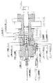
本発明を実施するために用いるせん断成形加工機は、図2から図5に示される設計図に従って組み立てられた装置から構成される。すなわち、高分子材料を投入する材料投入部としての試料投入部12を備えるシリンダー2と、このシリンダー2に取り付けられる混練部ヒーター13と、シリンダー2内に配設され、空洞部が設けられて、回転してせん断流動場を発生するための内部帰還型スクリュー1と、上記高分子材料を混練して得られた高分子ブレンド材を取り出す排出口としてのフィルム排出口10とを少なくとも備えている。好ましくは、最先端部20とスクリュー前段21との距離(ギャップ22)を2ミリ、ならびにスクリュー空洞部内径23を2.5φに設定するのが望ましい。なお、ギャップ22を2ミリ以上、ならびにスクリュー空洞部内径23を2.5φ以上に設定すると、混練の効果が小さくなってしまう結果となり、期待する結果を得ることができない。
The shear forming machine used for carrying out the present invention is composed of apparatuses assembled according to the design drawings shown in FIGS. That is, a
ポリ弗化ビニリデンとナイロン11の混合物を混合させるには、混合物を粒状物の状態で混合させるドライブレンドによる方法を用いることができる。ドライブレンドは試料を真空中100℃で12時間乾燥後に行った。また、ホモポリマーの分子量が高剪断成形後に、どの程度低下するかの検証を行うため、分子量分布の狭いポリスチレンを用いて、スクリュー回転速度ならびに混練時間依存性を検討した。ポリスチレンの予備乾燥は90℃で12時間行った。 In order to mix the mixture of polyvinylidene fluoride and nylon 11, a dry blending method in which the mixture is mixed in a granular state can be used. Dry blending was performed after the sample was dried in vacuum at 100 ° C. for 12 hours. In addition, in order to verify how much the molecular weight of the homopolymer decreases after high shear molding, the dependence on screw rotation speed and kneading time was examined using polystyrene with a narrow molecular weight distribution. The polystyrene was pre-dried at 90 ° C. for 12 hours.
前記のように、ドライブレンドしたのち、205〜215℃で所定の回転数で所定時間溶融混練し、T−ダイ9から押出し、冷却水槽24を通すことによる冷却過程を経てポリ弗化ビニリデンとナイロン11ブレンド押出し物が得られる。得られる押出し物の大きさは、シート状押出し物で厚さ0.5ミリ、幅30ミリである。ポリスチレンも同様に215〜225℃で所定の回転数で所定時間溶融混練し、T−ダイ9から押出し、冷却水槽24を通すことによる冷却過程を経てポリスチレンのシート状押出し物を得た。 As described above, after dry blending, it is melt-kneaded for a predetermined time at 205-215 ° C. at a predetermined rotation speed, extruded from the T-die 9, and passed through a cooling water tank 24 to be passed through a cooling water tank 24 to be polyvinylidene fluoride and nylon. An 11 blend extrudate is obtained. The size of the obtained extrudate is a sheet-like extrudate having a thickness of 0.5 mm and a width of 30 mm. Similarly, polystyrene was melt-kneaded for a predetermined time at 215 to 225 ° C. at a predetermined rotation number, extruded from the T-die 9, and subjected to a cooling process by passing through a cooling water tank 24 to obtain a sheet-like extrudate of polystyrene.
上記溶融混練機を用いる場合、最先端部20とスクリュー前段21とのギャップ22ならびに内部帰還型スクリュー内径23を調節することにより剪断もしくは混練の度合いを変えることができる。通常、ギャップ22は0ミリから5ミリの間の任意の値を0.5ミリ間隔で設定可能であり、スクリュー内径23も同様に1φから5φの間の任意の値を0.5φ間隔で設定可能であるが、ギャップ22ならびに内部帰還型スクリュー内径23を、それぞれ2ミリ、2.5φに設定することにより最適な結果を得ることができた。
When the melt kneader is used, the degree of shearing or kneading can be changed by adjusting the
本発明の場合には前記の特定の温度下に最先端部20とスクリュー前段21とのギャップ22ならびに内部帰還型スクリュー内径23を最適数値にして高剪断混合を行ったところに特徴がある。このように、特定の条件を組み合わせて初めて良好な結果が得られる。仮に温度設定あるいは上記ギャップ等の設定条件の一方でも、前記条件をはずれる場合には満足する結果を得ることができない。
The present invention is characterized in that high shear mixing is carried out with the
次に本発明を実施例によりさらに詳細に説明する。
本明細書で述べている微視的分散構造、重量平均分子量(Mw)は以下のように測定されたものである。
(微視的分散構造)
1)走査型電子顕微鏡(SEM)観察:構造観察に際し、四酸化オスミウム(OsO4)と、四酸化ルテニウム(RuO4)でブレンド試料を二重染色した後、ダイヤモンドナイフで切削し、イオンエッチング処理、白金コーティングした後、測定に供した。測定装置としては、日立製作所製電界放射走査型電子顕微鏡S800を用いて、加速電圧10KVにて倍率1000倍及び5000倍にて構造観察を行った。
2)透過型電子顕微鏡(TEM)観察:構造観察に際し、四酸化オスミウム(OsO4)と、四酸化ルテニウム(RuO4)でブレンド試料を二重染色した後、ウルトラミクロトーム(ライカ製ウルトラカットUCT)により、超薄切片(120nm)を作製し、コロジオン張り付けメッシュ上に展開した。測定装置としては、日本電子製JEM1230を用いて、加速電圧120kVにて行った。
(重量平均分子量:Mw)
測定は、JASCO GULLIVERシステムを用いて、Shodex K-804Lカラムにより紫外検出器(254nm)にて行った。移動相はクロロホルムを用いて、流速1mリットル/分、35℃で測定した。
Next, the present invention will be described in more detail with reference to examples.
The microscopic dispersion structure and weight average molecular weight (Mw) described in the present specification were measured as follows.
(Microscopic dispersion structure)
1) Scanning electron microscope (SEM) observation: When observing the structure, the blended sample was double-stained with osmium tetroxide (OsO 4 ) and ruthenium tetroxide (RuO 4 ), then cut with a diamond knife and ion-etched. After coating with platinum, it was subjected to measurement. The structure was observed using a field emission scanning electron microscope S800 manufactured by Hitachi, Ltd. at an acceleration voltage of 10 KV and magnifications of 1000 and 5000.
2) Observation with a transmission electron microscope (TEM): For structural observation, after blending a blend sample with osmium tetroxide (OsO 4 ) and ruthenium tetroxide (RuO 4 ), an ultramicrotome (Ultracut UCT manufactured by Leica) Thus, an ultrathin section (120 nm) was prepared and developed on a collodion-attached mesh. As a measuring apparatus, JEM1230 manufactured by JEOL Ltd. was used and the acceleration voltage was 120 kV.
(Weight average molecular weight: Mw)
The measurement was performed with a UV detector (254 nm) using a Shodex K-804L column using a JASCO GULLIVER system. The mobile phase was measured using chloroform at 35 ° C. with a flow rate of 1 ml / min.
<実施例1−1>
原料のポリフッ化ビニリデン(PVDF)はScientific Polymer Products社製、また、ナイロンとして、Aldrich社製のナイロン11(PA11)を用いた。両者を真空下100℃で12時間乾燥した後、室温でPVDF80重量%と、PA11を20重量%の割合でドライブレンドした。さらに、このドライブレンド物の約3gを本発明を実施するために用いるせん断成形加工機である微量型高剪断成形加工機に投入し、ギャップ22ならびに内部帰還型スクリュー内径23を、それぞれ2ミリ、2.5φに設定し、205〜215℃に加熱溶融して混練(スクリュー回転速度:2000rpm、混練時間:1分)し、T−ダイ9から押出し、冷却水槽24を通すことにより冷却固化したところ、表面状態の良好な押出し物を得ることができた。
<Example 1-1>
Polyvinylidene fluoride (PVDF) as a raw material was manufactured by Scientific Polymer Products, and nylon 11 (PA11) manufactured by Aldrich was used as nylon. Both were dried under vacuum at 100 ° C. for 12 hours, and then dry blended at room temperature with 80% by weight of PVDF and 20% by weight of PA11. Furthermore, about 3 g of this dry blend was put into a micro-type high shear molding machine which is a shear molding machine used for carrying out the present invention , and the
<実施例1−2>
本装置を用いた高剪断成形加工により、ホモポリマーの分子量がどの程度低下するかの検証を行うため、分子量分布の狭いポリスチレン(重量平均分子量Mw:106000、分子量分布Mw/Mn=1.06)を用いて、215〜225℃に加熱溶融してスクリュー回転速度ならびに混練時間依存性を検討した。スクリュー回転速度として、500rpmから3000rpm、混練時間として0.5分から8分まで変化させた。
<Example 1-2>
Polystyrene with a narrow molecular weight distribution (weight average molecular weight Mw: 106000, molecular weight distribution Mw / Mn = 1.06) in order to verify how much the molecular weight of the homopolymer is reduced by high shear molding using this apparatus. Was used and heated and melted at 215 to 225 ° C., and the screw rotation speed and kneading time dependence were examined. The screw rotation speed was changed from 500 rpm to 3000 rpm, and the kneading time was changed from 0.5 minutes to 8 minutes.
<実施例1−3>
実施例1−1において作製したPVDF/PA11=80/20ブレンド試料の走査型電子顕微鏡による測定結果を図6に示す。図に示されるように、PVDFリッチな系では、PVDFとPA11とは微視的な共連続構造(両方の高分子成分が微視的に相互に連続的に繋がった構造)を形成していることが分かった。図中、黒い部分がPA11ドメインであり、白っぽく見える部分はPVDFドメイン中にナノレベルのPA11ドメインが入りこんでいるものである。
<Example 1-3>
The measurement results by the scanning electron microscope of PVDF / PA11 = 80/20 blend samples prepared in Example 1 -1 shown in Fig. As shown in the figure, in a PVDF rich system, PVDF and PA11 form a microscopic co-continuous structure (a structure in which both polymer components are microscopically continuously connected to each other). I understood that. In the figure, the black portion is the PA11 domain, and the portion that appears whitish is that in which the nano-level PA11 domain has entered the PVDF domain.
<実施例1−4>
実施例1−1において作製したPVDF/PA11=80/20ブレンド試料の倍率をさらに上げ、PVDFドメイン中にナノレベルのPA11ドメインが入りこんでいる構造を透過電子顕微鏡で観察したのが図7である。図7右の写真において、白い部分がPVDFドメインであり、その中に分散している黒い部分(小さな丸)がPA11ドメインである。ここでは、100nmレベルのものと、さらに小さな10〜数10nmレベルのPA11ドメインが存在することが分かった。
<Example 1-4>
Further increasing the magnification of the prepared in Example 1 -1 PVDF / PA11 = 80/ 20 blend sample is in Figure 7 for the structure PA11 domain of nano level is just enters into the PVDF domain was observed by a transmission electron microscope . In the photograph on the right side of FIG. 7 , the white part is the PVDF domain, and the black part (small circles) dispersed therein is the PA11 domain. Here, it was found that there are PA11 domains at a level of 100 nm and a smaller level of 10 to several tens of nm.
<実施例1−5>
実施例1−2において作製したポリスチレン(PS)押出し物の重量平均分子量(Mw)とスクリュー回転速度との関係を図8に示す。この図において、混練時間は1分間とした。図に示されるように、スクリュー回転数が上昇するに従い、分子量も徐々に低下するが、その低下率はほぼ85%程度であることが分かった。
<Example 1-5>
The relationship between the weight average molecular weight of polystyrene (PS) extrudate prepared in Example 1 2 (Mw) to the screw rotational speed shown in FIG. In this figure, the kneading time was 1 minute. As shown in the figure, it was found that the molecular weight gradually decreased as the screw rotation speed increased, but the decrease rate was about 85%.
<実施例1−6>
実施例1−2において作製したポリスチレン(PS)押出し物の重量平均分子量(Mw)と混練時間との関係を図9に示す。図において、スクリュー回転速度として500rpmと1000rpmの2通りを選んだ。図からも分かるように、混練時間が増すにつれて、分子量も徐々に低下するが、その低下率はほぼ85%程度であることが分かった。
<Example 1-6>
The weight average molecular weight of polystyrene (PS) extrudate prepared in Example 1 2 (Mw) to the relation between kneading time shown in FIG. In the figure, two screw rotation speeds of 500 rpm and 1000 rpm were selected. As can be seen from the figure, the molecular weight gradually decreased as the kneading time increased, but the decrease rate was found to be about 85%.
本発明で用いるポリフッ化ビニリデン(PVDF)とポリアミド11(PA11)の混合物を混練させるには、混合物を粒状物の状態で混合させるドライブレンドによる方法を用いることができる。ドライブレンドは試料を真空中100℃で12時間乾燥後に行った。 In order to knead the mixture of polyvinylidene fluoride (PVDF) and polyamide 11 (PA11) used in the present invention, a method by dry blending in which the mixture is mixed in the form of granules can be used. Dry blending was performed after the sample was dried in vacuum at 100 ° C. for 12 hours.
PVDFとPA11とは、非相溶性であり、それらのブレンド物を得るには、通常、両者を融点近傍の200〜240℃で二軸の溶融混練機等を用いて混合するが、それらの押出し物の内部構造は一方の成分をマトリクスとした場合、他方の成分の分散相サイズが数ミクロン〜数十ミクロンメーターレベルにまで粗大化した、いわゆる相分離した構造となってしまう。 PVDF and PA11 are incompatible, and in order to obtain a blend thereof, they are usually mixed using a biaxial melt kneader or the like at 200 to 240 ° C. near the melting point. When one component is a matrix, the internal structure of the product becomes a so-called phase-separated structure in which the dispersed phase size of the other component is coarsened to a level of several microns to several tens of micrometers.
本発明者らの研究によれば、PVDFとPA11からなるブレンドを、通常の二軸スクリュー型混練機の代わりに内部帰還型スクリュー搭載の微量型高せん断成形加工機を用いて両者を融点近傍の200〜240℃で溶融混練することにより、十〜数十ナノメーターのPA11分散相がPVDFマトリクス相に均一かつ密に分散している、ナノ分散構造を有するブレンド押出し物が得られることを見出した。 According to the researches of the present inventors, a blend consisting of PVDF and PA11 was mixed with a micro-high shear molding machine equipped with an internal feedback screw instead of a normal biaxial screw kneader, and both of them were in the vicinity of the melting point. It has been found that a blended extrudate having a nano-dispersed structure in which a PA11 dispersed phase of 10 to several tens of nanometers is uniformly and densely dispersed in a PVDF matrix phase can be obtained by melt-kneading at 200 to 240 ° C. .
上記内部帰還型スクリュー搭載の微量型高せん断成形加工機を用いる場合、成形加工条件としては上記の特定温度の設定だけでなく、当該成形加工機におけるスクリュー回転数と混練時間の設定が重要である。本発明では、スクリュー回転数として500〜3000rpm、混練時間として0.5分〜60分の間で設定可能であるが、回転数ならびに混練時間として、それぞれ1000〜2000rpm、1〜4分に設定することにより最適な結果を得ることができた。 When using the above-mentioned trace amount type high shear molding machine equipped with an internal feedback screw, not only the setting of the above specific temperature but also the setting of the screw speed and kneading time in the molding machine are important as the molding process conditions. . In the present invention, the screw rotation speed can be set to 500 to 3000 rpm, and the kneading time can be set to 0.5 to 60 minutes, but the rotation speed and kneading time are set to 1000 to 2000 rpm and 1 to 4 minutes, respectively. As a result, optimum results were obtained.
本発明の場合には前記の特定の温度下にスクリュー回転数と混練時間を最適数値にして高せん断成形を行ったところに特徴がある。このように、特定の条件を組み合わせて初めて良好な結果が得られる。仮に温度設定あるいは上記スクリュー回転数等の設定条件の一方でも、前記条件をはずれる場合には満足する結果を得ることができない。 The present invention is characterized in that high shear molding is carried out with the screw rotation speed and kneading time set to optimum values under the specific temperature. Thus, good results can be obtained only by combining specific conditions. Even if one of the setting conditions such as the temperature setting or the screw rotation speed is not satisfied, a satisfactory result cannot be obtained.
上記内部帰還型スクリュー搭載の微量型高せん断成形加工機を用いる場合、ブレンド物が充填されているシリンダー最先端部とスクリュー先端部とのギャップ、あるいは内部帰還型スクリューの内径を調節することによりせん断流動場の強さもしくは混練の度合いを変えることができる。通常、ギャップは1ミリから5ミリの間で任意の値を0.5ミリ間隔で設定可能であり、スクリュー内径も同様に1φから5φの間で任意の値を0.5φ間隔で設定可能であるが、ギャップならびに内部帰還型スクリュー内径を、それぞれ2ミリ、2.5φに設定することにより最適な結果を得ることができた。 When using the above-mentioned trace type high shear molding machine equipped with an internal feedback type screw, shearing is performed by adjusting the gap between the tip of the cylinder filled with the blend and the tip of the screw, or the inner diameter of the internal feedback type screw. The strength of the flow field or the degree of kneading can be changed. In general, the gap can be set to any value between 0.5mm and 1mm between 1mm and 5mm, and the screw inner diameter can be set to 0.5mm interval between 1φ and 5φ as well. However, the optimum results could be obtained by setting the gap and the internal feedback screw inner diameter to 2 mm and 2.5φ, respectively.
本発明の場合には前記の特定の温度下に最先端部とスクリュー先端部とのギャップならびに内部帰還型スクリュー内径を最適数値にして高せん断成形を行ったところに特徴がある。このように、特定の条件を組み合わせて初めて良好な結果が得られる。仮に温度設定あるいは上記ギャップ等の設定条件の一方でも、前記条件をはずれる場合には満足する結果を得ることができない。 The present invention is characterized in that high shear molding is carried out with the gap between the most advanced portion and the screw tip and the internal diameter of the internal feedback screw at optimum values under the specific temperature. Thus, good results can be obtained only by combining specific conditions. Even if one of the setting conditions such as the temperature setting or the gap is not satisfied, a satisfactory result cannot be obtained.
次に、本発明による混練についてさらに詳細に説明する。
ここで、本明細書で述べている微視的分散構造、応力-ひずみ曲線は以下のように測定されたものである。
(微視的分散構造)
透過型電子顕微鏡(TEM)観察:構造観察に際し、四酸化オスミウム(OsO4)と、四酸化ルテニウム(RuO4)でブレンド試料を二重染色した後、ウルトラミクロトーム(ライカ製ウルトラカットUCT)により、超薄切片(120nm)を作製し、コロジオン張り付けメッシュ上に展開した。測定装置としては、日本電子製JEM1230を用いて、加速電圧120kVにて行った。
(応力−ひずみ曲線)
応力−ひずみ曲線の測定は、オリエンテック(株)社製Tensilon UMT-300を用いてダンベル型試料により行った。本測定は、速度5mm/min.、温度20℃、相対湿度50%で行った。
Next, the kneading according to the present invention will be described in more detail.
Here, the microscopic dispersion structure and the stress-strain curve described in the present specification were measured as follows.
(Microscopic dispersion structure)
Transmission electron microscope (TEM) observation: For structural observation, after double-staining the blend sample with osmium tetroxide (OsO 4 ) and ruthenium tetroxide (RuO 4 ), ultramicrotome (Ultracut UCT manufactured by Leica) Ultrathin sections (120 nm) were prepared and developed on collodion-laminated mesh. As a measuring apparatus, JEM1230 manufactured by JEOL Ltd. was used and the acceleration voltage was 120 kV.
(Stress-strain curve)
The stress-strain curve was measured with a dumbbell sample using Tensilon UMT-300 manufactured by Orientec Co., Ltd. This measurement is performed at a speed of 5 mm / min. At a temperature of 20 ° C. and a relative humidity of 50%.
<実施例2−1>
原料のポリフッ化ビニリデン(PVDF)は呉羽化学工業(株)社製KF850、また、ポリアミド11(PA11)として、Atfina社製のRilsan BMN-Oを用いた。両者を真空下100℃で12時間乾燥した後、室温でPVDF90〜20重量%とPA11の10〜80重量%の割合でドライブレンドした。さらに、このドライブレンド物の2〜5gを、本発明を実施するために用いるせん断成形加工機である微量型高せん断成形加工機に投入し、ギャップならびに内部帰還型スクリュー内径を、それぞれ2ミリ、2.5φに設定し、200〜240℃に加熱溶融して混練(スクリュー回転数:1000rpm、混練時間:1分)し、T−ダイから押出し、冷却水槽を通すことにより冷却固化したところ、表面状態の良好な押出し物を得ることができた。
<Example 2-1>
The raw material polyvinylidene fluoride (PVDF) used was KF850 manufactured by Kureha Chemical Industry Co., Ltd., and Rilsan BMN-O manufactured by Atfina was used as polyamide 11 (PA11). Both were dried at 100 ° C. for 12 hours under vacuum, and then dry blended at a ratio of 90 to 20% by weight of PVDF and 10 to 80% by weight of PA11 at room temperature. Furthermore, the 2~5g of the dry blend, the present invention was placed in micro-volume high-shear processing machine is a shear processing machine used to implement, the gap and internal feedback screw inner diameter, respectively 2 mm Set to 2.5φ, heated and melted at 200 to 240 ° C., kneaded (screw rotation speed: 1000 rpm, kneading time: 1 minute), extruded from a T-die, and cooled and solidified by passing through a cooling water bath. An extrudate having a good state could be obtained.
<実施例2−2>
実施例2−1において作製したPVDF/PA11=90/10ブレンド試料において、PVDFマトリクス中にナノレベルのPA11ドメインが入りこんでいる構造を透過電子顕微鏡(TEM)で観察したのが図10である。図10の写真において、白い部分がPVDFマトリクス相であり、その中に分散している黒く染色された部分(小さな丸)がPA11ドメインである。ここでは、十〜数十ナノメーターレベルのPA11ドメインが均一かつ密にPVDFマトリクス相に存在することが分かった。このようなナノ分散構造はPVDF/PA11=90/10〜20/80ブレンドという広範なブレンド組成において観察することができた。
<Example 2-2>
In the PVDF / PA11 = 90/10 blend sample prepared in Example 2-1, the structure in which the nano-level PA11 domain has entered the PVDF matrix is observed with a transmission electron microscope (TEM) in FIG. In the photograph of FIG. 10, the white part is the PVDF matrix phase, and the black-stained part (small circles) dispersed therein is the PA11 domain. Here, it has been found that PA11 domains of ten to several tens of nanometer level exist uniformly and densely in the PVDF matrix phase. Such a nano-dispersed structure could be observed in a wide range of blend compositions of PVDF / PA11 = 90 / 10-20 / 80 blend.
<実施例2−3>
実施例2−1において作製したPVDF/PA11=80/20ブレンド試料において応力−ひずみ曲線を測定したのが図11である。図11において曲線bは通常の成形加工機により作製したブレンド押出し物による結果である。本発明により作製した押出し物による結果(曲線c)はbの5〜6倍の伸びを示すだけでなく、ほぼ純粋なPA11に匹敵する特性を示すことが分かった。
<Example 2-3>
FIG. 11 shows the stress-strain curve measured for the PVDF / PA11 = 80/20 blend sample prepared in Example 2-1. In FIG. 11, curve b is the result of the blend extrudate produced by a normal molding machine. It was found that the results with extrudates made according to the invention (curve c) not only show 5-6 times the elongation of b, but also show properties comparable to almost pure PA11.
上記では、サンプル量は実施例で2g〜5gとしたが、スケールアップにより、サンプル量を増大させる事が出来る。また、高温用シールを取り付ける事により500℃までの高温での混練を行なう事が可能である。そして図中には記していないが混練中の剪断加熱による温度上昇をシリンダーを冷却する事に設定温度を保つ構造を付加しても良い。 In the above, the sample amount is 2 g to 5 g in the embodiment, but the sample amount can be increased by scaling up. Further, kneading at a high temperature up to 500 ° C. can be performed by attaching a high-temperature seal. Although not shown in the figure, a structure that maintains the set temperature may be added by cooling the cylinder due to the temperature rise caused by shear heating during kneading.
1 高分子材料を混練する為のスクリュー
2 スクリューとの組み合わせより混練部を作る為のシリンダー
3 このシリンダを動かす事によりギャップの調整が設定できるギャップ調整シリンダ
4 シリンダー内部より混練された高分子材料が外に漏れない為の漏れ防止用シール
5 主に混練部よりTダイへ流し込む為の押出し先端部
6 混練時、混練部より流れるのを防ぐ為の物と同時にT混練された高分子材料をTダイに流し込む際に開く為の開閉バルブ
7 混練部の温度を測る為の熱電対
8 高分子材料を混練する為の混練部
9 混練された高分子材料をフィルム状にする為のフィルム作成用Tダイ
10 混練された高分子材料をフィルムにした状態で排出されるフィルム排出口
11 Tダイ部の温度を測る為の熱電対
12 高分子材料を入れる試料投入部
13 混練部を加熱する為の混練部ヒーター
14 押出し先端部を加熱する為の押出し先端部ヒーター
15 試料投入部を加熱する為の試料投入部ヒーター
16 Tダイ前部を加熱する為のTダイ前部ヒーター
17 Tダイ後部を加熱する為のTダイ後部ヒーター
18 回転時スクリューを安定させる為のベアリング
19 モーターよりスクリューに伝動させるた為のシャフト
20 ギャップ調整時に読取の必要な場所である最先端部
21 ギャップ調整時に読取の必要な場所であるスクリュー前段
22 ギャップの調整範囲
23 スクリュー内径の調整範囲
24 Tダイより排出されたフィルム状のサンプルを急冷させる為に水を入れる冷却水槽
25 混練時にスクリューを回転させる為のモータ
26 シリンダーを固定させる為のシリンダーロック
27 シリンダーロックとシリンダー後部に熱を逃がす為の冷却板
28 モーターの運転停止、加熱の制御など作業に必要なスイッチが配属されいている制御BOX
1 Screw for kneading polymer material 2 Cylinder for making kneading part by combining with screw 3 Gap adjustment cylinder that can set gap adjustment by moving this cylinder 4 Polymer material kneaded from inside cylinder Seal for preventing leakage to prevent leakage to the outside 5 Extrusion tip for mainly flowing from the kneading section to the T die 6 T Open / close valve to open when pouring into the die 7 Thermocouple to measure the temperature of the kneading part 8 Kneading part to knead the polymer material 9 Film making T to make the kneaded polymer material into a film Die 10 Film outlet 11 for discharging the kneaded polymer material in a film state Thermocouple 12 for measuring temperature of T die part Feeding section 13 Kneading section heater 14 for heating the kneading section Extrusion tip section heater 15 for heating the extrusion tip section Sample loading section heater 16 for heating the sample loading section T T die front section heating T-die front heater 17 T-die rear heater 18 for heating the rear part of the T die 19 Bearing 19 for stabilizing the screw during rotation 19 Shaft 20 for transmitting power from the motor to the screw This is a place that needs to be read when adjusting the gap The most advanced part 21 The front stage of the screw, which is a place that needs to be read at the time of gap adjustment 22 The gap adjustment range 23 The screw inner diameter adjustment range 24 The cooling water tank 25 into which water is put to rapidly cool the film-like sample discharged from the T-die A motor to rotate the screw at times 26 Cylinder lock to fix the cylinder 7 Cylinder lock and cooling plate 28 outage motor for releasing the heat to the cylinder rear, control switches required to work such as control of the heating has not been assigned BOX
Claims (2)
非相溶性高分子ブレンド系の高分子材料を、相容化剤を添加することなく、上記シリンダー内に配設され、空洞部内径が1mmから5mmの間である内部帰還型スクリューの後段へ投入する工程と、
上記内部帰還型スクリューを500rpm〜3000rpmで回転してせん断流動場を高めて発生させ、投入した上記高分子材料を、上記内部帰還型スクリューによって前段にフィードしながら混練すると共に上記シリンダーの最先端部に到達させて、この最先端部と上記内部帰還型スクリューの先端部とのギャップに充填し、このギャップに充填した上記高分子材料を上記内部帰還型スクリューの空洞部内を通して、再び上記後段に戻すことを上記シリンダー内で繰り返すことで、上記高分子材料を循環させて繰り返し混練する工程と、
上記繰り返し混練する工程により得られた高分子ブレンド材を上記シリンダーから排出する工程と、
を備え、
上記高分子ブレンド材は、一方の高分子成分がマトリックスであり、他方の高分子成分が数十ナノメートルサイズの分散相である、
ことを特徴とする高分子ブレンド材の製造方法。 A method for producing a polymer blend material, in which a polymer material is kneaded in a molten state in a cylinder and a polymer blend material is produced by a shear molding process,
An incompatible polymer blend-based polymer material is placed in the latter stage of the internal feedback screw that is disposed in the cylinder and has an inner diameter of 1 to 5 mm without adding a compatibilizer. And a process of
The internal feedback screw is rotated at 500 rpm to 3000 rpm to increase the shear flow field, and the charged polymer material is kneaded while being fed to the previous stage by the internal feedback screw and the most advanced part of the cylinder And the gap between the leading edge and the tip of the internal feedback screw is filled, and the polymer material filled in the gap is returned to the subsequent stage through the cavity of the internal feedback screw. By repeating this in the cylinder, the step of circulating and kneading the polymer material repeatedly,
Discharging the polymer blend material obtained by the kneading step from the cylinder;
With
In the polymer blend material, one polymer component is a matrix, and the other polymer component is a dispersed phase having a size of several tens of nanometers.
A method for producing a polymer blend material.
ことを特徴とする請求項1に記載の高分子ブレンド材の製造方法。The manufacturing method of the polymer blend material of Claim 1 characterized by the above-mentioned.
Priority Applications (1)
| Application Number | Priority Date | Filing Date | Title |
|---|---|---|---|
| JP2005053251A JP4745684B2 (en) | 2004-03-31 | 2005-02-28 | Method for producing polymer blend material |
Applications Claiming Priority (3)
| Application Number | Priority Date | Filing Date | Title |
|---|---|---|---|
| JP2004108130 | 2004-03-31 | ||
| JP2004108130 | 2004-03-31 | ||
| JP2005053251A JP4745684B2 (en) | 2004-03-31 | 2005-02-28 | Method for producing polymer blend material |
Related Child Applications (1)
| Application Number | Title | Priority Date | Filing Date |
|---|---|---|---|
| JP2010260116A Division JP5238926B2 (en) | 2004-03-31 | 2010-11-22 | Shear forming machine |
Publications (3)
| Publication Number | Publication Date |
|---|---|
| JP2005313608A JP2005313608A (en) | 2005-11-10 |
| JP2005313608A5 JP2005313608A5 (en) | 2006-10-05 |
| JP4745684B2 true JP4745684B2 (en) | 2011-08-10 |
Family
ID=35441513
Family Applications (1)
| Application Number | Title | Priority Date | Filing Date |
|---|---|---|---|
| JP2005053251A Active JP4745684B2 (en) | 2004-03-31 | 2005-02-28 | Method for producing polymer blend material |
Country Status (1)
| Country | Link |
|---|---|
| JP (1) | JP4745684B2 (en) |
Families Citing this family (41)
| Publication number | Priority date | Publication date | Assignee | Title |
|---|---|---|---|---|
| JP4868396B2 (en) * | 2006-05-09 | 2012-02-01 | 独立行政法人産業技術総合研究所 | Nylon-6 / polyvinylidene fluoride blend film and method for producing the same |
| US8349953B2 (en) | 2006-08-17 | 2013-01-08 | National Institute Of Advanced Industrial Science And Technology | Resin melting and shearing method, resin molding processing method and resin products |
| JP5207351B2 (en) | 2007-03-23 | 2013-06-12 | 独立行政法人産業技術総合研究所 | Melt-kneaded product, resin molded product and method for producing the same |
| JP2009029114A (en) * | 2007-06-22 | 2009-02-12 | National Institute Of Advanced Industrial & Technology | Production method of filler-dispersed melt-kneaded product, molded resin product obtained by production method of melt-kneaded product, and production method or use thereof |
| US8048948B2 (en) | 2007-06-22 | 2011-11-01 | National Institute Of Advanced Industrial Science And Technology | Filler-dispersed melt-kneaded products, molded resin products thereof, and production method thereof |
| JP5152711B2 (en) | 2007-07-06 | 2013-02-27 | 独立行政法人産業技術総合研究所 | Structure composed of filler and incompatible resin or elastomer, production method thereof and use thereof |
| JP2009196196A (en) * | 2008-02-21 | 2009-09-03 | National Institute Of Advanced Industrial & Technology | Melt kneading method, molding processing method, and resin molded product of polycarbonate and polymethyl methacrylate |
| JP5292854B2 (en) * | 2008-02-29 | 2013-09-18 | 東レ株式会社 | Thermoplastic resin composition and method for producing the same |
| JP5333723B2 (en) * | 2008-07-23 | 2013-11-06 | 住友ゴム工業株式会社 | Rubber composition |
| JP5177748B2 (en) * | 2008-09-02 | 2013-04-10 | 独立行政法人産業技術総合研究所 | Aliphatic polyester composition and method for producing the same |
| KR101678239B1 (en) | 2008-11-26 | 2016-11-21 | 고쿠리츠켄큐카이하츠호진 상교기쥬츠 소고켄큐쇼 | Method of Melt Kneading, Extrudate, and Transparent Resin Material |
| JP2010155953A (en) * | 2009-01-05 | 2010-07-15 | National Institute Of Advanced Industrial Science & Technology | Structure composed of filler and non-compatible resin or elastomer, method for producing the same, and use of the same |
| US9199393B2 (en) | 2009-02-05 | 2015-12-01 | Niigata Machine Techno Co., Ltd. | High-shear melt-kneader and method of high shearing |
| JP5284814B2 (en) * | 2009-02-06 | 2013-09-11 | オリンパス株式会社 | Circulating kneader |
| JP5371526B2 (en) * | 2009-04-15 | 2013-12-18 | オリンパス株式会社 | Kneading machine and extrusion molding device |
| JP5420318B2 (en) * | 2009-06-12 | 2014-02-19 | オリンパス株式会社 | Kneading method and kneader |
| JP2011020341A (en) * | 2009-07-15 | 2011-02-03 | Olympus Corp | Kneader, molding apparatus, and method for producing fluid of kneaded substance |
| JP5379584B2 (en) * | 2009-07-15 | 2013-12-25 | オリンパス株式会社 | Kneading machine and molding device |
| JP5404236B2 (en) * | 2009-08-04 | 2014-01-29 | オリンパス株式会社 | Kneading device and kneading molding device |
| JP2011225832A (en) * | 2010-03-30 | 2011-11-10 | Sumitomo Chemical Co Ltd | Method of manufacturing thermoplastic resin composition |
| JP2011213050A (en) * | 2010-04-01 | 2011-10-27 | Olympus Corp | Kneading device and method for manufacturing resin using the same |
| JP5716307B2 (en) * | 2010-07-22 | 2015-05-13 | 株式会社三菱ケミカルホールディングス | Composite resin composition having vibration damping properties and method for producing the same |
| JP2012201790A (en) | 2011-03-25 | 2012-10-22 | Sumitomo Chemical Co Ltd | Method for producing modified propylene polymer |
| JP5838575B2 (en) | 2011-03-25 | 2016-01-06 | 住友化学株式会社 | Process for producing modified propylene polymer |
| JP5659900B2 (en) | 2011-03-25 | 2015-01-28 | 住友化学株式会社 | Modified propylene polymer |
| JP5822119B2 (en) * | 2011-09-29 | 2015-11-24 | 株式会社ニイガタマシンテクノ | High shear processing equipment |
| WO2013108817A1 (en) | 2012-01-17 | 2013-07-25 | 独立行政法人産業技術総合研究所 | Plant-derived plastic blend and production method therefor |
| JP5911011B2 (en) * | 2012-03-13 | 2016-04-27 | 株式会社ニイガタマシンテクノ | High shear processing apparatus and separation method thereof |
| US9303112B2 (en) | 2012-09-24 | 2016-04-05 | Sumitomo Chemical Company, Limited | Propylene resin material and method for the production thereof |
| JP6446310B2 (en) | 2014-04-10 | 2018-12-26 | 東芝機械株式会社 | Screw for extruder, extruder and extrusion method |
| JP6527742B2 (en) * | 2014-04-24 | 2019-06-05 | 東芝機械株式会社 | Screw for extruder, extruder and extrusion method |
| JP6550253B2 (en) | 2014-04-24 | 2019-07-24 | 東芝機械株式会社 | Screw for extruder, extruder and extrusion method |
| JP6464025B2 (en) * | 2015-04-28 | 2019-02-06 | 東芝機械株式会社 | Screw for extruder, extruder and extrusion method |
| JP6746278B2 (en) * | 2015-04-28 | 2020-08-26 | 芝浦機械株式会社 | Extruder screw, extruder and extrusion method |
| CN110799593B (en) | 2017-06-28 | 2022-10-21 | 大金工业株式会社 | Resin composition and molded article |
| JP2019199003A (en) * | 2018-05-15 | 2019-11-21 | 東芝機械株式会社 | Method for producing conductive composite material |
| JP7181465B2 (en) | 2019-03-27 | 2022-12-01 | ダイキン工業株式会社 | Resin composition and molded product |
| EP4194487A1 (en) | 2020-08-07 | 2023-06-14 | Daikin Industries, Ltd. | Film, wrapping electric wire coating material, film for flexible printed circuit board, and laminate |
| CN116323817A (en) | 2020-09-30 | 2023-06-23 | 大金工业株式会社 | Powder composition, coating film and three-dimensional molded article |
| CN116323764A (en) | 2020-09-30 | 2023-06-23 | 大金工业株式会社 | Composition for three-dimensional modeling and three-dimensional modeling object |
| WO2022071142A1 (en) | 2020-09-30 | 2022-04-07 | ダイキン工業株式会社 | Insulated electrical wire and resin composition |
Family Cites Families (11)
| Publication number | Priority date | Publication date | Assignee | Title |
|---|---|---|---|---|
| GB1501412A (en) * | 1974-04-11 | 1978-02-15 | Scient Process & Res Inc | Apparatus for preparing a plasticated material |
| JPS5329741Y2 (en) * | 1976-05-10 | 1978-07-25 | ||
| JPS5573330U (en) * | 1978-11-15 | 1980-05-20 | ||
| JPH082532B2 (en) * | 1988-10-11 | 1996-01-17 | 東芝シリコーン株式会社 | Method for continuously producing heat-vulcanizable silicone rubber compound |
| JP4030150B2 (en) * | 1997-03-31 | 2008-01-09 | 東京インキ株式会社 | Production method of polymer blend |
| JP3597070B2 (en) * | 1999-01-20 | 2004-12-02 | 東芝機械株式会社 | Apparatus and method for producing impact-resistant thermoplastic resin |
| JP4023058B2 (en) * | 2000-01-05 | 2007-12-19 | 三菱化学株式会社 | Process for producing olefinic thermoplastic elastomer |
| JP5258130B2 (en) * | 2001-07-11 | 2013-08-07 | 旭化成ケミカルズ株式会社 | Colored polycarbonate flame retardant resin composition and method for producing the same |
| JP2003119292A (en) * | 2001-08-08 | 2003-04-23 | Calp Corp | Production method for molding material, and molded article |
| JP3773439B2 (en) * | 2001-10-24 | 2006-05-10 | 株式会社ユポ・コーポレーション | Resin film |
| JPWO2003077827A1 (en) * | 2002-03-19 | 2005-07-14 | 日本新薬株式会社 | Method for producing pharmaceutical solid dispersion |
-
2005
- 2005-02-28 JP JP2005053251A patent/JP4745684B2/en active Active
Also Published As
| Publication number | Publication date |
|---|---|
| JP2005313608A (en) | 2005-11-10 |
Similar Documents
| Publication | Publication Date | Title |
|---|---|---|
| JP4745684B2 (en) | Method for producing polymer blend material | |
| US8975336B2 (en) | Method of melt kneading, extrudate, and transparent resin material | |
| Li et al. | Effect of chain extension on the properties of PLA/TPS blends | |
| Nofar et al. | Ductility improvements of PLA-based binary and ternary blends with controlled morphology using PBAT, PBSA, and nanoclay | |
| JP5177748B2 (en) | Aliphatic polyester composition and method for producing the same | |
| Favis et al. | Factors influencing structure formation and phase size in an immiscible polymer blend of polycarbonate and polypropylene prepared by twin-screw extrusion | |
| Nuñez et al. | Nanocomposites of PLA/PP blends based on sepiolite | |
| Ren et al. | Effect of dual reactive compatibilizers on the formation of co-continuous morphology of low density polyethylene/polyamide 6 blends with low polyamide 6 content | |
| Basseri et al. | Relationship among microstructure, linear viscoelastic behavior and mechanical properties of SBS triblock copolymer-compatibilized PP/SAN blend | |
| Breuer et al. | The design and performance of a new miniature mixer for specialty polymer blends and nanocomposites | |
| Krache et al. | Binary and ternary blends of polyethylene, polypropylene, and polyamide 6, 6: The effect of compatibilization on the morphology and rheology | |
| JP2009196196A (en) | Melt kneading method, molding processing method, and resin molded product of polycarbonate and polymethyl methacrylate | |
| EP3268425B1 (en) | A polymer nanocomposite, process and applications thereof | |
| JP5238926B2 (en) | Shear forming machine | |
| JP6340196B2 (en) | Plant-derived plastic blend and method for producing the same | |
| US20120327737A1 (en) | Resin melting and shearing method, resin molding processing method and resin products | |
| Jazani et al. | Study on the effect of processing conditions on the impact strength of PP/SEBS/PC ternary blends using Taguchi experimental analysis | |
| Kirschnick et al. | Melt processed blends of poly (styrene-co-acrylonitrile) and poly (phenylene ether) compatibilized with polystyrene-b-polybutadiene-b-poly (methyl methacrylate) triblock terpolymers | |
| Zhou et al. | Morphologies, interfacial interaction and mechanical performance of super-tough nanostructured PK/PA6 blends | |
| Torres et al. | Effects of the blending sequence and interfacial agent on the morphology and mechanical properties of injection molded PC/PP Blends | |
| Guo et al. | A study on weld line morphology and mechanical strength of injection molded polystyrene/poly (methyl methacrylate) blends | |
| JP6532628B2 (en) | Multi-spindle kneader, method of producing nanocomposite using the multi-spindle kneader, and disc type segment used therefor | |
| Jurkowski et al. | Influence of chemical and mechanical compatibilization on structure and properties of polyethylene/polyamide blends | |
| Madbouly et al. | Morphology and properties of novel blends prepared from simultaneous in situ polymerization and compatibilization of macrocyclic carbonates and maleated poly (propylene) | |
| Shimizu et al. | High-shear effects on the nano-dispersed structure of the PVDF/PA11 blends |
Legal Events
| Date | Code | Title | Description |
|---|---|---|---|
| A521 | Request for written amendment filed |
Free format text: JAPANESE INTERMEDIATE CODE: A523 Effective date: 20060809 |
|
| A621 | Written request for application examination |
Free format text: JAPANESE INTERMEDIATE CODE: A621 Effective date: 20071025 |
|
| A521 | Request for written amendment filed |
Free format text: JAPANESE INTERMEDIATE CODE: A523 Effective date: 20071026 |
|
| A977 | Report on retrieval |
Free format text: JAPANESE INTERMEDIATE CODE: A971007 Effective date: 20100609 |
|
| A131 | Notification of reasons for refusal |
Free format text: JAPANESE INTERMEDIATE CODE: A131 Effective date: 20100615 |
|
| A521 | Request for written amendment filed |
Free format text: JAPANESE INTERMEDIATE CODE: A523 Effective date: 20100816 |
|
| A131 | Notification of reasons for refusal |
Free format text: JAPANESE INTERMEDIATE CODE: A131 Effective date: 20100921 |
|
| A521 | Request for written amendment filed |
Free format text: JAPANESE INTERMEDIATE CODE: A523 Effective date: 20101122 |
|
| A131 | Notification of reasons for refusal |
Free format text: JAPANESE INTERMEDIATE CODE: A131 Effective date: 20110111 |
|
| A521 | Request for written amendment filed |
Free format text: JAPANESE INTERMEDIATE CODE: A523 Effective date: 20110311 |
|
| A521 | Request for written amendment filed |
Free format text: JAPANESE INTERMEDIATE CODE: A821 Effective date: 20110311 |
|
| TRDD | Decision of grant or rejection written | ||
| A01 | Written decision to grant a patent or to grant a registration (utility model) |
Free format text: JAPANESE INTERMEDIATE CODE: A01 Effective date: 20110412 |
|
| A61 | First payment of annual fees (during grant procedure) |
Free format text: JAPANESE INTERMEDIATE CODE: A61 Effective date: 20110512 |
|
| FPAY | Renewal fee payment (event date is renewal date of database) |
Free format text: PAYMENT UNTIL: 20140520 Year of fee payment: 3 |
|
| R150 | Certificate of patent or registration of utility model |
Ref document number: 4745684 Country of ref document: JP Free format text: JAPANESE INTERMEDIATE CODE: R150 Free format text: JAPANESE INTERMEDIATE CODE: R150 |
|
| R250 | Receipt of annual fees |
Free format text: JAPANESE INTERMEDIATE CODE: R250 |
|
| S111 | Request for change of ownership or part of ownership |
Free format text: JAPANESE INTERMEDIATE CODE: R313117 |
|
| R350 | Written notification of registration of transfer |
Free format text: JAPANESE INTERMEDIATE CODE: R350 |
|
| S533 | Written request for registration of change of name |
Free format text: JAPANESE INTERMEDIATE CODE: R313533 |
|
| R350 | Written notification of registration of transfer |
Free format text: JAPANESE INTERMEDIATE CODE: R350 |
|
| R250 | Receipt of annual fees |
Free format text: JAPANESE INTERMEDIATE CODE: R250 |
|
| R250 | Receipt of annual fees |
Free format text: JAPANESE INTERMEDIATE CODE: R250 |
|
| R250 | Receipt of annual fees |
Free format text: JAPANESE INTERMEDIATE CODE: R250 |
|
| S531 | Written request for registration of change of domicile |
Free format text: JAPANESE INTERMEDIATE CODE: R313531 |
|
| R250 | Receipt of annual fees |
Free format text: JAPANESE INTERMEDIATE CODE: R250 |
|
| S111 | Request for change of ownership or part of ownership |
Free format text: JAPANESE INTERMEDIATE CODE: R313117 |
|
| R350 | Written notification of registration of transfer |
Free format text: JAPANESE INTERMEDIATE CODE: R350 |
|
| R350 | Written notification of registration of transfer |
Free format text: JAPANESE INTERMEDIATE CODE: R350 |
|
| R250 | Receipt of annual fees |
Free format text: JAPANESE INTERMEDIATE CODE: R250 |