JP4738690B2 - Filter apparatus and method - Google Patents
Filter apparatus and method Download PDFInfo
- Publication number
- JP4738690B2 JP4738690B2 JP2001536270A JP2001536270A JP4738690B2 JP 4738690 B2 JP4738690 B2 JP 4738690B2 JP 2001536270 A JP2001536270 A JP 2001536270A JP 2001536270 A JP2001536270 A JP 2001536270A JP 4738690 B2 JP4738690 B2 JP 4738690B2
- Authority
- JP
- Japan
- Prior art keywords
- filter element
- flange
- sleeve member
- filter
- end portion
- Prior art date
- Legal status (The legal status is an assumption and is not a legal conclusion. Google has not performed a legal analysis and makes no representation as to the accuracy of the status listed.)
- Expired - Lifetime
Links
Images


Classifications
-
- B—PERFORMING OPERATIONS; TRANSPORTING
- B01—PHYSICAL OR CHEMICAL PROCESSES OR APPARATUS IN GENERAL
- B01D—SEPARATION
- B01D46/00—Filters or filtering processes specially modified for separating dispersed particles from gases or vapours
-
- B—PERFORMING OPERATIONS; TRANSPORTING
- B01—PHYSICAL OR CHEMICAL PROCESSES OR APPARATUS IN GENERAL
- B01D—SEPARATION
- B01D46/00—Filters or filtering processes specially modified for separating dispersed particles from gases or vapours
- B01D46/52—Particle separators, e.g. dust precipitators, using filters embodying folded corrugated or wound sheet material
- B01D46/521—Particle separators, e.g. dust precipitators, using filters embodying folded corrugated or wound sheet material using folded, pleated material
-
- B—PERFORMING OPERATIONS; TRANSPORTING
- B01—PHYSICAL OR CHEMICAL PROCESSES OR APPARATUS IN GENERAL
- B01D—SEPARATION
- B01D46/00—Filters or filtering processes specially modified for separating dispersed particles from gases or vapours
- B01D46/0001—Making filtering elements
-
- B—PERFORMING OPERATIONS; TRANSPORTING
- B01—PHYSICAL OR CHEMICAL PROCESSES OR APPARATUS IN GENERAL
- B01D—SEPARATION
- B01D46/00—Filters or filtering processes specially modified for separating dispersed particles from gases or vapours
- B01D46/0002—Casings; Housings; Frame constructions
- B01D46/0005—Mounting of filtering elements within casings, housings or frames
-
- B—PERFORMING OPERATIONS; TRANSPORTING
- B01—PHYSICAL OR CHEMICAL PROCESSES OR APPARATUS IN GENERAL
- B01D—SEPARATION
- B01D46/00—Filters or filtering processes specially modified for separating dispersed particles from gases or vapours
- B01D46/10—Particle separators, e.g. dust precipitators, using filter plates, sheets or pads having plane surfaces
- B01D46/12—Particle separators, e.g. dust precipitators, using filter plates, sheets or pads having plane surfaces in multiple arrangements
-
- B—PERFORMING OPERATIONS; TRANSPORTING
- B01—PHYSICAL OR CHEMICAL PROCESSES OR APPARATUS IN GENERAL
- B01D—SEPARATION
- B01D46/00—Filters or filtering processes specially modified for separating dispersed particles from gases or vapours
- B01D46/24—Particle separators, e.g. dust precipitators, using rigid hollow filter bodies
- B01D46/2403—Particle separators, e.g. dust precipitators, using rigid hollow filter bodies characterised by the physical shape or structure of the filtering element
- B01D46/2411—Filter cartridges
-
- B—PERFORMING OPERATIONS; TRANSPORTING
- B01—PHYSICAL OR CHEMICAL PROCESSES OR APPARATUS IN GENERAL
- B01D—SEPARATION
- B01D46/00—Filters or filtering processes specially modified for separating dispersed particles from gases or vapours
- B01D46/52—Particle separators, e.g. dust precipitators, using filters embodying folded corrugated or wound sheet material
- B01D46/521—Particle separators, e.g. dust precipitators, using filters embodying folded corrugated or wound sheet material using folded, pleated material
- B01D46/525—Particle separators, e.g. dust precipitators, using filters embodying folded corrugated or wound sheet material using folded, pleated material which comprises flutes
- B01D46/527—Particle separators, e.g. dust precipitators, using filters embodying folded corrugated or wound sheet material using folded, pleated material which comprises flutes in wound arrangement
-
- B—PERFORMING OPERATIONS; TRANSPORTING
- B01—PHYSICAL OR CHEMICAL PROCESSES OR APPARATUS IN GENERAL
- B01D—SEPARATION
- B01D46/00—Filters or filtering processes specially modified for separating dispersed particles from gases or vapours
- B01D46/56—Filters or filtering processes specially modified for separating dispersed particles from gases or vapours with multiple filtering elements, characterised by their mutual disposition
- B01D46/58—Filters or filtering processes specially modified for separating dispersed particles from gases or vapours with multiple filtering elements, characterised by their mutual disposition connected in parallel
-
- B—PERFORMING OPERATIONS; TRANSPORTING
- B01—PHYSICAL OR CHEMICAL PROCESSES OR APPARATUS IN GENERAL
- B01D—SEPARATION
- B01D2265/00—Casings, housings or mounting for filters specially adapted for separating dispersed particles from gases or vapours
- B01D2265/02—Non-permanent measures for connecting different parts of the filter
- B01D2265/028—Snap, latch or clip connecting means
-
- B—PERFORMING OPERATIONS; TRANSPORTING
- B01—PHYSICAL OR CHEMICAL PROCESSES OR APPARATUS IN GENERAL
- B01D—SEPARATION
- B01D2267/00—Multiple filter elements specially adapted for separating dispersed particles from gases or vapours
- B01D2267/40—Different types of filters
-
- B—PERFORMING OPERATIONS; TRANSPORTING
- B01—PHYSICAL OR CHEMICAL PROCESSES OR APPARATUS IN GENERAL
- B01D—SEPARATION
- B01D2271/00—Sealings for filters specially adapted for separating dispersed particles from gases or vapours
- B01D2271/02—Gaskets, sealings
- B01D2271/022—Axial sealings
-
- B—PERFORMING OPERATIONS; TRANSPORTING
- B01—PHYSICAL OR CHEMICAL PROCESSES OR APPARATUS IN GENERAL
- B01D—SEPARATION
- B01D2279/00—Filters adapted for separating dispersed particles from gases or vapours specially modified for specific uses
- B01D2279/60—Filters adapted for separating dispersed particles from gases or vapours specially modified for specific uses for the intake of internal combustion engines or turbines
Description
【0001】
(技術分野)
本開示は、気体や液体など流体を濾過するためのフィルタ構成を記述する。特に、本開示は、フィルタ要素、予備フィルタ、ハウジング、およびガス・タービン・システムで特に有用な方法を記述する。
【0002】
(背景)
ガス・タービン・システムは、電気の発電に有用である。これらのタイプのシステムは、迅速に構成することができる点で特に好都合である。また、石炭または石油ベースのタービン・システムよりも発生する有害排出物が少ないので、望ましい。ガス・タービンは、燃焼のために空気を利用する。これらのタイプのシステムには精密に駆動される部品があるため、燃焼される空気を浄化する必要がある。この燃焼のための清浄な空気を確保するために、エア・フィルタを使用して、ガス・タービン・システム内に取り込まれた空気を浄化している。従来技術のシステムでは、一連のパネル・フィルタを使用することにより、取込空気を浄化している。しかし、システムがより洗練されるにつれて、より清浄な空気が必要となった。これは、コストの増加をもたらした。
【0003】
ガス・タービン・システム内に取り込んだ空気の浄化を改善することが望まれている。
【0004】
(開示の概要)
一態様において、本開示ではフィルタ装置を記述する。一般に、フィルタ装置は、対向する第1および第2の端部と、第1および第2の端部間の軸方向長さと、複数の縦溝とを有する第1のフィルタ要素を含む。縦溝がそれぞれ、第1のフィルタ要素の第1の端部に隣接する第1の終端部分と、第1のフィルタ要素の第2の端部に隣接する第2の終端部分とを有する。縦溝の選択されたいくつかは、第1の終端部分で開いており、第2の終端部分で閉じている。縦溝の選択されたいくつかは、第1の終端部分で閉じており、第2の終端部分で開いている。スリーブ部材が、第1のフィルタ要素に固定され、外接される。スリーブ部材は、第1のフィルタ要素の軸方向長さの少なくとも30%に延在するように第1のフィルタ要素に関して方向付けられている。シール部材圧力フランジが、スリーブ部材に少なくとも部分的に外接する。
【0005】
別の態様では、濾過システムが記述され、少なくともただ1つの貫通穴を有するチューブ・シートと、穴に取外し可能かつ再配置可能に取り付けられたスリーブ部材と、スリーブ部材に少なくとも部分的に外接するフランジと、フランジとチューブ・シートの間で、それらに対して圧縮されるシール部材と、スリーブ部材内部に固定された第1のフィルタ要素とを含む。第1のフィルタ要素は、好ましくは、縦溝付き濾材を備える直進流通過システムである。
【0006】
予備フィルタ要素も記述される。好ましくは、予備フィルタ要素は、スリーブ部材内部で主フィルタ要素の上流に取外し可能に取り付けられる。予備フィルタを組み立てる方法が記述される。
【0007】
好ましいフィルタ装置を使用するためのシステムが記述される。特に有用なシステムとしてはガス・タービン・システムが挙げられる。
【0008】
別の態様は、操作および補修方法を含む。好ましい方法は、本明細書に記述する原理に従って構成される構成を含む。
【0009】
【発明の実施の形態】
A.使用する図1のシステム
本明細書で開示する空気清浄器装置および構成は、様々なシステムで使用可能である。図1に、1つの特定のシステム、この場合はガス・タービン・システムを参照番号20で概略的に示す。
【0010】
図1に、空気流が矢印23で図示されており、空気取込システム22内に引き込まれている。空気取込システム22は、一般にチューブ・シート36内に保持された複数のエア・フィルタ装置24を含む。好ましいシステムでは、チューブ・シート36は、垂直軸に関してある角度でフィルタ装置24を保持するように構成されている。好ましい角度は、5〜25°、例えば約7°である。これにより、システム20が動作していないときにフィルタ装置24から液体が排出できるようになっている。
【0011】
空気は、エア・フィルタ装置24内で浄化され、次いで矢印26で下流へ流れて、電力を発生するために使用されるガス・タービン発電機28内に入る。
【0012】
B.エア・フィルタ装置の概要
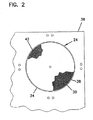
システム20で使用可能なエア・フィルタ装置24の一例を図2〜図4に示す。一般に、エア・フィルタ装置24は、第1の、または主フィルタ要素30と、予備フィルタとして働く第2のフィルタ要素32とを含む。用語「予備フィルタ」により、主要な主フィルタ要素30の上流に位置決めされた、ガス流から大きな粒子を除去する働きをする分離器を意味する。主フィルタ要素30を図2で見ることができ、予備フィルタ32を図3で見ることができる。主フィルタ要素30と予備フィルタ要素32は、好ましくは、チューブ・シート36の開口38内に取外し可能に取付可能なスリーブ部材34内部で固定される。一般に、空気流は、空気取込システム22を介して中に取り込まれ、まず予備フィルタ要素32を介し、次いで主フィルタ要素30を介して流れる。空気は、主フィルタ要素30を出た後、発電機28内に向けられる。
【0013】
C.主フィルタ要素
次に、図2、図5、および図7を参照すると、主フィルタ要素30は、直進通過流を可能にするように構成されている。用語「直進通過流」によって、流体が、フィルタ要素30を介して真っ直ぐに流れて、入口面40から入り、反対側に配設された出口面42から出て、入口面40から入る流体の流れの方向が出口面42から出る流体の流れの方向と同じであることを意味する。図2では、出口面42が概略的に示されていることを理解されたい。すなわち、面42の一部のみが縦溝を付けて図示されている。典型的なシステムでは、面42全体に縦溝が付いていることを理解されたい。
【0014】
フィルタ要素30は、第1の端部44と、反対側の第2の端部46とを有する。図2に示される構成では、第1の端部44は上流端部入口面40に対応し、第2の端部46は下流端部出口面42に対応する。直進通過流により、ガスは、第1の端部44内への空気流の方向が第2の端部46から出る空気流の方向と同じになるように、第1の端部44内に流れて、第2の端部46から出る。直進通過流パターンは、ガス流れ中の乱流の量を低減することができる。
【0015】
図16に注目する。図16は、主フィルタ要素30内で使用可能なある好ましい濾材の動作原理を示す概略斜視図である。図16に、縦溝付き構成の形での濾材が、参照番号50で概略的に表されている。好ましくは、縦溝付き構成50は、複数の縦溝54を有する波形の層52と、面シート56とを含む。図16の実施形態は、面シートの2つのセクションを、参照番号56A(波形層52の上に示される)と参照番号56B(波形層52の下に示される)で示す。通常、好ましい縦溝付き構成50は、下側面シート56Bに固定された波形層52を含む。この縦溝付き構成50をロール構成で使用するとき、通常は、下側面シート56Bが波形層52の上を覆うように丸められる。波形層52の上を覆う面シート56は、参照番号56Aで示されている。面シート56Aと56Bが同じシート56であることを理解されたい。
【0016】
このタイプの縦溝付き構成50を使用するとき、好ましくは、縦溝チャンバ58が交互の山60と谷62を形成する。谷62と山60が縦溝を2つの列に分割し、一方が他方の列に隣接して(図16では他方の列を覆って、または他方の列の上に)位置決めされている。図16に図示される特定の構成では、上側縦溝が、下流端で閉じた縦溝チャンバ64を形成し、上流端が閉じた縦溝チャンバ66が下側縦溝列を成す。縦溝チャンバ66は、縦溝シート52と第2の面シート56Bとの間の縦溝の上流端の一部を埋める第1の端部ビード68によって閉じられている。同様に、第2の端部ビード70が交互縦溝64の下流端を閉じる。
【0017】
縦溝付き構成50の形で構成された濾材を使用するとき、使用中に、空気など、濾過されていない流体が、陰付き矢印72によって示されるように縦溝チャンバ64に入る。縦溝チャンバ64は、開いた上流端74を有する。濾過されていない流体の流れは、下流端76が第2の端部ビード70によって閉じられるため、縦溝チャンバ64の下流端76を通過することができない。したがって、流体は、縦溝シート52または面シート56を介して進むように強いられる。濾過されていない流体が縦溝シート52または面シート56を通過するので、流体は浄化または濾過される。浄化された流体は陰の付いていない矢印78によって示される。次いで、流体は、閉じた上流端80を有する縦溝チャンバ66を通過して、開いた下流端を介して縦溝付き構成50から流れ出る。図示した構成では、濾過されていない流体は、縦溝付きシート52、上側面シート56A、または下側面シート56Bを介して、縦溝チャンバ66内に流れることができる。
【0018】
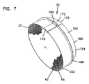
通常、図7に図示されるように、縦溝付き構成50は、ロールまたはコイル形状に巻かれる。様々な方法を使用して、縦溝付き構成50をコイル状にする、またはロールすることができる。縦溝付き構成50を中心コアの周りに巻き付けることができる。あるいは、縦溝付き構成50にコアがないようにすることもできる。再び、図2、図7、および図8を参照して、フィルタ要素30の断面形状が概して円形であることに留意されたい。断面は、他の実施形態では、長円形または「レーストラック形」など非円形であってもよい。「長円形」または「レーストラック形」によって、フィルタ要素が、湾曲した(いくつかの実施形態では半円形の)端部と、反対側の湾曲した(いくつかの実施形態では半円形の)端部とを画定することを意味する。また湾曲端部は、1対の直線セグメントによって接合される。
【0019】
濾材50は、ポリエステル合成濾材、セルロースからなる濾材、またはこれらのタイプの材料の組合せであってよい。使用可能なセルロース濾材の一例は、坪量が約45〜55Ibs/3000ft2(84.7g/m2)、例えば48〜54lbs/3000ft2、厚さが約0.005〜0.015インチ、例えば約0.010インチ(0.25mm)であり、フレーザ(frazier)浸透率が約20〜25ft/分、例えば約22ft/分(6.7m/分)であり、孔サイズが約55〜65ミクロン、例えば約62ミクロンであり、濡れ引張り強さが少なくとも約7Ibs/インチ、例えば8.5Ibs/インチ(3.9kg/インチ)であり、機械の破裂強度ウェット・オフが約15〜25psi、例えば約23psi(159kPa)である。セルロース濾材は、微細繊維、例えばサイズ(直径)が5ミクロン以下、いくつかの例ではサブミクロンの繊維で処理することができる。微細繊維を使用することが望まれる場合、微細繊維を濾材に適用するために様々な方法を利用することができる。いくつかのそのような手法は、例えば米国特許第5423892号、第32欄48〜60行で特徴付けられている。より具体的には、そのような方法は、本明細書に参照により組み込む米国特許第3878014号、第3676242号、第3841953号、および第3849241号に記載されている。代替方法は、ウルトラ・ウェブ(ULTRA−WEB、登録商標)の名称でドナルドソン カンパニー(Donaldson Company)によって企業秘密のもとで実施される従来の濾材の上に位置決めされた微細ポリマー繊維ウェブを備える企業秘密手法である。フィルタ要素の構成に関して、微細繊維を使用することが望まれる場合、どのように微細繊維を作成するか、および微細繊維を適用するために特定の方法のどれを使用するかについて特定の嗜好性はない。通常は、結果として得られる濾材構成が以下の特性を有するまで十分な微細繊維が適用される。すなわち、SAE J726Cに従ってSAE繊維ダストを使用して試験される、個々のテストが90%未満にならない平均99.5%の初期効率、およびSAE J726Cに従う平均99.98%の全体効率である。
【0020】
使用可能なフィルタ構成の例が米国特許第5820646号に記述されており、その特許を本明細書に参照により組み込む。
【0021】
D.予備フィルタ要素
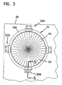
図3および図11〜図13に注目する。予備フィルタ要素32が例示されている。好ましくは、予備フィルタ要素32は、複数の個別のプリーツ(折り目)92を備えるプリーツ付き構成90である。プリーツ92はジグザグ形に構成される。図3、図11、および図13で見ることができるように、好ましい予備フィルタ要素32は概して円形の断面を有する。
【0022】
予備フィルタ要素32は、直進通過流を可能にするように構成されている。すなわち、空気は、予備フィルタ要素32を介して真っ直ぐに流れ、入口面94から入り、反対側に配設された出口面96から出て、入口面94から入る流体の流れの方向が出口面96から出る流体の流れの方向と同じである。
【0023】
いくつかの好ましい実施形態では、少なくとも15個のプリーツ92、80個以下のプリーツ92、および通常は30〜50個のプリーツ92が存在する。プリーツ付き構成90は、中心コア100の周りに中心合わせされたプリーツ92の形で折り畳まれた濾材98から作成される。使用可能なタイプの濾材98は、ファイバガラス、または別法として、エア・レイド濾材を含む。使用可能な濾材98の特定の特性としては、重量が2.7〜3.3oz/yd3(92〜112g/m3)であり、自由厚さ(すなわち0.002psi圧縮時の厚さ)が0.25〜0.40インチ(6.4〜10.2mm)であり、浸透率が少なくとも400ft/分(122m/分)であるウェブを形成するようにランダムに方向付けられたポリエステル繊維からなるドライ・レイド濾材が含まれる。
【0024】
好ましい予備フィルタ要素32は、少なくとも下流側96に、フィルタ支持部またはライナ102を含む。フィルタ支持部またはライナ102は、プラスチックまたは金属からなる発泡メッシュから構成することができる。ライナ102は図11では概略的に例示されていることに留意されたい。図11は、出口面96のある部分のみを覆っているライナ102を示している。これは、ライナ102が出口面96全体を覆っていることを表すものである。いくつかの代替実施形態では、入口面94もフィルタ支持部またはライナを有することができる。
【0025】
引き続き図11を参照すると、例示される予備フィルタ要素32では、円形プリーツ付き構成90の形状で予備フィルタ要素32を維持するために利用される接着剤104が存在する。特に、シーラント104は、円形状に成形した後にプリーツ付き構成90に塗布されるホットメルトのビード106であってよい。ビード106は固化し、プリーツ付き構成90を円形状に保持する助けとなる。
【0026】
一般に、予備フィルタ要素32は、スリーブ部材32内に取外し可能かつ再配置可能に取付可能である。スリーブ部材34を以下にさらに詳細に記述する。いくつかのシステムでは、予備フィルタ要素32は、スリーブ部材34の内壁に対して濾材98の先端部108を押しつぶす、または圧縮することによってスリーブ濾材34内部に保持される。すなわち、主フィルタ要素32は、好ましくは、スリーブ部材34の内径よりも大きな初期自由状態最外部寸法(この場合は直径)を有するように構成される。スリーブ部材34内部に配置されるとき、濾材98の先端部108が、スリーブ部材34の内壁とライナ102の端部との間で押しつぶされる、圧縮される、曲げられる、または粉砕される。
【0027】
予備フィルタ要素の代替実施形態は、図14および15に、一般に参照番号120で例示される。予備フィルタ要素120は、個別プリーツ124のプリーツ付き構成122を備える点で予備フィルタ要素32に類似している。予備フィルタ要素120は、予備フィルタ要素32とは異なる様式で組み立てられる。この実施形態では、予備フィルタ要素120は、濾材のシート126を一連のプリーツ124に折り畳むことによって構成される。これは、プリーツ付き濾材の概して長方形のシート128を形成する。シート128は、ポリウレタンを含む成形体内に挿入される。ポリウレタンが硬化されて、圧縮性ポリウレタンの中実長方形端部130を形成する。次いで、このパネル132を、予備フィルタ要素120の形に組み立てることができる。
【0028】
図15に注目する。図15は、パネル132を予備フィルタ要素120の形に組み立てる工程を例示する。端部130が摘み合わされて、コア134を形成する。次いで、端部プレート136、138が、互いに向けて矢印140、142の方向に移動される。この様式では、プリーツ付きパネル132が扇形に広げられて、円形予備フィルタ要素120を形成する。次いで、端部プレート136および138がクリップで互いに接合される。
【0029】
予備フィルタ要素120は、パネル132の形で保管し、エンド・ユーザに輸送することができるので好都合である。設置の直前に、パネル132を扇形に広げて、最終的な円形予備フィルタ要素120を形成することもできる。
【0030】
E.スリーブ部材およびクランプ・システム
本明細書における原理に従って構成される好ましいフィルタ装置24は、主フィルタ要素30に固定され、外接するスリーブ部材34を有する。
【0031】
一般に、スリーブ部材34は、空気取込システム22内で主要素30を定位置に保持するように働く。また、好ましいスリーブ部材34は、主要素30の上流で予備フィルタ要素32を定位置に保持する。
【0032】
図7〜図9に注目する。1つの好ましいスリーブ部材34が、主要素30を保持して例示されている。図7および図8で見ることができるように、スリーブ部材34は、好ましくは、主フィルタ要素の断面に合致する断面を有する。この場合、主フィルタ要素30は、概して円形の断面を有する。したがって、好ましいスリーブ部材34は概して円形の断面を有する。他の実施形態では、主要素30が異なる形状の断面を有することができることを理解されたい。その場合、スリーブ部材34が、フィルタ要素30の断面に合致する断面を有する。
【0033】
図5で見ることができるように、スリーブ部材34は、周囲リング152をもたらすある形に湾曲された周囲壁150を含む。壁150は、端部153(この場合には、主要素30の第2の端部46または出口面42と同じ高さである)から反対側の端部154に概して延在する長さを有する。スリーブ部材34は、好ましくは、主フィルタ要素30の軸方向長さの少なくとも30%に延在するように、主フィルタ要素30に関して方向付けられている。多くの典型的な構成では、スリーブ部材34は、主フィルタ要素30の軸方向長さの50%よりも多く延在する。実際、最も好ましい構成では、スリーブ部材34は、少なくとも、主フィルタ要素30の軸方向長さの全長(すなわち100%)に延在する。多くの典型的な適用例では、スリーブ部材34は、半径が少なくとも10インチ(25.4cm)、典型的には15〜30インチ(38.1〜76.2cm)であり、いくつかの例では50インチ以下である。
【0034】
スリーブ部材34は、好ましくは、意図されていない量の空気が主要素30を迂回するのを許すことなく、主フィルタ要素30をチューブ・シート36に固定することを可能にするように封止システムを用いて構成され、配置される。図3、図5、および図7〜図9に示される構成では、スリーブ部材34がシール部材圧力フランジ160を含む。フランジ160は、少なくとも部分的に、最も好ましい実施形態では完全に、スリーブ部材34の壁150に外接する。実際、最も好ましい実施形態では、フランジ160は、単一の押出体151として壁150と共に押出成形され、次いで主要素30の断面形状に合致する形状に湾曲される。シール部材圧力フランジ160は、シール部材162を支持するようにバックストップとして動作して、フランジ160とチューブ・シート36の間で、それらに対するシール164を作成する。好ましくは、フランジ160が、スリーブ部材34の壁150から半径方向に延在し、シール部材34に完全に外接する。フランジ160は、壁150から、シール部材162を支持するのに十分な距離だけ半径方向に延在する。一般に、この距離は少なくとも0.1インチ(0.25cm)、典型的には0.25〜2インチ(0.64〜5.1cm)であり、いくつかの実施形態では、10インチ(25.4cm)以下延在していてよい。
【0035】
上述したように、好ましくは、フランジ160と、スリーブ部材34の残りの部分とが、材料の単一部片として押し出される。多くの適用例で、スリーブ部材34およびフランジ160を、耐衝撃性ポリスチレンなどのプラスチックから押出しすることが簡便である。押出し後、延在するフランジ160を有する壁150が、所望の長さに切断される。延在するフランジ160を有する壁150は、主フィルタ要素30を支持するように湾曲形状に曲げられる。曲げは、冷間圧延プロセスによって達成することができる。押出体151の端部166、168は、この段階では一体に接合されていない。
【0036】
図10に注目する。図10は、当接する端部166、168を有する壁150を示す。押出体151の端部166、168が互いに押し合わされる前に、主フィルタ要素30がスリーブ部材34内部に設置される。いくつかの適用例では、主要素30は、その外壁に接着剤が塗布されている。あるいは、壁150の内面に沿って接着剤が塗布される。あるいは、主要素30の外面と、壁150の内面との両方に接着剤が塗布される。次いで、主要素30が、スリーブ部材34によって形成される開口170の内部に位置決めされる。次いで、クランプ機械が、当接係合するように端部166と端部168を互いに向けて押圧してジョイント174を形成する。次いで、パッチまたは維持クリップ172が、ジョイント174を覆って配置されて、スリーブ部材34をその最終形状(図に示される例では、概して円形状)で固定する。好ましくは、維持クリップ172が、スリーブ部材34に永久的に固定される。例えば、維持クリップ172を、超音波溶接によって壁150に固定することができる。
【0037】
維持クリップ172が、端部153と端部154の間でジョイント174に完全に重なるように構成されていることに留意されたい。すなわち、クリップ172は、端部153と概して同一平面、または同じ高さの端部176を有する。クリップは、端部154と概して同一平面、または同じ高さの端部178を有する。また、クリップ172が、フランジ160に重なり、係合する端部176、178間の突起180を有する。突起180の好ましい形状は、フランジ160の負の形状で内部ポケット182を画定するものである。図10に例示される実施形態では、突起180がU字形である。
【0038】
図5に注目する。フランジ160が第1および第2の対向する軸方向側面190、192を含むことがわかる。軸方向側面の一方、この場合は側面190が、シール部材162を支持する。シール部材162は、一般に、円形ガスケット194を備える。ガスケット194は、好ましくは、ガスケット194とフランジ160の側面190との間の接着剤によってフランジ160に固定される。ガスケット194はフランジ160上に位置決めされ、それにより壁150および主要素30に完全に外接する。
【0039】
また、図示した構成は、スリーブ部材34をチューブ・シート36にクランプするシステムを含む。図3、図5、および図6に例示される実施形態では、クランプ・システムが、複数のラッチまたはクランプ200を含む。スリーブ部材34がチューブ・シート36内に動作可能に設置されるとき、フランジ160とチューブ・シート36の間の良好な気密封止164を形成するように十分なラッチまたはクランプ200が存在すべきである。図3に示される実施形態では、4つのクランプ200が存在する。各クランプ200は、フランジ160の周縁に沿って半径方向で均等に離隔されている。他の実施形態では、4つよりも多いクランプ200、例えば6〜10個のクランプが存在する場合がある。いくつかの他の実施形態では、クランプ200が4つ未満の場合がある。
【0040】
図5および図6に注目する。図5では、クランプ200が断面で示されている。各クランプ200が、レバー202と、鼻部204と、プレート206とを含む。プレート206は、クランプ200をチューブ・シート36に固定するためのボルト212などの固定具を収容するための開口208、210を含む。
【0041】
鼻部204は、フランジ160に圧力を加え、チューブ・シート36に対してシール部材162を圧縮するように動作する。レバー202は、チューブ・シート36に向けて、またはそこから離れるように鼻部204を選択的に移動させるように動作する。例えば、チューブ・シート36内にフィルタ装置34を設置するとき、チューブ・シート36から離れる方向に鼻部204が移動するように、レバー202を人の親指または手によって押すことができる。これにより、システム設置者は、フランジ160を鼻部204とチューブ・シート36との間に位置決めすることができるようにフィルタ装置24を操作することができる。他の実施形態では、クランプ200を、例えば蝶ナットを使用して手で引張ることができる。
【0042】
F.方法
動作中、フィルタ装置24は以下のように使用される。システム20内で濾過すべき空気が、矢印23で取込システム22内に向けられる。空気はまず、予備フィルタ要素32を介して流れる。空気は、入口面94から入り、濾材126を通過して、出口面96を介して出る。予備フィルタ要素32は、取込空気から、より大きな粒子およびデブリを除去する。次に、空気が主フィルタ要素30に入る。空気は、入口面40から入り、縦溝付き構成50を通過し、出口面42から出る。ここから、空気が発電機28内に取り込まれる。
【0043】
典型的な動作では、水で約0.6〜1.6インチ(1.5〜4.1cm)のフィルタ装置24にわたる全体圧力降下がある。これは、主フィルタ要素30と予備フィルタ32の両方を含む。通常、予備フィルタ32のみにわたる圧力降下は水で約0.2〜0.6インチ(0.51〜1.5cm)であり、主要素30のみにわたる圧力降下は水で約0.4〜1インチ(1.02〜2.54cm)となっている。
【0044】
所定の動作期間後にフィルタ装置24を補修点検すべきである。主要素30よりも予備フィルタ要素32、120のほうを多く補修(すなわち除去および交換)する必要がある場合がある。予備フィルタ要素32、120を補修するために、予備フィルタ要素32、120は、そのプリーツ92、124が把持され、スリーブ部材34から除去される。これは、壁150の内面との摩擦係合から予備フィルタ32、120を引張ることによって行うことができる。次いで、古い予備フィルタ要素32、120を処分することができる。第2番目の新たな予備フィルタ要素32、120が提供される。予備フィルタ要素120は、パネル132の形であってもよい。あるいは、予備フィルタ要素32は、円形予備フィルタ32の形であってもよい。個別プリーツ124が扇形に広げられるようにパネル132が操作され、端部プリーツ136が端部プリーツ138に接合される。通常、次いで端部プリーツ136が端部プリーツ138にクリップされ、または結合されて、円形予備フィルタ要素120を形成する。次いで、新たな予備フィルタ要素32、120が、スリーブ部材34の内部に配置される。これは、壁150の内面に対してプリーツ付き濾材の先端部108を半径方向で圧縮することによって行うことができる。この摩擦係合は、予備フィルタ要素32、120を定位置に保持する助けをする。また、システム20の圧力が、予備フィルタ要素32、120をスリーブ部材34内で定位置に保持する助けをすることに留意されたい。
【0045】
時々、主要素30を補修点検する必要がある。通常、これは、圧力降下が水で約3〜4インチ(7.6〜10.2cm)になった後である。主要素30を補修するために、スリーブ部材34がチューブ・シート36から取り外される。これは、フランジ160とチューブ・シート36の間のシール34を壊すことによって行われる。シール164を壊すために、各クランプ200は、鼻部204がチューブ・シート36から離れるように移動されるように、それぞれのレバー202が押し下げられていることを必要とする場合がある。次いで、スリーブ部材34は、チューブ・シート36によって画定された開口38に沿ってチューブ・シート36から軸方向に摺動される。
【0046】
次いでスリーブ部材34と共に主要素30を処分することができる。好ましくは、主要素およびスリーブ部材34が、簡単に焼却することができるように、完全に非金属材料から構成される。好ましくは、主要素30およびスリーブ部材34が少なくとも95%、より典型的には少なくとも99%の非金属である。あるいは、主要素30をスリーブ部材34から取り外すこともでき、スリーブ部材34を再利用することもできる。
【0047】
次いで、新たな主要素30を有する第2番目の新たなスリーブ部材34が提供される。主フィルタ要素30を保持するスリーブ部材34は、チューブ・シート36の開口38内部に軸方向に配置される。各クランプ200は、レバー200を押すことによって操作されて、フランジ160を鼻部204とチューブ・シート36の壁との間に配置できるようにする。これは、フランジ160とチューブ・シート36との間に、それらに対してシール部材162を配置して、シール164を作成する。次いで、予備フィルタ要素32、120をスリーブ部材34内に設置することができる。
【0048】
上述した明細書、例、およびデータは、本発明の製造および使用を完全に説明するものであるが、他にも本発明の多くの実施形態が実現可能である。
【図面の簡単な説明】
【図1】 本明細書で開示する原理に従って構成されたエア・フィルタ装置を有するガス・タービン・システム用の空気取込システムの一実施形態の概略図である。
【図2】 主フィルタ要素を示し、エア・フィルタ装置がチューブ・シート内部に設置された一実施形態の概略前面図である。
【図3】 予備フィルタ要素を示し、図2に示されるエア・フィルタ装置の概略後面図である。
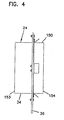
【図4】 チューブ・シート内に設置された図2および3のエア・フィルタ装置の概略側面図である。
【図5】 図3の線5−5に沿って取られた、図2〜図4のエア・フィルタ装置の概略部分拡大断面図である。
【図6】 チューブ・シート内で図2〜図4のエア・フィルタ装置を保持するために利用されるラッチの一実施形態の概略を拡大して示した平面図である。
【図7】 主フィルタ要素を示し、図2〜図4の、チューブ・シートから取り外されたエア・フィルタ装置の概略を示した斜視図である。
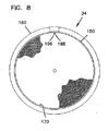
【図8】 主フィルタ要素を示し、図7のエア・フィルタ装置の概略を示した正面図である。
【図9】 図7および図8のエア・フィルタ装置の平面図である。
【図10】 図2〜図4および図7〜図9のエア・フィルタ装置内で利用されるフィルタ要素を保持するためのクリップおよびスリーブの概略を分解して示した斜視図である。
【図11】 図2〜4および図7〜図9のエア・フィルタ装置内で利用される予備フィルタの一実施形態の概略の平面図である。
【図12】 図11の予備フィルタの概略の側面図である。
【図13】 図11および図12の予備フィルタの概略の底面図である。
【図14】 組立中の、図2〜図4および図7〜図9のエア・フィルタ装置で利用される予備フィルタの別の実施形態の概略の平面図である。
【図15】 図14の予備フィルタを組み立てる別の工程の概略の平面図である。
【図16】 図2、図7、および図8に示される主フィルタ要素で使用可能な濾材の一部の一実施形態の概略の斜視図である。[0001]
(Technical field)
This disclosure describes filter configurations for filtering fluids such as gases and liquids. In particular, the present disclosure describes methods that are particularly useful in filter elements, prefilters, housings, and gas turbine systems.
[0002]
(background)
Gas turbine systems are useful for generating electricity. These types of systems are particularly advantageous in that they can be quickly configured. It is also desirable because it produces fewer hazardous emissions than coal or oil based turbine systems. Gas turbines use air for combustion. Because these types of systems have precision driven components, the air that is burned needs to be purified. In order to ensure clean air for this combustion, air filters are used to purify the air entrained in the gas turbine system. Prior art systems purify the intake air by using a series of panel filters. However, as the system became more sophisticated, cleaner air was required. This has resulted in increased costs.
[0003]
It would be desirable to improve the purification of air entrained in a gas turbine system.
[0004]
(Outline of disclosure)
In one aspect, this disclosure describes a filter device. Generally, the filter device includes a first filter element having first and second opposing ends, an axial length between the first and second ends, and a plurality of flutes. Each of the flutes has a first termination portion adjacent to the first end of the first filter element and a second termination portion adjacent to the second end of the first filter element. Some selected flutes are open at the first end portion and closed at the second end portion. Some selected flutes are closed at the first end portion and open at the second end portion. A sleeve member is fixed to the first filter element and circumscribed. The sleeve member is oriented with respect to the first filter element so as to extend at least 30% of the axial length of the first filter element. A seal member pressure flange at least partially circumscribes the sleeve member.
[0005]
In another aspect, a filtration system is described, a tube sheet having at least one through hole, a sleeve member removably and repositionably attached to the hole, and a flange at least partially circumscribing the sleeve member And a seal member that is compressed between the flange and the tube sheet and a first filter element secured within the sleeve member. The first filter element is preferably a straight flow passage system comprising fluted filter media.
[0006]
A preliminary filter element is also described. Preferably, the preliminary filter element is removably attached upstream of the main filter element within the sleeve member. A method for assembling the preliminary filter is described.
[0007]
A system for using the preferred filter device is described. A particularly useful system is a gas turbine system.
[0008]
Another aspect includes an operation and repair method. Preferred methods include configurations constructed according to the principles described herein.
[0009]
DETAILED DESCRIPTION OF THE INVENTION
A. 1 system to be used
The air purifier devices and configurations disclosed herein can be used in a variety of systems. FIG. 1 schematically shows one particular system, in this case a gas turbine system, at
[0010]
In FIG. 1, the air flow is illustrated by
[0011]
The air is purified in
[0012]
B. Outline of air filter device
An example of an
[0013]
C. Main filter element
Referring now to FIGS. 2, 5, and 7, the
[0014]
The
[0015]
Attention is directed to FIG. FIG. 16 is a schematic perspective view illustrating the operating principle of a preferred filter medium that can be used within the
[0016]
When using this type of
[0017]
When using a filter media configured in the form of a
[0018]
Typically, as shown in FIG. 7, the
[0019]
The
[0020]
An example of a filter configuration that can be used is described in US Pat. No. 5,820,646, which is incorporated herein by reference.
[0021]
D. Preliminary filter element
Attention is directed to FIG. 3 and FIGS. A
[0022]
The
[0023]
In some preferred embodiments, there are at least 15
[0024]
A
[0025]
With continued reference to FIG. 11, in the illustrated
[0026]
In general, the
[0027]
An alternative embodiment of the prefilter element is illustrated generally in FIG. The
[0028]
Attention is directed to FIG. FIG. 15 illustrates the process of assembling the
[0029]
Conveniently, the
[0030]
E. Sleeve member and clamping system
A
[0031]
In general, the
[0032]
Attention is directed to FIGS. One
[0033]
As can be seen in FIG. 5, the
[0034]
The
[0035]
As mentioned above, preferably the
[0036]
Attention is directed to FIG. FIG. 10 shows a
[0037]
Note that the retaining
[0038]
Attention is directed to FIG. It can be seen that the
[0039]
The illustrated configuration also includes a system for clamping the
[0040]
Attention is directed to FIGS. In FIG. 5, the
[0041]
The
[0042]
F. Method
In operation, the
[0043]
In typical operation, there is an overall pressure drop across the
[0044]
The
[0045]
From time to time, it is necessary to repair and inspect the
[0046]
The
[0047]
A second
[0048]
While the above specification, examples and data provide a complete description of the manufacture and use of the invention, many other embodiments of the invention are possible.
[Brief description of the drawings]
FIG. 1 is a schematic diagram of one embodiment of an air intake system for a gas turbine system having an air filter device constructed in accordance with the principles disclosed herein.
FIG. 2 is a schematic front view of an embodiment showing the main filter element and an air filter device installed inside the tube seat.
FIG. 3 is a schematic rear view of the air filter device shown in FIG. 2 showing a pre-filter element.
4 is a schematic side view of the air filter device of FIGS. 2 and 3 installed in a tube sheet. FIG.
5 is a schematic partial enlarged cross-sectional view of the air filter device of FIGS. 2-4 taken along line 5-5 of FIG. 3;
FIG. 6 is an enlarged plan view schematically showing one embodiment of a latch used to hold the air filter device of FIGS. 2 to 4 in a tube sheet.
7 is a perspective view showing the main filter element and schematically showing the air filter device of FIGS. 2 to 4 removed from the tube sheet. FIG.
8 is a front view showing the main filter element and schematically showing the air filter device of FIG. 7. FIG.
9 is a plan view of the air filter device of FIGS. 7 and 8. FIG.
10 is an exploded perspective view schematically showing a clip and a sleeve for holding a filter element used in the air filter device of FIGS. 2 to 4 and FIGS. 7 to 9; FIG.
11 is a schematic plan view of one embodiment of a pre-filter utilized within the air filter apparatus of FIGS. 2-4 and FIGS. 7-9. FIG.
12 is a schematic side view of the preliminary filter of FIG.
13 is a schematic bottom view of the preliminary filter of FIGS. 11 and 12. FIG.
14 is a schematic plan view of another embodiment of a pre-filter utilized in the air filter apparatus of FIGS. 2-4 and FIGS. 7-9 during assembly. FIG.
FIG. 15 is a schematic plan view of another process for assembling the preliminary filter of FIG. 14;
16 is a schematic perspective view of one embodiment of a portion of a filter media that can be used with the main filter element shown in FIGS. 2, 7, and 8. FIG.
Claims (11)
(a)前記フィルタ装置は、セルロース、ポリエステル又はそれらの混合物から作成された柔軟なフィルタ媒体を含む第1のフィルタ要素を備え、前記第1のフィルタ要素は、互いに対向する第1および第2の端部と、前記第1および第2の端部間の軸方向長さと、縦溝構造を形成する複数の縦溝とを有し、
(i)前記縦溝のそれぞれは、前記第1のフィルタ要素の第1の端部に隣接する第1の終端部分と、前記第1のフィルタ要素の第2の端部に隣接する第2の終端部分とを有し、
(A)前記縦溝の選択されたいくつかが、前記第1の終端部分で開き前記第2の終端部分で閉じており、前記縦溝の選択された他のいくつかが、前記第1の終端部分で閉じ前記第2の終端部分で開いており、
(ii)前記第1のフィルタ要素は、互いに対向する湾曲端部をセグメントで接続した非円形の横断面を有し、
(b)前記フィルタ装置は、前記第1のフィルタ要素に外接するスリーブ部材を備え、
(i)前記スリーブ部材は、前記第1のフィルタ要素を受け入れる大きさの横断面を有し、
(ii)前記スリーブ部材は、前記第1のフィルタ要素の軸方向長さの50%以上に亙り延設される壁を含み、
(c)前記フィルタ装置は、前記スリーブ部材から半径方向に延設され、前記スリーブ部材を完全に取り囲むフランジを備え、
(i)前記フランジは、互いに対向する第1の軸方向面と第2の軸方向面とを含み、
(ii)前記フランジは、前記スリーブ部材の前記壁から、少なくとも2.54mmの距離だけ半径方向に延設され、
(iii)前記フランジは、前記第1のフィルタ要素の横断面の形状に合致する形状に曲げられており、
(d)前記フィルタ装置は、前記フランジの前記第1の軸方向面に対向して配置されるシール部材を備え、
(e)前記フィルタ装置は、濾過システム内に装填されたときに、前記フランジに対して圧力を印加し、前記シール部材を圧縮して前記フランジと前記濾過システムとの間にシールを形成するシステムを備え、
(i)前記フランジが前記シール部材を支持する支持部材として機能する、ことを特徴とするフィルタ装置。A filter device,
(A) the filter device comprises a first filter element comprising a flexible filter medium made from cellulose, polyester or a mixture thereof, the first filter element being first and second facing each other; An end, an axial length between the first and second ends, and a plurality of longitudinal grooves forming a longitudinal groove structure;
(I) each of the longitudinal grooves includes a first termination portion adjacent to the first end of the first filter element and a second end adjacent to the second end of the first filter element; A terminal portion,
(A) some selected of the flutes open at the first end portion and close at the second end portion, and some other selected of the flutes are the first end portion Closed at the end portion and open at the second end portion;
(Ii) the first filter element has a non-circular cross section in which curved ends facing each other are connected by a segment;
(B) the filter device includes a sleeve member circumscribing the first filter element;
(I) the sleeve member has a cross section sized to receive the first filter element;
(Ii) The sleeve member includes a wall extending over 50% or more of the axial length of the first filter element;
(C) the filter device includes a flange extending radially from the sleeve member and completely surrounding the sleeve member;
(I) the flange includes a first axial surface and a second axial surface facing each other;
(Ii) the flange extends radially from the wall of the sleeve member by a distance of at least 2.54 mm;
(Iii) the flange is bent into a shape that matches the shape of the cross section of the first filter element;
(D) The filter device includes a seal member disposed to face the first axial surface of the flange,
(E) When the filter device is loaded in a filtration system, it applies pressure to the flange and compresses the seal member to form a seal between the flange and the filtration system. With
(I) The filter device, wherein the flange functions as a support member that supports the seal member.
(a)前記フィルタ装置は、セルロース、ポリエステル又はそれらの混合物から作成された柔軟なフィルタ媒体を含む第1のフィルタ要素を備え、前記第1のフィルタ要素は、互いに対向する第1および第2の端部と、前記第1および第2の端部間の軸方向長さと、縦溝構造を形成する複数の縦溝とを有し、
(i)前記縦溝のそれぞれは、前記第1のフィルタ要素の第1の端部に隣接する第1の終端部分と、前記第1のフィルタ要素の第2の端部に隣接する第2の終端部分とを有し、
(A)前記縦溝の選択されたいくつかが、前記第1の終端部分で開き前記第2の終端部分で閉じており、前記縦溝の選択された他のいくつかが、前記第1の終端部分で閉じ前記第2の終端部分で開いており、
(ii)前記第1のフィルタ要素は、互いに対向する湾曲端部をセグメントで接合した競技場走路形状の横断面を有し、
(b)前記フィルタ装置は、前記第1のフィルタ要素に外接するスリーブ部材を備え、
(i)前記スリーブ部材は、前記第1のフィルタ要素を受け入れる大きさの横断面を有し、
(ii)前記スリーブ部材は、前記第1のフィルタ要素の軸方向長さの50%以上に亙り延設される壁を含み、
(c)前記フィルタ装置は、前記スリーブ部材から半径方向に延設され、前記スリーブ部材を完全に取り囲むフランジを備え、
(i)前記フランジは、互いに対向する第1の軸方向面と第2の軸方向面とを含み、
(ii)前記フランジは、前記スリーブ部材の前記壁から、少なくとも2.54mmの距離だけ半径方向に延設され、
(iii)前記フランジは、前記第1のフィルタ要素の横断面の形状に合致する形状に曲げられており、
(d)前記フィルタ装置は、前記フランジの前記第1の軸方向面に対向して配置されるシール部材を備え、
(e)前記フィルタ装置は、濾過システム内に装填されたときに、前記フランジに対して圧力を印加し、前記シール部材を圧縮して前記フランジと前記濾過システムとの間にシールを形成するシステムを備え、
(i)前記フランジが前記シール部材を支持する支持部材として機能する、
ことを特徴とするフィルタ装置。 A filter device,
(A) the filter device comprises a first filter element comprising a flexible filter medium made from cellulose, polyester or a mixture thereof, the first filter element being first and second facing each other; An end, an axial length between the first and second ends, and a plurality of longitudinal grooves forming a longitudinal groove structure;
(I) each of the longitudinal grooves includes a first termination portion adjacent to the first end of the first filter element and a second end adjacent to the second end of the first filter element; A terminal portion,
(A) some selected of the flutes open at the first end portion and close at the second end portion, and some other selected of the flutes are the first end portion Closed at the end portion and open at the second end portion;
(Ii) said first filter element, have a cross-section of the stadium track shape joined by segments curved ends that face each other,
(B) the filter device includes a sleeve member circumscribing the first filter element;
(I) the sleeve member has a cross section sized to receive the first filter element;
(Ii) The sleeve member includes a wall extending over 50% or more of the axial length of the first filter element;
(C) the filter device includes a flange extending radially from the sleeve member and completely surrounding the sleeve member;
(I) the flange includes a first axial surface and a second axial surface facing each other;
(Ii) the flange extends radially from the wall of the sleeve member by a distance of at least 2.54 mm;
(Iii) the flange is bent into a shape that matches the shape of the cross section of the first filter element;
(D) The filter device includes a seal member disposed to face the first axial surface of the flange,
(E) When the filter device is loaded in a filtration system, it applies pressure to the flange and compresses the seal member to form a seal between the flange and the filtration system. With
(I) The flange functions as a support member that supports the seal member;
And a filter device .
(a)前記装填方法は、セルロース、ポリエステル又はそれらの混合物から作成された柔軟なフィルタ媒体を含む第1のフィルタ要素を提供する工程を含み、前記第1のフィルタ要素は、互いに対向する第1および第2の端部と、前記第1および第2の端部間の軸方向長さと、縦溝構造を形成する複数の縦溝とを有し、
(i)前記縦溝のそれぞれは、前記第1のフィルタ要素の第1の端部に隣接する第1の終端部分と、前記第1のフィルタ要素の第2の端部に隣接する第2の終端部分とを有し、
(A)前記縦溝の選択されたいくつかが、前記第1の終端部分で開き前記第2の終端部分で閉じており、前記縦溝の選択された他のいくつかが、前記第1の終端部分で閉じ前記第2の終端部分で開いており、
(B)前記第1のフィルタ要素は、互いに対向する湾曲端部をセグメントで接続した非円形の横断面を有し、
(ii)スリーブ部材が、前記第1のフィルタ要素に外接し、
(A)前記スリーブ部材は、前記第1のフィルタ要素を受け入れる大きさの横断面を有し、
(B)前記スリーブ部材は、前記第1のフィルタ要素の軸方向長さの50%以上に亙り延設される壁を含み、
(iii)フランジが、前記スリーブ部材から半径方向に延設されて、前記スリーブ部材を完全に取り囲み、
(A)前記フランジは、互いに対向する第1の軸方向面と第2の軸方向面とを含み、
(B)前記フランジは、前記スリーブ部材の前記壁から、少なくとも2.54mmの距離だけ半径方向に延設され、
(C)前記フランジは、前記第1のフィルタ要素の横断面の形状に合致する形状に曲げられており、
(b)前記装填方法は、前記フランジに圧力を印加するシステムを用いて、前記フランジの前記第1の軸方向面に対してシール部材を圧縮することにより、前記フランジと濾過システムの表面の間にシールを形成する工程を備える、
ことを特徴とする装填方法。A filter device loading method comprising:
(A) the loading method includes providing a first filter element comprising a flexible filter medium made from cellulose, polyester or a mixture thereof, wherein the first filter elements are first opposite each other. And a second end, an axial length between the first and second ends, and a plurality of longitudinal grooves forming a longitudinal groove structure,
(I) each of the longitudinal grooves includes a first termination portion adjacent to the first end of the first filter element and a second end adjacent to the second end of the first filter element; A terminal portion,
(A) some selected of the flutes open at the first end portion and close at the second end portion, and some other selected of the flutes are the first end portion Closed at the end portion and open at the second end portion;
(B) the first filter element has a non-circular cross section in which curved ends facing each other are connected by a segment;
(Ii) a sleeve member circumscribes the first filter element;
(A) the sleeve member has a cross section sized to receive the first filter element;
(B) The sleeve member includes a wall extending over 50% or more of the axial length of the first filter element,
(Iii) a flange extends radially from the sleeve member to completely surround the sleeve member;
(A) the flange includes a first axial surface and a second axial surface facing each other;
(B) the flange extends radially from the wall of the sleeve member by a distance of at least 2.54 mm;
(C) the flange is bent into a shape that matches the shape of the cross section of the first filter element;
(B) The loading method uses a system that applies pressure to the flange to compress the seal member against the first axial surface of the flange, thereby providing a clearance between the flange and the surface of the filtration system. Comprising the step of forming a seal on
A loading method characterized by the above.
(a)前記装填方法は、セルロース、ポリエステル又はそれらの混合物から作成された柔軟なフィルタ媒体を含む第1のフィルタ要素を提供する工程を含み、前記第1のフィルタ要素は、互いに対向する第1および第2の端部と、前記第1および第2の端部間の軸方向長さと、縦溝構造を形成する複数の縦溝とを有し、
(i)前記縦溝のそれぞれは、前記第1のフィルタ要素の第1の端部に隣接する第1の終端部分と、前記第1のフィルタ要素の第2の端部に隣接する第2の終端部分とを有し、
(A)前記縦溝の選択されたいくつかが、前記第1の終端部分で開き前記第2の終端部分で閉じており、前記縦溝の選択された他のいくつかが、前記第1の終端部分で閉じ前記第2の終端部分で開いており、
(B)前記第1のフィルタ要素は、互いに対向する湾曲端部をセグメントで接合した競技場走路形状の横断面を有し、
(ii)スリーブ部材が、前記第1のフィルタ要素に外接し、
(A)前記スリーブ部材は、前記第1のフィルタ要素を受け入れる大きさの横断面を有し、
(B)前記スリーブ部材は、前記第1のフィルタ要素の軸方向長さの50%以上に亙り延設される壁を含み、
(iii)フランジが、前記スリーブ部材から半径方向に延設されて、前記スリーブ部材を完全に取り囲み、
(A)前記フランジは、互いに対向する第1の軸方向面と第2の軸方向面とを含み、
(B)前記フランジは、前記スリーブ部材の前記壁から、少なくとも2.54mmの距離だけ半径方向に延設され、
(C)前記フランジは、前記第1のフィルタ要素の横断面の形状に合致する形状に曲げられており、
(b)前記装填方法は、前記フランジに圧力を印加するシステムを用いて、前記フランジの前記第1の軸方向面に対してシール部材を圧縮することにより、前記フランジと濾過システムの表面の間にシールを形成する工程を備える、
ことを特徴とする装填方法。 A filter device loading method comprising:
(A) the loading method includes providing a first filter element comprising a flexible filter medium made from cellulose, polyester or a mixture thereof, wherein the first filter elements are first opposite each other. And a second end, an axial length between the first and second ends, and a plurality of longitudinal grooves forming a longitudinal groove structure,
(I) each of the longitudinal grooves includes a first termination portion adjacent to the first end of the first filter element and a second end adjacent to the second end of the first filter element; A terminal portion,
(A) some selected of the flutes open at the first end portion and close at the second end portion, and some other selected of the flutes are the first end portion Closed at the end portion and open at the second end portion;
(B) said first filter element, have a cross-section of the stadium track shape joined by segments curved ends that face each other,
(Ii) a sleeve member circumscribes the first filter element;
(A) the sleeve member has a cross section sized to receive the first filter element;
(B) The sleeve member includes a wall extending over 50% or more of the axial length of the first filter element,
(Iii) a flange extends radially from the sleeve member to completely surround the sleeve member;
(A) the flange includes a first axial surface and a second axial surface facing each other;
(B) the flange extends radially from the wall of the sleeve member by a distance of at least 2.54 mm;
(C) the flange is bent into a shape that matches the shape of the cross section of the first filter element;
(B) The loading method uses a system that applies pressure to the flange to compress the seal member against the first axial surface of the flange, thereby providing a clearance between the flange and the surface of the filtration system. Comprising the step of forming a seal on
A loading method characterized by the above.
Applications Claiming Priority (3)
| Application Number | Priority Date | Filing Date | Title |
|---|---|---|---|
| US09/437,867 US6348085B1 (en) | 1999-11-10 | 1999-11-10 | Filter arrangement and methods |
| US09/437,867 | 1999-11-10 | ||
| PCT/US2000/042131 WO2001034278A1 (en) | 1999-11-10 | 2000-11-09 | Filter arrangement and methods |
Publications (3)
| Publication Number | Publication Date |
|---|---|
| JP2003513776A JP2003513776A (en) | 2003-04-15 |
| JP2003513776A5 JP2003513776A5 (en) | 2008-01-17 |
| JP4738690B2 true JP4738690B2 (en) | 2011-08-03 |
Family
ID=23738260
Family Applications (1)
| Application Number | Title | Priority Date | Filing Date |
|---|---|---|---|
| JP2001536270A Expired - Lifetime JP4738690B2 (en) | 1999-11-10 | 2000-11-09 | Filter apparatus and method |
Country Status (13)
| Country | Link |
|---|---|
| US (5) | US6348085B1 (en) |
| EP (1) | EP1231999A1 (en) |
| JP (1) | JP4738690B2 (en) |
| KR (1) | KR20020049042A (en) |
| CN (2) | CN1409649A (en) |
| AU (1) | AU780292B2 (en) |
| BR (1) | BR0015458A (en) |
| CA (1) | CA2390663A1 (en) |
| CZ (1) | CZ20021599A3 (en) |
| HK (1) | HK1051010A1 (en) |
| MX (1) | MXPA02004737A (en) |
| RU (1) | RU2002113452A (en) |
| WO (1) | WO2001034278A1 (en) |
Families Citing this family (138)
| Publication number | Priority date | Publication date | Assignee | Title |
|---|---|---|---|---|
| SE512980C2 (en) * | 1998-10-22 | 2000-06-12 | Flaekt Ab | Filter device for air ducts or air handling units |
| US6190432B1 (en) | 1999-02-26 | 2001-02-20 | Donaldson Company, Inc. | Filter arrangement; sealing system; and methods |
| DE60006789T3 (en) * | 1999-02-26 | 2012-03-22 | Donaldson Co., Inc. | SEALING SYSTEM FOR FILTERS |
| US8449638B2 (en) | 1999-11-05 | 2013-05-28 | Donaldson Company, Inc. | Filter element, air cleaner, and methods |
| US6348084B1 (en) | 1999-11-05 | 2002-02-19 | Donaldson Company, Inc. | Filter element, air cleaner, and methods |
| US6348085B1 (en) * | 1999-11-10 | 2002-02-19 | Donaldson Company, Inc. | Filter arrangement and methods |
| US6673136B2 (en) * | 2000-09-05 | 2004-01-06 | Donaldson Company, Inc. | Air filtration arrangements having fluted media constructions and methods |
| JP4640895B2 (en) * | 2001-03-29 | 2011-03-02 | 日本無機株式会社 | High performance filter for gas turbine intake and gas turbine intake filter unit using the same |
| US6610126B2 (en) | 2001-06-06 | 2003-08-26 | Donaldson Company, Inc. | Filter element having sealing members and methods |
| US6517598B2 (en) * | 2001-06-06 | 2003-02-11 | Donaldson Company, Inc. | Filter element having flange and methods |
| US6852141B2 (en) * | 2001-06-06 | 2005-02-08 | Donaldson Company, Inc. | Filter element having center piece and methods |
| US6966940B2 (en) * | 2002-04-04 | 2005-11-22 | Donaldson Company, Inc. | Air filter cartridge |
| ATE535295T1 (en) | 2002-05-09 | 2011-12-15 | Donaldson Co Inc | AIR FILTER WITH CORRUPTED FILTER MEDIUM |
| US6824582B2 (en) * | 2002-12-13 | 2004-11-30 | Westar Corporation | Filter system for turbine engine |
| CA2516007C (en) | 2003-02-11 | 2014-09-02 | Donaldson Company, Inc. | Air cleaner arrangements; serviceable filter elements; and, methods |
| EP1608453B1 (en) | 2003-03-18 | 2010-06-02 | Donaldson Company, Inc. | Improved process for coiling z-filter media |
| EP2316557B1 (en) * | 2003-11-12 | 2017-04-26 | Donaldson Company, Inc. | Air filter with slide mount for filtering element |
| CN101693158B (en) * | 2003-12-22 | 2013-02-20 | 唐纳森公司 | Filter element comprising a seal arrangement and method for making the same |
| US20090266041A1 (en) * | 2003-12-22 | 2009-10-29 | Donaldson Company, Inc. | Seal arrangement for filter element; Filter element assembly; and, methods |
| WO2005079954A1 (en) | 2004-02-17 | 2005-09-01 | Donaldson Company, Inc. | Air cleaner arrangements; serviceable filter elements; and, methods |
| US7048500B2 (en) * | 2004-03-01 | 2006-05-23 | Donaldson Company, Inc. | Silencer for ventilation system and methods |
| BRPI0507946A (en) | 2004-03-24 | 2007-07-24 | Donaldson Co Inc | filter elements, air filter, assembly and methods |
| GB0409548D0 (en) * | 2004-04-29 | 2004-06-02 | King S College London | Robotic hand |
| BRPI0510467B8 (en) | 2004-04-30 | 2016-10-11 | Donaldson Co Inc | Air filter cartridge arrangement removably installed in an air cleaning housing during use and air filter assembly. |
| US7905936B2 (en) * | 2004-04-30 | 2011-03-15 | Donaldson Company, Inc. | Filter arrangements; housing; assemblies; and, methods |
| ES2355832T3 (en) | 2004-06-08 | 2011-03-31 | Donaldson Company, Inc. | FILTER MEDIA PACKAGING PROVISION Z. |
| WO2005123222A1 (en) * | 2004-06-14 | 2005-12-29 | Donaldson Company, Inc. | Air filter arrangement; assembly; and, methods |
| US8048188B2 (en) | 2004-06-18 | 2011-11-01 | Donaldson Company, Inc. | Air cleaner arrangements; serviceable filter cartridge; and, methods |
| EP2239039B1 (en) | 2004-08-06 | 2021-10-06 | Donaldson Company, Inc. | Air filter cartridge |
| DE102005010443A1 (en) * | 2004-09-21 | 2006-03-23 | Mann + Hummel Gmbh | filter element |
| US20060090431A1 (en) * | 2004-11-02 | 2006-05-04 | Baldwin Filters, Inc. | Filter assembly with combination filter element |
| US7931725B2 (en) | 2004-11-02 | 2011-04-26 | Baldwin Filters, Inc. | Fluted filter apparatus |
| US7318851B2 (en) | 2004-11-02 | 2008-01-15 | Baldwin Filters, Inc. | Filter element |
| US20070186528A1 (en) * | 2006-02-15 | 2007-08-16 | Baldwin Filters, Inc. | Fluted filter apparatus |
| US8042694B2 (en) * | 2004-11-02 | 2011-10-25 | Baldwin Filters, Inc. | Gathered filter media for an air filter and method of making same |
| US20060091084A1 (en) * | 2004-11-02 | 2006-05-04 | Baldwin Filters, Inc. | Fluted filter media with intermediate flow restriction and method of making same |
| US20060091064A1 (en) * | 2004-11-02 | 2006-05-04 | Baldwin Filters, Inc. | Filter apparatus with separable seal support frame |
| US20110197556A1 (en) * | 2004-11-02 | 2011-08-18 | Baldwin Filters, Inc. | Filter element |
| US20060091061A1 (en) * | 2004-11-02 | 2006-05-04 | Baldwin Filters, Inc. | Filter assembly with sealing system |
| US7909954B2 (en) * | 2004-11-03 | 2011-03-22 | Baldwin Filters, Inc. | Method and apparatus for winding a filter media pack |
| US7255300B2 (en) | 2004-11-03 | 2007-08-14 | Baldwin Filters, Inc. | Method and apparatus for winding a filter media pack |
| US20060107631A1 (en) * | 2004-11-24 | 2006-05-25 | San Ford Machinery Co., Ltd. | Dust-bag previously pressing hook for a dust collecting machine |
| US7297173B2 (en) * | 2004-11-30 | 2007-11-20 | Donaldson Company, Inc. | Gas turbine air intake system with bypass arrangement and methods |
| US20060137312A1 (en) * | 2004-12-29 | 2006-06-29 | San Ford Machinery Co., Ltd. | Positioning device for the dust-collecting bag of a dust-collecting machine |
| EP1838414B1 (en) * | 2005-01-13 | 2012-03-07 | Donaldson Company, Inc. | Air filter arrangement |
| CN102512889B (en) * | 2005-01-13 | 2015-11-25 | 唐纳森公司 | Air filter cartridge and air cleaner assembly |
| US7520913B2 (en) | 2005-02-04 | 2009-04-21 | Donaldson Company, Inc. | Non-cylindrical filter elements, and methods |
| US8083825B2 (en) * | 2005-02-28 | 2011-12-27 | Donaldson Company, Inc. | Filter arrangement and method |
| KR101463630B1 (en) | 2005-10-11 | 2014-11-19 | 도날드슨 컴파니, 인코포레이티드 | Air filter arrangement, assembly, and methods |
| DE102005051503A1 (en) * | 2005-10-26 | 2007-05-03 | Mann + Hummel Gmbh | Extruded seal |
| US8409316B2 (en) | 2005-11-09 | 2013-04-02 | Donaldson Company, Inc. | Seal arrangement for filter element; filter element assembly; and, methods |
| DE102006001126A1 (en) | 2006-01-09 | 2007-07-12 | Kettenbach Gmbh & Co. Kg | Dental impression compounds, hardened products prepared therefrom and use of surfactants for the production of dental impression compounds |
| US7708797B2 (en) | 2006-01-20 | 2010-05-04 | Donaldson Company, Inc. | Air cleaner configured for receipt of various sized filter cartridges; components thereof; and, methods |
| US7753982B2 (en) | 2006-02-17 | 2010-07-13 | Baldwin Filters, Inc. | Filter with drained jacket, seal indicator/lock means, and seal baffle |
| US7625419B2 (en) | 2006-05-10 | 2009-12-01 | Donaldson Company, Inc. | Air filter arrangement; assembly; and, methods |
| DE102006028161A1 (en) * | 2006-06-16 | 2007-12-27 | Mann + Hummel Gmbh | Compact filter element with knock-out protection |
| CN103084021B (en) * | 2006-06-22 | 2015-07-01 | 唐纳森公司 | Air cleaner arrangements, parts and method thereof |
| US7713321B2 (en) * | 2006-06-22 | 2010-05-11 | Donaldson Company, Inc. | Air cleaner arrangements; components thereof; and, methods |
| WO2008045326A2 (en) | 2006-10-06 | 2008-04-17 | Donaldson Company, Inc. | Air cleaner, replaceable filter cartridges, and methods |
| US7588619B2 (en) | 2006-11-28 | 2009-09-15 | Wix Filtration Corp. | Cross-flow filter media and filter assembly |
| CN101541395B (en) * | 2006-11-30 | 2013-04-10 | 唐纳森公司 | System configuration of pulsed cleaned panel-style filter elements and methods |
| EP2091630A1 (en) * | 2006-11-30 | 2009-08-26 | Donaldson Company, Inc. | Filter apparatus configuration of pulsed cleaned panel-style filters and methods |
| US10040020B2 (en) | 2006-12-06 | 2018-08-07 | Baldwin Filters, Inc. | Fluid filter apparatus having filter media wound about a winding frame |
| US9757676B2 (en) * | 2006-12-06 | 2017-09-12 | Baldwin Filters, Inc. | Method and apparatus for winding a filter element |
| CN102743937B (en) | 2007-02-02 | 2015-09-16 | 唐纳森公司 | Air filtration media bag, filter element, air filtration media and method |
| CN101646479B (en) * | 2007-02-26 | 2012-10-17 | 唐纳森公司 | Air filter arrangement |
| EP2829310A1 (en) | 2007-06-26 | 2015-01-28 | Donaldson Company, Inc. | Filtration media pack |
| EP2188036A4 (en) * | 2007-07-13 | 2011-08-17 | Donaldson Co Inc | Media for removal of organic compounds |
| US8066791B2 (en) | 2007-07-20 | 2011-11-29 | Donaldson Company, Inc. | Air cleaner arrangements with internal and external support for cartridge; components; and, methods |
| EP2190554B1 (en) | 2007-09-07 | 2013-01-09 | Donaldson Company, Inc. | Air filter assembly |
| US20090100918A1 (en) * | 2007-09-26 | 2009-04-23 | United Technologies Corp. | Systems and Methods for Testing Gas Turbine Engines |
| US9545593B2 (en) * | 2007-11-01 | 2017-01-17 | Baldwin Filters, Inc. | Winding core pressure relief for fluted filter |
| CN103721481B (en) | 2007-11-15 | 2016-01-06 | 唐纳森公司 | Air filter arrangement, assembly and method |
| MX2010008530A (en) * | 2008-02-04 | 2010-08-30 | Donaldson Co Inc | Method and apparatus for forming fluted filtration media. |
| US8545585B2 (en) * | 2008-02-25 | 2013-10-01 | Donaldson Company, Inc. | Filter element for pulse cleaning and methods |
| US20090249957A1 (en) * | 2008-04-04 | 2009-10-08 | Lackey Sr Robert W | Two Stage Air Filter |
| US8048187B2 (en) | 2008-06-30 | 2011-11-01 | Baldwin Filters, Inc. | Filter frame attachment and fluted filter having same |
| US7959703B2 (en) | 2008-06-30 | 2011-06-14 | Baldwin Filters, Inc. | Fluted filter with integrated frame |
| US8414639B2 (en) * | 2008-07-08 | 2013-04-09 | Boston Scientific Scimed, Inc. | Closed-cell flexible stent hybrid |
| CA2995098C (en) | 2008-07-22 | 2021-01-05 | Donaldson Company, Inc. | Air cleaner assembly and components therefor |
| JP5757868B2 (en) | 2008-07-25 | 2015-08-05 | ドナルドソン カンパニー,インコーポレイティド | Air filtration media pack, filter element, air filtration media and method (fluided filtration media, media pack, filter element and fluid filtration method) |
| EP2323749A1 (en) | 2008-08-06 | 2011-05-25 | Donaldson Company, Inc. | Z-media having flute closures, methods and apparatus |
| US8088190B2 (en) * | 2008-08-21 | 2012-01-03 | Mann + Hummel Gmbh | Unitary filter element with integral pre-separation |
| US8317890B2 (en) | 2008-08-29 | 2012-11-27 | Donaldson Company, Inc. | Filter assembly; components therefor; and, methods |
| US8961637B2 (en) | 2009-01-14 | 2015-02-24 | Donaldson Company, Inc. | Filter element; components thereof; and methods |
| US8506668B2 (en) * | 2009-03-30 | 2013-08-13 | Baldwin Filters, Inc. | Fluted filter with axial seal |
| US8192623B2 (en) | 2009-04-01 | 2012-06-05 | Wix Filtration Corp Llc | Filter structure |
| US8753414B2 (en) | 2009-04-02 | 2014-06-17 | W. L. Gore & Associates, Inc. | Filter assembly and mounting flange extension for gas turbine filter assembly |
| US8061530B2 (en) | 2009-04-09 | 2011-11-22 | Cummins Filtration Ip, Inc. | Filtration sealing system |
| WO2011017352A2 (en) | 2009-08-03 | 2011-02-10 | Donaldson Company, Inc. | Method and apparatus for forming fluted filtration media having tapered flutes |
| US9174160B2 (en) * | 2009-08-19 | 2015-11-03 | Baldwin Filters, Inc. | Collapsible core, filter, and method |
| EP2482955B1 (en) | 2009-10-02 | 2013-08-28 | Donaldson Company, Inc. | Filter cartridge with centerboard, dust collectors, and methods |
| CN102574043B (en) * | 2009-10-14 | 2015-04-29 | 唐纳森公司 | Filter cartridge with seal member and methods |
| EP3950092B1 (en) | 2010-01-25 | 2023-05-10 | Donaldson Company, Inc. | Pleated filtration media having tapered flutes |
| WO2011115973A2 (en) | 2010-03-17 | 2011-09-22 | Baldwin Filters, Inc. | Fluid filter |
| WO2011115979A2 (en) | 2010-03-17 | 2011-09-22 | Baldwin Filters, Inc. | Fluid filter |
| US9126135B2 (en) | 2010-06-22 | 2015-09-08 | Clarcor Air Filtration Products, Inc. | V-bank air filtration system such as for animal confinement |
| RU2543889C2 (en) | 2010-06-22 | 2015-03-10 | Кларкор Эр Филтрейшн Продактс, Инк. | Air filtration system in facilities for stabling animals using panel air filter with zigzag panel arrangement |
| US8523972B2 (en) | 2010-07-19 | 2013-09-03 | Fais Inc. | Atmospheric air filtration unit, air pre-filtration unit, and associated air filtration system for removeable attachment thereof |
| GB2484072B (en) * | 2010-09-24 | 2018-05-09 | Aaf Ltd | Filter assembly,and pre-filter device and pre-filter mounting plate therefor |
| MX2013003672A (en) * | 2010-09-30 | 2013-06-28 | Convatec Technologies Inc | Ostomy pouch with filtering system. |
| US10285847B2 (en) | 2011-09-29 | 2019-05-14 | Convatec Technologies Inc. | Ostomy pouch with filtering system |
| US8540805B2 (en) | 2010-11-10 | 2013-09-24 | General Electric Company | Filter assembly for use in a turbine system |
| IT1403220B1 (en) | 2010-12-23 | 2013-10-17 | Nuova Pignone S R L | FILTER CHAMBER AND METHOD TO MAINTAIN THE SAME |
| US8828111B2 (en) | 2011-03-07 | 2014-09-09 | Field Controls, Llc | Collapsible filter |
| US9510557B2 (en) | 2011-05-27 | 2016-12-06 | Clarcor Air Filtration Products, Inc. | Non V-bank filter for animal confinement facility |
| US9687766B2 (en) | 2011-05-27 | 2017-06-27 | Clarcor Air Filtration Products, Inc. | Collapsible and/or assembled filter housing and filter used therewith |
| CN103687658B (en) | 2011-06-30 | 2016-05-04 | 唐纳森公司 | Air/oil separators assembly, parts and method |
| US9387425B2 (en) | 2011-10-26 | 2016-07-12 | Donaldson Company, Inc. | Filter assemblies; components and features thereof; and, methods of use and assembly |
| US8734572B2 (en) | 2012-04-03 | 2014-05-27 | Bha Altair, Llc | Quick engagement method for gas turbine inlet filter installation and replacement |
| US9034068B2 (en) | 2012-06-05 | 2015-05-19 | Clarcor Air Filtration Products, Inc. | Box filter with orientation device |
| US9970394B2 (en) | 2012-07-25 | 2018-05-15 | Baldwin Filters, Inc. | Filter housing, fluted filter and safety filter |
| CN108412645B (en) | 2013-05-22 | 2020-10-16 | 唐纳森公司 | Air cleaner and filter element |
| KR102249334B1 (en) | 2013-06-28 | 2021-05-10 | 도날드슨 컴파니, 인코포레이티드 | Filter cartridge for an air cleaner assembly |
| US20160074789A1 (en) | 2014-09-11 | 2016-03-17 | Donaldson Company, Inc. | Filtration media, media pack assemblies, and methods |
| WO2016044293A1 (en) | 2014-09-15 | 2016-03-24 | Donaldson Company, Inc. | Filter cartridges; air cleaner assemblies; housings; features; components; and, methods |
| WO2016077377A1 (en) | 2014-11-10 | 2016-05-19 | Donaldson Company, Inc. | Filtration media packs comprising plurality of bosses between filter media, filter elements, and methods for manufacturing |
| CN107223069B (en) | 2014-12-27 | 2021-06-22 | 唐纳森公司 | A filter cartridge; an air cleaner assembly; a housing; characteristic; a component; and method |
| CN105114181A (en) * | 2015-08-26 | 2015-12-02 | 成都博世德能源科技股份有限公司 | Air intake system of gas turbine |
| USD798907S1 (en) | 2015-11-20 | 2017-10-03 | Baldwin Filters, Inc. | Filter element |
| USD786935S1 (en) | 2015-11-20 | 2017-05-16 | Baldwin Filters, Inc. | Filter element |
| CN108367214B (en) | 2015-12-11 | 2021-04-16 | 康明斯过滤Ip公司 | Filter with variable cross-section axial seal |
| US11167234B2 (en) | 2016-03-18 | 2021-11-09 | Cummins Filtration Ip, Inc. | Interlocked stable filter assembly |
| US10682597B2 (en) | 2016-04-14 | 2020-06-16 | Baldwin Filters, Inc. | Filter system |
| MX2018013103A (en) | 2016-05-02 | 2019-03-28 | Cummins Filtration Ip Inc | Filter with interlocking housing interface. |
| DE202016005074U1 (en) * | 2016-08-22 | 2016-09-21 | Carl Freudenberg Kg | Filter partrons and filter cartridge assembly |
| WO2018102712A2 (en) | 2016-12-01 | 2018-06-07 | Donaldson Company, Inc. | Filter elements, air cleaner assemblies, and methods of use and assembly |
| WO2018140310A1 (en) | 2017-01-25 | 2018-08-02 | Cummins Filtration Ip, Inc. | Expandable threaded adapter for threadless shell |
| US11724220B2 (en) | 2017-02-21 | 2023-08-15 | Cummins Filtration Ip, Inc. | Undulated interlocking housing-endplate interface geometry |
| CN115155166B (en) | 2017-03-16 | 2024-01-26 | 康明斯滤清系统知识产权公司 | Filtration sealing system |
| EP3401000A1 (en) | 2017-05-09 | 2018-11-14 | Donaldson Company, Inc. | Adapter and air filter cartridge being adapted for use with such an adapter |
| AU2018313187B2 (en) | 2017-08-09 | 2023-11-09 | Donaldson Company, Inc. | Filter cartridges; air cleaner assemblies; housings; features; components; and, methods |
| EP3675983B1 (en) | 2017-08-31 | 2023-04-26 | Donaldson Company, Inc. | Filter cartridges; air cleaner assemblies |
| GB201820636D0 (en) * | 2018-12-18 | 2019-01-30 | Madison Filter 981 Ltd | Modular filter element and coupling |
| US11162494B2 (en) | 2019-01-23 | 2021-11-02 | Pratt & Whitney Canada Corp. | Scavenge pump |
| USD1002792S1 (en) | 2019-02-05 | 2023-10-24 | Donaldson Company, Inc. | Filter cartridge |
| US11369908B2 (en) | 2020-01-31 | 2022-06-28 | Pratt & Whitney Canada Corp. | Filter assembly for gas turbine engine |
| CN112302802A (en) * | 2020-11-13 | 2021-02-02 | 无锡华南钢结构环保有限公司 | Particle air filtering mechanism capable of being replaced quickly for gas turbine |
Citations (1)
| Publication number | Priority date | Publication date | Assignee | Title |
|---|---|---|---|---|
| WO1997040917A1 (en) * | 1996-04-26 | 1997-11-06 | Donaldson Company, Inc. | Inline filter apparatus |
Family Cites Families (65)
| Publication number | Priority date | Publication date | Assignee | Title |
|---|---|---|---|---|
| US396098A (en) * | 1889-01-15 | Combined strawberry-vine cutter and cultivator | ||
| US2599605A (en) | 1945-03-01 | 1952-06-10 | Taylor Smith & Taylor Company | Pottery fabricating machine |
| US2502545A (en) | 1946-08-19 | 1950-04-04 | Starnes R Wellborn | Cigarette filter tip |
| US2599604A (en) | 1949-07-13 | 1952-06-10 | Jordan V Bauer | Filter element |
| US3076554A (en) | 1960-08-03 | 1963-02-05 | Mine Safety Appliances Co | Filter coil |
| FR2034160A1 (en) | 1969-02-14 | 1970-12-11 | Continentale Applic Tech | Drop-sealing drawer filter |
| US4065341A (en) | 1972-11-21 | 1977-12-27 | Robert Bosch Gmbh | Method of making a liquid filter |
| JPS5342840Y2 (en) * | 1975-05-26 | 1978-10-16 | ||
| IN155824B (en) * | 1976-06-28 | 1985-03-16 | Ashland Oil Inc | |
| JPS5456285A (en) * | 1977-10-12 | 1979-05-07 | Shinano Tokki Kk | Instillator |
| JPS54108481A (en) | 1978-02-14 | 1979-08-25 | Toshiba Corp | Device for fabricating coil |
| GB2103106B (en) | 1981-04-28 | 1985-07-10 | Kleen Air Maintenance Services | Air filter |
| US4443237A (en) | 1982-11-22 | 1984-04-17 | Flex-Kleen Corporation | Dust collecting filter cartridge and attachment structure for suspending same from baghouse tube sheet |
| US4652285A (en) | 1983-10-19 | 1987-03-24 | Greene John P | Gas filter apparatus |
| JPS6091218A (en) * | 1983-10-26 | 1985-05-22 | Mitsui Toatsu Chem Inc | Inner tube type liquid level gage |
| JPS60112320A (en) | 1983-11-24 | 1985-06-18 | Hitachi Ltd | Protecting system of tristate gate |
| JPS60155921A (en) * | 1984-01-25 | 1985-08-16 | Nippon Soken Inc | Rotary angle detection apparatus |
| JPS59170669A (en) | 1984-03-09 | 1984-09-26 | 松下冷機株式会社 | Motor compressour controller for refrigerator, etc. |
| JPS60193217A (en) * | 1984-03-15 | 1985-10-01 | 松下電器産業株式会社 | Device for driving thin switch |
| JPS61163024A (en) * | 1985-01-14 | 1986-07-23 | Yanmar Diesel Engine Co Ltd | Load control mechanism of agricultural tractor |
| IN163767B (en) * | 1985-05-29 | 1988-11-05 | Pipercross Ltd | |
| US4704143A (en) * | 1985-11-20 | 1987-11-03 | Percy Donald W | Multistage micronic in-line after-air filter |
| US4769096A (en) | 1986-02-13 | 1988-09-06 | H.B. Fuller Company | Process of bonding fluted filter media to end caps |
| JPH0811143B2 (en) | 1986-07-24 | 1996-02-07 | 松下電工株式会社 | Reciprocating electric razor |
| JPS6333612A (en) | 1986-07-29 | 1988-02-13 | Toshiba Corp | Optical fiber gyroscope |
| JP2643153B2 (en) | 1987-07-03 | 1997-08-20 | セイコーエプソン株式会社 | High frequency bias sputtering equipment |
| US4767427A (en) * | 1987-10-30 | 1988-08-30 | Fuller Company | Cartridge filter mounting apparatus |
| JPH01171615A (en) | 1987-12-25 | 1989-07-06 | Toyo Roki Seizo Kk | Filter element |
| FR2628982B1 (en) * | 1988-03-22 | 1990-12-28 | Equip Composants Ind Autom | IMPROVED AIR FILTER FOR HEAT ENGINES |
| JPH029858A (en) | 1988-06-28 | 1990-01-12 | Tosoh Corp | Production of phenyl chlorothioformates |
| JPH0231131A (en) | 1988-07-20 | 1990-02-01 | Rigaku Keisoku Kk | Method of industrial analysis of coal and infrared heating oven |
| US4939999A (en) * | 1988-08-30 | 1990-07-10 | Mid-West Conveyor Co., Inc. | Integrated conveyor system with constant speed drive chain |
| JPH02129233A (en) | 1988-11-08 | 1990-05-17 | Kanebo Ltd | Flame-retardant phenol resin prepreg |
| US5346675A (en) | 1988-12-16 | 1994-09-13 | Usui Kokusai Sangyo Kabushiki Kaisha | Exhaust gas cleaning apparatus |
| JPH0645618Y2 (en) * | 1989-02-21 | 1994-11-24 | 臼井国際産業株式会社 | Exhaust gas purification device |
| DE3911153A1 (en) * | 1989-04-06 | 1990-10-11 | Mann & Hummel Filter | INTAKE AIR FILTER FOR INTERNAL COMBUSTION ENGINES |
| DE4031014C2 (en) * | 1989-04-06 | 1993-11-18 | Mann & Hummel Filter | Intake air filter for internal combustion engines |
| JPH02294514A (en) * | 1989-05-08 | 1990-12-05 | Usui Internatl Ind Co Ltd | Exhaust gas purifier |
| JPH0332923A (en) | 1989-06-29 | 1991-02-13 | Mazda Motor Corp | Air conditioning device for vehicle |
| JPH0356622A (en) * | 1989-07-26 | 1991-03-12 | Kawasaki Steel Corp | Production of ferrite single-phase stainless steel sheet |
| DE3937809A1 (en) | 1989-11-14 | 1991-05-16 | Schwaebische Huettenwerke Gmbh | FILTER FOR SEPARATING IMPURITIES |
| US4963170A (en) * | 1989-12-04 | 1990-10-16 | Global Consumer Services, Inc. | Inflow and outflow HEPA vent filter for asbestos work areas |
| US4969999A (en) * | 1989-12-04 | 1990-11-13 | Nelson Industries Inc. | Cylindrical screen construction for a filter and method of producing the same |
| JP2555491B2 (en) * | 1990-08-09 | 1996-11-20 | 日本電装株式会社 | Air cleaner |
| JP3336035B2 (en) | 1992-04-27 | 2002-10-21 | 臼井国際産業株式会社 | Metal honeycomb carrier |
| JPH061213A (en) | 1992-06-17 | 1994-01-11 | Mitsubishi Motors Corp | Operating method of pump/motor for regenerating braking energy |
| US5266195A (en) | 1992-08-10 | 1993-11-30 | Desalination Systems, Inc. | Spiral wound separation device and method of making same |
| SE9304305L (en) * | 1992-12-30 | 1994-07-01 | Hyundai Motor Co Ltd | Air cleaner device for vehicles |
| JPH0728891A (en) | 1993-07-08 | 1995-01-31 | Toshiba Corp | Quantitative evaluating device for safety degree |
| US5961696A (en) | 1993-10-25 | 1999-10-05 | Airotech, Inc. | Method of and apparatus for installing filter cartridges in a dust collector |
| US5632791A (en) | 1994-12-06 | 1997-05-27 | Bha Group, Inc. | Unitary filter cartridge |
| JP3136978B2 (en) * | 1995-04-24 | 2001-02-19 | トヨタ自動車株式会社 | Air cleaner |
| EP0745416B1 (en) | 1995-06-02 | 2003-09-17 | Corning Incorporated | Device for removal of contaminants from fluid streams |
| US5772883A (en) | 1996-04-26 | 1998-06-30 | Donaldson Company, Inc. | Slanted inline filter |
| US5895574A (en) | 1996-04-26 | 1999-04-20 | Donaldson Company, Inc. | Rolled liquid filter using fluted media |
| US5902364A (en) | 1996-04-26 | 1999-05-11 | Donaldson Company, Inc. | Conical filter |
| US5792247A (en) | 1996-04-26 | 1998-08-11 | Donaldson Company, Inc. | Integrated resonator and filter apparatus |
| USD399944S (en) | 1996-04-26 | 1998-10-20 | Donaldson Company, Inc. | Conical filter |
| DE19638790A1 (en) * | 1996-09-21 | 1998-03-26 | Mann & Hummel Filter | Air filter |
| US5740774A (en) * | 1996-12-18 | 1998-04-21 | Siemens Electric Limited | Engine induction air system having improved air filter accessibility |
| US6299661B1 (en) * | 1999-05-12 | 2001-10-09 | Siemens Canada Limited | Twist fit connection for air cleaners |
| US6348085B1 (en) * | 1999-11-10 | 2002-02-19 | Donaldson Company, Inc. | Filter arrangement and methods |
| DE10034487A1 (en) * | 2000-07-15 | 2002-01-24 | Mhb Filtration Gmbh & Co Kg | in filter |
| US6585792B2 (en) * | 2001-02-20 | 2003-07-01 | Donaldson Company, Inc. | Air filtering system having easily removable and replaceable filter element, and methods |
| DE10222800B4 (en) * | 2002-05-23 | 2013-06-27 | Mann + Hummel Gmbh | Filter in a filter housing |
-
1999
- 1999-11-10 US US09/437,867 patent/US6348085B1/en not_active Expired - Fee Related
-
2000
- 2000-11-09 CA CA002390663A patent/CA2390663A1/en not_active Abandoned
- 2000-11-09 RU RU2002113452/15A patent/RU2002113452A/en unknown
- 2000-11-09 MX MXPA02004737A patent/MXPA02004737A/en unknown
- 2000-11-09 CN CN00817207A patent/CN1409649A/en active Pending
- 2000-11-09 JP JP2001536270A patent/JP4738690B2/en not_active Expired - Lifetime
- 2000-11-09 WO PCT/US2000/042131 patent/WO2001034278A1/en active IP Right Grant
- 2000-11-09 CN CNB2004100304395A patent/CN1251786C/en not_active Expired - Lifetime
- 2000-11-09 BR BR0015458-0A patent/BR0015458A/en not_active IP Right Cessation
- 2000-11-09 KR KR1020027006010A patent/KR20020049042A/en not_active Application Discontinuation
- 2000-11-09 CZ CZ20021599A patent/CZ20021599A3/en unknown
- 2000-11-09 AU AU34391/01A patent/AU780292B2/en not_active Ceased
- 2000-11-09 EP EP00991738A patent/EP1231999A1/en not_active Withdrawn
-
2002
- 2002-02-15 US US10/077,513 patent/US6533845B2/en not_active Expired - Lifetime
-
2003
- 2003-02-20 HK HK03101308.2A patent/HK1051010A1/en unknown
- 2003-03-05 US US10/382,250 patent/US6960245B2/en not_active Expired - Lifetime
-
2004
- 2004-07-22 US US10/896,818 patent/US6994744B2/en not_active Expired - Lifetime
-
2006
- 2006-02-03 US US11/346,749 patent/US7252704B2/en not_active Expired - Fee Related
Patent Citations (1)
| Publication number | Priority date | Publication date | Assignee | Title |
|---|---|---|---|---|
| WO1997040917A1 (en) * | 1996-04-26 | 1997-11-06 | Donaldson Company, Inc. | Inline filter apparatus |
Also Published As
| Publication number | Publication date |
|---|---|
| AU3439101A (en) | 2001-06-06 |
| CN1533821A (en) | 2004-10-06 |
| CN1251786C (en) | 2006-04-19 |
| US20030154863A1 (en) | 2003-08-21 |
| EP1231999A1 (en) | 2002-08-21 |
| BR0015458A (en) | 2002-07-09 |
| US6960245B2 (en) | 2005-11-01 |
| CZ20021599A3 (en) | 2003-05-14 |
| MXPA02004737A (en) | 2003-01-28 |
| US7252704B2 (en) | 2007-08-07 |
| US6348085B1 (en) | 2002-02-19 |
| RU2002113452A (en) | 2004-01-27 |
| CA2390663A1 (en) | 2001-05-17 |
| US20040255781A1 (en) | 2004-12-23 |
| US20060123990A1 (en) | 2006-06-15 |
| US6994744B2 (en) | 2006-02-07 |
| US6533845B2 (en) | 2003-03-18 |
| US20020073850A1 (en) | 2002-06-20 |
| AU780292B2 (en) | 2005-03-17 |
| WO2001034278A1 (en) | 2001-05-17 |
| HK1051010A1 (en) | 2003-07-18 |
| CN1409649A (en) | 2003-04-09 |
| KR20020049042A (en) | 2002-06-24 |
| JP2003513776A (en) | 2003-04-15 |
Similar Documents
| Publication | Publication Date | Title |
|---|---|---|
| JP4738690B2 (en) | Filter apparatus and method | |
| US6368374B1 (en) | Filter arrangement and methods | |
| US7211124B2 (en) | Filter element, air cleaner, and methods | |
| JP5766400B2 (en) | Filter configuration, sealing system, and method | |
| JP4463994B2 (en) | Filter configuration, sealing system, and method | |
| US9180398B2 (en) | Filter element, air cleaner, and methods |
Legal Events
| Date | Code | Title | Description |
|---|---|---|---|
| A621 | Written request for application examination |
Free format text: JAPANESE INTERMEDIATE CODE: A621 Effective date: 20071109 |
|
| A521 | Written amendment |
Free format text: JAPANESE INTERMEDIATE CODE: A523 Effective date: 20071119 |
|
| A977 | Report on retrieval |
Free format text: JAPANESE INTERMEDIATE CODE: A971007 Effective date: 20090723 |
|
| A131 | Notification of reasons for refusal |
Free format text: JAPANESE INTERMEDIATE CODE: A131 Effective date: 20090807 |
|
| A521 | Written amendment |
Free format text: JAPANESE INTERMEDIATE CODE: A523 Effective date: 20091020 |
|
| A131 | Notification of reasons for refusal |
Free format text: JAPANESE INTERMEDIATE CODE: A131 Effective date: 20100702 |
|
| A521 | Written amendment |
Free format text: JAPANESE INTERMEDIATE CODE: A523 Effective date: 20100820 |
|
| TRDD | Decision of grant or rejection written | ||
| A01 | Written decision to grant a patent or to grant a registration (utility model) |
Free format text: JAPANESE INTERMEDIATE CODE: A01 Effective date: 20110401 |
|
| A61 | First payment of annual fees (during grant procedure) |
Free format text: JAPANESE INTERMEDIATE CODE: A61 Effective date: 20110427 |
|
| R150 | Certificate of patent or registration of utility model |
Ref document number: 4738690 Country of ref document: JP Free format text: JAPANESE INTERMEDIATE CODE: R150 Free format text: JAPANESE INTERMEDIATE CODE: R150 |
|
| FPAY | Renewal fee payment (event date is renewal date of database) |
Free format text: PAYMENT UNTIL: 20140513 Year of fee payment: 3 |
|
| R250 | Receipt of annual fees |
Free format text: JAPANESE INTERMEDIATE CODE: R250 |
|
| R250 | Receipt of annual fees |
Free format text: JAPANESE INTERMEDIATE CODE: R250 |
|
| R250 | Receipt of annual fees |
Free format text: JAPANESE INTERMEDIATE CODE: R250 |
|
| R250 | Receipt of annual fees |
Free format text: JAPANESE INTERMEDIATE CODE: R250 |
|
| R250 | Receipt of annual fees |
Free format text: JAPANESE INTERMEDIATE CODE: R250 |
|
| R250 | Receipt of annual fees |
Free format text: JAPANESE INTERMEDIATE CODE: R250 |
|
| R250 | Receipt of annual fees |
Free format text: JAPANESE INTERMEDIATE CODE: R250 |
|
| EXPY | Cancellation because of completion of term |