DE60006789T3 - SEALING SYSTEM FOR FILTERS - Google Patents

SEALING SYSTEM FOR FILTERS Download PDF

Info

Publication number
DE60006789T3
DE60006789T3 DE60006789T DE60006789T DE60006789T3 DE 60006789 T3 DE60006789 T3 DE 60006789T3 DE 60006789 T DE60006789 T DE 60006789T DE 60006789 T DE60006789 T DE 60006789T DE 60006789 T3 DE60006789 T3 DE 60006789T3
Authority
DE
Germany
Prior art keywords
filter
construction
housing
sealing
filter element
Prior art date
Legal status (The legal status is an assumption and is not a legal conclusion. Google has not performed a legal analysis and makes no representation as to the accuracy of the status listed.)
Expired - Lifetime
Application number
DE60006789T
Other languages
German (de)
Other versions
DE60006789D1 (en
DE60006789T2 (en
Inventor
Steven Gieseke
Carolyn Finnerty
Current Assignee (The listed assignees may be inaccurate. Google has not performed a legal analysis and makes no representation or warranty as to the accuracy of the list.)
Donaldson Co Inc
Original Assignee
Donaldson Co Inc
Priority date (The priority date is an assumption and is not a legal conclusion. Google has not performed a legal analysis and makes no representation as to the accuracy of the date listed.)
Filing date
Publication date
Family has litigation
First worldwide family litigation filed litigation Critical https://patents.darts-ip.com/?family=26946659&utm_source=google_patent&utm_medium=platform_link&utm_campaign=public_patent_search&patent=DE60006789(T3) "Global patent litigation dataset” by Darts-ip is licensed under a Creative Commons Attribution 4.0 International License.
Priority claimed from US09/258,481 external-priority patent/US6190432B1/en
Application filed by Donaldson Co Inc filed Critical Donaldson Co Inc
Publication of DE60006789D1 publication Critical patent/DE60006789D1/en
Application granted granted Critical
Publication of DE60006789T2 publication Critical patent/DE60006789T2/en
Publication of DE60006789T3 publication Critical patent/DE60006789T3/en
Anticipated expiration legal-status Critical
Expired - Lifetime legal-status Critical Current

Links

Images

Classifications

    • BPERFORMING OPERATIONS; TRANSPORTING
    • B01PHYSICAL OR CHEMICAL PROCESSES OR APPARATUS IN GENERAL
    • B01DSEPARATION
    • B01D46/00Filters or filtering processes specially modified for separating dispersed particles from gases or vapours
    • B01D46/52Particle separators, e.g. dust precipitators, using filters embodying folded corrugated or wound sheet material
    • B01D46/521Particle separators, e.g. dust precipitators, using filters embodying folded corrugated or wound sheet material using folded, pleated material
    • B01D46/525Particle separators, e.g. dust precipitators, using filters embodying folded corrugated or wound sheet material using folded, pleated material which comprises flutes
    • B01D46/527Particle separators, e.g. dust precipitators, using filters embodying folded corrugated or wound sheet material using folded, pleated material which comprises flutes in wound arrangement
    • BPERFORMING OPERATIONS; TRANSPORTING
    • B01PHYSICAL OR CHEMICAL PROCESSES OR APPARATUS IN GENERAL
    • B01DSEPARATION
    • B01D46/00Filters or filtering processes specially modified for separating dispersed particles from gases or vapours
    • B01D46/0001Making filtering elements
    • BPERFORMING OPERATIONS; TRANSPORTING
    • B01PHYSICAL OR CHEMICAL PROCESSES OR APPARATUS IN GENERAL
    • B01DSEPARATION
    • B01D46/00Filters or filtering processes specially modified for separating dispersed particles from gases or vapours
    • B01D46/10Particle separators, e.g. dust precipitators, using filter plates, sheets or pads having plane surfaces
    • BPERFORMING OPERATIONS; TRANSPORTING
    • B01PHYSICAL OR CHEMICAL PROCESSES OR APPARATUS IN GENERAL
    • B01DSEPARATION
    • B01D2265/00Casings, housings or mounting for filters specially adapted for separating dispersed particles from gases or vapours
    • B01D2265/02Non-permanent measures for connecting different parts of the filter
    • B01D2265/028Snap, latch or clip connecting means
    • BPERFORMING OPERATIONS; TRANSPORTING
    • B01PHYSICAL OR CHEMICAL PROCESSES OR APPARATUS IN GENERAL
    • B01DSEPARATION
    • B01D2271/00Sealings for filters specially adapted for separating dispersed particles from gases or vapours
    • B01D2271/02Gaskets, sealings
    • BPERFORMING OPERATIONS; TRANSPORTING
    • B01PHYSICAL OR CHEMICAL PROCESSES OR APPARATUS IN GENERAL
    • B01DSEPARATION
    • B01D2271/00Sealings for filters specially adapted for separating dispersed particles from gases or vapours
    • B01D2271/02Gaskets, sealings
    • B01D2271/027Radial sealings
    • BPERFORMING OPERATIONS; TRANSPORTING
    • B01PHYSICAL OR CHEMICAL PROCESSES OR APPARATUS IN GENERAL
    • B01DSEPARATION
    • B01D2275/00Filter media structures for filters specially adapted for separating dispersed particles from gases or vapours
    • B01D2275/20Shape of filtering material
    • B01D2275/208Oval shape
    • BPERFORMING OPERATIONS; TRANSPORTING
    • B01PHYSICAL OR CHEMICAL PROCESSES OR APPARATUS IN GENERAL
    • B01DSEPARATION
    • B01D2279/00Filters adapted for separating dispersed particles from gases or vapours specially modified for specific uses
    • B01D2279/60Filters adapted for separating dispersed particles from gases or vapours specially modified for specific uses for the intake of internal combustion engines or turbines
    • YGENERAL TAGGING OF NEW TECHNOLOGICAL DEVELOPMENTS; GENERAL TAGGING OF CROSS-SECTIONAL TECHNOLOGIES SPANNING OVER SEVERAL SECTIONS OF THE IPC; TECHNICAL SUBJECTS COVERED BY FORMER USPC CROSS-REFERENCE ART COLLECTIONS [XRACs] AND DIGESTS
    • Y10TECHNICAL SUBJECTS COVERED BY FORMER USPC
    • Y10STECHNICAL SUBJECTS COVERED BY FORMER USPC CROSS-REFERENCE ART COLLECTIONS [XRACs] AND DIGESTS
    • Y10S55/00Gas separation
    • Y10S55/30Exhaust treatment

Abstract

A filter pack includes a filter construction and a sealing system for sealing the construction within a duct or housing. The filter construction has first and second opposite flow faces and is configured for a straight-through flow. The sealing system includes a frame construction and a compressible seal member. The compressible seal member is molded around a portion of the frame construction. The compressible seal member is sufficiently compressible to form a radial seal between and against the frame construction and a surface of a housing when the filter pack is inserted within the housing.

Description

Gebiet der ErfindungField of the invention

Die Erfindung betrifft Filteranordnungen für Maschinen und Motoren und Verfahren der Filterung und der Filterherstellung. Insbesondere beschreibt die Erfindung eine Filteranordnung mit einem Dichtungssystem.The invention relates to filter assemblies for engines and engines and methods of filtering and filter production. In particular, the invention describes a filter assembly with a sealing system.

Hintergrund der ErfindungBackground of the invention

Gasströme führen oft Feststoffpartikel mit sich. In vielen Fällen ist es wünschenswert, einige oder alle Feststoffpartikel aus dem Gasstrom zu entfernen. Z. B., führen Ansaugluftströme von Fahrzeugmotoren oder Kraftwerkseinrichtungen, z. B. Gasströme zu Gasturbinen und Luftströme zu verschiedenen Verbrennungsöfen oft Feststoffpartikel mit sich. Falls die Feststoffpartikel den internen Arbeitsbereich der verschiedenen betroffenen Maschinen erreichen sollten, können sie diesen beträchtliche Schäden zufügen. Bei solchen Systemen wird daher bevorzugt, die Feststoffpartikel stromaufwärts von dem Motor, der Turbine, dem Verbrennungsofen oder anderen betroffenen Maschinen aus dem Gasstrom zu entfernen. Zur Entfernung der Feststoffpartikel sind eine Vielzahl von Luftfilter- oder Gasfilter-Anordnungen entwickelt worden. Im allgemeinen wird jedoch kontinuierlich nach Verbesserungen gesucht.Gas streams often carry solid particles with them. In many cases, it is desirable to remove some or all of the solid particles from the gas stream. For example, intake air flows from vehicle engines or power plant equipment, e.g. As gas streams to gas turbines and air streams to various incinerators often solid particles with it. If the solid particles should reach the internal working range of the various machines involved, they can cause considerable damage to them. In such systems, therefore, it is preferred to remove the solid particles from the gas stream upstream of the engine, turbine, furnace, or other affected machinery. To remove the solid particles, a variety of air filter or gas filter arrangements have been developed. In general, however, is constantly looking for improvements.

WO 9740908 beschreibt einen konischen Filter mit einem Faltenfilter-Medium und einer axialen Dichtung. Gemäss WO 9740908 werden die Filter-elemente durch Wickeln von Schichten des Filtermediums gebildet, um einen kreisförmigen Querschnitt zu erzeugen. Die Elemente werden axial bewegt, während sie auf eine Form gewickelt oder plaziert werden, während das Dichtungsmittel noch biegsam ist, um das Element zu formen. WO 9741939 beschreibt eine Plastik-Endscheibe für ein ringförmiges Filterelement, das radial durchströmt wird. EP 0581695 beschreibt eine Filteranordnung mit verformbaren Dichtungs-Endkappen. US Patent 3.695.437 beschreibt einen Ölfilter mit einer Anti-Drainage-Rückschlag-Armatur. Das Filterelement ist zylindrisch und wird radial durchströmt; es besitzt ein axiales Dichtungssystem. EP 0704233 beschreibt einen aufgewickelten (spin-on) Filter mit einem Faltenelement und radialer Durchströmung. Es wird ein axial ausgerichtetes Dichtungssystem verwendet. JP-U-63122617 offenbart ein Filterelement eines gewickelten, gerillten Filtermediums mit L-förmigen Rahmenkonstruktionen auf beiden Enden. Der L-förmige Rahmen trägt eine Plastikdichtung welche eine axiale Dichtung mit dem Container bildet, wobei die axialen Dichtkräfte durch Klammern des Filtergehäuses angelegt werden. Das US-Patent 4,498,989 offenbart einen Luftreiniger mit einem Filterelement, der ein spiralförmig gewickeltes gerilltes Filtermedium verwendet. Das Filtermedium kann in das Einlassende eines Reinigergehäuses eingesteckt werden, wo es in Position durch einen auf eine Dichtung wirkenden Kompressionsring gehalten wird. Die Dichtung ist auf einem Rahmen angebracht und wirkt mit dem Kompressionsring zusammen, um eine axiale Quetschdichtung zu bilden. US-Patent 5,613,992 offenbart ein Luftfilterelement mit gefaltetem Medium. Zwei Endkappen sind direkt an dem Medium angebracht und eine der Endkappen bildet eine radiale Dichtung mit dem Filtergehäuse, wenn sie in das Filtergehäuse eingesteckt wird. WO 9740908 describes a conical filter with a pleated filter medium and an axial seal. According to WO 9740908 The filter elements are formed by winding layers of the filter medium to produce a circular cross-section. The elements are moved axially as they are wound or placed on a mold while the sealant is still flexible to form the element. WO 9741939 describes a plastic end plate for an annular filter element, which is flowed through radially. EP 0581695 describes a filter assembly with deformable sealing end caps. US Patent 3,695,437 describes an oil filter with an anti-drainage check valve. The filter element is cylindrical and is flowed through radially; It has an axial sealing system. EP 0704233 describes a spin-on filter with a pleat element and radial flow. An axially aligned sealing system is used. JP-U-63122617 discloses a filter element of a wound, grooved filter medium with L-shaped frame constructions on both ends. The L-shaped frame carries a plastic seal which forms an axial seal with the container, the axial sealing forces being applied by clamping the filter housing. The U.S. Patent 4,498,989 discloses an air cleaner with a filter element that uses a spirally wound grooved filter medium. The filter media may be inserted into the inlet end of a cleaner housing where it is held in position by a compression ring acting on a seal. The seal is mounted on a frame and cooperates with the compression ring to form an axial pinch seal. U.S. Patent 5,613,992 discloses an air filter element with folded medium. Two end caps are attached directly to the media and one of the end caps forms a radial seal with the filter housing when it is inserted into the filter housing.

Zusammenfassung der OffenbarungSummary of the Revelation

Diese Offenbarung beschreibt ein Zuluftsystem eines Motors. Das Zuluftsystem besitzt eine Filterelement-Anordnung mit einem Medium Paket und einem Dichtungssystem. Das Dichtungssystem besitzt einen Rahmen und ein Dichtungselement, wobei der Dichtungsrahmen eine Verlängerung besitzt, die sich von und oberhalb einer der Strömungsflächen des Filtermedium Paketes aus in axialer Richtung erstrecken. In besonders bevorzugten Ausführungsformen wird das Dichtungselement von der Verlängerung des Rahmens getragen.This disclosure describes an air supply system of an engine. The air supply system has a filter element arrangement with a medium package and a sealing system. The sealing system includes a frame and a sealing member, the sealing frame having an extension extending axially from and above one of the flow surfaces of the filter media package. In particularly preferred embodiments, the sealing element is supported by the extension of the frame.

Es werden hier die Filterelement-Anordnungen beschrieben. Bevorzugte Filterelement-Anordnungen schliessen solche mit den o. g. Charakteristiken ein.The filter element arrangements will be described here. Preferred filter element arrangements include those with the o. G. Characteristics.

Verfahren zur Herstellung von Filtersystemen, die Wartung von Filtersystemen und der Aufbau von Filteranordnungen werden hier beschrieben. Bevorzugte erfindungsgemässe Verfahren verwenden Filterelemente und Anordnungen der oben charakterisierten Art.Methods of making filter systems, filter system maintenance, and filter assembly design are described herein. Preferred methods according to the invention use filter elements and arrangements of the type characterized above.

Kurze Beschreibung der Zeichnungen:Brief description of the drawings:

1 ist eine schematische perspektivische Ansicht einer Ausführungsform eines erfindungsgemässen Filterpaketes; 1 is a schematic perspective view of an embodiment of a filter package according to the invention;

2 ist eine schematische perspektivische Ansicht eines Teiles des in dem Filterpaket gemäss 1 verwendeten Filtermediums; 2 is a schematic perspective view of a part of the in the filter pack according to 1 used filter medium;

3 ist eine schematische perspektivische Ansicht einer Möglichkeit zur Herstellung eines Filterpaketes zum Einsatz in der Ausführungsform gemäss 1; 3 is a schematic perspective view of a possibility for producing a filter pack for use in the embodiment according to 1 ;

4 ist ein schematischer Grundriss einer Ausführungsform eines Dichtungssystems für das Filterpaket gemäss 1; 4 is a schematic plan view of an embodiment of a sealing system for the filter pack according to 1 ;

5 ist ein schematischer fragmentarischer Querschnitt der Ausführungsform gemäss 1, dichtend eingesetzt in einen kompressiblen Luftfilter; 5 is a schematic fragmentary cross section of the embodiment according to 1 , sealingly inserted into a compressible air filter;

6 ist ein schematischer Querschnitt 6-6 des Rahmens des Dichtungssystems gemäss 4; 6 is a schematic cross section 6-6 of the frame of the sealing system according to 4 ;

7 ist ein vergrösserter fragmentarischer schematischer Querschnitt einer Ausführungsform des erfindungsgemässen Dichtungselementes des Dichtungssystems gemäss 4; 7 is an enlarged fragmentary schematic cross section of an embodiment of the inventive sealing element of the sealing system according to 4 ;

8 ist eine schematische perspektivische Ansicht einer Ausführungsform eines Luftfilters, in den ein erfindungsgenmässes Filterpaket eingesetzt ist; 8th is a schematic perspective view of an embodiment of an air filter, in which a erfindungsgenmässes filter package is used;

9 ist ein schematischer Querschnitt des Luftfilters gemäss 8, in den ein Filterpaket gemäss 1 eingesetzt ist; 9 is a schematic cross section of the air filter according to 8th , in the filter package according to 1 is used;

10 ist eine schematische perspektivische Ansicht einer ersten Ausführungsform eines erfindungsgemässen Filterpaketes; 10 is a schematic perspective view of a first embodiment of a filter package according to the invention;

11 ist eine schematische perspektivische Ansicht eines Teiles eines Filtermediums des Filterpaketes gemäss 10; 11 is a schematic perspective view of a part of a filter medium of the filter pack according to 10 ;

12 ist eine schematische perspektivische Ansicht einer Ausführungsform eines Teiles eines Rahmens eines Dichtungssystems des Filterpaketes gemäss 10; 12 is a schematic perspective view of an embodiment of a part of a frame of a sealing system of the filter pack according to 10 ;

13 ist ein schematischer Querschnitt 13-13 einer Ausführungsform eines in dem Filterpaket gemäss 10 einsetzbaren Dichtungssystems; 13 is a schematic cross section 13-13 of an embodiment of the filter package in accordance with 10 usable sealing system;

14 ist eine schematische Seitenansicht einer alternativen Ausführungsform eines erfindungsgemässen Luftfilters; 14 is a schematic side view of an alternative embodiment of an inventive air filter;

15 ist ein schematischer Querschnitt 15-15 eines Luftfilters gemäss 14 mit einem Filterpaket gemäss 10; 15 is a schematic cross section 15-15 of an air filter according to 14 with a filter pack according to 10 ;

16 ist eine schematische Ansicht einer Ausführungsform eines Systems in dem erfindungsgemässe Luftfilter eingesetzt sind; 16 is a schematic view of an embodiment of a system are used in the inventive air filter;

17 ist eine Stirnansicht einer alternativen Ausführungsform des Filterpaketes gemäss 1; und 17 is an end view of an alternative embodiment of the filter pack according to 1 ; and

18 ist eine Stirnansicht einer weiteren Ausführungsform des Filterpaketes gemäss 1. 18 is an end view of another embodiment of the filter pack according to 1 ,

Detaillierte BeschreibungDetailed description

A. Fig. 1–Fig. 7A. Fig. 1-Fig. 7

Die Aufmerksamkeit wird auf 1 gerichtet. 1 zeigt eine perspektivische Ansicht einer ersten Ausführungsform eines Filterpaketes 50. Das bevorzugte Filterpaket 50 besitzt ein Filtermedium 55 und ein Dichtungssystem 60. In bevorzugten Konstruktionen ist das Filtermedium 55 so ausgelegt, dass es Feststoffpartikel aus einem Fluid, z. D. Luft, die das Filtermedium 55 passiert, entfernt; das Dichtungssystem 60 ist so ausgelegt, dass es das Filterpaket 50 gemäss 8 und 9 gegen eine Seitenwand eines Gehäuses oder eines Kanals abdichtet. Mit dem Begriff „Dichtung” ist gemeint, dass das Dichtungssystem 60 unter normalen Bedingungen verhindert, dass unbeabsichtigte Mengen des Fluids einen Bereich zwischen dem Filterpaket 50 und der Seitenwand des Gehäuses oder des Kanals passiert, d. h., das Dichtungssystem 60 unterbindet Fluidströme, die an dem Filtermedium 55 des Filterpaketes 50 vorbeiströmen könnten.The attention is on 1 directed. 1 shows a perspective view of a first embodiment of a filter pack 50 , The preferred filter package 50 has a filter medium 55 and a sealing system 60 , In preferred constructions, the filter medium is 55 adapted to remove solid particles from a fluid, e.g. D. Air, which is the filter medium 55 happened, removed; the sealing system 60 is designed to be the filter pack 50 according to 8th and 9 seals against a side wall of a housing or a channel. By the term "seal" is meant that the sealing system 60 Under normal conditions, inadvertent amounts of fluid prevent an area between the filter pack 50 and the side wall of the housing or the channel passes, that is, the sealing system 60 prevents fluid flows on the filter medium 55 of the filter package 50 could pass by.

In bestimmten bevorzugten Ausführungsformen ist das Filtermedium 55 für „Durchgangsströmung” konfiguriert. „Durchgangsströmung” bedeutet, dass das Filtermedium 55 in einer Filterkonstruktion 100 konfiguriert ist, die eine erste Strömungsfläche 105 (in der dargestellten Ausführungsform einem Eintrittsende entsprechend) und eine gegenüberliegende zweite Strömungsfläche 110 (in der dargestellten Ausführungsform einem Austrittsende entsprechend) besitzt, wobei die Fluidströmung in einer Richtung 114 durch die erste Strömungsfläche 105 eintritt und in der gleichen Richtung 116 durch die zweite Strömungsfläche 110 austritt. Beim Einsatz in einem Durchgangsfilter-Gehäuse tritt das Fluid im allgemeinen durch die Eintrittsöffnung des Gehäuses in einer Richtung ein, tritt in der gleichen Richtung in die Filterkonstruktion 100 durch die erste Strömungsfläche 105 ein, verlässt die Filterkonstruktion 100 in der gleichen Richtung durch die zweite Strömungsfläche 110, und verlässt das Gehäuse durch den Gehäuseaustritt in der gleichen Richtung.In certain preferred embodiments, the filter medium is 55 configured for "flow through flow". "Throughflow" means that the filter medium 55 in a filter construction 100 configured to have a first flow area 105 (corresponding to an entrance end in the illustrated embodiment) and an opposite second flow surface 110 (corresponding to an exit end in the illustrated embodiment), the fluid flow being in one direction 114 through the first flow surface 105 enters and in the same direction 116 through the second flow surface 110 exit. When used in a passage filter housing, the fluid generally enters through the inlet opening of the housing in one direction, entering the filter construction in the same direction 100 through the first flow surface 105 on, leaves the filter construction 100 in the same direction through the second flow surface 110 , and leaves the housing through the housing outlet in the same direction.

Obwohl die erste Strömungsfläche 105 oben als Eintrittsfläche und die zweite Strömungsfläche 110 als Austrittsfläche beschrieben worden ist, können die Eintritts- und die Austrittsflächen miteinander vertauscht werden. D. h., die erste Strömungsfläche 105 gemäss 1 kann einem Austrittsende zugeordnet sein, während die zweite Strömungsfläche 110 gemäss 1 einem Eintrittsende zugeordnet sein kann.Although the first flow area 105 above as entrance surface and the second flow surface 110 has been described as the exit surface, the entrance and the exit surfaces can be interchanged. That is, the first flow area 105 according to 1 may be associated with an exit end while the second flow surface 110 according to 1 may be associated with an entry end.

Im allgemeinen ist die Filterkonstruktion 100 eine Wickelkonstruktion. D. h., die Filterkonstruktion 100 besteht üblicherweise aus einer Filtermediumschicht, die vollständig und wiederholt um ein Zentrum gewickelt ist. Üblicherweise ist die Wickelkonstruktion eine Spule bei der eine Filtermediumschicht mehrmals um ein Zentrum gewickelt ist. In Anordnungen, in denen eine gewickelte Spulen-konstruktion verwendet wird. Ist die Filterkonstruktion eine Rolle eines Filtermediums, üblicherweise eines durchlässigen Faltenfiltermediums.In general, the filter construction is 100 a winding construction. That is, the filter construction 100 usually consists of a filter media layer which is completely and repeatedly around Center is wound. Usually, the winding structure is a coil in which a filter medium layer is wound several times around a center. In arrangements where a wound coil construction is used. Is the filter construction a role of a filter medium, usually a permeable pleated filter medium.

2 ist eine schematische perspektivische Darstellung, die die Operations-prinzipien bestimmter in den erfindungsgemässen Filterkonstruktionen verwendeter bevorzugter Filtermedien demonstriert. In 2 ist eine Falten-konstruktion 122 dargestellt. Vorzugsweise besitzt die Faltenkonstruktion 122 eine Wellenschicht 123 mit mehreren Wellen 124 und ein Deckblatt 132. Die Ausführungsform gemäss 2 zeigt zwei Teile des Deckblattes 132: ein Blatt 132A oberhalb der Wellenschicht 123 und ein Blatt 132B unterhalb der Wellenschicht 123. Üblicherweise besitzt die in erfindungsgemässen Ausführungsformen bevorzugte Filtermedium-Konstruktion 125 eine Wellen-schicht 123, die mit dem unteren Deckblatt 132B verbunden ist. Bei der Verwendung dieser Filtermedia Konstruktion 125 in einer Wickelkonstruktion, wird sie üblicherweise um sich selbst gewickelt, so dass das untere Deckblatt 132B die Oberseite der Wellenschicht 123 abdeckt. Die Abdeckung der Wellenschicht 123 durch das Deckblatt 132 ist durch das Blatt 132A dargestellt. Es ist zu beachten, dass das Deckblatt 132A und das Deckblatt 132B das gleiche Blatt 132 sind. 2 Figure 3 is a schematic perspective view demonstrating the operation principles of certain preferred filter media used in the inventive filter constructions. In 2 is a fold construction 122 shown. Preferably, the fold construction has 122 a wave layer 123 with several waves 124 and a cover sheet 132 , The embodiment according to 2 shows two parts of the cover sheet 132 : a leaf 132A above the wave layer 123 and a leaf 132B below the wave layer 123 , Usually, the embodiments according to the invention have preferred filter medium construction 125 a wave layer 123 that with the lower cover sheet 132B connected is. When using this filter media construction 125 in a winding construction, it is usually wrapped around itself, leaving the bottom cover sheet 132B the top of the wave layer 123 covers. The cover of the wave layer 123 through the cover sheet 132 is through the sheet 132A shown. It should be noted that the cover sheet 132A and the cover sheet 132B the same sheet 132 are.

Bei Verwendung dieses Typs der Mediumkonstruktion 125 bilden die Wellen-kammern 124 vorzugsweise alternierende Scheitel 126 und Mulden 128. Die Mulden 128 und die Scheitel 126 teilen die Falten in eine obere Reihe und eine untere Reihe. Gemäss 2 sind die oberen Falten der Faltenkammern 136 an ihrem stromabwärts gelegenen Ende geschlossen, während die Faltenkammern 134 der unteren Reihe an ihren stromaufwärts gelegenen Enden geschlossen sind. Die Wellenkammern 134 sind durch ein erstes Saumband 138 verschlossen, das einen Teil des stramaufwärtigen Endes der Falten zwischen dem gewellten Blatt 130 und dem Deckblatt 132B füllt. In gleicher Weise verschliesst ein zweites Saumband 140 die stromabwärts gelegenen Enden alternierender Fallen 136. In einigen bevorzugten Systemen sind sowohl das erste Saumband 138 als auch das zweite Saumband 140 entlang aller Teile der Mediumkonstruktion 125 gerade gestreckt, und weichen niemals von der Geraden ab. In einigen bevorzugten Systemen ist das erste Saumband 138 gerade und weicht niemals von einer Position an oder nahe der Enden der Mediumkonstruktion 125 ab; während das zweite Saumband 140 gerade ist und niemals von einer Position an oder in der Nähe der Enden der Mediumkonstruktion 125 abweicht. Die Falten 124 und die Endsaumbänder 138, 140 bilden die Mediumkonstruktion 125, die zu der Filterkonstruktion 100 geformt werden kann und die ohne ein Gehäuse strukturell selbsttragend ist.When using this type of medium construction 125 form the wave chambers 124 preferably alternating vertices 126 and hollows 128 , The hollows 128 and the vertices 126 divide the folds into an upper row and a lower row. According to 2 are the upper folds of the fold chambers 136 closed at its downstream end while the pleat chambers 134 the lower row are closed at their upstream ends. The wave chambers 134 are through a first hem band 138 closed, part of the upstream end of the folds between the wavy leaf 130 and the cover sheet 132B crowded. In the same way closes a second hem band 140 the downstream ends of alternating traps 136 , In some preferred systems, both are the first seam band 138 as well as the second hem band 140 along all parts of the medium construction 125 straight, and never deviate from the straight. In some preferred systems, the first seam band is 138 straight and never deviates from a position at or near the ends of the medium construction 125 from; while the second hem band 140 is straight and never from a position at or near the ends of the medium construction 125 differs. The wrinkles 124 and the end bands 138 . 140 form the medium construction 125 leading to the filter design 100 can be molded and structurally self-supporting without a housing.

Bei der Verwendung eines Filtermediums in der Form der Filtermediumkonstruktion 125 tritt während des Betriebes ein ungefiltertes Fluid, z. B. Luft, dargestellt durch einen schattierten Pfeil 144 in die Faltenkammern 136 ein. Die Faltenkammern 136 sind an ihren Strom aufwärts gelegenen Enden 146 offen. Der ungefilterte Fluidstrom kann nicht durch die Strom abwärts gelegenen Enden 148 der Wellenkammern 136 strömen, da die Strom abwärts gelegenen Enden 148 durch das zweite Saumband 140 verschlossen sind. Dadurch ist der Fluidstrom gezwungen durch das gewellte Blatt 130 oder durch das Deckblatt 132 zu strömen. Beim Durchströmen des gewellten Blattes 130 oder des Deckblattes 132 wird der Fluidstrom gereinigt bzw. gefiltert. Der gereinigte Fluidstrom ist durch die nicht schattierten Pfeile 150 dargestellte. Das Fluid passiert dann die Faltenkammern 134 (während stromauswärts gelegene Enden 151 verschlossen sind) um gemäss 1 durch die stromabwärts gelegenen offenen Enden 152 der Faltenkonstruktion 122 zu strömen. In der dargestellten Konfiguration kann das ungefilterte Fluid durch das gewellte Blatt 130, das obere Deckblatt 132A oder das untere Deckblatt 132B in eine Wellenkammer 134 strömen.When using a filter medium in the form of the filter media construction 125 occurs during operation, an unfiltered fluid, eg. As air, represented by a shaded arrow 144 into the fold chambers 136 one. The fold chambers 136 are at their current upstream ends 146 open. The unfiltered fluid flow can not pass through the downstream ends 148 the wave chambers 136 stream, as the stream is downstream ends 148 through the second hem band 140 are closed. As a result, the fluid flow is forced through the corrugated sheet 130 or through the cover sheet 132 to stream. When flowing through the corrugated sheet 130 or the cover sheet 132 the fluid stream is cleaned or filtered. The purified fluid stream is through the unshaded arrows 150 shown. The fluid then passes through the fold chambers 134 (while downstream ends 151 closed) according to 1 through the downstream open ends 152 the folding construction 122 to stream. In the illustrated configuration, the unfiltered fluid may flow through the corrugated sheet 130 , the upper cover sheet 132A or the lower cover sheet 132B in a wave chamber 134 stream.

Üblicherweise wird die Filtermediumkonstruktion 125 vorbereitet und dann gewickelt, um eine gewickelte Filtermediumkonstruktion 100 zu bilden. Wenn diese Art der Filtermediumkonstruktion gewählt wird, beinhaltet die Filtermediumkonstruktion 125 die Wellenschicht 123, die durch das Saumband 138 mit dem unteren Deckblatt 132B verbunden ist (wie in 2 dargestellt, aber ohne das obere Deckblatt 132A). Bei diesen Ausführungsformen besitzt die Filtermediumkonstruktion 125 an einem Ende eine führende Kante und an dem gegenüber liegenden Ende eine Endkante, wobei sich eine obere seitliche Kante und eine untere seitliche Kante zwischen der führenden Kante und der Endkante erstrecken. Mit dem Begriff „führende Kante” ist die Kante gemeint, mit der das Aufrollen begonnen wird, so dass die führende Kante an dem Zentrum der Wickelkonstruktion anliegt. Die „Endkante” ist die Kante, die nach Beendigung des Wickelprozesses an der Aussenseite der gewickelten Konstruktion liegt.Usually, the filter media construction becomes 125 prepared and then wrapped to a wound filter medium construction 100 to build. If this type of filter media construction is chosen, the filter media design will be included 125 the wave layer 123 passing through the hem band 138 with the lower cover sheet 132B is connected (as in 2 shown, but without the upper cover sheet 132A ). In these embodiments, the filter media construction has 125 a leading edge at one end and an end edge at the opposite end, an upper side edge and a lower side edge extending between the leading edge and the end edge. By the term "leading edge" is meant the edge with which rolling is begun so that the leading edge abuts the center of the winding structure. The "end edge" is the edge that lies on the outside of the wound construction after completion of the winding process.

Die führende Kante und die Endkante sollten zwischen dem gewellten Blatt 123 und dem unteren Deckblatt 132B bei diesen Arten der Filtermedium-Konstruktion 125 abgedichtet sein, bevor das Filterblatt 122 zu einer Spule gewickelt wird. Obwohl es zahlreiche Möglichkeiten gibt, wird in bestimmten Verfahren die Dichtung an der führenden Kante wie folgt geformt: (a) das gewellte Blatt 123 und das untere Deckblatt 132B werden entlang des Scheitels 126 einer Welle 124 von der oberen Seitenkante zur unteren Seiten-kante (oder von der unteren Seitenkante zur oberen Seitenkante) geschnitten; und (b) entlang der Schnittlinie wird Dichtungsmaterial zwischen dem unteren Deckblatt 132B und der Wellenschicht 123 aufgetragen. Die Dichtung an der Endkante kann analog zur Dichtung an der führenden Kante hergestellt werden. Obwohl zahlreiche unterschiedliche Dichtungsmittel Arten zur Herstellung der Dichtungen verwendet werden können, ist ein bevorzugtes Dichtungsmittel ein nicht geschäumtes Dichtungsmittel der Firma H. B. Fuller, St. Paul, Minnesota, unter der Handelsbezeichnung HL0842.The leading edge and the end edge should be between the corrugated sheet 123 and the lower cover sheet 132B in these types of filter media construction 125 be sealed before the filter sheet 122 is wound into a spool. Although there are numerous possibilities, in certain processes the seal on the leading edge is shaped as follows: (a) the corrugated sheet 123 and the lower cover sheet 132B be along the crest 126 a wave 124 from the upper side edge to lower side edge (or from the lower side edge to the upper side edge) cut; and (b) along the cut line, sealing material is interposed between the lower topsheet 132B and the wave layer 123 applied. The seal at the end edge can be made analogous to the seal on the leading edge. Although many different sealant types may be used to make the seals, one preferred sealant is a non-foamed sealant from HB Fuller, St. Paul, Minnesota, under the trade designation HL0842.

Bei der Verwendung der Filtermedium Konstruktion 125 kann es für den System Konstrukteur wünschenswert sein, die Filtermedium Konstruktion 125 in eine gewickelte Filtermedium Konstruktion 100 gemäss 1 zu wickeln. Die verschiedensten Arten können benutzt werden, um Filtermedia aufzuwickeln. Bei einer besonderen Ausführungsform gemäss 3 ist die Filtermedia Konstruktion 125 um eine zentrale Spindel 154 oder ein anderes Element aufgewickelt. Die zentrale Spindel 154 kann entfernt werden oder kann belassen werden, um als zentraler Kern der zylindrischen Filterkonstruktion 100 (1) zu dienen. Es ist offensichtlich, dass unrunde zentrale Wicklungs-elemente benutzt werden können, um Filtermedia Formen wie z. B., langgestreckte, ovale, rechteckige oder „rennbahnförmige” („race track”) Profile herzustellen.When using the filter medium construction 125 It may be desirable for the system designer to design the filter media 125 in a wrapped filter medium construction 100 according to 1 to wrap. Various types can be used to wind up filter media. In a particular embodiment according to 3 is the filter media construction 125 around a central spindle 154 or another element wound up. The central spindle 154 Can be removed or left to be the central core of the cylindrical filter construction 100 ( 1 ) to serve. It is obvious that non-circular central winding elements can be used to form filter media such as e.g. B., elongated, oval, rectangular or "race track" profiles produce.

Die Filtermedium Konstruktion 125 kann auch ohne Spindel oder zentralen Kern gewickelt werden. Ein Verfahren zur Bildung einer kernlosen Wickelkonstruktion besteht aus folgenden Schritten:

  • (a) die Mulden 128 einiger der ersten Wellen der Wellenschicht 123 von der führenden Kante her werden von der oberen seitlichen Kante zur unteren seitlichen Kante (oder von der unteren seitlichen Kante zu der oberen seitlichen Kante) eingekerbt, um die Aufwicklung der Konstruktion 125 zu unterstützen; z. B. können von der führenden Kante aus die ersten vier Wellen eine Kerblinie entlang der Mulden 128 erhalten;
  • (b) das Saumband 140 des Dichtungsmittels wird entlang der Seitenkante der Wellenschicht 123, die der Seitenkante mit dem Saumband 138 gegenüberliegt, angebracht;
  • (c) die führende Kante wird zu Beginn gegen sich selbst umgefaltet oder gerollt und dann zusammengequetscht, um mit dem dichtenden Saumband 140 abgedichtet zu werden; und
  • (d) dann wird die restliche Wellenschicht 123 an deren Unterseite das Deckblatt 132B befestigt ist um die zusammengequetschte führende Kante gewickelt oder gerollt.
The filter medium construction 125 can also be wound without spindle or central core. A method for forming a coreless winding construction consists of the following steps:
  • (a) the hollows 128 some of the first waves of the wave layer 123 from the leading edge are notched from the upper lateral edge to the lower lateral edge (or from the lower lateral edge to the upper lateral edge) to the winding of the construction 125 to support; z. For example, from the leading edge, the first four shafts may have a score line along the troughs 128 receive;
  • (b) the hem band 140 of the sealant becomes along the side edge of the corrugated layer 123 , the side edge with the hem band 138 opposite;
  • (c) the leading edge is initially folded or rolled against itself and then squeezed to seal with the sealing seam tape 140 to be sealed; and
  • (d) then the remaining wave layer 123 on the underside of the cover sheet 132B attached is wrapped or rolled around the crimped leading edge.

Bei anderen Verfahren können kernlose Konstruktionen aus der Filtermedium Konstruktion 125 durch automatisierte Prozesse hergestellt werden, wie in den US Patenten No. 5.543.007 und 5.435.870 beschrieben; beide US Patente werden in diese Erfindung eingeschlossen. Bei weiteren anderen Verfahren kann die Medium Konstruktion von Hand gerollt werden.In other processes, coreless constructions can be made from the filter medium construction 125 be produced by automated processes, as in the US Pat. 5543007 and 5435870 described; both US patents are included in this invention. In other other methods, the medium construction can be rolled by hand.

Bei der Verwendung gerollter Konstruktionen, wie der Filterkonstruktion 100, wird der Systemkonstrukteur wünschen, sicherzustellen, dass der äussere Umfang der Konstruktion 100 verschlossen oder fixiert ist, um zu verhindern, dass sich die Filterkonstruktion 100 abwickelt. Es gibt verschiedene Arten dies zu erreichen. Bei einigen Anwendungen wird der äussere Umfang mit einer Aussenschicht umhüllt. Die Aussenschicht kann ein nicht-poröses klebendes Material sein, wie z. B., Kunststoff mit einem Kleber auf einer Seite. Wenn diese Art der Außenschicht benutzt wird, verhindert die Außenschicht, dass sich die Filterkonstruktion 100 abwickelt; ferner verhindert sie, dass Fluid durch die äußere Peripherie der Filterkonstruktion 100 strömt und hält dadurch die Durchgangsströmung durch die Filterkonstruktion 100 aufrecht.When using rolled structures, such as the filter construction 100 , the system designer will want to make sure that the outer circumference of the construction 100 closed or fixed, to prevent the filter construction 100 unwinds. There are several ways to achieve this. In some applications, the outer circumference is covered with an outer layer. The outer layer may be a non-porous adhesive material, such as. B., plastic with an adhesive on one side. When this type of outer layer is used, the outer layer prevents the filter construction 100 unwinds; it also prevents fluid from passing through the outer periphery of the filter construction 100 flows and thereby keeps the flow through the filter construction 100 upright.

Bei einigen Ausführungsformen wird die Filterkonstruktion 100 dadurch in ihrer gewickelten Konstruktion gehalten, dass die Endkante der Filtermedium Konstruktion 125 mit einem Kleber oder einem Dichtungsmittel entlang einer Linie 160 (1) an der Außenfläche der Filterkonstruktion 100 befestigt wird. Es kann z. B. ein warmschmelzender Kleber entlang der Linie 160 aufgebracht werden.In some embodiments, the filter construction becomes 100 characterized in its wound construction held that the end edge of the filter medium construction 125 with an adhesive or sealant along a line 160 ( 1 ) on the outer surface of the filter construction 100 is attached. It can, for. B. a hot melt adhesive along the line 160 be applied.

In 1 ist die zweite Strömungsfläche 110 schematische dargestellt. 1 zeigt einen Teil 112, in dem die Falten einschließlich der offenen Enden 152 und der geschlossenen Enden 148 dargestellt sind. Es ist zu beachten, dass der Teil 112 repräsentativ für die gesamte Strömungsfläche 110 ist. Aus Gründen der Klarheit und der Vereinfachung sind die Falten in den restlichen Teilen der Strömungsfläche 110 nicht dargestellt. Draufsichten und Bodenansichten und auch Seitenansichten eines Filterpaketes 15, das üblicherweise in den hier beschriebenen Systemen und Vorrichtungen eingesetzt wird, sind in der gemeinsam anhängigen und gemeinsam zugeordneten US Patentanmeldung Serien Nr. 29/101.193 eingereicht 26.02.199 mit dem Titel „Filterelement having ceiling system” dargestellt, die hiermit eingeschlossen wird.In 1 is the second flow area 110 schematic shown. 1 shows a part 112 in which the wrinkles including the open ends 152 and the closed ends 148 are shown. It should be noted that the part 112 representative of the entire flow area 110 is. For the sake of clarity and simplicity, the wrinkles in the remaining parts of the flow area 110 not shown. Top views and bottom views and side views of a filter pack 15 commonly used in the systems and devices described herein are set forth in copending and commonly assigned U.S. Patent Application Serial No. 29 / 101,193 filed 26/02/1999 entitled "Filter Element Having Ceiling System", which is incorporated herein by reference.

9 zeigt die Filterkonstruktion 100 in einem Gehäuse 305 eingebaut, das Teil eines Lufteinlasskanals in einen Motor oder eine Turbomaschine sein kann. In der dargestellten Anordnung strömt Luft bei 306 in das Gehäuse 305 ein, durch die Filterkonstruktion 100 und bei 307 aus dem Gehäuse 305 aus. Wenn Filtermedium Konstruktionen der dargestellten Art wie die Filterkonstruktion 100 in einem Kanal oder einem Gehäuse 305 verwendet werden, ist ein Dichtungssystem 60 erforderlich, um sicher zustellen, dass die Luft durch die Filtermedium Konstruktion 100 strömt und nicht an ihr vorbei. 9 shows the filter construction 100 in a housing 305 installed, which may be part of an air intake duct in an engine or a turbomachine. In the illustrated arrangement, air flows in 306 in the case 305 through, through the filter construction 100 and at 307 out of the case 305 out. When filter medium constructions of the type shown as the filter construction 100 in a channel or a housing 305 be used, is a sealing system 60 required to make sure that the air through the filter medium construction 100 flows and does not pass her.

5 zeigt eine vergrösserte fragmentarische Ansicht der in das Gehäuse 305 eingebauten Filterkonstruktion 100; das dargestellte spezielle Dichtungssystem 60 besitzt eine Rahmenkonstruktion 170 und ein Dichtungselement 250. Wenn diese Art des Dichtungssystems 60 verwendet wird, besitzt die Rahmenkonstruktion 170 eine Stützstruktur gegen die das Dichtungselement 250 gepresst werden kann, um mit dem Kanal oder dem Gehäuse 305 eine Radialdichtung 172 zu bilden. 5 shows an enlarged fragmentary view of the case 305 built-in filter construction 100 ; the illustrated special sealing system 60 has a frame construction 170 and a sealing element 250 , If this type of sealing system 60 is used has the frame construction 170 a support structure against the the sealing element 250 Can be pressed to connect with the channel or the housing 305 a radial seal 172 to build.

In der in 5 dargestellten speziellen Ausführungsform besitzt die Rahmen-konstruktion 170 eine steife Verlängerung 174, die sich von mindestens einem Teil einer der ersten und zweiten Strömungsflächen 105, 110 der Filterkonstruktion 100 erstreckt. In der in 5 dargestellten speziellen Ausführungsform erstreckt sich die steife Verlängerung 174 axial von der zweiten Strömungsfläche 110 der Filterkonstruktion 100. In der in 5 dargestellten speziellen Ausführungsform ragt die Verlängerung 174 infolge der planaren Form der zweiten Strömungsfläche 110 über der gesamten zweiten Strömungsfläche 110 in axialer Richtung. In Ausführungsformen, in denen die Strömungsfläche nicht-planar ist, z. B. kegelstumpfförmig, kann die Verlängerung 174 so ausgebildet sein, dass sie nur über einem Teil der Strömungsfläche aufragt. Z. B. könnte es in einer kegelstumpfförmigen Filterkonstruktion einen zentralen Teil am oder in der Nähe des Kernes geben, der über die Verlängerung 174 ragt.In the in 5 illustrated special embodiment has the frame construction 170 a stiff extension 174 extending from at least a portion of one of the first and second flow surfaces 105 . 110 the filter construction 100 extends. In the in 5 In the specific embodiment shown, the rigid extension extends 174 axially from the second flow surface 110 the filter construction 100 , In the in 5 illustrated special embodiment extends the extension 174 due to the planar shape of the second flow area 110 over the entire second flow area 110 in the axial direction. In embodiments in which the flow area is non-planar, e.g. B. frustoconical, the extension 174 be designed so that it rises only over part of the flow area. For example, in a frusto-conical filter construction, there could be a central part at or near the core that extends beyond the extension 174 protrudes.

6 zeigt einen Querschnitt der speziellen Rahmenkonstruktion 170 gemäss 5. Die in 6 dargestellte Verlängerung 174 besitzt ein Paar einander gegenüberliegender Seiten 176, 178, die durch eine Stirnkante 180 miteinander verbunden sind. In bevorzugten Ausführungsformen dient eine der ersten oder zweiten Seiten 176, 178, derart zur Stützung des Dichtungselementes 250, dass zwischen der ausgewählten Seite 176 oder 178 und der zugeordneten Oberfläche des Gehäuses oder des Kanals eine Dichtung 172 gebildet werden kann. Wenn diese Art der Konstruktion verwendet wird, ist die Verlängerung 174 ein kontinuierliches Element, das eine geschlossene Schleifenstruktur 182 (4) bildet. Das Dichtungselement 250 kann entweder mit der inneren Seite 184 der Schleifenstruktur 182 oder der äusseren Seite 186 der Schleifenstruktur 182 in Eingriff stehen oder an ihr anliegen. Wenn die Schleifenstruktur 182 mit der inneren Seite 184 in Eingriff steht, kann das Dichtungselement 250 zwischen der Verlängerung 174 und einem in die Schleifenstruktur eingesetzten rohrförmigen Element zusammengedrückt werden, so dass die Verlängerung 174 und das Dichtungselement 250 das rohrförmige Element umschliessen. Dadurch wird eine radiale Richtung zwischen dem äusseren Teil des rohrförmigen Elementes und der inneren Seite 176 der Verlängerung 174 (und damit der Schleifenstruktur 182) gebildet. 6 shows a cross section of the special frame construction 170 according to 5 , In the 6 illustrated extension 174 has a pair of opposing sides 176 . 178 passing through a frontal edge 180 connected to each other. In preferred embodiments, one of the first or second sides is used 176 . 178 , for supporting the sealing element 250 that between the selected page 176 or 178 and the associated surface of the housing or channel a seal 172 can be formed. If this type of construction is used, the extension is 174 a continuous element that has a closed loop structure 182 ( 4 ). The sealing element 250 can be either with the inner side 184 the loop structure 182 or the outer side 186 the loop structure 182 engage or abut against her. If the loop structure 182 with the inner side 184 is engaged, the sealing element 250 between the extension 174 and a tubular element inserted into the loop structure, so that the extension 174 and the sealing element 250 enclose the tubular element. This creates a radial direction between the outer part of the tubular element and the inner side 176 the extension 174 (and thus the loop structure 182 ) educated.

Das Dichtungselement 250 kann auch an dem äusseren Teil 186 der Schleifenstruktur 182 anliegen. Wenn diese Konstruktionsart verwendet wird, kann ein Gehäuse oder ein Kanal die Verlängerung 174 und die Schleifenstruktur 182 einschliesslich des Dichtungselementes 250 umschliessen, um eine Dichtung zwischen der äusseren Seite 178 der Verlängerung 174 und einer inneren Fläche des Gehäuses oder des Kanals zu bilden.The sealing element 250 can also be on the outer part 186 the loop structure 182 issue. If this type of construction is used, a housing or channel can be the extension 174 and the loop structure 182 including the sealing element 250 enclose a seal between the outer side 178 the extension 174 and an inner surface of the housing or the channel.

Bei speziellen bevorzugten Ausführungsformen liegt das Dichtungselement 250 sowohl an der inneren Seite 184 als auch an der äussere Seite 186 der Schleifenstruktur 182 an. Bei einer speziellen Ausführungsform gemäss 5 kommt das Dichtungselement 250 mit der Stirnkante 180 der Verlängerung 174 derart in Eingriff, dass das Dichtungselement 250 die Verlängerung 174 von der äusseren Seite 186 über die Stirnkante 180 bis zur inneren Seite 184 überdeckt.In specific preferred embodiments, the sealing element is located 250 both on the inner side 184 as well as on the outer side 186 the loop structure 182 at. In a specific embodiment according to 5 comes the sealing element 250 with the front edge 180 the extension 174 engaged such that the sealing element 250 the extension 174 from the outside 186 over the front edge 180 to the inner side 184 covered.

Die nachfolgende Beschreibung betrifft 4, 5 und 6. 4 ist ein schematischer Grundriss des Dichtungssystems 60 gemäss 1; 5 ist ein fragmentarischer schematischer Querschnitt des Filterpaketes 50 gemäss 1, das in einem Gehäuse 305 installiert ist; und 6 ist ein schematischer Querschnitt der Rahmenkonstruktion 170 des Dichtungssystems 60 gemäss 4.The following description relates 4 . 5 and 6 , 4 is a schematic plan view of the sealing system 60 according to 1 ; 5 is a fragmentary schematic cross section of the filter pack 50 according to 1 that in a housing 305 is installed; and 6 is a schematic cross section of the frame construction 170 of the sealing system 60 according to 4 ,

Im allgemeinen besitzt die Rahmenkonstruktion 170, wenn Rahmenkonstruktionen 170 der hier beschriebenen Art verwendet werden, einen Rahmen 205. Der Rahmen 205 kann verschiedene Formen haben. Bei der speziellen Ausführungsform gemäss 4 hat der Rahmen 205 eine allgemeine Kreisform. Der Rahmen 205 gemäss 4 ist zur Befestigung an der zweiten Strömungsfläche 110 der Filterkonstruktion 100 konfiguriert.In general, has the frame construction 170 if frame constructions 170 of the type described here, a frame 205 , The frame 205 can have different shapes. In the specific embodiment according to 4 has the frame 205 a general circular shape. The frame 205 according to 4 is for attachment to the second flow surface 110 the filter construction 100 configured.

In der in 6 dargestellten speziellen Ausführungsform besitzt der Rahmen 205 eine anhängende Lippe 251, die mit einem inneren Durchmesser weitgehend kreisförmig ist. Vorzugsweise ist der innere Durchmesser ungefähr gleich dem äusseren Durchmesser der Filterkonstruktion 100. Die anhängende Lippe 251 erstreckt sich um einen ersten Abstand abwärts von der Unterseite 252 von Kreuzstreben 210. Die anhängende Lippe 251 ist so angeordnet und so konfiguriert, dass sie sich radial um die zweite Strömungsfläche 110 der Filterkonstruktion 100 erstreckt. In der in 5 dargestellten speziellen Ausführungsform erstreckt sich die anhängende Lippe 251 radial um die zweite Strömungsfläche 110 des Filtermediums 100, so dass sich die anhängende Lippe 251 um den ersten Abstand von der zweiten Strömungsfläche 110 der Filterkonstruktion 100 einwärts erstreckt, um einen Überlappungsbereich 255 zu bilden.In the in 6 illustrated special embodiment has the frame 205 a pendant lip 251 , which is largely circular with an inner diameter. Preferably, the inner diameter is approximately equal to the outer diameter of the filter construction 100 , The attached lip 251 extends a first distance down from the bottom 252 of cross struts 210 , The attached lip 251 is arranged and configured to extend radially about the second flow surface 110 the filter construction 100 extends. In the in 5 In the specific embodiment shown, the appended lip extends 251 radially around the second flow surface 110 of the filter medium 100 so that the attached lip 251 about the first distance from the second flow area 110 the filter construction 100 inwardly extends to an overlap area 255 to build.

Der Rahmen 205 ist vorzugsweise an der Filterkonstruktion 100 befestigt. Es gibt viele Möglichkeiten den Rahmen 205 an der Filterkonstruktion 100 zu befestigen. Eine speziell bevorzugte Art den Rahmen 205 an der Filterkonstruktion 105 zu befestigen ist die Verwendung eines Klebers. Bei der in 5 bevorzugten Ausführungsform ist der Kleber in dem Überlappungs-bereich zwischen der anhängenden Lippe 152 und der Konstruktion 100 angebracht.The frame 205 is preferably on the filter construction 100 attached. There are many ways the frame 205 at the filter construction 100 to fix. A specially preferred type of frame 205 at the filter construction 105 to attach is the use of an adhesive. At the in 5 preferred embodiment, the adhesive is in the overlap region between the appended lip 152 and the construction 100 appropriate.

Vorzugsweise verbindet der Kleber den Rahmen 205 permanent mit der Filterkonstruktion 100 während er gleichzeitig Fluidleckagen durch den Über-lappungsbereich 255 zwischen der Filterkonstruktion 100 und dem Rahmen 205 verhindert. Bei alternativen Ausführungsformen kann der Rahmen 205 temporär an der Filterkonstruktion 100 befestigt sein. Mit dem Begriff „temporär” ist gemeint, dass der Rahmen 205 von der Filterkonstruktion 100 gelöst werden kann, ohne das Dichtungssystem 60 oder die Filterkonstruktion 100 zu beschädigen.Preferably, the adhesive connects the frame 205 permanently with the filter construction 100 while simultaneously causing fluid leakage through the overlap area 255 between the filter construction 100 and the frame 205 prevented. In alternative embodiments, the frame 205 temporarily on the filter construction 100 be attached. By the term "temporary" is meant that the frame 205 from the filter construction 100 can be solved without the sealing system 60 or the filter construction 100 to damage.

Während des Betriebes werden, bei der hier beschriebenen Art des Rahmens 205, um den Umfang des Rahmens 205 nach innen gerichtete Kräfte ausgeübt. Der Rahmen 205 wird von Kreuzstreben 210 gestützt. Mit dem Begriff „gestützt” ist gemeint, dass die Kreuzstreben 210 verhindern, dass der Rahmen 205 unter den Kräften, die auf den Umfang des Rahmens 205 ausgeübt werden, radial kollabiert.During operation, with the type of frame described here 205 to the scope of the frame 205 Inwardly directed forces exercised. The frame 205 is made by cross struts 210 supported. By the term "supported" is meant that the cross struts 210 prevent the frame 205 under the forces acting on the circumference of the frame 205 be exercised, radially collapsed.

Die in 6 dargestellte Verlängerung 174 der Rahmenkonstruktion 170 besitzt einen Oberteil bzw. ringförmigen Dichtungsträger 263. Gemäss 6 ist der Dichtungsträger 263 weitgehend kreisförmig; er ist zum Einsatz in ein Gehäuse oder einen Kanal angeordnet und konfiguriert. Wenn der Dichtungsträger 263 kreisförmig ist, definiert er einen inneren Durchmesser. Zwischen dem Dichtungsträger 263 und der anhängenden Lippe 251 besitzt der Rahmen 205 eine Schulter 253. Die Schulter 253 bildet einen Übergangsbereich zwischen dem grösseren inneren Durchmesser der anhängenden Lippe 251 und dem kleineren inneren Durchmesser des Dichtungsträger 263.In the 6 illustrated extension 174 the frame construction 170 has an upper part or annular seal carrier 263 , According to 6 is the seal carrier 263 largely circular; it is arranged and configured for use in a housing or channel. When the seal carrier 263 is circular, it defines an inner diameter. Between the seal carrier 263 and the attached lip 251 owns the frame 205 one shoulder 253 , The shoulder 253 forms a transition region between the larger inner diameter of the attached lip 251 and the smaller inner diameter of the seal carrier 263 ,

In der Konstruktion und Anordnung gemäss 5 und 6 dient der Dichtungsträger 263 als Träger für das zusammendrückbare Dichtungselement 250. Das zusammendrückbare Dichtungselement 250 ist vorzugsweise so konstruiert und angeordnet, dass es ausreichend kompressibel ist, um zwischen dem Dichtungsträger 263 des Rahmens 205 und einer Seitenwand 260 eines Gehäuses oder eines Kanals zusammen gepresst zu werden. Wenn das Dichtungselement 250 zwischen dem Dichtungsträger 263 und der Seitenwand 260 ausreichend zusammen gepresst ist, besteht eine radiale Dichtung 172 zwischen dem Filterpaket 50 und der Seitenwand 260.In the construction and arrangement according to 5 and 6 serves the seal carrier 263 as a support for the compressible sealing element 250 , The compressible sealing element 250 is preferably constructed and arranged to be sufficiently compressible to be between the seal carrier 263 of the frame 205 and a side wall 260 a housing or a channel to be pressed together. When the sealing element 250 between the seal carrier 263 and the side wall 260 Sufficiently compressed, there is a radial seal 172 between the filter pack 50 and the side wall 260 ,

Es gibt verschiedene Arten, um das Dichtungselement 250 auf dem Dichtungsträger 263 zu befestigen. Eine besonders einfache und bevorzugte Art ist das Dichtungselement 250 so zu formen, dass es die äussere radiale Seite 270 des Dichtungsträgers 263 und die innere radiale Seite 271 des Dichtungsträger 263 einschl. der Stirnkante 180 (7) überdeckt und überlappt und dadurch mit dem Dichtungsträger 263 in Eingriff steht. Eine spezielle Ausführungsform dieser Konfiguration ist in 7 dargestellt. Das in 7 dargestellte Dichtungselement 250 überlappt den Dichtungsträger 263 vollständig.There are different ways to the sealing element 250 on the seal carrier 263 to fix. A particularly simple and preferred type is the sealing element 250 so that it forms the outer radial side 270 of the seal carrier 263 and the inner radial side 271 the seal carrier 263 including the front edge 180 ( 7 ) covers and overlaps and thereby with the seal carrier 263 engaged. A specific embodiment of this configuration is in 7 shown. This in 7 illustrated sealing element 250 overlaps the seal carrier 263 Completely.

Der Dichtungsträger 263 des Rahmens 205 bildet eine Wand oder Tragkonstruktion an der durch das kompressible Dichtungselement 250 eine radiale Dichtung 172 gebildet werden kann. Die Zusammendrückung des kompressiblen Dichtungselementes 250 an dem Dichtungssystem 60 reicht vorzugsweise aus, um eine radiale Dichtung unter einem Einführdruck von nicht grösser als 36 kg (80 lbs), üblicherweise nicht grösser als 22,7 kg (50 lbs) z. B. ungefähr 9 bis 18 kg (20–40 lbs) zu bilden und ist gering genug, um einen bequemen und leichten manuellen Austausch zu gestatten. Vorzugsweise beträgt der Kompressionswert des kompressiblen Dichtungselemtes 250 mindestens 15%, vorzugsweise nicht mehr als 40% und üblicherweise zwischen 20% und 33%. Mit „Kompressionswert” ist die physikalische Verschiebung eines äussersten Teiles des Dichtungselementes 250 radial in Richtung auf den Dichtungsträger 263 als Prozent des äussersten Teiles des Dichtungselementes 250 in einem ruhenden ungestörten Zustand und nicht in einen Kanal installiert oder nicht anderen Kräften ausgesetzt, gemeint.The seal carrier 263 of the frame 205 forms a wall or supporting structure on the through the compressible sealing element 250 a radial seal 172 can be formed. The compression of the compressible sealing element 250 on the sealing system 60 It is preferably sufficient to provide a radial seal under an insertion pressure of not greater than 36 kg (80 lbs), usually not greater than 22.7 kg (50 lbs) z. G., About 9 to 18 kg (20-40 lbs) and is low enough to permit convenient and easy manual replacement. Preferably, the compression value of the compressible Dichtungselemtes 250 at least 15%, preferably not more than 40% and usually between 20% and 33%. By "compression value" is the physical displacement of an outermost part of the sealing element 250 radially in the direction of the seal carrier 263 as percent of the outermost part of the sealing element 250 in a dormant undisturbed state and not installed in a channel or not exposed to other forces.

7 zeigt eine vergrösserte schematische fragmentarische Ansicht eines speziellen bevorzugten Dichtungselementes 250 im unkomprimierten Zustand. Bei der dargestellten bevorzugten Ausführungsform besitzt das Dichtungselement 250 im Querschnitt eine stufenförmige Konfiguration, deren äussere Dimensionen (Durchmesser, bei kreisförmigem Grundriss) von einem ersten Ende 264 zu einem zweiten Ende 265 hin abnehmen, um die gewünschte Dichtung zu erzielen. Bevorzugte Spezifikationen für das Profil der in 7 dargestellten speziellen Ausführungsform sind folgend: Polyurethan Schaumstoff mit mehreren (vorzugsweise mindestens drei) progressiv grösseren Stufen, die so konfiguriert sind, dass sie mit der Seitenwand 260 (5) eine Grenzschicht und eine Fluiddichte Dichtung bilden. 7 shows an enlarged schematic fragmentary view of a particular preferred sealing element 250 in the uncompressed state. In the illustrated preferred embodiment, the sealing element has 250 in cross-section a stepped configuration whose outer dimensions (diameter, in a circular outline) from a first end 264 to a second end 265 Remove to achieve the desired seal. Preferred specifications for the profile of in 7 The specific embodiment shown is as follows: Polyurethane foam having a plurality (preferably at least three) progressively larger steps configured to mate with the sidewall 260 ( 5 ) form a boundary layer and a fluid tight seal.

Das kompressible Dichtungselement 250 besitzt Oberflächen mit gradiell zunehmenden äusseren Durchmessern, um mit der Seitenwand 260 eine Grenzschicht zu bilden. Im Detail, bei dem in 7 dargestellten Beispiel besitzt das kompressible Dichtungselement 250 drei Stufen 266, 267 und 268. Die Querschnittsdimensionen bzw. die Breite der Stufen 266, 267 und 268 vergrössern sich je weiter die Stufe 266, 267 und 268 von dem zweiten Ende 265 des kompressiblen Dichtungselementes 250 entfernt angeordnet ist. Der kleinere Durchmesser an dem zweiten Ende 265 gestattet die leichte Einführung in einen Kanal oder ein Gehäuse. Der grössere Durchmesser an dem ersten Ende 264 gewährleistet eine druckdichte Dichtung. The compressible sealing element 250 has surfaces with gradually increasing outer diameters to the side wall 260 to form a boundary layer. In detail, in which 7 Example shown has the compressible sealing element 250 three steps 266 . 267 and 268 , The cross-sectional dimensions or the width of the steps 266 . 267 and 268 the further the step increases 266 . 267 and 268 from the second end 265 the compressible sealing element 250 is arranged remotely. The smaller diameter at the second end 265 allows easy insertion into a channel or housing. The larger diameter at the first end 264 ensures a pressure-tight seal.

Im allgemeinen muss für eine gut funktionierende radiale Dichtungsstruktur das kompressible Dichtungselement 250 zusammengedrückt werden, wenn das Element 250 in ein Gehäuse 305 oder einen Kanal eingeführt wird. In vielen bevorzugten Konstruktionen wird das Dichtungselement 250 in seinem dicksten Teil um ungefähr 15–40% (oft ungefähr 20%–33%) seiner Dicke zusammengepresst, um eine stramme robuste Dichtung zu liefern, die auch eine manuelle Installation des Dichtungselementes 250 gestattet, mit Kräften in der Grössenordnung von 36 kg (80 lbs) oder weniger, vorzugsweise, 22,7 kg (50 lbs) oder weniger und im allgemeinen 9–18 kg (20–40 lbs).In general, for a well-functioning radial sealing structure, the compressible sealing element 250 be compressed when the element 250 in a housing 305 or a channel is introduced. In many preferred constructions, the sealing element becomes 250 compressed in its thickest part by about 15-40% (often about 20% -33%) of its thickness to provide a tightly robust seal, which also requires manual installation of the sealing element 250 in the order of 36 kg (80 lbs) or less, preferably 22.7 kg (50 lbs) or less and generally 9-18 kg (20-40 lbs).

Im allgemeinen kann des Filterpaket 50 so angeordnet und konfiguriert werden, dass es in einer Presspassung an der Seitenwand 260 des Gehäuses 205 oder des Kanals anliegt. In der in 5 dargestellten spezifischen Ausführungsform ist das kompressible Dichtungselement 250 zwischen der Seitenwand 260 und dem Dichtungsträger 263 des Rahmens 205 zusammengepresst. Nach der Kompression übt das kompressible Dichtungselement 250 eine Kraft gegen die Seitenwand 260 aus, da es versucht sich in seinen ursprünglichen Zustand auszudehnen, wodurch eine radiale Dichtung 172 zwischen und gegen den Dichtungsträger 263 und der Seitenwand 260 gebildet wird.In general, the filter pack 50 be arranged and configured to be in a press fit on the side wall 260 of the housing 205 or the channel is present. In the in 5 illustrated specific embodiment is the compressible sealing element 250 between the side wall 260 and the seal carrier 263 of the frame 205 compressed. After compression, the compressible sealing element exercises 250 a force against the sidewall 260 as it tries to expand to its original state, creating a radial seal 172 between and against the seal carrier 263 and the side wall 260 is formed.

B. Fig. 8 + Fig. 9B. Fig. 8 + Fig. 9

8 zeigt eine schematische perspektivische Ansicht eines Luftfilters 300. Bei speziellen Systemen ist das Filterpaket 50 so konstruiert, dass es in ein Gehäuse 305 eines Luftfilters 300 einsetzbar ist. Das Gehäuse 305 ist üblicherweise Teil eines Kanalnetzes in Verbindung mit dem Lufteinlaßsystem eines Motors. Die hier verwendeten Begriffe „Kanalnetz” oder „Kanal” schliessen Strukturen wie z. B. Rohrleitungen, Rohr, Schläuche oder Luftfilter-gehäuse ein. 8th shows a schematic perspective view of an air filter 300 , For special systems, the filter package is 50 designed to be in a housing 305 an air filter 300 can be used. The housing 305 is usually part of a sewer network in connection with the air intake system of an engine. The terms "sewer system" or "sewer" used here include structures such as As piping, pipe, hoses or air filter housing a.

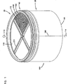
In Verbindung mit dem Filterpaket 50 ist eine Vielfalt von Gehäusen verwendbar. Bei der in 8 dargestellten speziellen Ausführungsform besitzt das Gehäuse 305 einen Körper oder ein erstes Gehäuseteil 310 und einen lösbaren Deckel oder zweites Gehäuseteil 315. Bei einigen Ausführungsformen ist das erste Gehäuseteil 310 an einem Objekt, z. B. einem Lastkraftwagen, befestigt. Das zweite Gehäuseteil 315 ist mittels einer Verriegelung 320 lösbar an dem ersten Gehäuseteil 310 befestigt. Vorzugsweise besitzt die Verriegelung 320 mehrere Riegel 325.In conjunction with the filter pack 50 a variety of housings are usable. At the in 8th illustrated special embodiment has the housing 305 a body or a first housing part 310 and a detachable lid or second housing part 315 , In some embodiments, the first housing part 310 on an object, e.g. As a truck attached. The second housing part 315 is by means of a lock 320 detachable on the first housing part 310 attached. Preferably, the lock has 320 several bars 325 ,

Obwohl das Gehäuse die verschiedensten Querschnittskonfigurationen haben kann, haben bei der dargestellten speziellen Ausführungsform das erste und das zweite Gehäuseteil 310, 315 kreisförmigen Querschnitt. Bei der dargestellten Ausführungsform besitzt das erste Gehäuseteil 310 einen Austrittsbereich 330. Die Konstruktion des Austrittsbereiches 330 gestattet es dem Fluid während des Betriebes aus dem Luftfilter 300 auszutreten. In gleicher Weise besitzt das zweite Gehäuseteil einen Eintrittsbereich 335. Die Konstruktion des Eintrittsbereiches 335 gestattet es dem Fluid während des Betriebes in den Luftfilter 300 einzutreten. Bei bevorzugten Konstruktionen ist das Gehäuse 305 ein „in-line” Gehäuse. D. h., der Austrittsbereich 330 und der Eintrittsbereich 335 fluchten koaxial miteinander, wodurch der Luftstrom in der gleichen Richtung durch den Eintrittsbereich 335 und den Austrittsbereich 330 strömen kann. Dies ist aus 9 ersichtlich.Although the housing may have a variety of cross-sectional configurations, in the particular embodiment illustrated, the first and second housing portions 310 . 315 circular cross-section. In the illustrated embodiment, the first housing part 310 an exit area 330 , The construction of the exit area 330 allows the fluid from the air filter during operation 300 withdraw. In the same way, the second housing part has an inlet area 335 , The construction of the entrance area 335 allows the fluid during operation in the air filter 300 enter. In preferred constructions, the housing is 305 an "in-line" housing. That is, the exit area 330 and the entry area 335 coaxial with each other, causing the air flow in the same direction through the inlet area 335 and the exit area 330 can flow. This is off 9 seen.

Das Filterpaket 50 ist vorzugsweise so konstruiert und arrangiert, dass es mit der Seitenwand 260 des Gehäuses 305 eine Presspassung bilden kann. In der in 9 dargestellten Ausführungsform ist das zweite Ende 110 des Filterpaketes mit dem Rahmen 205 und dem kompressiblen Dichtungselement 250 in das erste Gehäuseteil 310 eingesetzt. Das Filterpaket 50 ist in einer Presspassung derart in das erste Gehäuseteil 310 eingesetzt, dass das kompressible Dichtungselement 250 zwischen dem Dichtungsträger 263 des Rahmens 205 und der Seitenwand 260 des ersten Gehäuseteiles 310 zusammengepresst wird, um zwischen diesen eine radiale Dichtung 172 zu bilden.The filter package 50 is preferably constructed and arranged to fit with the side wall 260 of the housing 305 can form a press fit. In the in 9 illustrated embodiment is the second end 110 of the filter package with the frame 205 and the compressible sealing element 250 in the first housing part 310 used. The filter package 50 is in a press fit in the first housing part 310 used that compressible sealing element 250 between the seal carrier 263 of the frame 205 and the side wall 260 of the first housing part 310 is compressed to form a radial seal between them 172 to build.

Während des Betriebes der in 9 dargestellten Ausführungsform tritt das Fluid in der Richtung 306 in den Eintrittsbereich 335 des zweiten Gehäuseteiles 315 des Gehäuses 300 ein. Des Fluid durchströmt die Filterkonstruktion 100. Während das Fluid die Filterkonstruktion 100 durchströmt, werden Verunreinigungen aus dem Fluid entfernt. Das Fluid verlässt das Gehäuse 300 im Austrittsbereich 330 in der Richtung 307. Des komprimierbare Dichtungselement 250 des Dichtungssystems 60 bildet eine radiale Dichtung 172, um zu verhindern, dass verunreinigtes Fluid aus dem Gehäuse 300 austritt ohne die Filterkonstruktion 100 durchflossen zu haben.During operation of the in 9 In the illustrated embodiment, the fluid enters in the direction 306 in the entrance area 335 of the second housing part 315 of the housing 300 one. The fluid flows through the filter construction 100 , While the fluid is the filter construction 100 flows through, impurities are removed from the fluid. The fluid leaves the housing 300 in the exit area 330 in that direction 307 , The compressible sealing element 250 of the sealing system 60 forms a radial seal 172 To prevent contaminated fluid from the housing 300 exit without the filter construction 100 to have flowed through.

C. Fig. 17 + Fig. 18 C. Fig. 17 + Fig. 18

Es ist offensichtlich, dass das Filterpaket 50 zusätzliche Separatoren haben kann, um sicherzustellen, dass ein angemessener Grad der Filterung erreicht wird. Die Separatoren können entweder stromaufwärts von dem Filterpaket 50 oder stromabwärts von dem Filterpaket 50 angeordnet sein; abhängig von der speziellen Anwendung und der gewünschten Ergebnisse. Diese Separatoren können in einigen Ausführungsformen in Form von Vorreinigern oder Nachreinigern (z. B. Sicherheitsfiltern oder Sekundärfiltern) eingesetzt werden. Ferner können diese Separatoren in Form von Einschicht oder Mehrschicht Filtermedien eingesetzt werden und entweder stromaufwärts oder stromabwärts von der Filterkonstruktion 100 angeordnet werden. Die in diesen Anwendungen eingesetzten Filtermedia werden üblicherweise aufgrund des gewünschten Filtergrades und der durch das Filtermedium bedingten Strömungswiderstände ausgewählt. Z. B., kann es bei gewissen Anwendungsformen vorkommen, dass es wünschenswert ist, grosse Partikel (d. h. grosse Müllstücke wie z. B. Blätter, Schmetterlinge, Schmutzklumpen o. dgl.) herauszufiltern, ohne weitere zusätzliche Strömungswiderstände hinzuzufügen. In diesen Anwendungsformen kann eine Mediumschicht, wie z. B. ein Sieb oder ein Rechen stromaufwärts von der Filterkonstruktion angeordnet werden. Es kann auch wünschenswert sein, unmittelbar stromabwärts von der Filterkonstruktion 100 eine zusätzliche Filterung vorzusehen. Dies kann durch eine Schicht (oder mehrere Schichten eines Filtermediums unmittelbar stromabwärts von der Filterkonstruktion 100 erreicht werden.It is obvious that the filter package 50 may have additional separators to ensure that an adequate level of filtering is achieved. The separators may either be upstream of the filter pack 50 or downstream of the filter pack 50 be arranged; depending on the specific application and the desired results. These separators may be used in some embodiments in the form of pre-cleaners or post-cleaners (eg, safety filters or secondary filters). Further, these separators may be employed in the form of single layer or multi-layer filter media and either upstream or downstream of the filter construction 100 to be ordered. The filter media used in these applications are usually selected on the basis of the desired degree of filtering and the flow resistance caused by the filter medium. For example, in some applications, it may be desirable to filter out large particles (ie, large pieces of debris such as leaves, butterflies, clods, or the like) without adding additional flow resistance. In these applications, a medium layer, such as. As a sieve or a rake upstream of the filter construction can be arranged. It may also be desirable immediately downstream of the filter construction 100 to provide additional filtering. This may be through a layer (or multiple layers of a filter medium immediately downstream of the filter construction 100 be achieved.

17 zeigt eine alternative Ausführungsform des Filterpaketes 50 gekennzeichnet durch die Bezugszahl 50'. Das Filterpaket 50' ist analog zum Filterpaket 50 gemäss 1 konfiguriert und konstruiert, mit der Ausnahme, der ersten Strömungsfläche 105', die einer stromaufwärts angeordneten oder Eintrittsfläche 106' entspricht. 17 zeigt eine Vorderansicht des Filterpaketes 50' mit Sicht auf das stromaufwärtige Ende 106'; bei dem in 17 dargestellten speziellen Filterpaket 50' ist die gesamte Strom aufwärts gelegene Fläche 106' mit einer Schicht eines Filtermediums 107' abgedeckt, um grosse Partikel aus dem Gasstrom zu separieren, bevor der Gasstrom in die Filterkonstruktion 100 eintritt. Abhängig von der Anwendung und dem gewünschten Grad der Filtration und dem Strömungswiderstand können die verschiedensten Arten für das Medium 107' verwendet werden. In vielen typischen Anwendungen ist das Filtermedium 107' so bemessen, dass es die Separation von Partikeln, wie z. B. Schmetterlingen, Blättern, grossen Schmutz-klumpen und anderen Abfallarten erlaubt. Eine Filtermediumart, die für diese Zwecke einsetzbar ist, besitzt die folgenden Charakteristiken und Eigenschaften: Polyestermaterial; 50 Gew.-% der Fasern mit ungefähr 15 Dernier und 50 Gew.-% der Fasern mit ungefähr 6 Dernier; der die Fasern zusammenhaltende Binder ist ein ölbeständiger gummimodifizierter PVC; ein Basisgewicht von 224 g/m2 (6,6 oz/yd2); eine Dicke von ungefähr 9,4 mm (0,37 inch) eine Durchlässigkeit von ungefähr 1068 m/min (3500 ft/m) mit einem 6,25 mm (0,5 inch) H2O Strömungswiderstand. 17 shows an alternative embodiment of the filter pack 50 characterized by the reference number 50 ' , The filter package 50 ' is analogous to the filter package 50 according to 1 configured and constructed, with the exception of the first flow area 105 ' that is an upstream or entrance surface 106 ' equivalent. 17 shows a front view of the filter pack 50 ' with a view of the upstream end 106 '; at the in 17 illustrated special filter package 50 ' is the total electricity upstream area 106 ' with a layer of a filter medium 107 ' covered to separate large particles from the gas stream, before the gas flow into the filter construction 100 entry. Depending on the application and the desired degree of filtration and flow resistance can be of various types for the medium 107 ' be used. In many typical applications, the filter medium is 107 ' so that it separates the separation of particles, such. As butterflies, leaves, large debris and other types of waste allowed. A type of filter medium that can be used for these purposes has the following characteristics and properties: polyester material; 50% by weight of the approximately 15 denier fibers and 50% by weight of the approximately 6 denier fibers; the fiber-bonding binder is an oil-resistant rubber-modified PVC; a basis weight of 224 g / m 2 (6.6 oz / yd 2 ); a thickness of about 9.7 mm (0.37 inches) a transmittance of about 1068 m / min (3500 ft / m) with a 6.25 mm (0.5 inch) H 2 O flow resistance.

Wie oben erwähnt, kann es auch wünschenswert sein, stromabwärts von der Filterkonstruktion 100 eine Separation vorzusehen. Ein Beispiel ist in 18 dargestellt. 18 zeigt eine Frontansicht einer alternativen Ausführungsform des Filterpaketes 55 von der zweiten Strömungsfläche 110'' her. Das in 18 dargestellte Filterpaket 50'' ist analog zu dem Filterpaket 50 gemäss 1 konstruiert, jedoch mit der Ausnahme, dass ein zusätzlicher Separator 111'' stromabwärts von der Filterkonstruktion 100 angeordnet ist. Obwohl eine Vielzahl von Ausführungsformen betrachtet wird, ist bei der speziellen Ausführungsform gemäss 18 der Separator 111'' in Form einer Mediumschicht 112'' stromabwärts von der Filterkonstruktion 110 angeordnet. Die Filtermediumschicht 112'' kann entweder unmittelbar benachbart und an der Filterkonstruktion 100 angeordnet sein, oder sie kann stromabwärts von dem Rahmen 205'' angeordnet sein. In der in 18 dargestellten Ausführungsform ist die Filtermediumschicht 112'' unmittelbar stromabwärts an der Filterkonstruktion 100 angeordnet. D. h., die Filtermediumschicht 112'' ist zwischen der Filterkonstruktion 100 und den Kreuzstreben 210'' des Rahmens 205'' angeordnet.As mentioned above, it may also be desirable downstream of the filter construction 100 to provide a separation. An example is in 18 shown. 18 shows a front view of an alternative embodiment of the filter pack 55 from the second flow area 110 '' ago. This in 18 illustrated filter package 50 '' is analogous to the filter package 50 according to 1 designed, but with the exception that an additional separator 111 '' downstream of the filter construction 100 is arranged. Although a variety of embodiments are contemplated, according to the particular embodiment 18 the separator 111 '' in the form of a medium layer 112 '' downstream of the filter construction 110 arranged. The filter media layer 112 '' can either be immediately adjacent and to the filter construction 100 be arranged, or it may be downstream of the frame 205 '' be arranged. In the in 18 The embodiment shown is the filter medium layer 112 '' immediately downstream of the filter construction 100 arranged. That is, the filter medium layer 112 '' is between the filter construction 100 and the cross struts 210 '' of the frame 205 '' arranged.

Die Art der verwendeten Filtermediumschicht 112'' hängt von dem gewünschten Filterwirkungsgrad und dem Betrag des eingebrachten Strömungswiderstandes ab. Das Filtermedium 112'' kann aus einer einzigen Schicht oder mehreren Schichten bestehen. In der in 18 dargestellten Ausführungsform besteht das Medium 112'' aus einem nicht gewebten, nicht gefalteten faserigen Tiefenmedium (depth media) 113''. Ein für Tiefenmedia (depth media) 113'' verwendbares Material besitzt folgende Eigenschaften:

  • – 1 Schicht 136163 g/m2 (4,0–4,8 oz/yd2) Polyester-Fasern Tiefenmedium (depth media) (gemischte Fasern);
  • – 14–18 mm (0,55–0,70 inch) Dicke im freien Zustand (gemessen bei unter 1,4 mbar (0,002 psi) Kompression);
  • – durchschnittlicher Faserdurchmesser ungefähr 21,0 μm (Mengen gewichteter Durchschnitt) oder 16,3 μm (Längen gewichteter Durchschnitt);
  • – Durchlässigkeit (minimum) 152 m/min (500 ft/min);
  • – ungebundene Feststoffe ungefähr 0,6 bis 1,0%, üblicherweise ungefähr 0,7%.
The type of filter media layer used 112 '' depends on the desired filter efficiency and the amount of introduced flow resistance. The filter medium 112 '' can consist of a single layer or multiple layers. In the in 18 illustrated embodiment, the medium 112 '' a non-woven, unfolded, fibrous depth media (depth media) 113 '' , One for depth media (depth media) 113 '' usable material has the following properties:
  • - 1 shift 136 - 163 g / m 2 (4.0-4.8 oz / yd 2 ) polyester fibers depth media (mixed fibers);
  • 0.55-0.70 inch thickness in free state (measured at below 1.4 mbar (0.002 psi) compression);
  • Average fiber diameter about 21.0 μm (weighted average) or 16.3 μm (weighted average);
  • Permeability (minimum) 152 m / min (500 ft / min);
  • Unbound solids about 0.6 to 1.0%, usually about 0.7%.

Es ist beabsichtigt, dass es bei verschiedenen Ausführungsformen wünschenswert ist, ein Filterpaket 50 mit einem Vorfilter 107' und einem Nachfilter 111'' vorzusehen. It is contemplated that in various embodiments, it is desirable to have a filter pack 50 with a pre-filter 107 ' and a postfilter 111 '' provided.

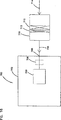
D. Fig. 10–Fig. 15D. Fig. 10-Fig. 15

Die Aufmerksamkeit wird auf 10 gerichtet. 10 zeigt eine perspektivische Ansicht einer weiteren Ausführungsform eines Filterpaketes 450. In der dargestellten Ausführungsform besitzt das Filterpaket 450 ein Filtermedium 455 und ein Dichtungssystem 460. Das Filtermedium 455 ist ausgelegt, um Verunreinigungen aus einem Fluid, z. B. Luft zu entfernen, das das Filtermedium 455 durchströmt. Das Dichtungssystem 460 ist ausgelegt, um das Filtermedium 455 gegen ein Gehäuse oder einen Kanal abzudichten.The attention is on 10 directed. 10 shows a perspective view of another embodiment of a filter pack 450 , In the illustrated embodiment, the filter pack has 450 a filter medium 455 and a sealing system 460 , The filter medium 455 is designed to remove contaminants from a fluid, e.g. B. to remove air, which is the filter medium 455 flows through. The sealing system 460 is designed to filter the media 455 To seal against a housing or a channel.

In speziellen bevorzugten Ausführungsformen ist das Filtermedium 455 in einer Filterkonstruktion 470 konfiguriert, die eine erste Strömungsfläche 471 und eine gegenüberliegende zweite Strömungsfläche 472 besitzt. In der in 11 dargestellten speziellen Ausführungsform ist die Filterkonstruktion 470 für Durchgangsströmung konfiguriert. D. h., wie oben beschrieben, dass das zu filternde Fluid in die erste Strömungsfläche 471 in einer Richtung 477 (10) eintritt, und die zweite Strömungsfläche 472 in der gleichen Richtung 478 (10) verlässt.In specific preferred embodiments, the filter medium is 455 in a filter construction 470 configured having a first flow area 471 and an opposite second flow surface 472 has. In the in 11 shown special embodiment is the filter construction 470 configured for throughflow. That is, as described above, the fluid to be filtered into the first flow surface 471 in one direction 477 ( 10 ), and the second flow surface 472 in the same direction 478 ( 10 ) leaves.

Die Filterkonstruktion 470 kann zahlreiche Konfigurationen und Querschnitt-formen haben. In der speziellen Ausführungsform gemäss 11 besitzt die Filterkonstruktion 470 einen nicht kreisförmigen Querschnitt. Insbesondere besitzt die in 11 dargestellte Ausführungsform der Filterkonstruktion 470 einen unrunden oder „rennbahn-förmigen” Querschnitt. Mit dem Begriff „rennbahn-förmiger” Querschnitt ist gemeint, dass die Filterkonstruktion 470 ein erstes halbkreisförmiges Ende 511 und ein zweites halbkreisförmiges Ende 512 besitzt, die durch ein Paar gerader Segmente 513, 514 miteinander verbunden sind.The filter construction 470 can have numerous configurations and cross-sectional shapes. In the specific embodiment according to 11 owns the filter construction 470 a non-circular cross-section. In particular, the in 11 illustrated embodiment of the filter construction 470 a non-circular or "racetrack-shaped" cross-section. By the term "racetrack-shaped" cross-section is meant that the filter construction 470 a first semicircular end 511 and a second semicircular end 512 owns that through a pair of straight segments 513 . 514 connected to each other.

Im allgemeinen ist die Filterkonstruktion 470 eine gewickelte Konstruktion. D. h., die Filterkonstruktion 470 besteht aus einer Schicht eines Filtermediums, das vollständig und wiederholt um ein Zentrum gewickelt ist. Bei speziellen bevorzugten Ausführungsformen ist die gewickelte Konstruktion eine Spule, bei der eine Schicht eines Filtermediums mehrmals um ein Zentrum gewickelt ist. In weiteren bevorzugten Ausführungsformen ist die Filterkonstruktion 470 eine gerollte Konstruktion, üblicherweise eine Rolle aus Filtermedium, z. B. durchlässigem gefalteten Filtermedium.In general, the filter construction is 470 a wound construction. That is, the filter construction 470 consists of a layer of a filter medium that is completely and repeatedly wrapped around a center. In specific preferred embodiments, the wound construction is a spool in which a layer of filter media is wrapped several times around a center. In other preferred embodiments, the filter construction is 470 a rolled construction, usually a roll of filter medium, e.g. B. permeable folded filter medium.

Es können viele verschiedene Arten zur Herstellung der Filtermediumkonstruktion 470 verwendet werden. Bei einigen Techniken wird ein einseitiges Filtermedium, wie z. B. das Filtermedium 122 gemäss 2 um eine zentrale Spindel oder eine andere Struktur, die ein Tragelement für die Wicklung darstellt, gewickelt. Die zentrale Spindel kann entfernt werden, oder belassen werden, um das Zentrum der Filterkonstruktion 470 einzurasten. Bei der speziellen Ausführungsform gemäss 11 ist ein zentraler Kern 454 dargestellt, der das Zentrum des Filtermediums 455 bildet.There are many different ways to make the filter media design 470 be used. In some techniques, a one-sided filter medium, such as. B. the filter medium 122 according to 2 around a central spindle or other structure which is a supporting element for the winding wound. The central spindle can be removed, or left to the center of the filter construction 470 lock. In the specific embodiment according to 11 is a central core 454 represented, which is the center of the filter medium 455 forms.

In 10 und 11 sind bestimmte Teile 475 dargestellt, die die Falten einschliesslich der offenen und der geschlossenen Ende zeigen. Es ist offensichtlich, dass dieser Teil oder dieser Abschnitt 475 die gesamte Strömungsfläche 472 repräsentiert (sowie auch die erste Strömungsfläche 471). Zum Zwecke der Klarheit und der Vereinfachung sind die Falten nicht in den restlichen Teilen der Strömungsfläche 472 dargestellt. Draufsichten und Unteransichten und auch Seitenansichten des Filterpaketes 450, das in den hier beschriebenen Systemen und Vorrichtungen einsetzbar ist, sind in der gemeinsam eingereichten und gemeinsam zugeordneten US Patent Anmeldung Serien Nr. 29/101.139, eingereicht am 26.02, 1999 unter dem Titel „Filter element having sealing system” beschrieben, die hiermit eingeschlossen wird.In 10 and 11 are certain parts 475 shown showing the folds including the open and closed ends. It is obvious that this part or this section 475 the entire flow area 472 represents (as well as the first flow area 471 ). For the sake of clarity and simplicity, the wrinkles are not in the remaining parts of the flow area 472 shown. Top views and bottom views and side views of the filter pack 450 Applicable in the systems and devices described herein are described in commonly assigned and commonly assigned US Patent Application Serial No. 29 / 101,139, filed on 26/02/99, entitled "Filter Element Having Sealing System", which is hereby incorporated by reference becomes.

Wie bei der Ausführungsform gemäss 1 besitzt das Filterpaket 450 ein Dichtungssystem 460. Bei bevorzugten Ausführungsformen besitzt das Dichtungssystem 460 einen Rahmen 605 und ein Dichtungselement 650.As in the embodiment according to 1 owns the filter package 450 a sealing system 460 , In preferred embodiments, the sealing system has 460 a frame 605 and a sealing element 650 ,

Obwohl zahlreiche verschiedene Ausführungsformen hiermit beabsichtigt sind, ist eine spezielle Ausführungsform des Rahmens 605 in einer perspektivischen Ansicht in 12 dargestellt.Although numerous different embodiments are hereby intended, one particular embodiment of the frame is 605 in a perspective view in 12 shown.

In der in 12 dargestellten speziellen Ausführungsform hat der Rahmen 605 eine nicht-kreisförmige Form, z. B. eine unrunde und insbesondere eine „Rennbahn” Form; er ist so angeordnet und konfiguriert, dass er an das zweite Ende 510 des Filtermediums 455 anbringbar ist. Insbesondere besitzt der Rahmen 605 einen Bund oder eine Schürze oder eine abwärts ragende Lippe 651, die im allgemeinen „rennbahn-förmig” geformt ist. Die Lippe 651 erstreckt sich abwärts von einer Unterfläche 652 der Querstreben 610. Die Lippe 651 ist so angeordnet und konfiguriert, dass sie sich radial um das zweite Ende 570 der Filterkonstruktion 470 erstreckt. Bei der in 10 dargestellten Ausführungsform erstreckt sich die Lippe 651 des Rahmen 605 radial um die zweite Endfläche der Filterkonstruktion 470 derart, dass sich die Lippe 651 von der Unterfläche 652 der Querstreben 610 des zweiten Endes 510 der Filterkonstruktion 470 einwärts erstreckt, wodurch ein Überlappungsbereich 555 (15) gebildet wird.In the in 12 illustrated special embodiment, the frame 605 a non-circular shape, e.g. B. a non-circular and especially a "racetrack"shape; he is so arranged and configured that he is at the second end 510 of the filter medium 455 attachable. In particular, the frame has 605 a waistband or an apron or a downturned lip 651 , which is generally shaped "racetrack-shaped". The lip 651 extends downwards from a lower surface 652 the cross struts 610 , The lip 651 is arranged and configured so that it extends radially around the second end 570 the filter construction 470 extends. At the in 10 illustrated embodiment, the lip extends 651 of the frame 605 radially around the second end surface of the filter construction 470 such that the lip 651 from the lower surface 652 the cross struts 610 the second end 510 the filter construction 470 extends inwardly, creating an overlap area 555 ( 15 ) is formed.

Der Rahmen 605 kann auf die veschiedensten Arten an der Filterkonstruktion 470 befestigt werden. Eine spezielle bequeme Art ist, den Rahmen 605 mit einem Kleber an der Filterkonstruktion 470 zu befestigen. In der dargestellten spezifischen Ausführungsform (15) ist der Kleber in dem vorher beschriebenen Überlappungsbereich 555 zwischen dem Rahmen 605 und der Filterkonstruktion 470 plaziert. The frame 605 can filter in the most different ways on the filter construction 470 be attached. A special comfortable style is the frame 605 with an adhesive on the filter construction 470 to fix. In the illustrated specific embodiment ( 15 ), the adhesive is in the previously described overlap area 555 between the frame 605 and the filter construction 470 placed.

Während des Betriebes der dargestellten Ausführungsformen werden auf den Umfang des Rahmens 605 nach innen gerichtete Kräfte ausgeübt. Die auf die halbkreisförmigen Enden 511, 512 nach innen wirkenden Kräfte können bewirken, dass sich die geraden Segmente 513, 514 biegen oder knicken. Eine strukturelle Eigenschaft des Rahmen 605 ist, das Knicken der geraden Segmente 513, 514 zu verhindern. Obwohl hierbei eine Vielfalt von Strukturen in Betracht zu ziehen ist, sind in der in 12 dargestellten speziellen Ausführungsform Kreuzstreben 610 vorgesehen, um die strukturelle Steife und die Stützung der geraden Segmente 513, 514 zu gewährleisten. Gemäss 12 bilden die speziellen Querstreben 610 zwischen den einander gegenüberliegenden geraden Segmenten 513, 514 ein Gitterwerk 612. Das Gitterwerk 612 besitzt mehrere steife Streben 614, die vorzugsweise als ein Teil mit dem restlichen Teil des Rahmens 605 geformt sind.During operation of the illustrated embodiments, the scope of the frame 605 Inwardly directed forces exercised. The on the semi-circular ends 511 . 512 inward forces can cause the straight segments 513 . 514 bend or bend. A structural property of the frame 605 is the kinking of the straight segments 513 . 514 to prevent. Although a variety of structures are to be considered here, in the 12 illustrated special embodiment cross struts 610 provided to the structural stiffness and the support of the straight segments 513 . 514 to ensure. According to 12 make the special cross struts 610 between the opposing straight segments 513 . 514 a latticework 612 , The gridwork 612 has several stiff struts 614 preferably as part of the rest of the frame 605 are shaped.

Bei gewissen bevorzugten Ausführungsformen ist der Rahmen 605 analog zum Rahmen 205 konstruiert. Demgemäss besitzt der Rahmen 605 gemäss 12 und 13 Spitzenteile 663. Bei bevorzugten Ausführungsformen dienen die Spitzenteile 663 als ringförmige Dichtungsträger. Bei der dargestellten Ausführungsform hat das Spitzenteil 663 die gleiche Querschnittkonfiguration wie die Filterkonstruktion 470. In der speziellen Ausführungsform gemäss 12 ist das Spitzenteil nicht kreisförmig sondern „rennbahn-förmig”. Bei bevorzugten Ausführungsformen mit Bezug auf die spezielle Ausführungsform gemäss 13 besitzt der Rahmen 605 zwischen den Spitzenteilen 663 und der abwärts ragenden Lippe 651 einen Bund 653. Der Bund 653 bildet einen Übergangsbereich zwischen der Querschnittsbreite der Lippe 651 und der schmaleren Querschnittsbreite des Spitzenteiles 663.In certain preferred embodiments, the frame is 605 analogous to the frame 205 constructed. Accordingly, the frame has 605 according to 12 and 13 pointed parts 663 , In preferred embodiments, the tip portions serve 663 as an annular seal carrier. In the illustrated embodiment, the tip portion 663 the same cross-sectional configuration as the filter construction 470 , In the specific embodiment according to 12 the top part is not circular but "raceway-shaped". In preferred embodiments with reference to the specific embodiment according to 13 owns the frame 605 between the top parts 663 and the lip sticking down 651 a covenant 653 , The Bund 653 forms a transition region between the cross-sectional width of the lip 651 and the narrower cross-sectional width of the tip part 663 ,

Bei bevorzugten Systemen besitzt das kompressible Dichtungselement 650 eine Struktur, die analog ist zu der Struktur des kompressiblen Dichtungselementes 250 gemäss 7.In preferred systems, the compressible sealing element has 650 a structure analogous to the structure of the compressible sealing element 250 according to 7 ,

Vorzugsweise wird das Filterpaket 450 in einen Kanal oder in ein Luftfilter-gehäuse eingesetzt. Bei speziellen bevorzugten Anwendungsformen ist das Luftfiltergehäuse ein „in-line” Gehäuse. 14 zeigt einen Luftfilter 670 mit einem „in-line” Gehäuse. Das in 14 dargestellte Gehäuse besteht aus zwei Gehäuseteilen, einem Deckel 674 und einem Behälterteil 676. Der Deckel 674 bildet einen Lufteintritt 678. Der Behälterteil 676 bildet einen Luftaustritt 680. Das Gehäuse 672 beinhaltet ferner stromaufwärts von dem Filterpaket 450 ein Vorreinigungselement 679, ein solches Vorreinigungselement ist in US Patent Nr. 2.887.177 und 4.162.906 beschrieben und hiermit eingeschlossen. In der dargestellten Ausführungsform ist das Vorreinigungselement 679 in dem Deckel 674 angeordnet. Der Deckel 674 besitzt einen Staubauswurf 681, der in dem Vorreinigungselement 679 angesammelten Staub und andere Verunreinigungen auswirft.Preferably, the filter pack 450 used in a duct or in an air filter housing. In special preferred embodiments, the air cleaner housing is an "in-line" housing. 14 shows an air filter 670 with an "in-line" housing. This in 14 shown housing consists of two housing parts, a lid 674 and a container part 676 , The lid 674 forms an air inlet 678 , The container part 676 forms an air outlet 680 , The housing 672 further includes upstream of the filter pack 450 a pre-cleaning element 679 , such a pre-cleaning element is in U.S. Patent No. 2,887,177 and 4162906 described and included. In the illustrated embodiment, the pre-cleaning element 679 in the lid 674 arranged. The lid 674 has a dust ejection 681 which is in the pre-cleaning element 679 accumulates accumulated dust and other impurities.

15 ist ein schematischer Querschnitt des Luftfilters 670 gemäss 14, in dem das eingebaute Filterpaket 450 dargestellt ist. 15 is a schematic cross section of the air filter 670 according to 14 in which the built-in filter package 450 is shown.

Das kompressible Dichtungselement 650 ist zwischen der Seitenwand 660 und dem Spitzenteil 663 des Rahmens 605 zusammengepresst. Durch den Press-sitz des Filterpaketes 450 ist das kompressible Dichtungselement 650 zwischen dem Rahmen 605 (speziell in der besonderen dargestellten Ausführungsform des Spitzenteiles 663) und der Seitenwand 660 zusammengepresst. Nach der Zusammenpressung übt das kompressible Dichtungselement 650 eine Kraft auf die Seitenwand 660 aus, da das kompressible Dichtungselement 650 versucht sich nach aussen in seinen Ausgangszustand auszudehnen; dadurch wird eine radiale Dichtung 685 mit der Seitenwand 660 gebildet.The compressible sealing element 650 is between the sidewall 660 and the top part 663 of the frame 605 compressed. Due to the press fit of the filter pack 450 is the compressible sealing element 650 between the frame 605 (Especially in the particular illustrated embodiment of the tip part 663 ) and the side wall 660 compressed. After compression, the compressible sealing element exerts 650 a force on the sidewall 660 because of the compressible sealing element 650 tries to expand outward to its initial state; This will create a radial seal 685 with the sidewall 660 educated.

E. Systeme und BetriebsverfahrenE. Systems and Operating Procedures

Die hier beschriebenen Filterkonstruktionen und Vorrichtungen sind in den verschiedensten Systemen einsetzbar. Eine spezielle Systemart 700 ist in 16 schematisch dargestellt. 16 zeigt schematisch ein Gerät 207, z. B. am Fahrzeug mit deinem Motor 703 mit einem definierten Zuluftbedarf, z. B. mindestens 500 cfm und typischerweise 700–1200 cfm. Das Gerät 702 kann ein Bus, ein Lastkraftwagen, ein Geländewagen, ein Traktor, ein Wasserfahr-zeug, z. B. ein Motorboot o. dgl. Sein. Der Motor 703 treibt das Gerät 702 unter Verwendung eines Luft-Brennstoff-Gemisches an. Gemäss 16 wird der Luftstrom im Eintrittsbereich 705 von dem Motor angesaugt. Ein optionaler Turbolader 706, in gestrichelten Linien dargestellt, kann die Ansaugluft des Motors 703 aufladen. Ein Luftfilter 710 mit einer Filterkonstruktion 712 und einem Sekundärelement 713 ist stromaufwärts von dem Motor 703 und dem Turbolader 706 angeordnet. Im allgemeinen wird im Betrieb Luft in Richtung des Pfeiles 714 in den Luftfilter 710, durch ein Primärelement 712 und durch das Sekundärelement 713 angesaugt. Dort werden Feststoffpartikel und Verunreinigungen aus der Luft entfernt. Die gereinigte Luft strömt stromabwärts in Richtung des Pfeiles 716 in den Eintrittsbereich 705. Von dort strömt die Luft in den Motor 703, um das Gerät 702 anzutreiben.The filter designs and devices described herein can be used in a variety of systems. A special system type 700 is in 16 shown schematically. 16 schematically shows a device 207 , z. B. on the vehicle with your engine 703 with a defined fresh air requirement, eg. At least 500 cfm and typically 700-1200 cfm. The device 702 may be a bus, a truck, an off-road vehicle, a tractor, a watercraft, z. B. a motor boat o. The like. Be. The motor 703 drives the device 702 using an air-fuel mixture. According to 16 the airflow is in the inlet area 705 sucked by the engine. An optional turbocharger 706 , shown in dashed lines, the intake air of the engine 703 charge. An air filter 710 with a filter construction 712 and a secondary element 713 is upstream of the engine 703 and the turbocharger 706 arranged. In general, in operation, air will move in the direction of the arrow 714 in the air filter 710 , by a primary element 712 and by the secondary element 713 sucked. There, solid particles and impurities are removed from the air. The cleaned air flows downstream in the direction of the arrow 716 in the entrance area 705 , From There the air flows into the engine 703 to the device 702 drive.

F. Austausch und ErsatzF. Replacement and replacement

Bei bestimmten bevorzugten Anwendungsarten sind die hier beschriebenen Filterpakete entfernbar und austauschbar, in welchem System auch immer sie installiert sind. Z. B. kann das Filterpaket 50 bzw. das Filterpaket 650 in ein Luftfiltergehäuse gemäss 9 bzw. 15 eingesetzt werden. Nach einer bestimmten Betriebsstundenzahl ist das Filtermedium in der Filterkonstruktion verstopft und der Strömungswiderstand des Filterpaketes steigt an. Bei bevorzugten Anwendungsarten werden die Filterpakete periodisch ausgetauscht, um eine wirksame Entfernung der Feststoffpartikel aus dem Fluid ohne einen zu hohen Strömungswiderstand zu gewährleisten.In certain preferred applications, the filter packs described herein are removable and replaceable, in whatever system they are installed. For example, the filter package 50 or the filter package 650 in an air filter housing according to 9 respectively. 15 be used. After a certain number of operating hours, the filter medium in the filter construction is clogged and the flow resistance of the filter pack increases. In preferred applications, the filter packs are periodically changed to ensure effective removal of the solid particles from the fluid without too high a flow resistance.

In einigen Anwendungsarten besitzen die hier beschriebenen Filterkonstruktionen eine visuelle Anzeige der Standzeit. Einige Systeme besitzen eine Strömungswiderstandsanzeige, um dem Anwender Informationen über den geeigneten Austauschzeitpunkt des Filterpaketes zu liefern.In some applications, the filter designs described herein have a visual indication of tool life. Some systems have a flow resistance indicator to provide the user with information about the appropriate replacement timing of the filter pack.

Um die hier beschriebenen Luftfilterkonstruktionen zu warten muss der Benutzer Zugang zu dem Filterpaket haben. Wenn z. B. das Luftfilterpaket in einem Luftfiltergehäuse, wie z. B. in 9 oder 15 dargestellt, eingesetzt ist, wird der Benutzer den Deckel von dem Gehäuselement entriegeln und den Deckel von dem Gehäuseelement entfernen. Dadurch wird eine Öffnung freigegeben. Der Benutzer ergreift das Filterpaket und löst die radiale Dichtung, die zwischen dem Filterpaket und der Seitenwand des Gehäuses oder des Kanals besteht. Bei speziellen Systemen sind das Dichtungselement und das Gehäuse oder der Kanal so konstruiert, dass der Anwender eine Kraft von nicht mehr als ungefähr 36 kg (80 lbs), vorzugsweise nicht mehr als 22,7 kg (50 lbs) und bei einigen Anwendungsarten zwischen 6,8 und 18 kg (zwischen 15 und 40 lbs) aufbringen muss, um die radiale Dichtung zu lösen und das Filterpaket zu entfernen. Der Anwender zieht dann das Filterpaket durch die von dem Gehäusekörper gebildete Öffnung. Das alte Filterpaket kann dann entsorgt werden. Bei speziellem bevorzugten Systemen besteht das Filterpaket aus nicht-metallischen Materialien, so dass es leicht verbrennbar ist. In einigen bevorzugten Konstruktionen enthält das Filterpaket z. B. mindestens 95% und typischerweise mindestens 98% nicht-metallische Materialien.To service the air filter designs described herein, the user must have access to the filter pack. If z. B. the air filter pack in an air filter housing, such. In 9 or 15 shown, the user will unlock the lid of the housing member and remove the lid from the housing member. As a result, an opening is released. The user grasps the filter pack and releases the radial seal that exists between the filter pack and the sidewall of the housing or channel. In specific systems, the seal member and housing or channel are designed so that the user has a force of no more than about 80 lbs, preferably no more than 50 lbs, and in some applications, between six and six , 8 and 18 kg (between 15 and 40 lbs) must be applied to loosen the radial seal and remove the filter pack. The user then pulls the filter pack through the opening formed by the housing body. The old filter package can then be disposed of. In particular preferred systems, the filter pack is made of non-metallic materials so that it is easily combustible. In some preferred constructions, the filter pack contains e.g. At least 95% and typically at least 98% non-metallic materials.

Zur Installation eines neuen Filterpaketes ergreift der Anwender das Filterpaket und führt es durch eine Öffnung des Kanals oder des Gehäuses ein. Das Filterpaket wird soweit in die Öffnung eingeführt, bis das Dichtungselement an der inneren kreisförmigen Wand des Gehäuses zusammengepresst ist, um eine radiale Dichtung zwischen der Gehäusewand, dem Dichtungsträger des Rahmens bildet. Der Deckel wird dann über dem freiliegenden Ende des Filterpaketes positioniert, um die Öffnung zu verschliessen. Der Deckel kann dann mit dem Gehäuseelement verriegelt werden.To install a new filter package, the user grasps the filter pack and inserts it through an opening in the channel or housing. The filter pack is inserted into the opening until the sealing member is pressed against the inner circular wall of the housing to form a radial seal between the housing wall and the seal support of the frame. The lid is then positioned over the exposed end of the filter pack to close the opening. The lid can then be locked to the housing element.

G. KonstruktionsbeispieleG. Construction examples

In diesem Abschnitt werden Beispiele von Konstruktions-Spezifikationen beschrieben. Diese Beschreibungen sind nur als Beispiele gedacht. Es ist eine grosse Mannigfaltigkeit alternativer Grössen verwendbar.This section describes examples of design specifications. These descriptions are intended as examples only. A large variety of alternative sizes is usable.

1. Fig. 1–Fig. 81. Fig. 1-Fig. 8th

Die axiale Länge des Filtermediums 100 gemäss 2 liegt in einem Bereich von ungefähr 8 cm (3 inch) bis ungefähr 25 cm (10 inch), und beträgt bei einem Beispiel ungefähr 15 cm (6 inch). Der Aussendurchmesser des Filtermediums 100 liegt in einem Bereich von ungefähr 8 cm (3 inch) bis ungefähr 38 cm (15 inch) und beträgt in einem Beispiel ungefähr 25 cm (10 inch).The axial length of the filter medium 100 according to 2 ranges from about 3 inches to about 10 inches, and is about 6 inches in an example. The outer diameter of the filter medium 100 is in the range of about 8 cm (3 inches) to about 38 cm (15 inches), and is about 25 cm (10 inches) in one example.

Der Abstand (5) um den sich die abwärts ragende Lippe 251 des Rahmens 205 (5) einwärts über die zweite Strömungsfläche 110 (5) der Filterkonstruktion 100 erstreckt, liegt im Bereich von ungefähr 5 mm (0,2 inch) bis ungefähr 2,5 cm (1 inch) und beträgt in einem Beispiel ungefähr 1,5 cm (0,6 inch). Der Durchmesser der abwärts ragenden Lippe 251 liegt im Bereich von ungefähr 7 cm (3 inch) bis ungefähr 38 cm (15 inch) und beträgt bei einem Beispiel ungefähr 25 cm (10 inch). Der Durchmesser des spitzen Teiles 263 liegt im Bereich von ungefähr 6 cm (2,5 inch) bis ungefähr 36 cm (14 inch) und beträgt bei einem Beispiel ungefähr 24 cm (9,5 inch).The distance ( 5 ) around which the down-projecting lip 251 of the frame 205 ( 5 ) inwardly over the second flow surface 110 ( 5 ) of the filter construction 100 ranges from about 5 mm (0.2 inch) to about 2.5 cm (1 inch) and is about 1.5 cm (0.6 inch) in one example. The diameter of the descending lip 251 ranges from about 3 inches to about 15 inches, and is about 10 inches in one example. The diameter of the pointed part 263 ranges from about 6 cm (2.5 inches) to about 36 cm (14 inches), and is about 24 cm (9.5 inches) in one example.

Das Filterelement besitzt eine Mediumfläche von mindestens ungefähr 0,5 m2 (5 sq. ft) und typischerweise ungefähr 1,9–12 m2 (20–130 sq. ft), z. B. ungefähr 4 m2 (45 sq. ft). Es besitzt ein Volumen von nicht grösser als ungefähr 28 dm3 (1,0 ft3) und typischerweise von ungefähr 0,9–14 dm3 (0,03–0,5 ft3) und z. B. ungefähr 5,7–11 dm3 (0,2–0,4 ft3).The filter element has a media area of at least about 0.5 m 2 (5 sq. Ft), and typically about 1.9-12 m 2 (20-130 sq. Ft), e.g. For example, about 4 m 2 (45 sq. Ft). It has a volume no greater than about 28 dm 3 (1.0 ft 3 ), and typically about 0.9-14 dm 3 (0.03-0.5 ft 3 ), and z. About 5.7-11 dm 3 (0.2-0.4 ft 3 ).

2. Fig. 92. Fig. 9

Der Durchmesser des Austrittsbereiches 330 (9) des ersten Gehäuseteiles 310 (9) liegt im Bereich von ungefähr 8 cm (3 inch) bis ungefähr 25 cm (10 inch) und beträgt in einem Beispiel ungefähr 18 cm (7 inch). Der Durchmesser (9) des Eintrittsbereiches 335 (9) des zweiten Gehäuseteiles 315 (9) liegt im Bereich von ungefähr 8 cm (3 inch) bis ungefähr 25 cm (10 inch) und beträgt in einem Beispiel ungefähr 15 cm (5,8 inch).The diameter of the exit area 330 ( 9 ) of the first housing part 310 ( 9 ) ranges from about 8 cm (3 inches) to about 25 cm (10 inches), and is about 18 cm (7 inches) in one example. The diameter ( 9 ) of the entrance area 335 ( 9 ) of the second housing part 315 ( 9 ) ranges from about 8 cm (3 inches) to about 25 cm (10 inches), and in one example is about 15 cm (5.8 inches).

3. Fig. 10–Fig. 14 3. Fig. 10-Fig. 14

Die axiale Länge der Filterkonstruktion 470 liegt im Bereich von ungefähr 8 cm (3 inch) bis ungefähr 25 cm (10 inch) und beträgt bei einem Beispiel ungefähr 15 cm (6 inch). Die halbkreisförmigen Enden 511, 512 haben einen Radius im Bereich von ungefähr 2,5 cm (1 inch) bis ungefähr 13 cm (5 inch) und haben in einem Beispiel einen Radius von ungefähr 7 cm (2,7 inch). Die geraden Segmente 513, 514 haben eine Länge grösser als ungefähr 2,5 mm (1,0 inch) und in einem Beispiel beträgt die Länge ungefähr 12 cm (4,9 inch).The axial length of the filter construction 470 is in the range of about 8 cm (3 inches) to about 25 cm (10 inches) and in one example is about 15 cm (6 inches). The semicircular ends 511 . 512 have a radius in the range of about 2.5 cm (1 inch) to about 13 cm (5 inches) and in one example have a radius of about 7 cm (2.7 inches). The straight segments 513 . 514 have a length greater than about 1.0 inch and in one example, the length is about 4.9 inches.

Vorzugsweise liegt der Abstand, um den sich der Rahmen 605 entlang der Filterkonstruktion 470 einwärts erstreckt im Bereich von ungefähr 5 mm (0,2 inch) bis ungefähr 2,5 cm (1 inch) und beträgt in einem Beispiel ungefähr 1,5 cm (0,6 inch).Preferably, the distance to which the frame is located 605 along the filter construction 470 inwardly extends in the range of about 5 mm (0.2 inch) to about 2.5 cm (1 inch) and in one example is about 1.5 cm (0.6 inch).

Das Filterelement besitzt eine Filtermediumfläche von mindestens ungefähr 0,47 m2 (5 sq. ft) und typischerweise ungefähr 1,9 bis ungefähr 12 m2 (20–130 sq. ft), z. B. ungefähr 4,2 m2 (45 sq. ft) es besitzt ein Volumen von nicht grösser als 28,3 dm3 (1,0 ft3) und typischerweise zwischen 0,9–14 dm (0,03–0,5 ft3), und z. B. ungefähr 5,7–11 dm3 (0,2–0,4 ft3).The filter element has a filter media area of at least about 0.47 m 2 (5 sq. Ft), and typically about 1.9 to about 12 m 2 (20-130 sq. Ft), e.g. B. about 4.2 m 2 (45 sq. Ft) it has a volume no greater than 28.3 dm 3 (1.0 ft 3 ) and typically between 0.9-14 dm (0.03-0, 5 ft 3 ), and z. About 5.7-11 dm 3 (0.2-0.4 ft 3 ).

H. MaterialbeispieleH. Material examples

In diesem Abschnitt werden Beispiele verwendbarer Materialien beschrieben. Die spezielle Wahl jedes gegebenen Materials ist abhängig von der Filteranwendung. Mit anderen Worten, die spezielle Materialauswahl für die hier verwendeten Systeme wird von dem Systemkonstrukteur in Abhängigkeit von den Systemanforderungen entschieden. Es stehen die verschiedensten Materialien zur Verfügung. Der folgende Abschnitt beschreibt Beispiele von Materialien, die sich als geeignet erwiesen haben.This section describes examples of usable materials. The specific choice of any given material depends on the filter application. In other words, the particular choice of material for the systems used herein will be decided by the system designer depending on the system requirements. There are a variety of materials available. The following section describes examples of materials that have been found to be suitable.

Das Filtermedium 122 kann Zellulose enthalten. Ein Beispiel eines in den oben beschriebenen Systemen einsetzbaren Beispiel ist folgendes:
Zellulose Filter Medium mit folgenden Eigenschaften:

  • – Flächengewicht ungefähr 84,7 g/m2 (45–55 lbs/3000 ft2 ) z. B. (48–54 lbs/3000 ft2);
  • – Dicke ungefähr 0,13–0,38 mm (0,005–0,015 inch), z. B. ungefähr 0,25 mm (0,010 inch);
  • – Frazier Durchlässigkeit ungefähr 6–7,6 m/min (20–25 ft/min) z. B. ungefähr 6,7 m/min (22 ft/min);
  • Porengrösse ungefähr 55–65 μm, z. B. ungefähr 62 μm;
  • – Reissfestigkeit im nassen Zustand mindestens ungefähr 8 kg/cm (7 lbs/inch), z. B. 9,7 kg/cm (8,5 lbs/inch);
  • – Berstfestigkeit nass aus der Maschine ungefähr 1,0–1,7 bar (15–25 psi), z. B. ungefähr 1,6 bar (23 psi).
The filter medium 122 may contain cellulose. An example of an example usable in the systems described above is as follows:
Cellulose Filter Medium with the following characteristics:
  • Basis weight about 84.7 g / m 2 (45-55 lbs / 3000 ft 2 ) z. B. (48-54 lbs / 3000 ft 2 );
  • Thickness about 0.005-0.015 inches, e.g. About 0.010 inches;
  • - Frazier permeability about 6-7.6 m / min (20-25 ft / min) z. At approximately 6.7 m / min (22 ft / min);
  • - pore size about 55-65 microns, z. B. about 62 microns;
  • Wet tensile strength at least about 8 kg / cm (7 lbs./in.), E.g. B. 9.7 kg / cm (8.5 lbs / inch);
  • - Machine wet burst strength approximately 15-25 psi (1.0-1.7 bar), e.g. For example, about 1.6 bar (23 psi).

Das Zellulosemedium kann mit feinen Fasern verstärkt sein, z. B. mit Fasern einer Grösse (Durchmesser) von 5 μm oder weniger und in einigen Fällen in unter-μm-Bereich. Es können die verschiedensten Verfahren verwendet werden, um die feinen Fasern in das Medium einzubringen. Einige dieser Verfahren sind z. B. im US Patent 5.423.892 , Spalte 32, Zeile 48–50 charakterisiert. Mehr spezifisch sind solche Verfahren in den US Patenten Nr. 3.878.014 , 3.676.242 , 3.841.953 und 3.849.241 beschrieben, die hiermit eingeschlossen werden. Eine Alternative ist ein Geheimverfahren, bei dem ein feines polymerisches Faserflies über konventionelle Media gelegt wird, durchgeführt unter dem Warenzeichen ULTRA-WEB® der Firma Donaldson Company. Im Hinblick auf die Konfiguration des Dichtungselementes und der Handhabung des Dichtungssystems gibt es keine besonderen Präferenzen hinsichtlich: der Herstellung der feinen Fasern; und des speziellen Verfahrens zur Einbringung der feinen Fasern. Es werden ausreichend feine Fasern eingebracht, bis die resultierende Mediumkonstruktion die folgenden Eigenschaften besitzt: Anfangswirkungsgrad 99,5% im Durchschnitt, mit keinem individuellen Test unter 90%, gemäss SAE J726C mit SAE feinem Staub; und einen Gesamtwirkungsgrad von 99,98% im Durchschnitt gemäss SAE J726C.The cellulose medium may be reinforced with fine fibers, e.g. Example, with fibers of a size (diameter) of 5 microns or less and in some cases in the sub-micron range. A variety of methods can be used to introduce the fine fibers into the medium. Some of these methods are z. In the US Patent 5,423,892 , Column 32, lines 48-50. More specific are such methods in the U.S. Patent No. 3,878,014 . 3676242 . 3841953 and 3849241 described, which are hereby included. An alternative is a secret process in which a fine polymeric fiber tissue is laid over conventional media, conducted Donaldson Company under the trademark ULTRA-WEB ®. With regard to the configuration of the sealing member and the handling of the sealing system, there are no particular preferences regarding: the production of the fine fibers; and the special method for introducing the fine fibers. Fine enough fibers are introduced until the resulting media construction has the following properties: initial efficiency 99.5% on average, with no individual test below 90%, according to SAE J726C with SAE fine dust; and an overall efficiency of 99.98% on average according to SAE J726C.

Der Rahmen 205 (5) wird aus einem Material hergestellt, das strukturelle Festigkeit gewährleistet und nicht kriecht. Der Rahmen 205 wird aus einem nicht-metallischen Material hergestellt, das umweltfreundlich und entweder wiederverwertbar oder leicht zu verbrennen ist. Der Rahmen 205 kann aus den meisten Kunststoffen, z. B. Glasfaser verstärkten Kunststoffen hergestellt werden. Ein verwendbarer Faser verstärkter Kunststoff ist Propylen oder Nylon. Natürlich können auch andere geeignete Materialien verwendet werden.The frame 205 ( 5 ) is made of a material that ensures structural strength and does not creep. The frame 205 is made from a non-metallic material that is environmentally friendly and either recyclable or easy to burn. The frame 205 can be made from most plastics, eg. B. glass fiber reinforced plastics are produced. A suitable fiber reinforced plastic is propylene or nylon. Of course, other suitable materials may be used.

Das kompressible Dichtungselement 250 (6) kann aus den verschiedensten Materialien hergestellt werden. Es gibt keine besondere Präferenz, vorausgesetzt, dass das Dichtungselement 250 in der richtigen Position unter Kompression eine Dichtung bildet. Ein brauchbares Material ist ein weiches polymerisches Material, z. B. Urethan Schaumstoff. Ein Beispiel brauchbaren Materials schliesst Polyurethan Schaumstoff ein, der zu einem Endprodukt verarbeitet eine Form-(„as molded”)Dichte von 14–22 lbs/cubic ft besitzt. Polyurethan Schaumstoffe sind von mehreren Quellen beziehbar, z. B. BASF Corporation, Wyandotte, Michigan, USA. Ein Beispiel eines Polyurethan Schaumstoffes enthält ein Material, das mit I35453R Harz und I305OU Isocyanat hergestellt ist, das von der BASF Corporation exklusiv an die Donaldson Company verkauft wird.The compressible sealing element 250 ( 6 ) can be made of a variety of materials. There is no particular preference, provided that the sealing element 250 in the correct position under compression forms a seal. A useful material is a soft polymeric material, e.g. Eg urethane foam. An example of useful material includes polyurethane foam that has an as molded density of 14-22 lbs / cubic ft. Polyurethane foams are available from several sources, e.g. BASF Corporation, Wyandotte, Michigan, USA. An example of a polyurethane foam includes a material made with I35453R resin and I305OU isocyanate sold by the BASF Corporation exclusively to the Donaldson Company.

Die Materialien sollten in einem Gewichtsverhältnis von 100 Teilen I35453-Harz zu 36,2 Teilen I305OU-Isocyanat gemischt werden. Das spezifische Gewicht des Harzes ist 1,04 (8,7 pounds/gallon) und des Isocyanats ist 1,20 (10 pounds/gallon). Die Materialien werden typischerweise mit einem hochdynamischen Schermixer gemischt. Die Komponenten Temperaturen sollten 21–35°C (70–95°F) sein. Die Formen Temperaturen sollten 46–57°C (115–135°F) sein.The materials should be mixed in a weight ratio of 100 parts I35453 resin to 36.2 parts I305OU isocyanate. The specific gravity of the resin is 1.04 (8.7 pounds / gallon) and the isocyanate is 1.20 (10 pounds / gallon). The materials are typically mixed with a high dynamic shear mixer. The component temperatures should be 21-35 ° C (70-95 ° F). The molds temperatures should be 46-57 ° C (115-135 ° F).

Das Harz-Material I35453R hat folgende Spezifikation:

  • (a) Durchschnittliches Moleculargewicht (1) Basis Polyäther Polyol = 500–15.000 (2) Diole = 60–10.000 (3) Triole = 500–15.000
  • (b) Durchschnitts-Funktionalität 1) Gesamt-System = 1,5–3,2
  • (c) Hydroxylzahl 1) Gesamt-System = 100–300
  • (d) Katalyte 1) Amine = Luft-Produkte 0,1–3,0 PPH 2) Zinn = Witco 0,01–0,5 PPH
  • (e) Tenside 1) Gesamt-System = 0,1–2,0 PPH
  • (f) Wasser 1) Gesamt-System = 0,03–3,0 PPH
  • (g) Pigmente/Farbstoffe 1) Gesamt-System = 1–5% Russ
  • (h) Treibmittel 1) 0,1–6,0% HFC 134A
The resin material I35453R has the following specification:
  • (a) Average Molecular Weight (1) Polyether Base Polyol = 500-15,000 (2) Diols = 60-10,000 (3) Triols = 500-15,000
  • (b) Average functionality 1) Total system = 1.5-3.2
  • (c) hydroxyl number 1) total system = 100-300
  • (d) catalytes 1) amines = air products 0.1-3.0 PPH 2) tin = Witco 0.01-0.5 PPH
  • (e) surfactants 1) total system = 0.1-2.0 PPH
  • (f) water 1) total system = 0.03-3.0 PPH
  • (g) pigments / dyes 1) total system = 1-5% carbon black
  • (h) propellant 1) 0.1-6.0% HFC 134A

Das I3050U Isocyanat hat folgende Spezifikation:

  • (a) NCO Anteil = 22,4–23,4 Gew.-%
  • (b) Viskosität, cps bei 25°C = 600–800
  • (c) Dichte = 1,21 g/cm3 bei 25°C
  • (d) Siedebeginn = 190°C bei 5 mm Hg
  • (e) Dampfdruck = 0,0002 Hg bei 25°C
  • (f) Erscheinungsform = farblose Flüssigkeit
  • (g) Flammpunkt (Densky-Martins closed cup) = 200°C
The I3050U isocyanate has the following specification:
  • (a) NCO content = 22.4-23.4 wt%
  • (b) viscosity, cps at 25 ° C = 600-800
  • (c) Density = 1.21 g / cm 3 at 25 ° C
  • (d) Initial boiling point = 190 ° C at 5 mm Hg
  • (e) Vapor pressure = 0.0002 Hg at 25 ° C
  • (f) appearance = colorless liquid
  • (g) Flash point (Densky-Martins closed cup) = 200 ° C

Die vorangegangene Beschreibung ist eine komplette Beschreibung der Prinzipien der Erfindung. Ohne von den beschriebenen Prinzipien abzuweichen sind zahlreiche modifizierte Ausführungsformen möglich.The foregoing description is a complete description of the principles of the invention. Without deviating from the principles described numerous modified embodiments are possible.

ZusammenfassungSummary

Ein Filterpaket besitzt eine Filterkonstruktion (100) und ein Dichtungssystem (60) zur Abdichtung der Filterkonstruktion (100) in einem Kanal oder einem Gehäuse (305). Die Filterkonstruktion (100) besitzt eine erste Strömungsfläche (105) und eine gegenüber liegende zweite Strömungsfläche (110) und ist für eine Durchgangsströmung konfiguriert. Das Dichtungssystem (60) besitzt eine Rahmenkonstruktion (205) und ein kompressibles Dichtungselement (250). Das kompressible Dichtungselement (250) ist um einen Teil der Rahmenkonstruktion geformt. Das kompressible Dichtungselement (250) ist ausreichend kompressibel, um eine radiale Dichtung (172) zwischen der Rahmenkonstruktion (205) und einer Oberfläche des Gehäuses (305) oder des Kanals zu bilden, wenn das Filterpaket (100) in das Gehäuse (305) oder den Kanal eingesetzt ist.A filter package has a filter construction ( 100 ) and a sealing system ( 60 ) for sealing the filter construction ( 100 ) in a channel or housing ( 305 ). The filter construction ( 100 ) has a first flow area ( 105 ) and an opposing second flow surface ( 110 ) and is configured for a flow passage. The sealing system ( 60 ) has a frame construction ( 205 ) and a compressible sealing element ( 250 ). The compressible sealing element ( 250 ) is formed around a part of the frame structure. The compressible sealing element ( 250 ) is sufficiently compressible to provide a radial seal ( 172 ) between the frame construction ( 205 ) and a surface of the housing ( 305 ) or the channel when the filter pack ( 100 ) in the housing ( 305 ) or the channel is inserted.

Claims (12)

Filterelement-Anordnung (50, 450) zum Einsatz in einem Luftfiltergehäuse (305, 672) mit einer internen ringförmigen Dichtungsfläche (260, 660); wobei die Filterelement-Anordnung (50, 450) durch eine axiale Bewegung der Filterelement-Anordnung (50, 450) relativ zur internen ringförmigen Dichtungsfläche (260, 660) des Gehäuses (305, 672) innerhalb des Gehäuses (305, 672) austauschbar ist, gekennzeichnet durch: (a) eine gewickelte Mediumkonstruktion (125, 470) bestehend aus einer mit einem unteren Deckblatt (132) verbundenen und in einer Rolle konfigurierten Wellschicht (123), wobei: (i) die gewickelte Mediumkonstruktion (125, 470) ein erstes und ein zweites Ende besitzt; und an dem ersten Ende eine erste Strömungsfläche (105, 471) und an dem zweiten Ende eine zweite Strömungsfläche (110, 472) besitzt; (ii) das Medium in der gewickelten Mediumkonstruktion (125, 470) mehrere Wellenkammern (124) bildet; und jede der Wellenkammern (124) ein erstes an der ersten Strömungsfläche (105, 471) angeordnetes Ende (146) und ein zweites an der zweiten Strömungsfläche (110, 472) angeordnetes Ende (148) besitzt, wobei; (A) eine erste Gruppe (136) ausgewählter Wellenkammern (124) an dem ersten Ende (146) offen und an dem zweiten Ende (148) geschlossen sind; und (B) eine zweite Gruppe (134) ausgewählter Wellenkammern (124) an dem ersten Ende (146) verschlossen und an dem zweiten Ende (148) offen sind; b) ein Dichtungssystem (60, 460) mit einem Dichtungselement (250, 650) und einer Rahmenkonstruktion (170, 605), die um eines der ersten und der zweiten Enden der gewickelten Mediakonstruktion angeordnet ist, wobei: (i) die Rahmenkonstruktion (170, 605) eine Verlängerung (174, 663) besitzt, die in axialer Richtung sich von und oberhalb einer der ersten und der zweiten Strömungsflächen erstreckt, wobei: (A) die Verlängerung (174, 663) der Rahmenkonstruktion (170, 605) eine äussere Umfangsfläche (178) besitzt; und (B) die Verlängerung (174, 663) der Rahmenkonstruktion 170, 605) einen ringförmigen Dichtungsträger für das Dichtungselement (250, 650) bildet; (ii) das Dichtungselement (250, 650) auf der Verlängerung (174, 663) der Rahmenkonstruktion (170, 605) angeordnet ist und von der Verlängerung (174, 663) der Rahmenkonstruktion (170, 605) getragen wird, wobei: (A) mindestens ein Teil des Dichtungselementes (250, 650) um die äussere Umfangsfläche (178) der Verlängerung (174, 663) positioniert ist; und (B) das Dichtungselement (250, 650) mit einer nach aussen gerichteten peripheren Dichtfläche so ausgerichtet ist, dass es eine lösbare periphere radiale Dichtung (172, 685) zwischen der Filterelement-Anordnung (50, 450) und einer Gehäuse internen ringförmigen Dichtfläche (260, 660) bildet, resultierend aus einer axialen Einführung der Filterelement-Anordnung (50, 450) in einen dichtenden Eingriff mit der internen ringförmigen Dichtungsfläche (260, 660) des Luftfiltergehäuses (305, 672).Filter element arrangement ( 50 . 450 ) for use in an air filter housing ( 305 . 672 ) with an internal annular sealing surface ( 260 . 660 ); the filter element arrangement ( 50 . 450 ) by an axial movement of the filter element arrangement ( 50 . 450 ) relative to the internal annular sealing surface ( 260 . 660 ) of the housing ( 305 . 672 ) within the housing ( 305 . 672 ) is characterized by: (a) a wound media construction ( 125 . 470 ) consisting of one with a lower cover sheet ( 132 ) and configured in a roll corrugated layer ( 123 ), wherein: (i) the wound media construction ( 125 . 470 ) has a first and a second end; and at the first end a first flow surface ( 105 . 471 ) and at the second end a second flow area ( 110 . 472 ); (ii) the medium in the wound medium construction ( 125 . 470 ) several wave chambers ( 124 ) forms; and each of the wave chambers ( 124 ) a first at the first flow area ( 105 . 471 ) arranged end ( 146 ) and a second one at the second flow area ( 110 . 472 ) arranged end ( 148 ), wherein; (A) a first group ( 136 ) selected wave chambers ( 124 ) at the first end ( 146 ) open and at the second end ( 148 ) are closed; and (B) a second group ( 134 ) selected wave chambers ( 124 ) at the first end ( 146 ) and at the second end ( 148 ) are open; b) a sealing system ( 60 . 460 ) with a sealing element ( 250 . 650 ) and a frame construction ( 170 . 605 ) disposed about one of the first and second ends of the wound medial structure, wherein: (i) the frame construction (FIG. 170 . 605 ) an extension ( 174 . 663 ) extending in the axial direction from and above one of the first and second flow surfaces, wherein: (A) the extension (A) 174 . 663 ) of the frame construction ( 170 . 605 ) an outer peripheral surface ( 178 ); and (B) the extension ( 174 . 663 ) of the frame construction 170 . 605 ) an annular seal carrier for the sealing element ( 250 . 650 ) forms; (ii) the sealing element ( 250 . 650 ) on the extension ( 174 . 663 ) of the frame construction ( 170 . 605 ) and of the extension ( 174 . 663 ) of the frame construction ( 170 . 605 ), wherein: (A) at least a part of the sealing element ( 250 . 650 ) around the outer peripheral surface ( 178 ) of the extension ( 174 . 663 ) is positioned; and (B) the sealing element ( 250 . 650 ) is aligned with an outwardly directed peripheral sealing surface so as to form a releasable peripheral radial seal ( 172 . 685 ) between the filter element arrangement ( 50 . 450 ) and a housing internal annular sealing surface ( 260 . 660 ), resulting from an axial introduction of the filter element arrangement ( 50 . 450 ) in sealing engagement with the internal annular sealing surface ( 260 . 660 ) of the air filter housing ( 305 . 672 ). Filterelement-Anordnung (450) nach Anspruch 1 dadurch gekennzeichnet, dass die gewickelte Mediumkonstruktion (470) einen Querschnitt mit einem Paar gekrümmter Enden (511, 512) besitzt, die mit einem Paar gerader Segmente (513, 514) verbunden sind.Filter element arrangement ( 450 ) according to claim 1, characterized in that the wound medium construction ( 470 ) has a cross section with a pair of curved ends ( 511 . 512 ) with a pair of straight segments ( 513 . 514 ) are connected. Filterelement-Anordnung (450) gemäss Anspruch 2 dadurch gekennzeichnet, dass die Rahmenkonstruktions-Verlängerung (663) ein Paar gekrümmter Enden besitzt, die mit einem Paar gerader Segmente verbunden sindFilter element arrangement ( 450 ) according to claim 2, characterized in that the frame construction extension ( 663 ) has a pair of curved ends connected to a pair of straight segments Filterelement-Anordnung (50, 450) nach einem der Ansprüche 1 bis 3 dadurch gekennzeichnet, dass die Rahmenkonstruktion (170, 605) radiale tragende Kreuzstreben (210, 610) besitzt.Filter element arrangement ( 50 . 450 ) according to one of claims 1 to 3, characterized in that the frame construction ( 170 . 605 ) radial supporting cross braces ( 210 . 610 ) owns. Filterelement-Anordnung (50, 450) nach einem der Ansprüche 1 bis 4 dadurch gekennzeichnet, dass die nach aussen gerichtete periphere Oberfläche des Dichtungselementes (250, 650) in der Querschnittskonfiguration Stufen (266, 267, 268) besitzt, die von der Endspitze (180) der Verlängerung (174, 663) zu einem Lippenelement (251, 651) ansteigen.Filter element arrangement ( 50 . 450 ) according to one of claims 1 to 4, characterized in that the outwardly directed peripheral surface of the sealing element ( 250 . 650 ) in the cross-sectional configuration stages ( 266 . 267 . 268 ), which from the end point ( 180 ) of the extension ( 174 . 663 ) to a lip element ( 251 . 651 ) increase. Filterelement-Anordnung (50, 450) nach einem der Ansprüche 1 bis 5 dadurch gekennzeichnet, dass die Rahmenkonstruktions-Verlängerung (174, 663) endlos und ununterbrochen istFilter element arrangement ( 50 . 450 ) according to one of claims 1 to 5, characterized in that the frame construction extension ( 174 . 663 ) is endless and uninterrupted Filterelement-Anordnung (50, 450) nach einem der Ansprüche 1 bis 6 dadurch gekennzeichnet, dass: (a) die Rahmenkonstruktion (174, 663) eine Endspitze (180), eine äussere Fläche (186) und eine gegenüberliegende innere Fläche (184) besitzt; und (b) das Dichtungselement (250, 650) einen ersten Teil, der gegen die äussere Fläche (186) der Verlängerung (174, 663) orientiert ist; einen zweiten Teil, der gegen die Endspitze (180) orientiert ist; und einen dritten Teil, der gegen die Innenfläche (184) orientiert ist, besitzt.Filter element arrangement ( 50 . 450 ) according to one of claims 1 to 6, characterized in that: (a) the frame construction ( 174 . 663 ) an end tip ( 180 ), an outer surface ( 186 ) and an opposing inner surface ( 184 ); and (b) the sealing element ( 250 . 650 ) a first part, which against the outer surface ( 186 ) of the extension ( 174 . 663 ) is oriented; a second part against the end tip ( 180 ) is oriented; and a third part against the inner surface ( 184 ) has. Filterelement-Anordnung (50, 450) nach einem der Ansprüche 1 bis 7 dadurch gekennzeichnet, dass sie betriebsmässig in ein Luftfiltergehäuse (305, 672) eines Motors (703) einsetzbar ist, wobei mindestens 850 m3/h (500 cfm) durch die Filterelement-Anordnung (50, 450) strömen.Filter element arrangement ( 50 . 450 ) according to one of claims 1 to 7, characterized in that it is operatively mounted in an air filter housing ( 305 . 672 ) of an engine ( 703 ), wherein at least 850 m 3 / h (500 cfm) through the filter element arrangement ( 50 . 450 ) stream. Filterelement-Anordnung (50, 450) betriebsmässig installiert gemäss Anspruch 8 dadurch gekennzeichnet, dass das Dichtungselement (250, 650) um mindestens 15% zwischen der Verlängerung (174, 663) der Rahmenkonstruktion und einer ringförmigen Dichtfläche (260, 660) des Luftfiltergehäuses (305, 672) zusammengedrückt wird.Filter element arrangement ( 50 . 450 ) operatively installed according to claim 8, characterized in that the sealing element ( 250 . 650 ) by at least 15% between renewals ( 174 . 663 ) of the frame construction and an annular sealing surface ( 260 . 660 ) of the air filter housing ( 305 . 672 ) is compressed. Filterelement-Anordnung (50, 450) nach einem der Ansprüche 1 bis 9 dadurch gekennzeichnet, dass das Dichtungselement (250, 650) zusammendrückbaren Polyurethan Schaum enthält.Filter element arrangement ( 50 . 450 ) according to one of claims 1 to 9, characterized in that the sealing element ( 250 . 650 ) Contains compressible polyurethane foam. Verfahren zur Wartung eines Luftfilters (300, 670) mit einem Gehäuse (305, 672) mit einer inneren ringförmigen Dichtungsfläche (260, 660) gekennzeichnet durch den Verfahrensschritt: Axiales Einsetzen einer Filterelement-Anordnung (50, 450) gemäss einem der Ansprüche 1 bis 7 in einen dichtenden Eingriff mit der internen ringförmigen Dichtfläche (260, 660) des Gehäuses (305, 672).Method for servicing an air filter ( 300 . 670 ) with a housing ( 305 . 672 ) with an inner annular sealing surface ( 260 . 660 ) characterized by the method step: axial insertion of a filter element arrangement ( 50 . 450 ) according to any one of claims 1 to 7 in sealing engagement with the internal annular sealing surface ( 260 . 660 ) of the housing ( 305 . 672 ). Verfahren zur Fertigung einer Filterelement-Anordnung (50, 450) nach einem der Ansprüche 1 bis 7 gekennzeichnet durch die Verfahrensschritte: Befestigung eines Dichtungssystems (60, 460) einschliesslich einer Rahmenkonstruktion (170, 605) und eines Dichtungselementes (250, 650) an dem Ende einer aufgerollten Medienkonstruktion (125, 470) gemäss Anspruch 1(a).Method for producing a filter element arrangement ( 50 . 450 ) according to one of claims 1 to 7 characterized by the method steps: fastening a sealing system ( 60 . 460 ) including a frame construction ( 170 . 605 ) and a sealing element ( 250 . 650 ) at the end of a rolled-up media construction ( 125 . 470 ) according to claim 1 (a).
DE60006789T 1999-02-26 2000-02-23 SEALING SYSTEM FOR FILTERS Expired - Lifetime DE60006789T3 (en)

Applications Claiming Priority (6)

Application Number Priority Date Filing Date Title
US258481 1999-02-26
US09/258,481 US6190432B1 (en) 1999-02-26 1999-02-26 Filter arrangement; sealing system; and methods
US502346 2000-02-10
US09/502,346 US6350291B1 (en) 1999-02-26 2000-02-10 Filter arrangement; sealing system; and methods
PCT/US2000/004557 WO2000050149A1 (en) 1999-02-26 2000-02-23 Sealing system for filter
EP00910290A EP1159052B2 (en) 1999-02-26 2000-02-23 Sealing system for filter

Publications (3)

Publication Number Publication Date
DE60006789D1 DE60006789D1 (en) 2004-01-08
DE60006789T2 DE60006789T2 (en) 2004-10-21
DE60006789T3 true DE60006789T3 (en) 2012-03-22

Family

ID=26946659

Family Applications (2)

Application Number Title Priority Date Filing Date
DE60006789T Expired - Lifetime DE60006789T3 (en) 1999-02-26 2000-02-23 SEALING SYSTEM FOR FILTERS
DE60034711T Expired - Lifetime DE60034711T3 (en) 1999-02-26 2000-02-23 Filter element with sealing system

Family Applications After (1)

Application Number Title Priority Date Filing Date
DE60034711T Expired - Lifetime DE60034711T3 (en) 1999-02-26 2000-02-23 Filter element with sealing system

Country Status (11)

Country Link
US (3) US6610117B2 (en)
EP (1) EP1159052B2 (en)
JP (1) JP4463994B2 (en)
CN (2) CN1201845C (en)
AT (3) ATE361139T1 (en)
AU (1) AU781353B2 (en)
BR (1) BR0008458B1 (en)
CA (1) CA2360445C (en)
DE (2) DE60006789T3 (en)
ID (1) ID30248A (en)
WO (1) WO2000050149A1 (en)

Families Citing this family (136)

* Cited by examiner, † Cited by third party
Publication number Priority date Publication date Assignee Title
DE69722933T2 (en) 1996-04-26 2004-05-13 Donaldson Co., Inc., Minneapolis FOLDED FILTER MATERIAL
US6190432B1 (en) 1999-02-26 2001-02-20 Donaldson Company, Inc. Filter arrangement; sealing system; and methods
DE60006789T3 (en) * 1999-02-26 2012-03-22 Donaldson Co., Inc. SEALING SYSTEM FOR FILTERS
US6673136B2 (en) * 2000-09-05 2004-01-06 Donaldson Company, Inc. Air filtration arrangements having fluted media constructions and methods
EP1795249B1 (en) * 2000-09-05 2018-07-25 Donaldson Company, Inc. Air filtration arrangements having fluted media constructions
US6800117B2 (en) 2000-09-05 2004-10-05 Donaldson Company, Inc. Filtration arrangement utilizing pleated construction and method
EP1795250A1 (en) 2000-09-05 2007-06-13 Donaldson Company, Inc. Filter element utilizing pleated construction
US6610126B2 (en) 2001-06-06 2003-08-26 Donaldson Company, Inc. Filter element having sealing members and methods
JP3595311B2 (en) * 2002-03-28 2004-12-02 川崎重工業株式会社 Engine air cleaner
US6966940B2 (en) * 2002-04-04 2005-11-22 Donaldson Company, Inc. Air filter cartridge
ATE535295T1 (en) 2002-05-09 2011-12-15 Donaldson Co Inc AIR FILTER WITH CORRUPTED FILTER MEDIUM
CA2516007C (en) 2003-02-11 2014-09-02 Donaldson Company, Inc. Air cleaner arrangements; serviceable filter elements; and, methods
EP1608453B1 (en) 2003-03-18 2010-06-02 Donaldson Company, Inc. Improved process for coiling z-filter media
US6905536B2 (en) * 2003-06-11 2005-06-14 Arvin Technologies, Inc. Increased surface area hydrocarbon adsorber
DE502004011118D1 (en) * 2003-07-18 2010-06-17 Mann & Hummel Gmbh Filter element, in particular for cleaning combustion air
US7282077B2 (en) * 2003-10-24 2007-10-16 Briggs & Stratton Corporation Air cleaner assembly
EP2316557B1 (en) 2003-11-12 2017-04-26 Donaldson Company, Inc. Air filter with slide mount for filtering element
WO2005058460A1 (en) * 2003-12-17 2005-06-30 Sunny Metal Inc. A fluid filter
CN101693158B (en) 2003-12-22 2013-02-20 唐纳森公司 Filter element comprising a seal arrangement and method for making the same
US20090266041A1 (en) * 2003-12-22 2009-10-29 Donaldson Company, Inc. Seal arrangement for filter element; Filter element assembly; and, methods
WO2005079954A1 (en) 2004-02-17 2005-09-01 Donaldson Company, Inc. Air cleaner arrangements; serviceable filter elements; and, methods
BRPI0507946A (en) 2004-03-24 2007-07-24 Donaldson Co Inc filter elements, air filter, assembly and methods
BRPI0509316A (en) * 2004-03-31 2007-09-04 Mann & Hummel Gmbh suction filter for a vehicle internal combustion engine
GB0409548D0 (en) * 2004-04-29 2004-06-02 King S College London Robotic hand
US7905936B2 (en) 2004-04-30 2011-03-15 Donaldson Company, Inc. Filter arrangements; housing; assemblies; and, methods
BRPI0510467B8 (en) 2004-04-30 2016-10-11 Donaldson Co Inc Air filter cartridge arrangement removably installed in an air cleaning housing during use and air filter assembly.
ES2355832T3 (en) 2004-06-08 2011-03-31 Donaldson Company, Inc. FILTER MEDIA PACKAGING PROVISION Z.
WO2005123222A1 (en) 2004-06-14 2005-12-29 Donaldson Company, Inc. Air filter arrangement; assembly; and, methods
US8048188B2 (en) 2004-06-18 2011-11-01 Donaldson Company, Inc. Air cleaner arrangements; serviceable filter cartridge; and, methods
DE602005019417D1 (en) 2004-07-20 2010-04-01 Donaldson Co Inc Z-FILTERMEDIENPACKUNGSANORDNUNG, FILTERPATRONE, AIR CLEANING DEVICE ARRANGEMENT AND METHOD
EP2239039B1 (en) 2004-08-06 2021-10-06 Donaldson Company, Inc. Air filter cartridge
DE102005010443A1 (en) * 2004-09-21 2006-03-23 Mann + Hummel Gmbh filter element
US20070186528A1 (en) * 2006-02-15 2007-08-16 Baldwin Filters, Inc. Fluted filter apparatus
US20060091084A1 (en) * 2004-11-02 2006-05-04 Baldwin Filters, Inc. Fluted filter media with intermediate flow restriction and method of making same
US7931725B2 (en) 2004-11-02 2011-04-26 Baldwin Filters, Inc. Fluted filter apparatus
US20110197556A1 (en) 2004-11-02 2011-08-18 Baldwin Filters, Inc. Filter element
US7318851B2 (en) 2004-11-02 2008-01-15 Baldwin Filters, Inc. Filter element
US20060090431A1 (en) * 2004-11-02 2006-05-04 Baldwin Filters, Inc. Filter assembly with combination filter element
US8042694B2 (en) * 2004-11-02 2011-10-25 Baldwin Filters, Inc. Gathered filter media for an air filter and method of making same
US20060091061A1 (en) * 2004-11-02 2006-05-04 Baldwin Filters, Inc. Filter assembly with sealing system
US7909954B2 (en) * 2004-11-03 2011-03-22 Baldwin Filters, Inc. Method and apparatus for winding a filter media pack
US7255300B2 (en) 2004-11-03 2007-08-14 Baldwin Filters, Inc. Method and apparatus for winding a filter media pack
US7294178B2 (en) * 2004-11-08 2007-11-13 Visteon Global Technologies, Inc. Low loss hydrocarbon (HC) adsorber device for air induction system
US7569090B2 (en) 2004-11-12 2009-08-04 Donaldson Company, Inc. Method of forming filter arrangements; and, apparatus
DE102004054970A1 (en) * 2004-11-13 2006-05-18 Mann + Hummel Gmbh Activated carbon coated filter element for preventing the escape of hydrocarbons from an opening
DE102004000044B4 (en) * 2004-11-17 2013-08-29 Mann + Hummel Gmbh Air filtration system
DE102004059279B4 (en) * 2004-12-09 2018-05-03 Mann + Hummel Gmbh air filter
EP1838414B1 (en) * 2005-01-13 2012-03-07 Donaldson Company, Inc. Air filter arrangement
US7655062B2 (en) * 2005-02-10 2010-02-02 Euro-Pro Operating, Llc Filter assembly for a vacuum cleaner
ATE399050T1 (en) * 2005-04-15 2008-07-15 Mann & Hummel Gmbh FILTER SYSTEM
FR2884439B1 (en) * 2005-04-19 2007-06-29 Filtrauto Sa FILTER ELEMENT, FILTRATION SYSTEM COMPRISING SUCH A FILTER ELEMENT AND METHOD OF MANUFACTURING SUCH A FILTRATION SYSTEM
DE102005029750A1 (en) * 2005-06-24 2006-12-28 Mann + Hummel Gmbh Filter sealing system
KR101463630B1 (en) 2005-10-11 2014-11-19 도날드슨 컴파니, 인코포레이티드 Air filter arrangement, assembly, and methods
WO2007047433A2 (en) 2005-10-12 2007-04-26 Kohler Co. Air cleaner assembly
US8409316B2 (en) 2005-11-09 2013-04-02 Donaldson Company, Inc. Seal arrangement for filter element; filter element assembly; and, methods
DE102006001126A1 (en) 2006-01-09 2007-07-12 Kettenbach Gmbh & Co. Kg Dental impression compounds, hardened products prepared therefrom and use of surfactants for the production of dental impression compounds
US7708797B2 (en) 2006-01-20 2010-05-04 Donaldson Company, Inc. Air cleaner configured for receipt of various sized filter cartridges; components thereof; and, methods
MX345605B (en) * 2006-01-23 2017-02-03 Baldwin Filters Inc Method and apparatus for precluding telescoping in a fluted filter device.
JP2009525168A (en) * 2006-01-30 2009-07-09 ドナルドソン カンパニー,インコーポレイティド Filter components and maintenance
WO2007092321A2 (en) * 2006-02-07 2007-08-16 Donaldson Company, Inc. Filter arrangement and methods
US7753982B2 (en) * 2006-02-17 2010-07-13 Baldwin Filters, Inc. Filter with drained jacket, seal indicator/lock means, and seal baffle
JP4661677B2 (en) * 2006-04-25 2011-03-30 トヨタ紡織株式会社 Air filter and manufacturing method thereof
EP1852637B1 (en) * 2006-05-01 2012-07-18 MANN+HUMMEL GmbH Filter with a radial sealing system
US7662216B1 (en) 2006-05-05 2010-02-16 Fleetguard, Inc. In-line filter and service method
US7713321B2 (en) 2006-06-22 2010-05-11 Donaldson Company, Inc. Air cleaner arrangements; components thereof; and, methods
CN103084021B (en) 2006-06-22 2015-07-01 唐纳森公司 Air cleaner arrangements, parts and method thereof
WO2008045326A2 (en) 2006-10-06 2008-04-17 Donaldson Company, Inc. Air cleaner, replaceable filter cartridges, and methods
US7588619B2 (en) 2006-11-28 2009-09-15 Wix Filtration Corp. Cross-flow filter media and filter assembly
US10040020B2 (en) 2006-12-06 2018-08-07 Baldwin Filters, Inc. Fluid filter apparatus having filter media wound about a winding frame
US9757676B2 (en) 2006-12-06 2017-09-12 Baldwin Filters, Inc. Method and apparatus for winding a filter element
CN102743937B (en) 2007-02-02 2015-09-16 唐纳森公司 Air filtration media bag, filter element, air filtration media and method
JP2008248848A (en) * 2007-03-30 2008-10-16 Denso Corp Air cleaner for internal combustion engine
DE202007006962U1 (en) 2007-05-11 2008-09-18 Mann+Hummel Gmbh Compact filter element
DE102007027299B4 (en) * 2007-06-11 2009-02-26 Johns Manville Europe Gmbh Filter, process for its production, its use and filter modules
EP2829310A1 (en) * 2007-06-26 2015-01-28 Donaldson Company, Inc. Filtration media pack
US8066791B2 (en) 2007-07-20 2011-11-29 Donaldson Company, Inc. Air cleaner arrangements with internal and external support for cartridge; components; and, methods
EP2190554B1 (en) 2007-09-07 2013-01-09 Donaldson Company, Inc. Air filter assembly
US9545593B2 (en) 2007-11-01 2017-01-17 Baldwin Filters, Inc. Winding core pressure relief for fluted filter
ATE503552T1 (en) * 2007-12-07 2011-04-15 Mann & Hummel Gmbh FILTER DEVICE FOR FILTRATION OF GASEOUS FLUIDS, IN PARTICULAR AIR FILTER FOR INTERNAL COMBUSTION ENGINES
DE102008061363A1 (en) * 2007-12-12 2009-08-20 Daeki Corporation, Suwon-si Air duct arrangement for vehicles
MX2010008530A (en) 2008-02-04 2010-08-30 Donaldson Co Inc Method and apparatus for forming fluted filtration media.
DE102008016236A1 (en) * 2008-03-27 2009-10-01 J. Eberspächer GmbH & Co. KG Exhaust gas treatment device
USD646368S1 (en) * 2008-06-06 2011-10-04 Donaldson Company, Inc. Filter cartridge
US8361181B2 (en) * 2008-06-06 2013-01-29 Donaldson Company, Inc. Air cleaner assemblies; filter cartridges therefor; features; and, methods
US8808432B2 (en) 2008-06-13 2014-08-19 Kohler Co. Cyclonic air cleaner
USD632770S1 (en) 2008-06-13 2011-02-15 Kohler Co. Cyclonic air cleaner housing
US8048187B2 (en) 2008-06-30 2011-11-01 Baldwin Filters, Inc. Filter frame attachment and fluted filter having same
US7959703B2 (en) 2008-06-30 2011-06-14 Baldwin Filters, Inc. Fluted filter with integrated frame
USD646369S1 (en) 2008-07-22 2011-10-04 Donaldson Company, Inc. Filter cartridge
CA2995098C (en) * 2008-07-22 2021-01-05 Donaldson Company, Inc. Air cleaner assembly and components therefor
JP5757868B2 (en) 2008-07-25 2015-08-05 ドナルドソン カンパニー,インコーポレイティド Air filtration media pack, filter element, air filtration media and method (fluided filtration media, media pack, filter element and fluid filtration method)
EP2323749A1 (en) 2008-08-06 2011-05-25 Donaldson Company, Inc. Z-media having flute closures, methods and apparatus
US8088190B2 (en) * 2008-08-21 2012-01-03 Mann + Hummel Gmbh Unitary filter element with integral pre-separation
WO2010054218A1 (en) * 2008-11-07 2010-05-14 Donaldson Company, Inc. Air filter cartridge
US8506668B2 (en) 2009-03-30 2013-08-13 Baldwin Filters, Inc. Fluted filter with axial seal
US8192623B2 (en) 2009-04-01 2012-06-05 Wix Filtration Corp Llc Filter structure
US8061530B2 (en) 2009-04-09 2011-11-22 Cummins Filtration Ip, Inc. Filtration sealing system
US20100314333A1 (en) * 2009-06-10 2010-12-16 Hollingsworth & Vose Company Flutable fiber webs with low surface electrical resistivity for filtration
US8236082B2 (en) 2009-06-19 2012-08-07 Hollingsworth & Vose Company Flutable fiber webs with high dust holding capacity
WO2011017352A2 (en) 2009-08-03 2011-02-10 Donaldson Company, Inc. Method and apparatus for forming fluted filtration media having tapered flutes
US8287614B2 (en) 2009-08-10 2012-10-16 Mann+Hummel Gmbh Supplemental filter media support insert for an air cleaner
US9174160B2 (en) * 2009-08-19 2015-11-03 Baldwin Filters, Inc. Collapsible core, filter, and method
EP3950092B1 (en) 2010-01-25 2023-05-10 Donaldson Company, Inc. Pleated filtration media having tapered flutes
RU2455048C1 (en) * 2011-03-16 2012-07-10 Общество с ограниченной ответственностью "Экспертный технический центр ЦКБН" Coalescing cartridge
WO2012135410A1 (en) 2011-03-31 2012-10-04 Donaldson Company, Inc. Flow straightener arrangement for use with air cleaner assemblies; methods of assembly and use; and, air cleaner assemblies with flow straightener arrangement
DE102011017444A1 (en) * 2011-04-18 2012-10-18 Carl Freudenberg Kg Replacement filter module for a housing
RU2641818C2 (en) 2011-10-26 2018-01-22 Дональдсон Компани, Инк. Assembled filters, their elements and distinctive features, methods of their use and assembly
EP2878801B1 (en) * 2012-07-11 2018-02-07 Kawasaki Jukogyo Kabushiki Kaisha Air intake duct of saddle-ridden vehicle
US9970394B2 (en) 2012-07-25 2018-05-15 Baldwin Filters, Inc. Filter housing, fluted filter and safety filter
US9086007B2 (en) * 2012-12-21 2015-07-21 Caterpillar Inc. System and method for accommodating aftertreatment bricks
WO2014138474A1 (en) * 2013-03-08 2014-09-12 Donaldson Company, Inc. Filtration system for a gas turbine air intake and methods
ES2592413T3 (en) 2013-03-14 2016-11-30 Ahlstrom Corporation Method of manufacturing a fine filtration medium
US20140263037A1 (en) 2013-03-14 2014-09-18 Ahistrom Corporation Filtration media
US9492775B2 (en) * 2013-03-15 2016-11-15 Donaldson Company, Inc. Air filtration media, media constructions and methods
WO2016044293A1 (en) 2014-09-15 2016-03-24 Donaldson Company, Inc. Filter cartridges; air cleaner assemblies; housings; features; components; and, methods
US10024276B2 (en) * 2015-03-25 2018-07-17 Cab Fresh Filter Co Truck air pre-filter
USD786935S1 (en) 2015-11-20 2017-05-16 Baldwin Filters, Inc. Filter element
JP6820925B2 (en) * 2015-11-20 2021-01-27 ボールドウィン・フィルターズ・インコーポレーテッドBaldwin Filters Inc Folded pack Adhesive pleated support during winding
CN108367214B (en) * 2015-12-11 2021-04-16 康明斯过滤Ip公司 Filter with variable cross-section axial seal
US11167234B2 (en) 2016-03-18 2021-11-09 Cummins Filtration Ip, Inc. Interlocked stable filter assembly
US10682597B2 (en) 2016-04-14 2020-06-16 Baldwin Filters, Inc. Filter system
MX2018013103A (en) 2016-05-02 2019-03-28 Cummins Filtration Ip Inc Filter with interlocking housing interface.
KR101867899B1 (en) * 2016-10-20 2018-06-18 주식회사 동경케미칼 Air duct for vehicle with sound-vibration absorbing pad
WO2018102712A2 (en) 2016-12-01 2018-06-07 Donaldson Company, Inc. Filter elements, air cleaner assemblies, and methods of use and assembly
WO2018140310A1 (en) 2017-01-25 2018-08-02 Cummins Filtration Ip, Inc. Expandable threaded adapter for threadless shell
US10874426B2 (en) * 2017-02-10 2020-12-29 Covidien Lp Seal assembly with integral filter and evacuation port
US11724220B2 (en) 2017-02-21 2023-08-15 Cummins Filtration Ip, Inc. Undulated interlocking housing-endplate interface geometry
CN115155166B (en) 2017-03-16 2024-01-26 康明斯滤清系统知识产权公司 Filtration sealing system
CN106964218A (en) * 2017-04-17 2017-07-21 台州绿之源环保股份有限公司 A kind of air purifier and preparation method thereof
EP3401000A1 (en) 2017-05-09 2018-11-14 Donaldson Company, Inc. Adapter and air filter cartridge being adapted for use with such an adapter
TWI655025B (en) * 2018-01-24 2019-04-01 淳靖股份有限公司 Filter element frame, filter element and gluing method of filter element
CN110101345A (en) * 2018-02-01 2019-08-09 燕成祥 Dust-collecting box
JP6806720B2 (en) * 2018-02-05 2021-01-06 本田技研工業株式会社 Intake device for saddle-riding vehicle
DE102019200188A1 (en) * 2019-01-09 2020-07-09 Knorr-Bremse Systeme für Nutzfahrzeuge GmbH Method for connecting a filter material to a fluid technology component and system comprising a fluid technology component and a filter material that can be connected to it
MX2022000886A (en) * 2019-07-26 2022-02-14 Donaldson Co Inc Filter elements and methods of manufacturing filter elements.
CN112642227B (en) * 2020-12-01 2021-07-06 中环环工设备无锡有限公司 High-temperature tail gas filter for vanadium titano-magnetite pre-reduction rotary kiln

Family Cites Families (100)

* Cited by examiner, † Cited by third party
Publication number Priority date Publication date Assignee Title
GB703823A (en) * 1952-04-18 1954-02-10 Jordan Victor Bauer Filter element
US2887177A (en) 1958-02-18 1959-05-19 Donaldson Co Inc Air cleaner construction
US3025963A (en) 1958-03-13 1962-03-20 Russell H Curtis Products useful as filtering devices and methods of making them
US3019854A (en) 1959-10-12 1962-02-06 Waitus A O'bryant Filter for heating and air conditioning ducts
US3209917A (en) 1964-12-21 1965-10-05 Walker Mfg Co Filter cartridge
US3442067A (en) 1968-02-26 1969-05-06 Deere & Co Air cleaner
US3841953A (en) 1970-12-31 1974-10-15 Exxon Research Engineering Co Nonwoven mats of thermoplastic blends by melt blowing
US3849241A (en) 1968-12-23 1974-11-19 Exxon Research Engineering Co Non-woven mats by melt blowing
GB1275651A (en) * 1969-02-20 1972-05-24 Gen Motors Ltd Liquid filter assemblies
US3676242A (en) 1969-08-13 1972-07-11 Exxon Research Engineering Co Method of making a nonwoven polymer laminate
US3695437A (en) * 1971-01-11 1972-10-03 Hastings Mfg Co Oil filter with improved anti-drainback valve
US3740933A (en) 1971-06-07 1973-06-26 J Hollowell Vacuum trash collector
AT331813B (en) 1971-11-09 1976-08-25 Marquet & Cie Noel FILTER AND METHOD FOR ITS MANUFACTURING
US3807150A (en) 1972-02-28 1974-04-30 Hepa Corp Absolute filter pack structure having a toroidal section
JPS5148529B2 (en) * 1972-05-13 1976-12-21
US3912631A (en) 1972-06-09 1975-10-14 William C Turman Oil filter and adapter
US4065341A (en) 1972-11-21 1977-12-27 Robert Bosch Gmbh Method of making a liquid filter
US3878014A (en) 1973-04-30 1975-04-15 Beloit Corp Process for matting melt blow microfibers
US4158449A (en) 1976-12-07 1979-06-19 Pall Corporation Inlet air cleaner assembly for turbine engines
US4162906A (en) 1977-05-05 1979-07-31 Donaldson Company, Inc. Side outlet tube
US4159899A (en) 1977-08-26 1979-07-03 Fram Corporation Precleaner assembly
US4236902A (en) 1978-11-15 1980-12-02 Fricke Roy A Modular air purifying device
DE2856030A1 (en) * 1978-12-23 1980-06-26 Sueddeutsche Kuehler Behr CARTRIDGE FOR EXHAUST GAS PURIFICATION
JPS56133005A (en) 1980-03-19 1981-10-17 Nippon Soken Inc Filter element for liquid
US4322231A (en) 1980-06-16 1982-03-30 Farr Company Filter element locking mechanism
DE3280289D1 (en) 1981-02-23 1991-02-14 Nippon Denso Co FILTER ELEMENT FOR FLUID CLEANING SYSTEMS.
US4430223A (en) 1981-02-25 1984-02-07 Nippondenso Co., Ltd. Filter element for filtering fluid and method of producing same
US4402830A (en) 1982-01-13 1983-09-06 Pall Corporation Corrugated filter element with external spiral tape support
US4449993A (en) 1982-07-19 1984-05-22 Equifab, Inc. Filter module for dust collector system
JPS5926113A (en) 1982-07-31 1984-02-10 Nippon Denso Co Ltd Filter element assembly
JPS59170669U (en) 1983-04-30 1984-11-15 株式会社 土屋製作所 air cleaner
US4537608A (en) 1983-11-16 1985-08-27 Pall Corporation System for removing contaminant particles from a gas
JPS59170669A (en) 1984-03-09 1984-09-26 松下冷機株式会社 Motor compressour controller for refrigerator, etc.
US4578091A (en) 1984-04-20 1986-03-25 Borja Antonio B Multi-chambered air cleaner
US4617176A (en) * 1984-09-13 1986-10-14 Minnesota Mining And Manufacturing Company Catalytic converter for automotive exhaust system
US5244571A (en) * 1985-05-14 1993-09-14 Parker-Hannifin Corporation Fuel filter assembly with heater
US4720292B1 (en) * 1986-07-14 1991-09-10 Cylindrical air filter with lightweight housing and radially directed seal
DE3789449T2 (en) 1986-11-04 1994-11-03 Osmonics Inc LIQUID FILTER WITH DRY REMAINING HOUSING.
JPS63122617A (en) 1986-11-13 1988-05-26 Lion Corp Skin cleaning agent
US4759783A (en) 1987-06-25 1988-07-26 Allied-Signal Inc. Sealing arrangement for inlet air filter
JP2643153B2 (en) 1987-07-03 1997-08-20 セイコーエプソン株式会社 High frequency bias sputtering equipment
JPH01122817A (en) 1987-11-05 1989-05-16 A & D Co Ltd Vibration amplifying type vibration feeder
US5174895A (en) 1988-03-16 1992-12-29 Mordeki Drori Coiled filter strip with upstream and downstream butt ends
US4925561A (en) * 1988-03-31 1990-05-15 Tsuchiya Mfg. Co., Ltd. Composite planar and triangularly pleated filter element
JP2830080B2 (en) 1988-07-08 1998-12-02 株式会社デンソー Filter element and manufacturing method thereof
US4997556A (en) * 1988-12-26 1991-03-05 Mitsubishi Oil Co., Ltd. Oil filter I
US4999038A (en) 1989-02-07 1991-03-12 Lundberg Bo E H Filter unit
US5238474A (en) 1990-10-19 1993-08-24 Donaldson Company, Inc. Filtration arrangement
US5082476A (en) 1990-10-19 1992-01-21 Donaldson Company, Inc. Filtration arrangement and method
JPH0815559B2 (en) 1990-11-13 1996-02-21 新日本製鐵株式会社 Race track type metal carrier for automobile exhaust gas catalyst with excellent thermal stress and thermal fatigue resistance
US5128037A (en) 1990-12-27 1992-07-07 Millipore Corporation Spiral wound filtration membrane cartridge
US5108604A (en) 1991-08-23 1992-04-28 Desalination Systems, Inc. Semipermeable membrane cartridge and method of making
JP3239517B2 (en) 1992-06-17 2001-12-17 株式会社デンソー Manufacturing method of filtration element
US5304312A (en) * 1992-07-27 1994-04-19 Eastman Kodak Company Filter assembly includng filter unit having deformable sealing end caps
US5350515A (en) 1993-03-29 1994-09-27 W. L. Gore & Associates, Inc. Internally potted end cap for a pleated filter medium
US5611922A (en) 1993-08-16 1997-03-18 Donaldson Company Filter cartridge retention system
US5487767A (en) 1993-09-30 1996-01-30 Dana Corporation Radially sealed air filters
US5415677A (en) 1993-12-28 1995-05-16 Dana Corporation Air filters including filters configured for both radial and axial sealing
DE59408821D1 (en) * 1993-12-31 1999-11-18 Eberspaecher J Gmbh & Co Exhaust treatment device
US5547480A (en) 1994-01-21 1996-08-20 Donaldson Company, Inc. Cylindrical air filter with radially directed seal
US5484466A (en) 1994-02-14 1996-01-16 Baldwin Filters, Inc. Air filter element with radial seal sealing gasket
SE506017C2 (en) 1994-05-10 1997-11-03 Volvo Ab Air Filter
DE4427739A1 (en) 1994-08-05 1996-02-08 Stihl Maschf Andreas Intake air filter
US5490930A (en) * 1994-09-27 1996-02-13 Baldwin Filters, Inc. Filter
US5613992A (en) 1994-11-23 1997-03-25 Donaldson Company, Inc. Reverse flow air filter arrangement and method
US5938804A (en) 1994-11-23 1999-08-17 Donaldson Company, Inc. Reverse flow air filter arrangement and method
WO1996022823A1 (en) 1995-01-27 1996-08-01 Mine Safety Appliances Company Respirator filter system
DE19539463B4 (en) 1995-02-08 2005-07-14 Mann + Hummel Gmbh Housing, in particular for an air filter for the intake air of an internal combustion engine
JP3646342B2 (en) 1995-04-21 2005-05-11 株式会社デンソー Filter element fixing structure
US5632792A (en) * 1995-08-16 1997-05-27 Purolator Products Company Air induction filter hose assembly
US5672399A (en) 1995-11-17 1997-09-30 Donaldson Company, Inc. Filter material construction and method
US5685985A (en) 1995-12-20 1997-11-11 Baldwin Filters, Inc. Environmentally friendly filter cartridge
DE19654188C5 (en) * 1995-12-26 2010-09-23 Toyoda Boshoku Corp., Kariya-shi Filter element and method for its production
AU6950896A (en) 1996-02-21 1997-09-10 Bell & Howell Postal Systems Inc Magazine apparatus and method for loading documents
JP3434117B2 (en) 1996-03-29 2003-08-04 住友電気工業株式会社 Particulate trap for diesel engine
US5792247A (en) 1996-04-26 1998-08-11 Donaldson Company, Inc. Integrated resonator and filter apparatus
US5895574A (en) * 1996-04-26 1999-04-20 Donaldson Company, Inc. Rolled liquid filter using fluted media
USD398046S (en) 1996-04-26 1998-09-08 Donaldson Company, Inc. Combined filter element and frame therefor
US5820646A (en) * 1996-04-26 1998-10-13 Donaldson Company, Inc. Inline filter apparatus
US5902364A (en) * 1996-04-26 1999-05-11 Donaldson Company, Inc. Conical filter
USD425189S (en) 1996-04-26 2000-05-16 Donaldson Company, Inc. Combined filter element and frame therefor
USD399944S (en) 1996-04-26 1998-10-20 Donaldson Company, Inc. Conical filter
USD417268S (en) 1996-04-26 1999-11-30 Donaldson Company, Inc. Oval filter
US5772883A (en) 1996-04-26 1998-06-30 Donaldson Company, Inc. Slanted inline filter
DE59702082D1 (en) * 1996-05-02 2000-08-31 Mahle Filtersysteme Gmbh END DISC FOR A RING FILTER ELEMENT WITH A RADIAL SEAL
US5730766A (en) 1996-11-05 1998-03-24 Bha Group, Inc. Non-round unitary filter cartridge
USD416308S (en) 1998-07-24 1999-11-09 Donaldson Company, Inc. Safety filter element
US6149700A (en) * 1999-01-29 2000-11-21 Nelson Industries, Inc. Increased flow capacity filter
US6261334B1 (en) 1999-01-29 2001-07-17 Nelson Industries, Inc. High flow capacity filter
US6179890B1 (en) 1999-02-26 2001-01-30 Donaldson Company, Inc. Air cleaner having sealing arrangement between media arrangement and housing
US6235195B1 (en) 1999-02-26 2001-05-22 Donaldson Company, Inc. Filter element incorporating a handle member
DE60006789T3 (en) 1999-02-26 2012-03-22 Donaldson Co., Inc. SEALING SYSTEM FOR FILTERS
US6190432B1 (en) 1999-02-26 2001-02-20 Donaldson Company, Inc. Filter arrangement; sealing system; and methods
US6348084B1 (en) 1999-11-05 2002-02-19 Donaldson Company, Inc. Filter element, air cleaner, and methods
US6348085B1 (en) 1999-11-10 2002-02-19 Donaldson Company, Inc. Filter arrangement and methods
US6610126B2 (en) 2001-06-06 2003-08-26 Donaldson Company, Inc. Filter element having sealing members and methods
US6814771B2 (en) * 2001-11-30 2004-11-09 Delphi Technologies, Inc. Evaporative emissions control device with internal seals
USD483459S1 (en) 2002-01-23 2003-12-09 Donaldson Company, Inc. Air filter element for engine
DE10222800B4 (en) 2002-05-23 2013-06-27 Mann + Hummel Gmbh Filter in a filter housing
CA2516007C (en) 2003-02-11 2014-09-02 Donaldson Company, Inc. Air cleaner arrangements; serviceable filter elements; and, methods

Also Published As

Publication number Publication date
CN1590746A (en) 2005-03-09
US6610117B2 (en) 2003-08-26
DE60034711T3 (en) 2013-08-14
CN1201845C (en) 2005-05-18
US6783565B2 (en) 2004-08-31
JP2002542417A (en) 2002-12-10
WO2000050149A1 (en) 2000-08-31
US20030182909A1 (en) 2003-10-02
DE60034711D1 (en) 2007-06-14
DE60034711T2 (en) 2008-01-17
BR0008458B1 (en) 2010-11-30
EP1159052B1 (en) 2003-11-26
US20020100262A1 (en) 2002-08-01
ID30248A (en) 2001-11-15
CN1590746B (en) 2010-04-14
JP4463994B2 (en) 2010-05-19
CN1341035A (en) 2002-03-20
AU3240800A (en) 2000-09-14
DE60006789D1 (en) 2004-01-08
ATE254949T1 (en) 2003-12-15
BR0008458A (en) 2002-01-29
CA2360445A1 (en) 2000-08-31
EP1159052A1 (en) 2001-12-05
CA2360445C (en) 2011-01-25
ATE361139T1 (en) 2007-05-15
DE60006789T2 (en) 2004-10-21
US20050060972A1 (en) 2005-03-24
AU781353B2 (en) 2005-05-19
ATE390193T1 (en) 2008-04-15
EP1159052B2 (en) 2011-08-03
US7303604B2 (en) 2007-12-04

Similar Documents

Publication Publication Date Title
DE60006789T3 (en) SEALING SYSTEM FOR FILTERS
DE60038468T3 (en) air filter
DE60311972T2 (en) AIR CLEANER AND METHOD FOR INSTALLING
DE60009686T2 (en) FILTER ELEMENT WITH HANDLE
DE69815345T2 (en) RÜCKSPÜLLUFTFILTERANORDNUNG
DE60316176T2 (en) AIR FILTER; REPLACEABLE FILTER CARTRIDGE; AND METHOD
DE60311092T3 (en) AIR FILTER WITH FOLDED FILTER MEDIA
DE102010014277B4 (en) Filter device and main filter element for a filter device
EP2254680B1 (en) Filter device, in particular air filter for an internal combustion engine
WO2009106587A1 (en) Filter device, in particular an air filter for an internal combustion engine
DE112017000784T5 (en) Filter elements, air cleaner assemblies and methods of use and assembly
EP2703059B1 (en) Filter assembly and method for producing a filter holder
DE60200569T2 (en) Folded filter element and method for its production
EP2813275A1 (en) Filter element and filter system
DE102014017483A1 (en) Filter housing and filter assembly
DE112011102095T5 (en) Two-stage fuel-water separator and particle filter
EP1901826A2 (en) Filter element and filter housing suitable for accommodating the same
WO2009106593A1 (en) Air filter comprising a security element
EP1556156A2 (en) Filter system
DE112015004116B4 (en) Axial flow air filter element, filter system and filter system maintenance procedures
EP0711588B1 (en) Filter, especially liquid filter
DE102016002248B4 (en) Filter element and filter assembly
DE102014008699B4 (en) Filter element with prismatic basic shape and filter
WO2012107260A1 (en) Filter arrangement and filter process
DE102021118700B4 (en) Secondary filter element and filter system

Legal Events

Date Code Title Description
8363 Opposition against the patent
R102 Epo decision maintaining patent in amended form now final

Ref document number: 1159052

Country of ref document: EP

Effective date: 20110803