JP4733290B2 - Rice transplanter - Google Patents
Rice transplanter Download PDFInfo
- Publication number
- JP4733290B2 JP4733290B2 JP2001152171A JP2001152171A JP4733290B2 JP 4733290 B2 JP4733290 B2 JP 4733290B2 JP 2001152171 A JP2001152171 A JP 2001152171A JP 2001152171 A JP2001152171 A JP 2001152171A JP 4733290 B2 JP4733290 B2 JP 4733290B2
- Authority
- JP
- Japan
- Prior art keywords
- case
- frame
- steering
- shaft
- arm
- Prior art date
- Legal status (The legal status is an assumption and is not a legal conclusion. Google has not performed a legal analysis and makes no representation as to the accuracy of the status listed.)
- Expired - Lifetime
Links
Images


Landscapes
- Transplanting Machines (AREA)
- Non-Deflectable Wheels, Steering Of Trailers, Or Other Steering (AREA)
- Mechanical Operated Clutches (AREA)
- Guiding Agricultural Machines (AREA)
Description
【0001】
【発明の属する技術分野】
本発明は苗載台及び苗植付爪を備えて連続的に苗植作業を行う田植機に関する。
【0002】
【発明が解決しようとする課題】
従来、特開2000−350506号公報などにおいて、ステアリング操作時に操向クラッチの操作アームをロッドで直接的に動作させる構造の場合、ステアリング操作で操作に若干のブレが生じた場合にも操向クラッチに対する操作力が変化して操向クラッチの動作は不安定なものとなるため、操向クラッチの動作を安定させるための規制などが必要となる。
【0003】
【課題を解決するための手段】
したがって本発明は、走行車1後側に昇降リンク機構26を介して植付部15を連結させ、ミッションケース4にフロントアクスルケース5を介して前輪6を支持させ、前記ミッションケース4後方のリヤアクスルケース7に後輪8を支持させ、前記ミッションケース4と前記リヤアクスルケース7とを連結フレーム70にて連結させ、操向ハンドル14と左右サイドクラッチ129,130とを連動連結させる田植機において、前記操向ハンドル14のクラッチ操作力を操作カム142及びローラ139機構を介して前記サイドクラッチ129,130に伝達させるように構成し、前記ローラ139を有するクラッチ操作アーム140の支点アーム軸138と操作カム142の支点軸141を前記リヤアクスルケース7に設け、前記ミッションケース4にステアリングケース64を設け、操向ハンドル14操作と連動するステアリングアーム98が前記ステアリングケース64に配置され、前記ステアリングアーム98にロッド99・100を介して操作カム142を連結させたものであるから、機体の旋回性能を向上させるものである。
【0004】
また、サイドクラッチ操作の精度を向上させるものである。
【0005】
【発明の実施の形態】
以下、本発明の実施例を図面に基づいて詳述する。図1は全体の側面図、図2は同平面図、図3は車体フレームの側面図、図4は同平面図を示し、図中1は作業者が搭乗する走行車であり、エンジン2を車体フレーム3に搭載させ、ミッションケース4側方にフロントアクスルケース5を介して水田走行用前輪6を支持させると共に、前記ミッションケース4後方のリヤアクスルケース7に水田走行用後輪8を支持させる。そして前記エンジン2等を覆うボンネット9両側に予備苗載台10を取付けると共に、作業者が搭乗する車体カバー11によって前記ミッションケース4等を覆い、前記車体カバー11後側上方にシートフレーム12を介して運転席13を取付け、その運転席13の前方で前記ボンネット9後部に操向ハンドル14を設ける。
【0006】
また、図中15は5条植え用の苗載台16並びに複数の苗植付爪17などを具備する植付部であり、前高後低の合成樹脂製の前傾式苗載台16を下部レール18及びガイドレール19を介して植付ケース20に左右往復摺動自在に支持させると共に、一方向に等速回転させるロータリケース21を前記植付ケース20に支持させ、該ケース21の回転軸芯を中心に対称位置に一対の爪ケース22・22を配設し、その爪ケース22・22先端に苗植付爪17・17を取付ける。
【0007】
また、前記植付ケース20前側のヒッチブラケット23をトップリンク24及びロワーリンク25を含む昇降リンク機構26を介し走行車1後側に連結させ、前記リンク機構26を介して植付部15を昇降させる油圧昇降シリンダ27をロワーリンク25に連結させ、前記前後輪6・8を走行駆動して移動すると同時に、左右に往復摺動させる苗載台16から一株分の苗を植付爪17によって取出し、連続的に苗植え作業を行うように構成する。
【0008】
また、図中28は主変速レバー、29は植付昇降レバー、30はブレーキペダル、31はアクセルペダル、32はデフロックペダル、33は感度調節レバー、34は植付部15任意高さ位置に停止させるストップレバー、35はユニットクラッチレバー35であり、操向ハンドル14位置近傍に主変速及び昇降レバー28・29やブレーキ及びアクセルペダル30・31を配設すると共に、運転席13位置近傍に感度調節及びストップ及びユニットクラッチレバー33・34・35やデフロックペダル32を配設している。
【0009】
さらに、図中36は1条分均平用センタフロート、37は2条分均平用サイドフロート、38は肥料ホッパ39内の肥料を送風機40の送風力でフレキシブル形搬送ホース41を介しフロート36・37の側条作溝器42に排出させる5条用側条施肥機である。
【0010】
図3乃至図5に示す如く、前記車体フレーム3は前部フレーム43と中間フレーム44と後部フレーム45とに3分割させ、前部フレーム43にエンジン2を、中間フレーム44にフロントアクスルケース5を、後部フレーム45にリヤアクスルケース7及びエンジン2に燃料を供給する燃料タンク46などを設けるもので、前部フレーム43は左右側フレーム43a・43bの前端を前フレーム47で、中間をベースフレーム48で相互に連結させて平面視4角枠状に形成し、左右側フレーム43a・43bの固定ブラケット49とベースフレーム48に防振ゴムを介しエンジン2を上載させるように構成している。
【0011】
また、前記後部フレーム45は左右側フレーム45a・45bの中間立上り部50間をパイプフレーム51と門形フレーム52とで略平行に連結させると共に、リヤアクスルケース7に左右下端を固設する門形フレーム53に左右側フレーム45a・45bの後端を一体連結させ、左右側フレーム45a・45bの立上り部50間に燃料タンク46を配設するように構成している。
【0012】
さらに、前記中間フレーム44は、前部左右側フレーム43a・43bの後端と後部左右側フレーム45a・45bの前端に左右中間フレーム44の前後端をボルト54を介し取外し自在に固定させると共に、左右中間フレーム44の下面にボルト55を介し左右フロントアクスルケース5を取外し自在に固定させ、前記ミッションケース4に左右フロントアクスルケース5を接続固定させるように構成している。
【0013】
また、前部の左右側フレーム43a・43bの断面積を後部の左右側フレーム45a・45bより大に形成して、重量物のエンジン2を搭載する前部フレーム43を堅固なものに形成すると共に、前部フレーム43に比べ強度を必要としない中間フレーム44や後部フレーム45を軽量に形成して、前後バランスや強度バランスを良好とさせるように構成している。さらに分割させた前部フレーム43・中間フレーム44・後部フレーム45にエンジン2・フロントアクスルケース5及びミッションケース4・リヤアクスルケース7などをそれぞれ分割させた状態で組立て一体化させることによって、組立性やメンテナンス性を向上させることができる。
【0014】
そして、前部フレーム43の前後外側と後部フレーム45の前外側にステップフレーム56・57・58を突設させ、これらフレーム56・57・58の外側間を前パイプ59で連結させ、後部フレーム45の立上り部50の上側間にブラケット60を介し固設するステップフレーム61と、前記フレーム58の左右外側とに左右後パイプ62を連結させ、左右後パイプ62の後側間を横フレーム62aで連結させ、門形フレーム53の上側水平部と横フレーム62aとステップフレーム61の略中央部を前後方向の2本のフレーム62bで連結させ、後パイプ62前側の低位置の水平部に足踏台63を着脱自在にボルト止め固定させ、前記門形フレーム52とステップフレーム61とにシートフレーム12を介し運転席13を支持させると共に、各フレーム56・57・58・61の上面に車体カバー11を取外し自在に固定保持させるように構成している。
【0015】
図6乃至図13にも示す如く、前記ミッションケース4は前面左側にパワーステアリングケース64、右側に油圧式無段変速機構(HST)65をそれぞれ配設させ、無段変速機構65の変速入力軸66を車体前方向に突出させ、エンジン2下側で前後方向のカウンタ軸67に入力軸66を連結させると共に、エンジン出力軸68に伝達ベルト69を介し前記カウンタ軸67を連結させて、エンジン出力を無段変速機構65を介しミッションケース4に伝達するように構成している。
【0016】
また、前記ミッションケース4とリヤアクスルケース7とは車体の中心ライン上でパイプ製の連結フレーム70で一体連結させ、ミッションケース4後方に後走行出力軸71及びPTO出力軸72を突出させ、リヤアクスルケース7前方に突出させる入力軸73に伝達軸74を介し前記出力軸71を連結させ、またリヤアクスルケース7上部の軸受75に設ける中介軸76に自在継手軸77を介し前記PTO出力軸72を連結させ、前記植付ケース20の入力軸に自在継手軸78を介し中介軸76を連結させるように構成している。
【0017】
また、前記連結フレーム70はフロント及びリヤアクスルケース5・7に接続させ、連結フレーム70の後部上面にシリンダ取付座79を固設して、車体の中心ライン上で昇降シリンダ27の基端を取付座79に支持させるように構成している。なお前記連結フレーム70内を昇降シリンダ27などの油圧の油タンクに用いても良く、またフロント及びアクスルケース5・7に連結フレーム70を連通接続させて、これらケース5・7や連結フレーム70内を油タンクに用いても良い。
【0018】
図14、図15にも示す如く、前記リヤアクスルケース7は平面視で門形に形成し、ケース7両側の左右ギヤケース部80外面にロープフック81を固設すると共に、左右ギヤケース部80間に形成される門形空間部82に前記ロワーリンク25を配設させるもので、アクスルケース7の中央上面に固定手段であるボルト83を介しリンク軸受部材84を固定させ、リンク軸受部材84に前支点軸85を介しロワーリンク25の前端側を連結させ、昇降シリンダ27のピストンロッド86先端をロワーリンク25に固定する枢着板25aに連結させ、前記ヒッチブラケット23に後支点軸88を介しロワーリンク25の後端側を連結させ、門形フレーム53とヒッチブラケット23間を連結するトップリンク24とによって植付部15の昇降を行うように構成している。
【0019】
前記ロワーリンク25は4角パイプで形成し、前後支点軸85・88が嵌合する支点筒軸89・90をロワーリンク25の前後端側に設けて、部品の軽量化と、ローリングなどに対する剛性向上を図るように構成している。
【0020】
図16、図17にも示す如く、前記燃料タンク46は運転席13下方で後部左右側フレーム45a・45bの立上り部50間の余剰スペースに配設させるもので、前記パイプフレーム51の取付部材91にボルト92を介し取外し自在にタンク46前端を固定させると共に、前記ステップフレーム61の下側にボルト93を介し固設するタンク取付板94に、タンク46中間の左右突出縁46aをボルト95を介し固定させて、車体カバー11後側の立上り部11a内の車体中心ライン上で運転席13と連結フレーム70と左右側フレーム45a・45bとで囲まれたデッドスペースにバランス良好にタンク46を配設するように構成している。
【0021】
図8、図9にも示す如く、前記パワーステアリングケース64は上側にトルクジェネレータ部96を下側に遊星減速ギヤ機構部97を有して縦長状に設け、隣接の変速機構65との左右設置巾を小とさせコンパクトな配置を可能とさせて、左右前輪6の狭いトレッドにも良好に対応させるように構成している。
【0022】
そして、前記パワーステアリングケース64下側のステアリングアーム98に第1及び第2ロッド99・100を介しリヤアクスルケース7内の左右サイドクラッチを操作するカム部材101を連結させるもので、連結フレーム70を上下方向に貫通させる縦軸102の上下突出端に上下揺動アーム103・104を固定させ、連結フレーム70より右側位置でステアリングアーム98と下揺動アーム104間を第1ロッド99で、また上揺動アーム103とカム部材101間を第2ロッド100で連結させて、操向ハンドル14操作に連動させた左右サイドクラッチの入切動作を行わせるように構成している。
【0023】
上記からも明らかなように、機体を構成する車体フレーム3を前部フレーム43と中間フレーム44と後部フレーム45とに3分割させたもので、車体フレーム3を長尺一体構造とするものに比べ、取扱及び組立性を良好とさせることができる。
【0024】
また、中間フレーム44にフロントアクスルケース5を連結させるもので、エンジン2などは前部フレーム43に連結させたままの状態でミッションケース4とフロントアクスルケース5とを一体とさせた取付け及び取外しなどを容易に可能とさせて、ミッションケース4及びフロントアクスルケース5のメンテナンス性を向上させることができる。
【0025】
さらに、前部フレーム43の断面積を後部フレーム45より大に形成すると共に、エンジン2を前部フレーム43に支持させるもので、重量物のエンジン2を前部フレーム43に強度良好に支持させると共に、機体後側に装備させる植付部15との前後バランスを良好とさせて、機体の安定性を向上させることができる。
【0026】
また、機体前側のミッションケース4と機体後側のリヤアクスルケース7とを一体連結させる連結フレーム70を設けると共に、植付部15を昇降させる植付昇降シリンダ27を前記連結フレーム70に取付けるもので、車体フレーム3にシリンダ荷重がかかるのを防止し、車体フレーム3のシンプル及び軽量化を容易に可能とさせると共に、シリンダ荷重を連結フレーム70を介し前後輪6・8に良好に分担支持させて昇降シリンダ27の取付強度を良好とさせ、大重量の昇降シリンダ27の取付も容易に可能とさせることができる。
【0027】
さらに、連結フレーム70の上面に植付昇降シリンダ27の取付座79を設けるもので、連結フレーム70に強度良好に昇降シリンダ27を支持させると共に、機体下方の障害物より連結フレーム70で昇降シリンダ27を損傷なく保護してシリンダ27性能を安定保持させることができる。
【0028】
またさらに、連結フレーム70上方でミッションケース4とリヤアクスルケース7とを後部フレーム45を介して連結させて、ミッションケース4とリヤアクスルケース7と連結フレーム70と後部フレーム45(門形フレーム53も含む)とでトラス構造に設けたもので、これらミッションケース4とリヤアクスルケース7と連結フレーム70と後部フレーム45とで形成する本機フレーム構造の軽量化と剛性の向上化を容易に図ることができる。
【0029】
また、ステップである車体カバー11後側のカバー立上り部11aから運転席13下方にかけての車体カバー11内に燃料タンク46を配設させたもので、運転席13下側のデッドスペースを有効利用し大容量の燃料タンク46の設置を容易に可能とさせ、燃料のベーパーロック現象を防止してヒートバランスを良好とさせると共に、燃料タンク46を機体の略中央位置に配置させて燃料の増減による機体の前後及び左右バランスの悪化を防止して機体の安定性を向上させることができる。
【0030】
さらに、燃料タンク46に対し植付部15を昇降する植付昇降シリンダ27と運転席13とを側面視で上下方向にラップさせたもので、これら運転席13・昇降シリンダ27・燃料タンク46の前後長を小とさせるコンパクトな機体組込みを容易に可能とさせて、機体の小型化を図ることができる。
【0031】
またさらに、機体前側のミッションケース4と機体後側のリヤアクスルケース7とを一体連結させる連結フレーム70上方に燃料タンク46を配設させたもので、機体下方の障害物などから連結フレーム70によって燃料タンク46を保護して、燃料タンク46の損傷防止を図ることができる。
【0032】
また、本機側に昇降リンク機構26を介し植付部15を昇降自在に支持させた田植機において、昇降リンク機構26を構成するロワーリンク25の本機側取付部であるリンク軸受部材84をリヤアクスルケース7に設けたもので、植付上昇時などにロワーリンク25に加わる植付部15の荷重を堅固なリヤアクスルフレーム7に良好に支持させて、植付部15の支持強度を向上させ、車体フレーム3にロワーリンク25を支持させる従来構造に比べ、車体フレーム3の軽量化を容易に可能とさせると共に、ロワーリンク25の取外し及び取付けを容易とさせてロワーリンク25の交換などのメンテナンス性を向上させることができる。
【0033】
さらに、ロワーリンク25にロワーリンク支点部である筒軸89を一体的に形成すると共に、リヤアクスルケース7に取付部84を介しロワーリンク25前側のロワーリンク支点筒軸89を回動自在に支持させたもので、部品点数を削減した簡単構造のものでリヤアクスルケース7にロワーリンク25を良好に支持させて、植付部15の確実な保持を可能とさせることができる。
【0034】
また、リヤアクスルケース7を平面視門形に形成すると共に、リヤアクスルケース7の門形空間部82にロワーリンク支点筒軸89を配置させたもので、ロワーリンク支点筒軸89を後輪8車軸に近接させ、本機と植付部15を最大に近づけて、田植機体全長の縮小化を容易に可能とさせて機体の小型化を図ることができる。
【0035】
さらに、ロワーリンク25を単一のパイプ部材で形成すると共に、該パイプ部材の前後端部にロワーリンク25の前後ロワーリンク支点筒軸89・90を設けたもので、本機及び植付部15に対するロワーリンク25の連結構造の簡略化を図ると共に、ロワーリンク25の軽量化を図って機体の小型軽量化を容易に可能とさせることができる。
【0036】
図18乃至図21に示す如く、前記変速機構65の変速入力軸66及び出力軸105は前後方向に同一ライン上で上下2段に設け、変速機構65前方に突出させる入力軸66を前記カウンタ軸67に連結させ、変速機構65後方に突出させる出力軸105を遊星減速ギヤ機構106を介してミッションケース4内のミッション入力軸107に連結させている。前記ギヤ機構106は変速出力軸105に連結するサンギヤ108と、サンギヤ108にプラネタリギヤ109を介し連結するインターナルギヤ110と、プラネタリギヤ109を軸支するキャリヤギヤ111と、変速入力軸66に連結してキャリヤギヤ111とは結合するキャリヤ回転ギヤ112とを有し、インターナルギヤ110をミッション入力軸107に連結させて遊星減速ギヤ機構106からの減速出力をミッション入力軸107に伝達させるように構成している。
【0037】
また、前記ミッションケース4内を前後方向に貫通させる油圧ポンプ113のポンプ軸114に変速入力軸66を連結させると共に、前記後走行出力軸71とPTO出力軸72と施肥機38用の施肥PTO出力軸115とに各ギヤ機構116を介しミッション入力軸107を連結させるもので、ミッション入力軸107にカウンタ軸117を介し後走行出力軸71を連結させて前進走行を行うと共に、ミッション入力軸107に直接的に後走行出力軸71を連結させて後進走行を行うように構成している。
【0038】
さらに、後走行出力軸71に1対のギヤ118を介し前走行出力軸119を連結させ、該前走行出力軸119に1対の減速ベベルギヤ120及びデフ機構121を介し前輪6の左右輪軸122を連結させて前輪6の駆動を行う一方、前記カウンタ軸117に株間変速軸123を介しPTO出力軸72を連結させ、前記施肥PTO出力軸115に伝動チェン124を介し株間変速軸123を連結させて、各PTO出力軸72・115の駆動を行うように構成している。
【0039】
このように、エンジン2・無段変速機構65・遊星減速ギヤ機構106・ミッションケース4の変速ギヤ機構116を前後方向の縦1列状に順に配設して、このエンジン出力の駆動伝達系の簡略化を図ると共に、無段変速機構65の変速入出力軸66・105、前後出力軸71・119、各PTO出力軸72・115を機体前後方向に配設し、ベベルギヤの使用を少なくさせるなどしてギヤ機構116の構造を簡単とさせて、ミッションケース4の軽量且つ小型化を図るように構成している。
【0040】
また図6にも示す如く、前記無段変速機構65はエンジン2後側で冷却風を取入れるエンジン吸気口125近傍に配設して、変速機構65周辺の冷却風の流れによって冷却効果を高めて変速機構65の性能の安定保持を図るように構成している。
【0041】
上記からも明らかなように、エンジン駆動力を無段変速させる油圧式無段変速機構65を備えた田植機において、無段変速機構65の入力軸66及び出力軸105を機体前後方向に設けると共に、ミッションケースの走行出力軸71及びPTO出力軸2を機体前後方向に配設したもので、無段変速機構65の入出力軸66・105と、走行及びPTO出力軸71・72の方向を一致させてベベルギヤなどの使用を少なくした簡潔な連結を行って、これら駆動構造の簡単化を容易に図ることができる。
【0042】
また、無段変速機構65の入力軸66及び出力軸105を上下に配設させたもので、無段変速機構65の左右巾を縮小させ、無段変速機構65近傍の余剰スペースを拡大させて、例えばステアリング装置64など他部品の組込みも容易に可能とさせた無段変速機構65のコンパクトな機体組込みを行うことができる。
【0043】
さらに、無段変速機構65の左右一側にステアリング装置であるパワーステアリングケース64を配備させたもので、例えばミッションケース4前面などの所定箇所に無段変速機構65とパワーステアリングケース64の左右巾を縮小させたコンパクトな設置を可能とさせて、これら無段変速機構65とステアリング装置64のコンパクトな機体組込みを容易に可能とさせることができる。
【0044】
またさらに、エンジン2の吸気側であるエンジン吸気口125に無段変速機構65を配設したもので、エンジン2の吸気作用で有効に無段変速機構65を冷却して、無段変速機構65の性能の安定保持を図ることができる。
【0045】
また、エンジン2の後側に無段変速機構65・遊星減速ギヤ機構106・変速ギヤ機構116の順に各駆動系を配置させたもので、エンジン駆動力の伝達系の簡略化を図って、機体の小型軽量化を容易に可能とさせることができる。
【0046】
図7、図13、図14にも示す如く、前記フロントアクスルケース4及びリヤアクスルケース7と連結フレーム70の前後両端とはボルト止め固定とさせて寸法的に安定した取付けを行うと共に、前記自在継手軸77に連結する中介軸66の軸受75と、ロワーリンク25のリンク軸受部材84をリヤアクスルケース7に強度良好に取付けて、従来の車体フレーム3にこれらを取付ける構造に比べ車体フレーム3のコンパクト且つ軽量化を図るように構成している。
【0047】
また、前記自在継手軸77と両端のヨーク126とは一体形成させて、部品点数や組立工数の削減を図ると共に、組立を容易とさせるように構成している。
【0048】
図22乃至図24にも示す如く、前記リヤアクスルケース7は入力軸73を1対のベベルギヤ127を介し左右方向の後走行駆動軸128に連結させ、左右サイドクラッチ129・130を介し左右サイドクラッチ軸131に後走行駆動軸128を連結させ、左右減速軸132に1対の減速ギヤ133を介し左右サイドクラッチ軸131を、また左右後輪8の左右輪軸134に1対の減速ギヤ135を介し左右減速軸132をそれぞれ連結させて、前記入力軸73からの駆動力を左右サイドクラッチ129・130を介し左右後輪8に伝達させて、左右後輪8の同期した駆動や左右何れか一方の後輪8の駆動を行うように構成している。
【0049】
また、前記後走行駆動軸128上にスライド自在に支持させて左右サイドクラッチ129・130の入切を行う左右クラッチ操作部材136を設け、該操作部材136に下端カム部137を接合させる左右アーム軸138の上端をリヤアクスルケース7の上面外側に突出させ、先端にローラ139を有する左右操作アーム140の基端を左右アーム軸138上端に固定させる一方、機体中心ライン上でリヤアクスルケース7上面の支点軸141に水平揺動自在に取付ける前記カム部材101の左右両端側にローラ139に接触させるローラ操作カム142を形成して、操向ハンドル14で一定操舵角以上旋回操作するとき、左右一方の操作アーム140のローラ139にカム部材101の操作カム142を当接させ、操作アーム140の回動によってアーム軸138下端のカム部137をクラッチ操作部材136に当接させて、左右一方のサイドクラッチ129或いは130を切とさせ機体を切側に旋回させるように構成している。
【0050】
また、前記カム部材101左右両側の操作カム142は、支点軸141を中心とした円弧面に形成し、支点軸141を中心としてカム部材101が水平回動し操作カム142とローラ139が接触した以後は操作アーム140を一定回動位置に保ってサイドクラッチ129・130の切操作量を一定保持させるように構成している。
【0051】
上記からも明らかなように、ステアリング操作部である操向ハンドル14と左右サイドクラッチ129・130とを連動連結させる田植機において、操向ハンドル14からのクラッチ操作力をカム及びローラ機構である操作カム142及びローラ139を介しサイドクラッチ129・130に伝達させたもので、別途の規制部材など必要とすることなく、操向ハンドルの操作量に関係のない一定のクラッチ操作量を確保して正確なサイドクラッチ129・130の入切を行って機体の旋回性能を向上させることができる。
【0052】
また、ローラ139を有するクラッチ操作アーム140の支点軸であるアーム軸138と操作カム142の支点軸141をリヤアクスルケース7に設けたもので、操作アーム140と操作カム142の軸芯間の精度を高めて、サイドクラッチ操作での精度を向上させることができる。
【0053】
【発明の効果】
以上実施例から明らかなように本発明は、走行車1後側に昇降リンク機構26を介して植付部15を連結させ、ミッションケース4にフロントアクスルケース5を介して前輪6を支持させ、前記ミッションケース4後方のリヤアクスルケース7に後輪8を支持させ、前記ミッションケース4と前記リヤアクスルケース7とを連結フレーム70にて連結させ、操向ハンドル14と左右サイドクラッチ129,130とを連動連結させる田植機において、前記操向ハンドル14のクラッチ操作力を操作カム142及びローラ139機構を介して前記サイドクラッチ129,130に伝達させるように構成し、前記ローラ139を有するクラッチ操作アーム140の支点アーム軸138と操作カム142の支点軸141を前記リヤアクスルケース7に設け、前記ミッションケース4にステアリングケース64を設け、操向ハンドル14操作と連動するステアリングアーム98が前記ステアリングケース64に配置され、前記ステアリングアーム98にロッド99・100を介して操作カム142を連結させたものであるから、機体の旋回性能を向上させることができるものである。
【0054】
また、サイドクラッチ操作の精度を向上させることができるものである。
【図面の簡単な説明】
【図1】田植機の全体側面図。
【図2】田植機の全体平面図。
【図3】走行車体の側面図。
【図4】走行車体の平面図。
【図5】車体フレームの側面図。
【図6】駆動部の側面説明図。
【図7】駆動部の平面説明図。
【図8】サイドクラッチ操作系の側面説明図。
【図9】サイドクラッチ操作系の平面説明図。
【図10】車体の斜視説明図。
【図11】車体の斜視説明図。
【図12】車体の斜視説明図。
【図13】駆動部の斜視説明図。
【図14】昇降リンク部の斜視説明図。
【図15】昇降リンク取付部の説明図。
【図16】燃料タンク設置側面図。
【図17】燃料タンク設置平面図。
【図18】ミッションケースの断面説明図。
【図19】ミッションケースの正面説明説明図。
【図20】遊星減速ギヤ機構部の説明図。
【図21】走行出力軸部の説明図。
【図22】リヤアクスルケース部の断面説明。
【図23】カム部材部の平面説明図。
【図24】カム部材部の正面説明図。
【符号の説明】
7 リヤアクスルケース
14 操向ハンドル(ステアリング操作部)
129・130 サイドクラッチ
138 アーム軸(支点軸)
139 ローラ(ローラ機構)
140 操作アーム
141 支点軸
142 操作カム(カム機構)[0001]
BACKGROUND OF THE INVENTION
The present invention relates to a rice transplanter that includes a seedling stage and a seedling planting claw and performs seedling planting work continuously.
[0002]
[Problems to be solved by the invention]
Conventionally, in Japanese Patent Application Laid-Open No. 2000-350506, etc., in the case of a structure in which an operation arm of a steering clutch is directly operated by a rod at the time of steering operation, the steering clutch is also operated even when slight blurring occurs in the steering operation. Since the operation force of the steering clutch changes and the operation of the steering clutch becomes unstable, regulation for stabilizing the operation of the steering clutch is required.
[0003]
[Means for Solving the Problems]
Therefore, according to the present invention, the
[0004]
Further, the accuracy of the side clutch operation is improved.
[0005]
DETAILED DESCRIPTION OF THE INVENTION
Embodiments of the present invention will be described below in detail with reference to the drawings. 1 is a side view of the whole, FIG. 2 is a plan view of the same, FIG. 3 is a side view of a vehicle body frame, FIG. 4 is a plan view of the body, and 1 is a traveling vehicle on which an operator rides. Mounted on the vehicle body frame 3, the
[0006]
In the figure,
[0007]
Further, the
[0008]
In the figure, 28 is a main transmission lever, 29 is a planting lift lever, 30 is a brake pedal, 31 is an accelerator pedal, 32 is a differential lock pedal, 33 is a sensitivity adjustment lever, and 34 is stopped at an arbitrary height position of the
[0009]
Further, in the figure, 36 is a center float for leveling of one strip, 37 is a side float for leveling of two strips, 38 is a
[0010]
As shown in FIGS. 3 to 5, the vehicle body frame 3 is divided into a
[0011]
The
[0012]
Further, the
[0013]
In addition, the front left and
[0014]
Then,
[0015]
As shown in FIGS. 6 to 13, the
[0016]
Further, the
[0017]
The connecting
[0018]
As shown in FIGS. 14 and 15, the
[0019]
The
[0020]
As shown in FIGS. 16 and 17, the
[0021]
As shown in FIGS. 8 and 9, the
[0022]
The
[0023]
As is clear from the above, the vehicle body frame 3 constituting the airframe is divided into three parts, a
[0024]
Further, the
[0025]
Further, the cross-sectional area of the
[0026]
In addition, a connecting
[0027]
Further, a mounting
[0028]
Further, the
[0029]
Further, a
[0030]
Further, the
[0031]
Further, a
[0032]
Further, in the rice transplanter in which the
[0033]
Further, a
[0034]
Further, the
[0035]
Further, the
[0036]
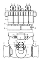
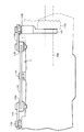
As shown in FIGS. 18 to 21, the
[0037]
A
[0038]
Further, the front
[0039]
As described above, the
[0040]
As shown in FIG. 6, the continuously
[0041]
As apparent from the above, in the rice transplanter provided with the hydraulic continuously
[0042]
In addition, the
[0043]
Further, a
[0044]
Further, the continuously
[0045]
Further, the drive system is arranged in the order of the continuously
[0046]
As shown in FIGS. 7, 13, and 14, the
[0047]
Further, the universal
[0048]
As shown in FIGS. 22 to 24, the
[0049]
Also, left and right
[0050]
Further, the
[0051]
As is clear from the above, in the rice transplanter that interlocks the steering handle 14 that is the steering operation unit and the left and
[0052]
Further, the
[0053]
【The invention's effect】
As apparent from the above embodiments, the present invention connects the
[0054]
Further, the accuracy of the side clutch operation can be improved.
[Brief description of the drawings]
FIG. 1 is an overall side view of a rice transplanter.
FIG. 2 is an overall plan view of a rice transplanter.
FIG. 3 is a side view of a traveling vehicle body.
FIG. 4 is a plan view of a traveling vehicle body.
FIG. 5 is a side view of the vehicle body frame.
FIG. 6 is an explanatory side view of a drive unit.
FIG. 7 is an explanatory plan view of a drive unit.
FIG. 8 is an explanatory side view of a side clutch operation system.
FIG. 9 is an explanatory plan view of a side clutch operation system.
FIG. 10 is a perspective explanatory view of a vehicle body.
FIG. 11 is a perspective explanatory view of a vehicle body.
FIG. 12 is a perspective explanatory view of a vehicle body.
FIG. 13 is an explanatory perspective view of a drive unit.
FIG. 14 is a perspective explanatory view of a lifting link part.
FIG. 15 is an explanatory diagram of an elevating link attaching portion.
FIG. 16 is a side view of a fuel tank installation.
FIG. 17 is a plan view of a fuel tank installation.
FIG. 18 is a cross-sectional explanatory view of a mission case.
FIG. 19 is a front explanatory view of a mission case.
FIG. 20 is an explanatory diagram of a planetary reduction gear mechanism.
FIG. 21 is an explanatory diagram of a travel output shaft portion.
FIG. 22 is a sectional view of a rear axle case portion.
FIG. 23 is an explanatory plan view of a cam member portion.
FIG. 24 is a front explanatory view of a cam member portion.
[Explanation of symbols]
7
129/130 Side clutch 138 Arm shaft (fulcrum shaft)
139 Roller (Roller mechanism)
140
Claims (1)
前記操向ハンドル14のクラッチ操作力を操作カム142及びローラ139機構を介して前記サイドクラッチ129,130に伝達させるように構成し、前記ローラ139を有するクラッチ操作アーム140の支点アーム軸138と操作カム142の支点軸141を前記リヤアクスルケース7に設け、
前記ミッションケース4にステアリングケース64を設け、操向ハンドル14操作と連動するステアリングアーム98が前記ステアリングケース64に配置され、前記ステアリングアーム98にロッド99・100を介して操作カム142を連結させたことを特徴とする田植機。 The planting portion 15 is connected to the rear side of the traveling vehicle 1 via the lifting link mechanism 26, the front wheel 6 is supported to the transmission case 4 via the front axle case 5, and the rear wheel case 7 behind the transmission case 4 is connected to the rear wheel. 8, in which the transmission case 4 and the rear axle case 7 are connected by a connecting frame 70, and the steering handle 14 and the left and right side clutches 129, 130 are connected to each other.
Wherein via the operating cam 142 and the roller 139 mechanism of the clutch operating force of the steering wheel 14 is configured to transmit to said side clutch 129, 130, operating as a fulcrum arm shaft 138 of the clutch operating arm 140 having the roller 139 provided fulcrum shaft 141 of the cam 142 to the rear axle case 7,
A steering case 64 is provided in the transmission case 4, and a steering arm 98 that is interlocked with the operation of the steering handle 14 is disposed on the steering case 64, and an operation cam 142 is connected to the steering arm 98 via rods 99 and 100. Rice transplanter characterized by that.
Priority Applications (1)
| Application Number | Priority Date | Filing Date | Title |
|---|---|---|---|
| JP2001152171A JP4733290B2 (en) | 2001-05-22 | 2001-05-22 | Rice transplanter |
Applications Claiming Priority (1)
| Application Number | Priority Date | Filing Date | Title |
|---|---|---|---|
| JP2001152171A JP4733290B2 (en) | 2001-05-22 | 2001-05-22 | Rice transplanter |
Publications (2)
| Publication Number | Publication Date |
|---|---|
| JP2002340021A JP2002340021A (en) | 2002-11-27 |
| JP4733290B2 true JP4733290B2 (en) | 2011-07-27 |
Family
ID=18996889
Family Applications (1)
| Application Number | Title | Priority Date | Filing Date |
|---|---|---|---|
| JP2001152171A Expired - Lifetime JP4733290B2 (en) | 2001-05-22 | 2001-05-22 | Rice transplanter |
Country Status (1)
| Country | Link |
|---|---|
| JP (1) | JP4733290B2 (en) |
Families Citing this family (1)
| Publication number | Priority date | Publication date | Assignee | Title |
|---|---|---|---|---|
| JP4585406B2 (en) * | 2005-08-18 | 2010-11-24 | ヤンマー株式会社 | Side clutch switching mechanism of riding type rice transplanter |
Citations (4)
| Publication number | Priority date | Publication date | Assignee | Title |
|---|---|---|---|---|
| JPS55100429A (en) * | 1979-01-26 | 1980-07-31 | Kubota Ltd | Clutch operator for movable work truck |
| JPS55119263U (en) * | 1979-02-16 | 1980-08-23 | ||
| JPS58118077U (en) * | 1982-02-05 | 1983-08-11 | セイレイ工業株式会社 | Transmission devices for tractors, etc. |
| JP2000350506A (en) * | 1999-06-09 | 2000-12-19 | Kubota Corp | Device for operating paddy working machine |
Family Cites Families (2)
| Publication number | Priority date | Publication date | Assignee | Title |
|---|---|---|---|---|
| JPS55119263A (en) * | 1979-03-05 | 1980-09-12 | Shimizu Mitsuru | Fluid shut-off device |
| JPS58118077A (en) * | 1981-12-29 | 1983-07-13 | Fanuc Ltd | Detecting system for loading of memory cassette |
-
2001
- 2001-05-22 JP JP2001152171A patent/JP4733290B2/en not_active Expired - Lifetime
Patent Citations (4)
| Publication number | Priority date | Publication date | Assignee | Title |
|---|---|---|---|---|
| JPS55100429A (en) * | 1979-01-26 | 1980-07-31 | Kubota Ltd | Clutch operator for movable work truck |
| JPS55119263U (en) * | 1979-02-16 | 1980-08-23 | ||
| JPS58118077U (en) * | 1982-02-05 | 1983-08-11 | セイレイ工業株式会社 | Transmission devices for tractors, etc. |
| JP2000350506A (en) * | 1999-06-09 | 2000-12-19 | Kubota Corp | Device for operating paddy working machine |
Also Published As
| Publication number | Publication date |
|---|---|
| JP2002340021A (en) | 2002-11-27 |
Similar Documents
| Publication | Publication Date | Title |
|---|---|---|
| JP4812201B2 (en) | Mobile farm machine | |
| JP4379763B2 (en) | Rice transplanter | |
| JP2585281Y2 (en) | Electric farm tractor | |
| JP4733290B2 (en) | Rice transplanter | |
| JP4636578B2 (en) | Rice transplanter | |
| JP5166362B2 (en) | Rice transplanter | |
| JP4753269B2 (en) | Rice transplanter | |
| JP5653962B2 (en) | Rice transplanter | |
| JP5008109B2 (en) | Rice transplanter | |
| JP4678745B2 (en) | Rice transplanter | |
| JP4739610B2 (en) | Mobile farm machine | |
| JP5246902B2 (en) | Rice transplanter | |
| JP4753337B2 (en) | Work vehicle | |
| JP5246886B2 (en) | Rice transplanter | |
| JP2002335719A (en) | Rice transplanter | |
| JP2004019891A (en) | Working vehicle | |
| JP3437650B2 (en) | Moving agricultural machine | |
| JP4789229B2 (en) | Rice transplanter | |
| JP3227775B2 (en) | Seedling machine | |
| JP4836157B2 (en) | Rice transplanter | |
| JP3360188B2 (en) | Moving agricultural machine | |
| JP3248714B2 (en) | Riding agricultural work machine | |
| JP2569442Y2 (en) | Walking rice transplanter | |
| JP2004161045A (en) | Working vehicle | |
| JP2004065012A (en) | Traveling vehicle |
Legal Events
| Date | Code | Title | Description |
|---|---|---|---|
| RD04 | Notification of resignation of power of attorney |
Free format text: JAPANESE INTERMEDIATE CODE: A7424 Effective date: 20040610 |
|
| RD04 | Notification of resignation of power of attorney |
Free format text: JAPANESE INTERMEDIATE CODE: A7424 Effective date: 20040810 |
|
| A072 | Dismissal of procedure [no reply to invitation to correct request for examination] |
Free format text: JAPANESE INTERMEDIATE CODE: A073 Effective date: 20040921 |
|
| A621 | Written request for application examination |
Free format text: JAPANESE INTERMEDIATE CODE: A621 Effective date: 20080424 |
|
| A521 | Written amendment |
Free format text: JAPANESE INTERMEDIATE CODE: A821 Effective date: 20080806 |
|
| RD02 | Notification of acceptance of power of attorney |
Free format text: JAPANESE INTERMEDIATE CODE: A7422 Effective date: 20080806 |
|
| A521 | Written amendment |
Free format text: JAPANESE INTERMEDIATE CODE: A821 Effective date: 20080806 |
|
| A711 | Notification of change in applicant |
Free format text: JAPANESE INTERMEDIATE CODE: A712 Effective date: 20090723 |
|
| A131 | Notification of reasons for refusal |
Free format text: JAPANESE INTERMEDIATE CODE: A131 Effective date: 20100908 |
|
| A977 | Report on retrieval |
Free format text: JAPANESE INTERMEDIATE CODE: A971007 Effective date: 20100909 |
|
| A521 | Written amendment |
Free format text: JAPANESE INTERMEDIATE CODE: A523 Effective date: 20101104 |
|
| TRDD | Decision of grant or rejection written | ||
| A01 | Written decision to grant a patent or to grant a registration (utility model) |
Free format text: JAPANESE INTERMEDIATE CODE: A01 Effective date: 20110406 |
|
| A01 | Written decision to grant a patent or to grant a registration (utility model) |
Free format text: JAPANESE INTERMEDIATE CODE: A01 |
|
| A61 | First payment of annual fees (during grant procedure) |
Free format text: JAPANESE INTERMEDIATE CODE: A61 Effective date: 20110422 |
|
| FPAY | Renewal fee payment (event date is renewal date of database) |
Free format text: PAYMENT UNTIL: 20140428 Year of fee payment: 3 |
|
| R150 | Certificate of patent or registration of utility model |
Free format text: JAPANESE INTERMEDIATE CODE: R150 Ref document number: 4733290 Country of ref document: JP Free format text: JAPANESE INTERMEDIATE CODE: R150 |
|
| R250 | Receipt of annual fees |
Free format text: JAPANESE INTERMEDIATE CODE: R250 |
|
| EXPY | Cancellation because of completion of term |