JP4678745B2 - Rice transplanter - Google Patents
Rice transplanter Download PDFInfo
- Publication number
- JP4678745B2 JP4678745B2 JP2001150918A JP2001150918A JP4678745B2 JP 4678745 B2 JP4678745 B2 JP 4678745B2 JP 2001150918 A JP2001150918 A JP 2001150918A JP 2001150918 A JP2001150918 A JP 2001150918A JP 4678745 B2 JP4678745 B2 JP 4678745B2
- Authority
- JP
- Japan
- Prior art keywords
- frame
- planting
- vehicle body
- fuel tank
- seat
- Prior art date
- Legal status (The legal status is an assumption and is not a legal conclusion. Google has not performed a legal analysis and makes no representation as to the accuracy of the status listed.)
- Expired - Fee Related
Links
Images


Description
【0001】
【発明の属する技術分野】
本発明は苗載台及び苗植付爪を備えて連続的に苗植作業を行う田植機に関する。
【0002】
【発明が解決しようとする課題】
従来、燃料タンクはエンジンの上方近傍位置などに配設する構造のため、その設置スペースも他の部品の制約を受けて、大容量の燃料タンクの設置を不可能なものとさせていた。また、大容量の燃料タンクをエンジン上方に設けた場合運転席から前方の視認性も悪い。
【0003】
【課題を解決するための手段】
したがって本発明は、エンジンを搭載する車体フレームと、フロントアクスルケースに支持させる前輪と、リヤアクスルケースに支持させる後輪と、前記車体フレームの後側に昇降リンク機構を介して昇降可能に設ける植付部と、前記植付部を昇降する植付昇降シリンダと、前記車体フレーム前部のミッションケースに前記車体フレーム後部の前記リヤアクスルケースを連結させる連結フレームとを備え、作業者が搭乗するステップのうち、ステップ立上り部後方の前記ステップ後部の上面側に運転席を配置する田植機において、前記ステップ後側のステップ立上り部から前記運転席下方にかけて、前記ステップ後部の下側に前記車体フレームの後部フレームを介して燃料タンクを設け、前記ステップと前記連結フレームと前記車体フレームとによって前記燃料タンクを囲むように構成する構造であって、前記連結フレームの上面側に前記植付昇降シリンダの基端側を連結し、前記運転席と前記植付昇降シリンダと前記連結フレームとの間に前記燃料タンクを配設し、前記後部フレームの左右側フレーム間に連結したパイプフレームに取付部材を介して前記燃料タンクを取外し可能に固定させるように構成したもので、運転席下側のスペースを有効利用して大容量の燃料タンクを容易に設置できると共に、前記燃料タンクを機体中央側に配置でき、燃料の増減による機体の前後及び左右バランスの悪化を防止して機体の安定性を向上させるものである。
【0004】
また、運転席・昇降シリンダ・燃料タンクをコンパクトに組込み、機体の小型化を図るものである。
【0005】
さらに、連結フレームによって機体下方の障害物などから燃料タンクを保護して、燃料タンクの損傷防止を図るものである。
【0006】
【発明の実施の形態】
以下、本発明の実施例を図面に基づいて詳述する。図1は全体の側面図、図2は同平面図、図3は車体フレームの側面図、図4は同平面図を示し、図中1は作業者が搭乗する走行車であり、エンジン2を車体フレーム3に搭載させ、ミッションケース4側方にフロントアクスルケース5を介して水田走行用前輪6を支持させると共に、前記ミッションケース4後方のリヤアクスルケース7に水田走行用後輪8を支持させる。そして前記エンジン2等を覆うボンネット9両側に予備苗載台10を取付けると共に、作業者が搭乗する車体カバー11によって前記ミッションケース4等を覆い、前記車体カバー11後側上方にシートフレーム12を介して運転席13を取付け、その運転席13の前方で前記ボンネット9後部に操向ハンドル14を設ける。
【0007】
また、図中15は5条植え用の苗載台16並びに複数の苗植付爪17などを具備する植付部であり、前高後低の合成樹脂製の前傾式苗載台16を下部レール18及びガイドレール19を介して植付ケース20に左右往復摺動自在に支持させると共に、一方向に等速回転させるロータリケース21を前記植付ケース20に支持させ、該ケース21の回転軸芯を中心に対称位置に一対の爪ケース22・22を配設し、その爪ケース22・22先端に苗植付爪17・17を取付ける。
【0008】
また、前記植付ケース20前側のヒッチブラケット23をトップリンク24及びロワーリンク25を含む昇降リンク機構26を介し走行車1後側に連結させ、前記リンク機構26を介して植付部15を昇降させる油圧昇降シリンダ27をロワーリンク25に連結させ、前記前後輪6・8を走行駆動して移動すると同時に、左右に往復摺動させる苗載台16から一株分の苗を植付爪17によって取出し、連続的に苗植え作業を行うように構成する。
【0009】
また、図中28は主変速レバー、29は植付昇降レバー、30はブレーキペダル、31はアクセルペダル、32はデフロックペダル、33は感度調節レバー、34は植付部15任意高さ位置に停止させるストップレバー、35はユニットクラッチレバー35であり、操向ハンドル14位置近傍に主変速及び昇降レバー28・29やブレーキ及びアクセルペダル30・31を配設すると共に、運転席13位置近傍に感度調節及びストップ及びユニットクラッチレバー33・34・35やデフロックペダル32を配設している。
【0010】
さらに、図中36は1条分均平用センタフロート、37は2条分均平用サイドフロート、38は肥料ホッパ39内の肥料を送風機40の送風力でフレキシブル形搬送ホース41を介しフロート36・37の側条作溝器42に排出させる5条用側条施肥機である。
【0011】
図3乃至図5に示す如く、前記車体フレーム3は前部フレーム43と中間フレーム44と後部フレーム45とに3分割させ、前部フレーム43にエンジン2を、中間フレーム44にフロントアクスルケース5を、後部フレーム45にリヤアクスルケース7及びエンジン2に燃料を供給する燃料タンク46などを設けるもので、前部フレーム43は左右側フレーム43a・43bの前端を前フレーム47で、中間をベースフレーム48で相互に連結させて平面視4角枠状に形成し、左右側フレーム43a・43bの固定ブラケット49とベースフレーム48に防振ゴムを介しエンジン2を上載させるように構成している。
【0012】
また、前記後部フレーム45は左右側フレーム45a・45bの中間立上り部50間をパイプフレーム51と門形フレーム52とで略平行に連結させると共に、リヤアクスルケース7に左右下端を固設する門形フレーム53に左右側フレーム45a・45bの後端を一体連結させ、左右側フレーム45a・45bの立上り部50間に燃料タンク46を配設するように構成している。
【0013】
さらに、前記中間フレーム44は、前部左右側フレーム43a・43bの後端と後部左右側フレーム45a・45bの前端に左右中間フレーム44の前後端をボルト54を介し取外し自在に固定させると共に、左右中間フレーム44の下面にボルト55を介し左右フロントアクスルケース5を取外し自在に固定させ、前記ミッションケース4に左右フロントアクスルケース5を接続固定させるように構成している。
【0014】
また、前部の左右側フレーム43a・43bの断面積を後部の左右側フレーム45a・45bより大に形成して、重量物のエンジン2を搭載する前部フレーム43を堅固なものに形成すると共に、前部フレーム43に比べ強度を必要としない中間フレーム44や後部フレーム45を軽量に形成して、前後バランスや強度バランスを良好とさせるように構成している。さらに分割させた前部フレーム43・中間フレーム44・後部フレーム45にエンジン2・フロントアクスルケース5及びミッションケース4・リヤアクスルケース7などをそれぞれ分割させた状態で組立て一体化させることによって、組立性やメンテナンス性を向上させることができる。
【0015】
そして、前部フレーム43の前後外側と後部フレーム45の前外側にステップフレーム56・57・58を突設させ、これらフレーム56・57・58の外側間を前パイプ59で連結させ、後部フレーム45の立上り部50の上側間にブラケット60を介し固設するステップフレーム61と、前記フレーム58の左右外側とに左右後パイプ62を連結させ、左右後パイプ62の後側間を横フレーム62aで連結させ、門形フレーム53の上側水平部と横フレーム62aとステップフレーム61の略中央部を前後方向の2本のフレーム62bで連結させ、後パイプ62前側の低位置の水平部に足踏台63を着脱自在にボルト止め固定させ、前記門形フレーム52とステップフレーム61とにシートフレーム12を介し運転席13を支持させると共に、各フレーム56・57・58・61の上面に車体カバー11を取外し自在に固定保持させるように構成している。
【0016】
図6乃至図13にも示す如く、前記ミッションケース4は前面左側にパワーステアリングケース64、右側に油圧式無段変速機構(HST)65をそれぞれ配設させ、無段変速機構65の変速入力軸66を車体前方向に突出させ、エンジン2下側で前後方向のカウンタ軸67に入力軸66を連結させると共に、エンジン出力軸68に伝達ベルト69を介し前記カウンタ軸67を連結させて、エンジン出力を無段変速機構65を介しミッションケース4に伝達するように構成している。
【0017】
また、前記ミッションケース4とリヤアクスルケース7とは車体の中心ライン上でパイプ製の連結フレーム70で一体連結させ、ミッションケース4後方に後走行出力軸71及びPTO出力軸72を突出させ、リヤアクスルケース7前方に突出させる入力軸73に伝達軸74を介し前記出力軸71を連結させ、またリヤアクスルケース7上部の軸受75に設ける中介軸76に自在継手軸77を介し前記PTO出力軸72を連結させ、前記植付ケース20の入力軸に自在継手軸78を介し中介軸76を連結させるように構成している。
【0018】
また、前記連結フレーム70はフロント及びリヤアクスルケース5・7に接続させ、連結フレーム70の後部上面にシリンダ取付座79を固設して、車体の中心ライン上で昇降シリンダ27の基端を取付座79に支持させるように構成している。なお前記連結フレーム70内を昇降シリンダ27などの油圧の油タンクに用いても良く、またフロント及びアクスルケース5・7に連結フレーム70を連通接続させて、これらケース5・7や連結フレーム70内を油タンクに用いても良い。
【0019】
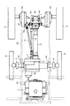
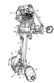
図14、図15にも示す如く、前記リヤアクスルケース7は平面視で門形に形成し、ケース7両側の左右ギヤケース部80外面にロープフック81を固設すると共に、左右ギヤケース部80間に形成される門形空間部82に前記ロワーリンク25を配設させるもので、アクスルケース7の中央上面に固定手段であるボルト83を介しリンク軸受部材84を固定させ、リンク軸受部材84に前支点軸85を介しロワーリンク25の前端側を連結させ、昇降シリンダ27のピストンロッド86先端をロワーリンク25に固定する枢着板25aに連結させ、前記ヒッチブラケット23に後支点軸88を介しロワーリンク25の後端側を連結させ、門形フレーム53とヒッチブラケット23間を連結するトップリンク24とによって植付部15の昇降を行うように構成している。
【0020】
前記ロワーリンク25は4角パイプで形成し、前後支点軸85・88が嵌合する支点筒軸89・90をロワーリンク25の前後端側に設けて、部品の軽量化と、ローリングなどに対する剛性向上を図るように構成している。
【0021】
図16、図17にも示す如く、前記燃料タンク46は運転席13下方で後部左右側フレーム45a・45bの立上り部50間の余剰スペースに配設させるもので、前記パイプフレーム51の取付部材91にボルト92を介し取外し自在にタンク46前端を固定させると共に、前記ステップフレーム61の下側にボルト93を介し固設するタンク取付板94に、タンク46中間の左右突出縁46aをボルト95を介し固定させて、車体カバー11後側の立上り部11a内の車体中心ライン上で運転席13と連結フレーム70と左右側フレーム45a・45bとで囲まれたデッドスペースにバランス良好にタンク46を配設するように構成している。
【0022】
図8、図9にも示す如く、前記パワーステアリングケース64は上側にトルクジェネレータ部96を下側に遊星減速ギヤ機構部97を有して縦長状に設け、隣接の変速機構65との左右設置巾を小とさせコンパクトな配置を可能とさせて、左右前輪6の狭いトレッドにも良好に対応させるように構成している。
【0023】
そして、前記パワーステアリングケース64下側のステアリングアーム98に第1及び第2ロッド99・100を介しリヤアクスルケース7内の左右サイドクラッチを操作するカム部材101を連結させるもので、連結フレーム70を上下方向に貫通させる縦軸102の上下突出端に上下揺動アーム103・104を固定させ、連結フレーム70より右側位置でステアリングアーム98と下揺動アーム104間を第1ロッド99で、また上揺動アーム103とカム部材101間を第2ロッド100で連結させて、操向ハンドル14操作に連動させた左右サイドクラッチの入切動作を行わせるように構成している。
【0024】
上記からも明らかなように、機体を構成する車体フレーム3を前部フレーム43と中間フレーム44と後部フレーム45とに3分割させたもので、車体フレーム3を長尺一体構造とするものに比べ、取扱及び組立性を良好とさせることができる。
【0025】
また、中間フレーム44にフロントアクスルケース5を連結させるもので、エンジン2などは前部フレーム43に連結させたままの状態でミッションケース4とフロントアクスルケース5とを一体とさせた取付け及び取外しなどを容易に可能とさせて、ミッションケース4及びフロントアクスルケース5のメンテナンス性を向上させることができる。
【0026】
さらに、前部フレーム43の断面積を後部フレーム45より大に形成すると共に、エンジン2を前部フレーム43に支持させるもので、重量物のエンジン2を前部フレーム43に強度良好に支持させると共に、機体後側に装備させる植付部15との前後バランスを良好とさせて、機体の安定性を向上させることができる。
【0027】
また、機体前側のミッションケース4と機体後側のリヤアクスルケース7とを一体連結させる連結フレーム70を設けると共に、植付部15を昇降させる植付昇降シリンダ27を前記連結フレーム70に取付けるもので、車体フレーム3にシリンダ荷重がかかるのを防止し、車体フレーム3のシンプル及び軽量化を容易に可能とさせると共に、シリンダ荷重を連結フレーム70を介し前後輪6・8に良好に分担支持させて昇降シリンダ27の取付強度を良好とさせ、大重量の昇降シリンダ27の取付も容易に可能とさせることができる。
【0028】
さらに、連結フレーム70の上面に植付昇降シリンダ27の取付座79を設けるもので、連結フレーム70に強度良好に昇降シリンダ27を支持させると共に、機体下方の障害物より連結フレーム70で昇降シリンダ27を損傷なく保護してシリンダ27性能を安定保持させることができる。
【0029】
またさらに、連結フレーム70上方でミッションケース4とリヤアクスルケース7とを後部フレーム45を介して連結させて、ミッションケース4とリヤアクスルケース7と連結フレーム70と後部フレーム45(門形フレーム53も含む)とでトラス構造に設けたもので、これらミッションケース4とリヤアクスルケース7と連結フレーム70と後部フレーム45とで形成する本機フレーム構造の軽量化と剛性の向上化を容易に図ることができる。
【0030】
また、ステップである車体カバー11後側のカバー立上り部11aから運転席13下方にかけての車体カバー11内に燃料タンク46を配設させたもので、運転席13下側のデッドスペースを有効利用し大容量の燃料タンク46の設置を容易に可能とさせ、燃料のベーパーロック現象を防止してヒートバランスを良好とさせると共に、燃料タンク46を機体の略中央位置に配置させて燃料の増減による機体の前後及び左右バランスの悪化を防止して機体の安定性を向上させることができる。
【0031】
さらに、燃料タンク46に対し植付部15を昇降する植付昇降シリンダ27と運転席13とを側面視で上下方向にラップさせたもので、これら運転席13・昇降シリンダ27・燃料タンク46の前後長を小とさせるコンパクトな機体組込みを容易に可能とさせて、機体の小型化を図ることができる。
【0032】
連結させる連結フレーム70上方に燃料タンク46を配設させたもので、機体下方の障害物などから連結フレーム70によって燃料タンク46を保護して、燃料タンク46の損傷防止を図ることができる。
【0033】
また、本機側に昇降リンク機構26を介し植付部15を昇降自在に支持させた田植機において、昇降リンク機構26を構成するロワーリンク25の本機側取付部であるリンク軸受部材84をリヤアクスルケース7に設けたもので、植付上昇時などにロワーリンク25に加わる植付部15の荷重を堅固なリヤアクスルフレーム7に良好に支持させて、植付部15の支持強度を向上させ、車体フレーム3にロワーリンク25を支持させる従来構造に比べ、車体フレーム3の軽量化を容易に可能とさせると共に、ロワーリンク25の取外し及び取付けを容易とさせてロワーリンク25の交換などのメンテナンス性を向上させることができる。
【0034】
さらに、ロワーリンク25にロワーリンク支点部である筒軸89を一体的に形成すると共に、リヤアクスルケース7に取付部84を介しロワーリンク25前側のロワーリンク支点筒軸89を回動自在に支持させたもので、部品点数を削減した簡単構造のものでリヤアクスルケース7にロワーリンク25を良好に支持させて、植付部15の確実な保持を可能とさせることができる。
【0035】
また、リヤアクスルケース7を平面視門形に形成すると共に、リヤアクスルケース7の門形空間部82にロワーリンク支点筒軸89を配置させたもので、ロワーリンク支点筒軸89を後輪8車軸に近接させ、本機と植付部15を最大に近づけて、田植機体全長の縮小化を容易に可能とさせて機体の小型化を図ることができる。
【0036】
さらに、ロワーリンク25を単一のパイプ部材で形成すると共に、該パイプ部材の前後端部にロワーリンク25の前後ロワーリンク支点筒軸89・90を設けたもので、本機及び植付部15に対するロワーリンク25の連結構造の簡略化を図ると共に、ロワーリンク25の軽量化を図って機体の小型軽量化を容易に可能とさせることができる。
【0037】
【発明の効果】
以上実施例から明らかなように本発明は、エンジン2を搭載する車体フレーム3と、フロントアクスルケース5に支持させる前輪6と、リヤアクスルケース7に支持させる後輪8と、車体フレーム3の後側に昇降リンク機構26を介して昇降可能に設ける植付部15と、植付部15を昇降する植付昇降シリンダ27と、車体フレーム3前部のミッションケース4に車体フレーム3後部のリヤアクスルケース7を連結させる連結フレーム70とを備え、作業者が搭乗するステップ(車体カバー)11のうち、ステップ立上り部後方の前記ステップ11後部の上面側に運転席13を配置する田植機において、前記ステップ11後側のステップ立上り部から前記運転席13下方にかけて、ステップ11後部の下側に車体フレーム3の後部フレーム45を介して燃料タンク46を設け、ステップ11と連結フレーム70と車体フレーム3とによって燃料タンク46を囲むように構成する構造であって、連結フレーム70の上面側に植付昇降シリンダ27の基端側を連結し、運転席13と植付昇降シリンダ27と連結フレーム70との間に燃料タンク46を配設し、後部フレーム45の左右側フレーム45a・45b間に連結したパイプフレーム51に取付部材91を介して燃料タンク46を取外し可能に固定させるように構成したものであるから、運転席13下側のスペースを有効利用して大容量の燃料タンク46を容易に設置できると共に、燃料タンク46を機体中央側に配置でき、燃料の増減による機体の前後又は左右バランスの悪化を防止して機体の安定性を向上させることができるものである。
【0038】
また、運転席13・昇降シリンダ27・燃料タンク46をコンパクトに組込むことができ、機体の小型化を図ることができるものである。
【0039】
さらに、連結フレーム70によって機体下方の障害物などから燃料タンク46を保護でき、燃料タンク46の損傷防止を図って、耐久性を向上させることができるものである。
【図面の簡単な説明】
【図1】田植機の全体側面図。
【図2】田植機の全体平面図。
【図3】走行車体の側面図。
【図4】走行車体の平面図。
【図5】車体フレームの側面図。
【図6】駆動部の側面説明図。
【図7】駆動部の平面説明図。
【図8】サイドクラッチ操作系の側面説明図。
【図9】サイドクラッチ操作系の平面説明図。
【図10】車体の斜視説明図。
【図11】車体の斜視説明図。
【図12】車体の斜視説明図。
【図13】駆動部の斜視説明図。
【図14】昇降リンク部の斜視説明図。
【図15】昇降リンク取付部の説明図。
【図16】燃料タンク設置側面図。
【図17】燃料タンク設置平面図。
【符号の説明】
4 ミッションケース
7 リヤアクスルケース
11 車体カバー(ステップ)
11a 立上り部
13 運転席
15 植付部
27 昇降シリンダ
46 燃料タンク
70 連結フレーム[0001]
BACKGROUND OF THE INVENTION
The present invention relates to a rice transplanter that includes a seedling stage and a seedling planting claw and performs seedling planting work continuously.
[0002]
[Problems to be solved by the invention]
Conventionally, since the fuel tank is arranged near the upper position of the engine, the installation space is also restricted by other parts, making it impossible to install a large capacity fuel tank. In addition, when a large-capacity fuel tank is provided above the engine, visibility forward from the driver's seat is poor.
[0003]
[Means for Solving the Problems]
Therefore, the present invention provides a vehicle body frame on which an engine is mounted, a front wheel supported by a front axle case, a rear wheel supported by a rear axle case, and a planting provided on the rear side of the vehicle body frame via a lifting link mechanism. A step in which an operator rides, and a connecting frame for connecting the rear axle case at the rear part of the vehicle body frame to a transmission case at the front part of the vehicle body frame. In the rice transplanter in which a driver's seat is arranged on the upper surface side of the step rear portion behind the step rising portion , the rear frame of the vehicle body frame is located below the step rear portion from the step rising portion on the rear side of the step to the lower side of the driver seat. A fuel tank is provided via the step, the connecting frame, and the vehicle body frame. A base end side of the planting lift cylinder is connected to the upper surface side of the connection frame, and the driver seat, the planting lift cylinder, and the connection frame are connected to each other. The fuel tank is disposed in between, and the fuel tank is detachably fixed to a pipe frame connected between the left and right frames of the rear frame via an attachment member. A large-capacity fuel tank can be easily installed using space effectively, and the fuel tank can be placed in the center of the aircraft, preventing the deterioration of the balance between the front and rear and the left and right of the aircraft due to increase and decrease of fuel, and improving the stability of the aircraft It is to improve.
[0004]
In addition, the driver's seat, lifting cylinder, and fuel tank are compactly incorporated to reduce the size of the aircraft.
[0005]
In addition, the fuel tank is protected from obstacles and the like below the fuselage by the connecting frame to prevent damage to the fuel tank.
[0006]
DETAILED DESCRIPTION OF THE INVENTION
Embodiments of the present invention will be described below in detail with reference to the drawings. 1 is a side view of the whole, FIG. 2 is a plan view of the same, FIG. 3 is a side view of a vehicle body frame, FIG. 4 is a plan view of the body, and 1 is a traveling vehicle on which an operator rides. Mounted on the vehicle body frame 3, the
[0007]
In the figure,
[0008]
Further, the
[0009]
In the figure, 28 is a main transmission lever, 29 is a planting lift lever, 30 is a brake pedal, 31 is an accelerator pedal, 32 is a differential lock pedal, 33 is a sensitivity adjustment lever, and 34 is stopped at an arbitrary height position of the
[0010]
Further, in the figure, 36 is a center float for leveling of one strip, 37 is a side float for leveling of two strips, 38 is a
[0011]
As shown in FIGS. 3 to 5, the vehicle body frame 3 is divided into a
[0012]
The
[0013]
Further, the
[0014]
In addition, the front left and
[0015]
Then,
[0016]
As shown in FIGS. 6 to 13, the
[0017]
Further, the
[0018]
The connecting
[0019]
As shown in FIGS. 14 and 15, the
[0020]
The
[0021]
As shown in FIGS. 16 and 17, the
[0022]
As shown in FIGS. 8 and 9, the
[0023]
The
[0024]
As is clear from the above, the vehicle body frame 3 constituting the airframe is divided into three parts, a
[0025]
Further, the
[0026]
Further, the cross-sectional area of the
[0027]
In addition, a connecting
[0028]
Further, a mounting
[0029]
Further, the
[0030]
Further, a
[0031]
Further, the
[0032]
The
[0033]
Further, in the rice transplanter in which the
[0034]
Further, a
[0035]
Further, the
[0036]
Further, the
[0037]
【The invention's effect】
As is apparent from the above-described embodiments, the present invention includes a vehicle body frame 3 on which the
[0038]
Further, the driver's
[0039]
Furthermore, the
[Brief description of the drawings]
FIG. 1 is an overall side view of a rice transplanter.
FIG. 2 is an overall plan view of a rice transplanter.
FIG. 3 is a side view of a traveling vehicle body.
FIG. 4 is a plan view of a traveling vehicle body.
FIG. 5 is a side view of the vehicle body frame.
FIG. 6 is an explanatory side view of a drive unit.
FIG. 7 is an explanatory plan view of a drive unit.
FIG. 8 is an explanatory side view of a side clutch operation system.
FIG. 9 is an explanatory plan view of a side clutch operation system.
FIG. 10 is a perspective explanatory view of a vehicle body.
FIG. 11 is a perspective explanatory view of a vehicle body.
FIG. 12 is a perspective explanatory view of a vehicle body.
FIG. 13 is an explanatory perspective view of a drive unit.
FIG. 14 is a perspective explanatory view of a lifting link part.
FIG. 15 is an explanatory diagram of an elevating link attaching portion.
FIG. 16 is a side view of a fuel tank installation.
FIG. 17 is a plan view of a fuel tank installation.
[Explanation of symbols]
4
Claims (1)
前記ステップ後側のステップ立上り部から前記運転席下方にかけて、前記ステップ後部の下側に前記車体フレームの後部フレームを介して燃料タンクを設け、前記ステップと前記連結フレームと前記車体フレームとによって前記燃料タンクを囲むように構成する構造であって、
前記連結フレームの上面側に前記植付昇降シリンダの基端側を連結し、前記運転席と前記植付昇降シリンダと前記連結フレームとの間に前記燃料タンクを配設し、前記後部フレームの左右側フレーム間に連結したパイプフレームに取付部材を介して前記燃料タンクを取外し可能に固定させるように構成したことを特徴とする田植機。A vehicle body frame on which the engine is mounted, a front wheel supported on the front axle case, a rear wheel supported on the rear axle case, a planting portion provided on the rear side of the vehicle body frame via a lifting link mechanism, and the planting portion comprising a planting lift cylinder for lifting the biasing portion, and a connecting frame for connecting the rear axle case of the vehicle frame rear portion on the body frame front portion of the transmission case, of the steps the operator rides, step rising portion rearward In the rice transplanter which arranges the driver's seat on the upper surface side of the rear part of the step ,
A fuel tank is provided via a rear frame of the vehicle body frame below the step rear portion from the step rising portion on the rear side of the step to the lower side of the driver's seat, and the fuel is formed by the step, the connecting frame, and the vehicle body frame. A structure configured to surround the tank,
A base end side of the planting elevating cylinder is coupled to an upper surface side of the coupling frame, the fuel tank is disposed between the driver's seat, the planting elevating cylinder, and the coupling frame, and left and right of the rear frame A rice transplanter characterized in that the fuel tank is detachably fixed to a pipe frame connected between side frames via an attachment member.
Priority Applications (1)
| Application Number | Priority Date | Filing Date | Title |
|---|---|---|---|
| JP2001150918A JP4678745B2 (en) | 2001-05-21 | 2001-05-21 | Rice transplanter |
Applications Claiming Priority (1)
| Application Number | Priority Date | Filing Date | Title |
|---|---|---|---|
| JP2001150918A JP4678745B2 (en) | 2001-05-21 | 2001-05-21 | Rice transplanter |
Publications (2)
| Publication Number | Publication Date |
|---|---|
| JP2002337557A JP2002337557A (en) | 2002-11-27 |
| JP4678745B2 true JP4678745B2 (en) | 2011-04-27 |
Family
ID=18995859
Family Applications (1)
| Application Number | Title | Priority Date | Filing Date |
|---|---|---|---|
| JP2001150918A Expired - Fee Related JP4678745B2 (en) | 2001-05-21 | 2001-05-21 | Rice transplanter |
Country Status (1)
| Country | Link |
|---|---|
| JP (1) | JP4678745B2 (en) |
Citations (7)
| Publication number | Priority date | Publication date | Assignee | Title |
|---|---|---|---|---|
| JPH0569339U (en) * | 1991-04-02 | 1993-09-21 | 三菱農機株式会社 | Tractor fuel tank |
| JPH05344809A (en) * | 1992-06-12 | 1993-12-27 | Yanmar Agricult Equip Co Ltd | Riding agricultural working machine |
| JPH06107008A (en) * | 1992-09-30 | 1994-04-19 | Mazda Motor Corp | Supporting structure for vehicle driving device |
| JPH11243725A (en) * | 1998-03-04 | 1999-09-14 | Mitsubishi Agricult Mach Co Ltd | Transplanter |
| JPH11310042A (en) * | 1998-04-28 | 1999-11-09 | Yanmar Agricult Equip Co Ltd | Small passenger working machine |
| JP2000152709A (en) * | 1999-01-01 | 2000-06-06 | Yanmar Agricult Equip Co Ltd | Transmission arranging structure for riding type rice plant transplanter |
| JP2000177650A (en) * | 1998-12-16 | 2000-06-27 | Mitsubishi Agricult Mach Co Ltd | Traveling work vehicle |
-
2001
- 2001-05-21 JP JP2001150918A patent/JP4678745B2/en not_active Expired - Fee Related
Patent Citations (7)
| Publication number | Priority date | Publication date | Assignee | Title |
|---|---|---|---|---|
| JPH0569339U (en) * | 1991-04-02 | 1993-09-21 | 三菱農機株式会社 | Tractor fuel tank |
| JPH05344809A (en) * | 1992-06-12 | 1993-12-27 | Yanmar Agricult Equip Co Ltd | Riding agricultural working machine |
| JPH06107008A (en) * | 1992-09-30 | 1994-04-19 | Mazda Motor Corp | Supporting structure for vehicle driving device |
| JPH11243725A (en) * | 1998-03-04 | 1999-09-14 | Mitsubishi Agricult Mach Co Ltd | Transplanter |
| JPH11310042A (en) * | 1998-04-28 | 1999-11-09 | Yanmar Agricult Equip Co Ltd | Small passenger working machine |
| JP2000177650A (en) * | 1998-12-16 | 2000-06-27 | Mitsubishi Agricult Mach Co Ltd | Traveling work vehicle |
| JP2000152709A (en) * | 1999-01-01 | 2000-06-06 | Yanmar Agricult Equip Co Ltd | Transmission arranging structure for riding type rice plant transplanter |
Also Published As
| Publication number | Publication date |
|---|---|
| JP2002337557A (en) | 2002-11-27 |
Similar Documents
| Publication | Publication Date | Title |
|---|---|---|
| JP4812201B2 (en) | Mobile farm machine | |
| JP4636578B2 (en) | Rice transplanter | |
| JP4379763B2 (en) | Rice transplanter | |
| JP4753269B2 (en) | Rice transplanter | |
| JP4678745B2 (en) | Rice transplanter | |
| JP5008109B2 (en) | Rice transplanter | |
| JP5246886B2 (en) | Rice transplanter | |
| JP4733290B2 (en) | Rice transplanter | |
| JP5246902B2 (en) | Rice transplanter | |
| JP5166362B2 (en) | Rice transplanter | |
| JP5653962B2 (en) | Rice transplanter | |
| JP4739610B2 (en) | Mobile farm machine | |
| JP3657394B2 (en) | Rice transplanter | |
| JP2002335719A (en) | Rice transplanter | |
| JP5019675B2 (en) | Rice transplanter | |
| JP3393605B2 (en) | Riding rice transplanter | |
| JP4002029B2 (en) | Rice transplanter | |
| JPS5918946Y2 (en) | Agricultural index vehicle | |
| JPH0713447Y2 (en) | Rice transplanter | |
| JP3091987B2 (en) | Rice transplanter | |
| JP3742192B2 (en) | Rice transplanter | |
| JP2525581Y2 (en) | Rice transplanter power transmission | |
| JP3980790B2 (en) | Rice transplanter | |
| JPH0639536Y2 (en) | Rice transplanter | |
| JP3509921B2 (en) | Passenger management machine |
Legal Events
| Date | Code | Title | Description |
|---|---|---|---|
| RD04 | Notification of resignation of power of attorney |
Free format text: JAPANESE INTERMEDIATE CODE: A7424 Effective date: 20040610 |
|
| RD04 | Notification of resignation of power of attorney |
Free format text: JAPANESE INTERMEDIATE CODE: A7424 Effective date: 20040810 |
|
| A072 | Dismissal of procedure |
Free format text: JAPANESE INTERMEDIATE CODE: A073 Effective date: 20040921 |
|
| A621 | Written request for application examination |
Free format text: JAPANESE INTERMEDIATE CODE: A621 Effective date: 20080424 |
|
| A521 | Written amendment |
Free format text: JAPANESE INTERMEDIATE CODE: A821 Effective date: 20080806 |
|
| RD02 | Notification of acceptance of power of attorney |
Free format text: JAPANESE INTERMEDIATE CODE: A7422 Effective date: 20080806 |
|
| A711 | Notification of change in applicant |
Free format text: JAPANESE INTERMEDIATE CODE: A712 Effective date: 20090723 |
|
| A977 | Report on retrieval |
Free format text: JAPANESE INTERMEDIATE CODE: A971007 Effective date: 20100527 |
|
| A131 | Notification of reasons for refusal |
Free format text: JAPANESE INTERMEDIATE CODE: A131 Effective date: 20100602 |
|
| A521 | Written amendment |
Free format text: JAPANESE INTERMEDIATE CODE: A523 Effective date: 20100802 |
|
| A131 | Notification of reasons for refusal |
Free format text: JAPANESE INTERMEDIATE CODE: A131 Effective date: 20101013 |
|
| A521 | Written amendment |
Free format text: JAPANESE INTERMEDIATE CODE: A523 Effective date: 20101210 |
|
| TRDD | Decision of grant or rejection written | ||
| A01 | Written decision to grant a patent or to grant a registration (utility model) |
Free format text: JAPANESE INTERMEDIATE CODE: A01 Effective date: 20110126 |
|
| A01 | Written decision to grant a patent or to grant a registration (utility model) |
Free format text: JAPANESE INTERMEDIATE CODE: A01 |
|
| A61 | First payment of annual fees (during grant procedure) |
Free format text: JAPANESE INTERMEDIATE CODE: A61 Effective date: 20110128 |
|
| R150 | Certificate of patent or registration of utility model |
Ref document number: 4678745 Country of ref document: JP Free format text: JAPANESE INTERMEDIATE CODE: R150 Free format text: JAPANESE INTERMEDIATE CODE: R150 |
|
| FPAY | Renewal fee payment (event date is renewal date of database) |
Free format text: PAYMENT UNTIL: 20140210 Year of fee payment: 3 |
|
| FPAY | Renewal fee payment (event date is renewal date of database) |
Free format text: PAYMENT UNTIL: 20140210 Year of fee payment: 3 |
|
| FPAY | Renewal fee payment (event date is renewal date of database) |
Free format text: PAYMENT UNTIL: 20150210 Year of fee payment: 4 |
|
| LAPS | Cancellation because of no payment of annual fees |