JP4714151B2 - Cooling system - Google Patents
Cooling system Download PDFInfo
- Publication number
- JP4714151B2 JP4714151B2 JP2006535353A JP2006535353A JP4714151B2 JP 4714151 B2 JP4714151 B2 JP 4714151B2 JP 2006535353 A JP2006535353 A JP 2006535353A JP 2006535353 A JP2006535353 A JP 2006535353A JP 4714151 B2 JP4714151 B2 JP 4714151B2
- Authority
- JP
- Japan
- Prior art keywords
- refrigerant
- cooling
- unit
- heat exchanger
- management
- Prior art date
- Legal status (The legal status is an assumption and is not a legal conclusion. Google has not performed a legal analysis and makes no representation as to the accuracy of the status listed.)
- Expired - Fee Related
Links
- 238000001816 cooling Methods 0.000 title claims abstract description 117
- 239000003507 refrigerant Substances 0.000 claims abstract description 255
- 239000007788 liquid Substances 0.000 claims description 103
- 238000005338 heat storage Methods 0.000 claims description 56
- XLYOFNOQVPJJNP-UHFFFAOYSA-N water Substances O XLYOFNOQVPJJNP-UHFFFAOYSA-N 0.000 claims description 33
- 238000000034 method Methods 0.000 claims description 20
- 230000008859 change Effects 0.000 claims description 16
- 238000011084 recovery Methods 0.000 claims description 16
- 238000001704 evaporation Methods 0.000 claims description 13
- 230000005494 condensation Effects 0.000 claims description 10
- 238000009833 condensation Methods 0.000 claims description 10
- 230000008020 evaporation Effects 0.000 claims description 10
- 238000009413 insulation Methods 0.000 claims description 8
- 238000007599 discharging Methods 0.000 claims description 5
- 238000004891 communication Methods 0.000 claims description 4
- 230000005496 eutectics Effects 0.000 claims description 3
- 239000000463 material Substances 0.000 claims description 3
- 238000007710 freezing Methods 0.000 claims description 2
- 230000008014 freezing Effects 0.000 claims description 2
- 239000003990 capacitor Substances 0.000 claims 3
- 238000005057 refrigeration Methods 0.000 abstract description 12
- 238000004146 energy storage Methods 0.000 abstract description 3
- 238000004378 air conditioning Methods 0.000 description 37
- 239000012071 phase Substances 0.000 description 36
- 239000012530 fluid Substances 0.000 description 8
- 230000008018 melting Effects 0.000 description 8
- 238000002844 melting Methods 0.000 description 8
- 230000009471 action Effects 0.000 description 7
- 230000008901 benefit Effects 0.000 description 5
- 230000007613 environmental effect Effects 0.000 description 5
- 230000008569 process Effects 0.000 description 5
- 238000003860 storage Methods 0.000 description 5
- 239000004020 conductor Substances 0.000 description 4
- 230000007423 decrease Effects 0.000 description 4
- 238000009825 accumulation Methods 0.000 description 3
- 230000000712 assembly Effects 0.000 description 3
- 238000000429 assembly Methods 0.000 description 3
- 238000009835 boiling Methods 0.000 description 3
- 239000002826 coolant Substances 0.000 description 3
- 230000005484 gravity Effects 0.000 description 3
- 230000017525 heat dissipation Effects 0.000 description 3
- 230000001276 controlling effect Effects 0.000 description 2
- 230000000694 effects Effects 0.000 description 2
- 230000005611 electricity Effects 0.000 description 2
- 239000007791 liquid phase Substances 0.000 description 2
- 238000004519 manufacturing process Methods 0.000 description 2
- 239000000203 mixture Substances 0.000 description 2
- 238000005457 optimization Methods 0.000 description 2
- 238000010248 power generation Methods 0.000 description 2
- 230000001105 regulatory effect Effects 0.000 description 2
- 238000000926 separation method Methods 0.000 description 2
- 241000251468 Actinopterygii Species 0.000 description 1
- RYGMFSIKBFXOCR-UHFFFAOYSA-N Copper Chemical compound [Cu] RYGMFSIKBFXOCR-UHFFFAOYSA-N 0.000 description 1
- 230000003466 anti-cipated effect Effects 0.000 description 1
- 238000013459 approach Methods 0.000 description 1
- 230000009286 beneficial effect Effects 0.000 description 1
- 230000005540 biological transmission Effects 0.000 description 1
- 239000012141 concentrate Substances 0.000 description 1
- 229910052802 copper Inorganic materials 0.000 description 1
- 239000010949 copper Substances 0.000 description 1
- 238000013480 data collection Methods 0.000 description 1
- 238000007791 dehumidification Methods 0.000 description 1
- 238000005265 energy consumption Methods 0.000 description 1
- 238000002347 injection Methods 0.000 description 1
- 239000007924 injection Substances 0.000 description 1
- 238000001746 injection moulding Methods 0.000 description 1
- 238000005304 joining Methods 0.000 description 1
- 230000007246 mechanism Effects 0.000 description 1
- 230000003071 parasitic effect Effects 0.000 description 1
- 230000001737 promoting effect Effects 0.000 description 1
- 238000005086 pumping Methods 0.000 description 1
- 230000005855 radiation Effects 0.000 description 1
- 230000009467 reduction Effects 0.000 description 1
- 230000001172 regenerating effect Effects 0.000 description 1
- 230000000717 retained effect Effects 0.000 description 1
- 239000002904 solvent Substances 0.000 description 1
- 238000013517 stratification Methods 0.000 description 1
- 238000010257 thawing Methods 0.000 description 1
- 239000002470 thermal conductor Substances 0.000 description 1
- 238000012546 transfer Methods 0.000 description 1
- 239000012808 vapor phase Substances 0.000 description 1
- 230000003442 weekly effect Effects 0.000 description 1
Images

Classifications
-
- F—MECHANICAL ENGINEERING; LIGHTING; HEATING; WEAPONS; BLASTING
- F24—HEATING; RANGES; VENTILATING
- F24F—AIR-CONDITIONING; AIR-HUMIDIFICATION; VENTILATION; USE OF AIR CURRENTS FOR SCREENING
- F24F5/00—Air-conditioning systems or apparatus not covered by F24F1/00 or F24F3/00, e.g. using solar heat or combined with household units such as an oven or water heater
- F24F5/0007—Air-conditioning systems or apparatus not covered by F24F1/00 or F24F3/00, e.g. using solar heat or combined with household units such as an oven or water heater cooling apparatus specially adapted for use in air-conditioning
- F24F5/0017—Air-conditioning systems or apparatus not covered by F24F1/00 or F24F3/00, e.g. using solar heat or combined with household units such as an oven or water heater cooling apparatus specially adapted for use in air-conditioning using cold storage bodies, e.g. ice
-
- F—MECHANICAL ENGINEERING; LIGHTING; HEATING; WEAPONS; BLASTING
- F24—HEATING; RANGES; VENTILATING
- F24F—AIR-CONDITIONING; AIR-HUMIDIFICATION; VENTILATION; USE OF AIR CURRENTS FOR SCREENING
- F24F11/00—Control or safety arrangements
- F24F11/30—Control or safety arrangements for purposes related to the operation of the system, e.g. for safety or monitoring
- F24F11/46—Improving electric energy efficiency or saving
-
- F—MECHANICAL ENGINEERING; LIGHTING; HEATING; WEAPONS; BLASTING
- F24—HEATING; RANGES; VENTILATING
- F24F—AIR-CONDITIONING; AIR-HUMIDIFICATION; VENTILATION; USE OF AIR CURRENTS FOR SCREENING
- F24F11/00—Control or safety arrangements
- F24F11/62—Control or safety arrangements characterised by the type of control or by internal processing, e.g. using fuzzy logic, adaptive control or estimation of values
-
- F—MECHANICAL ENGINEERING; LIGHTING; HEATING; WEAPONS; BLASTING
- F25—REFRIGERATION OR COOLING; COMBINED HEATING AND REFRIGERATION SYSTEMS; HEAT PUMP SYSTEMS; MANUFACTURE OR STORAGE OF ICE; LIQUEFACTION SOLIDIFICATION OF GASES
- F25D—REFRIGERATORS; COLD ROOMS; ICE-BOXES; COOLING OR FREEZING APPARATUS NOT OTHERWISE PROVIDED FOR
- F25D16/00—Devices using a combination of a cooling mode associated with refrigerating machinery with a cooling mode not associated with refrigerating machinery
-
- F—MECHANICAL ENGINEERING; LIGHTING; HEATING; WEAPONS; BLASTING
- F24—HEATING; RANGES; VENTILATING
- F24F—AIR-CONDITIONING; AIR-HUMIDIFICATION; VENTILATION; USE OF AIR CURRENTS FOR SCREENING
- F24F2130/00—Control inputs relating to environmental factors not covered by group F24F2110/00
-
- F—MECHANICAL ENGINEERING; LIGHTING; HEATING; WEAPONS; BLASTING
- F24—HEATING; RANGES; VENTILATING
- F24F—AIR-CONDITIONING; AIR-HUMIDIFICATION; VENTILATION; USE OF AIR CURRENTS FOR SCREENING
- F24F2130/00—Control inputs relating to environmental factors not covered by group F24F2110/00
- F24F2130/10—Weather information or forecasts
-
- F—MECHANICAL ENGINEERING; LIGHTING; HEATING; WEAPONS; BLASTING
- F25—REFRIGERATION OR COOLING; COMBINED HEATING AND REFRIGERATION SYSTEMS; HEAT PUMP SYSTEMS; MANUFACTURE OR STORAGE OF ICE; LIQUEFACTION SOLIDIFICATION OF GASES
- F25B—REFRIGERATION MACHINES, PLANTS OR SYSTEMS; COMBINED HEATING AND REFRIGERATION SYSTEMS; HEAT PUMP SYSTEMS
- F25B2400/00—General features or devices for refrigeration machines, plants or systems, combined heating and refrigeration systems or heat-pump systems, i.e. not limited to a particular subgroup of F25B
- F25B2400/16—Receivers
-
- F—MECHANICAL ENGINEERING; LIGHTING; HEATING; WEAPONS; BLASTING
- F25—REFRIGERATION OR COOLING; COMBINED HEATING AND REFRIGERATION SYSTEMS; HEAT PUMP SYSTEMS; MANUFACTURE OR STORAGE OF ICE; LIQUEFACTION SOLIDIFICATION OF GASES
- F25B—REFRIGERATION MACHINES, PLANTS OR SYSTEMS; COMBINED HEATING AND REFRIGERATION SYSTEMS; HEAT PUMP SYSTEMS
- F25B2400/00—General features or devices for refrigeration machines, plants or systems, combined heating and refrigeration systems or heat-pump systems, i.e. not limited to a particular subgroup of F25B
- F25B2400/23—Separators
-
- F—MECHANICAL ENGINEERING; LIGHTING; HEATING; WEAPONS; BLASTING
- F25—REFRIGERATION OR COOLING; COMBINED HEATING AND REFRIGERATION SYSTEMS; HEAT PUMP SYSTEMS; MANUFACTURE OR STORAGE OF ICE; LIQUEFACTION SOLIDIFICATION OF GASES
- F25B—REFRIGERATION MACHINES, PLANTS OR SYSTEMS; COMBINED HEATING AND REFRIGERATION SYSTEMS; HEAT PUMP SYSTEMS
- F25B2400/00—General features or devices for refrigeration machines, plants or systems, combined heating and refrigeration systems or heat-pump systems, i.e. not limited to a particular subgroup of F25B
- F25B2400/24—Storage receiver heat
-
- Y—GENERAL TAGGING OF NEW TECHNOLOGICAL DEVELOPMENTS; GENERAL TAGGING OF CROSS-SECTIONAL TECHNOLOGIES SPANNING OVER SEVERAL SECTIONS OF THE IPC; TECHNICAL SUBJECTS COVERED BY FORMER USPC CROSS-REFERENCE ART COLLECTIONS [XRACs] AND DIGESTS
- Y02—TECHNOLOGIES OR APPLICATIONS FOR MITIGATION OR ADAPTATION AGAINST CLIMATE CHANGE
- Y02E—REDUCTION OF GREENHOUSE GAS [GHG] EMISSIONS, RELATED TO ENERGY GENERATION, TRANSMISSION OR DISTRIBUTION
- Y02E60/00—Enabling technologies; Technologies with a potential or indirect contribution to GHG emissions mitigation
- Y02E60/14—Thermal energy storage
Landscapes
- Engineering & Computer Science (AREA)
- Chemical & Material Sciences (AREA)
- Combustion & Propulsion (AREA)
- Mechanical Engineering (AREA)
- General Engineering & Computer Science (AREA)
- Physics & Mathematics (AREA)
- Thermal Sciences (AREA)
- Fuzzy Systems (AREA)
- Mathematical Physics (AREA)
- Signal Processing (AREA)
- Life Sciences & Earth Sciences (AREA)
- Sustainable Development (AREA)
- Air Conditioning Control Device (AREA)
- Other Air-Conditioning Systems (AREA)
- Separation Using Semi-Permeable Membranes (AREA)
Abstract
Description
本発明は、2003年10月15日に提出された米国予備出願第60/511,952号「冷媒を用いた高性能蓄熱冷却システム」に基づき、その利益を主張するものである。その開示内容は全てここに引用として参照する。 The present invention claims its benefits based on US Preliminary Application No. 60 / 511,952 “High Performance Thermal Storage Cooling System Using Refrigerant” filed Oct. 15, 2003. The entire disclosure is hereby incorporated by reference.
本発明は蓄積エネルギーを氷として供給するシステム、特に電力需要ピーク時に冷却を行うための氷蓄熱システムに関する。 The present invention relates to a system for supplying stored energy as ice, and more particularly to an ice heat storage system for cooling at the time of peak power demand.
ピーク時の電力消費需要が増加する中で、氷蓄熱は空調電力負荷をオフピーク時間帯および割引帯にシフトするために利用されてきた環境に優しい方法である。ピーク時間帯からオフピーク時間帯への負荷シフトだけでなく、空調ユニットの容量および効率の向上もまた必要とされている。蓄熱システムを備えた現行の空調ユニットは、大規模商業用建物においてしか実用的ではない水冷機に頼っているといった欠点があるため、その成果には限界があり、効率の向上は困難である。大規模および小規模商業用建物において熱エネルギー蓄積の利点を実用化するためには、熱エネルギー蓄積システムの製造および設計に費やすコストを最小限に抑えること、変動する動作条件下で最大効率を維持すること、冷媒管理構造の簡素化を図ること、ならびに種々の冷却または空調用途に対する汎用性を保つことが要求される。 With increasing demand for power consumption during peak hours, ice storage is an environmentally friendly method that has been used to shift air conditioning power loads to off-peak hours and discount zones. There is a need not only for load shifting from peak hours to off-peak hours, but also for improving the capacity and efficiency of air conditioning units. Current air conditioning units with heat storage systems have the disadvantage of relying on water coolers that are only practical in large commercial buildings, so their results are limited and efficiency is difficult to improve. To realize the benefits of thermal energy storage in large and small commercial buildings, minimize the cost of manufacturing and designing thermal energy storage systems and maintain maximum efficiency under varying operating conditions Therefore, it is required to simplify the refrigerant management structure and maintain versatility for various cooling or air conditioning applications.
蓄積エネルギー供給システムは、ともにHarry Fischerによる米国特許第4,735,064号および第4,916,916号、ならびにFischerらによる米国特許第5,647,225号においてすでに検討されている。これらの特許はすべて氷蓄熱を利用して空調負荷をオンピーク電気料金帯からオフピーク電気料金帯へシフトさせることによって経済的効果を生む。これらの教示および開示内容はすべてここに引用として参照する。 Stored energy supply systems are already discussed in US Pat. Nos. 4,735,064 and 4,916,916, both by Harry Fischer, and US Pat. No. 5,647,225 by Fischer et al. All of these patents produce economic benefits by using ice heat storage to shift the air conditioning load from on-peak electricity tariffs to off-peak electricity tariffs. All of these teachings and disclosures are incorporated herein by reference.
本発明は、冷媒を用いて蓄熱および冷却を行う効率的な冷却装置を提供することにより、先行技術における不都合および限界を克服するものである。本システムは凝縮ユニットに接続されて第1の期間でエネルギー容量を蓄積し、第2の期間でその蓄積されたエネルギーから冷却を行う。いずれの期間においても、本システムにおいて要求されるエネルギーは極めて小さく、任意の冷媒ポンプを使用することにより、第1の期間でシステムを稼動させるのに必要なエネルギー量のごく一部だけで、第2の期間でシステムを稼動させることができる。 The present invention overcomes the disadvantages and limitations of the prior art by providing an efficient cooling device that uses a refrigerant to store and cool heat. The system is connected to the condensing unit and accumulates energy capacity in a first period and cools from the accumulated energy in a second period. In any period, the energy required in the system is very small, and by using an optional refrigerant pump, only a fraction of the energy required to operate the system in the first period is The system can be operated in two periods.
したがって、本発明の一実施形態は、コンプレッサおよびコンデンサを備えた凝縮ユニットと、少なくとも1つの熱伝導性部材によって互いに接続された下部回収ヘッダおよび上部回収ヘッダを備えた蓄熱交換器を含み、少なくとも一部が相変化液体で充填された絶縁タンクを備えた蓄熱ユニットと、負荷熱交換器と、前記凝縮ユニット、前記蓄熱ユニットおよび前記負荷熱交換器に接続された冷却管理ユニットと、前記冷却管理ユニット内の総合冷媒管理容器と、前記総合冷媒管理容器および前記負荷熱交換器に接続されて前記負荷熱交換器への冷媒供給を調節するソレノイドバルブと、前記コンデンサからの冷媒を受ける油蒸留器/冷媒サージ容器兼用器と、前記油蒸留器/冷媒サージ容器兼用器からの冷媒を受ける混合相調節器とを備え、前記総合冷媒管理容器は、冷媒を前記凝縮ユニットへ戻す排出口連結部と、前記負荷熱交換器、前記混合相調節器、および前記蓄熱交換器の前記上部回収ヘッダからの冷媒を受ける注入口連結部と、前記蓄熱交換器の下部回収ヘッダへの二方向冷媒フローを形成する第1底部ポートと、前記油蒸留器/冷媒サージ容器兼用器に接続された第2底部ポートとを含むことを特徴とする冷却装置を構成する。 Accordingly, one embodiment of the present invention includes a heat storage exchanger comprising a condensing unit comprising a compressor and a condenser, and a lower recovery header and an upper recovery header connected to each other by at least one thermally conductive member. A heat storage unit comprising an insulating tank filled with a phase change liquid, a load heat exchanger, a cooling management unit connected to the condensation unit, the heat storage unit and the load heat exchanger, and the cooling management unit A general refrigerant management container, a solenoid valve connected to the general refrigerant management container and the load heat exchanger to adjust the supply of refrigerant to the load heat exchanger, and an oil distiller receiving refrigerant from the condenser / A refrigerant surge vessel combined device and a mixed phase controller for receiving refrigerant from the oil distiller / refrigerant surge vessel combined device The comprehensive refrigerant management container includes an outlet connection part for returning the refrigerant to the condensing unit, an inlet for receiving the refrigerant from the upper heat recovery header of the load heat exchanger, the mixed phase regulator, and the heat storage exchanger. A first bottom port that forms a two-way refrigerant flow to the lower recovery header of the heat storage exchanger, and a second bottom port connected to the oil distiller / refrigerant surge container combined device. The characteristic cooling device is constituted .
またさらに、本発明の一実施形態は、第1の期間において冷媒を凝縮ユニットで凝縮して第1凝縮冷媒を生成する工程と、前記第1凝縮冷媒の少なくとも一部を少なくとも一部が相変化液体で充填されたタンク内の蒸発ユニットに供給する工程と、前記第1の期間において前記第1凝縮冷媒を前記蒸発ユニット内で蒸発させることによって多量の前記相変化液体を前記タンク内で凍結させて氷を生成し、第1膨張冷媒を生成する工程と、前記第1膨張冷媒の少なくとも一部を前記凝縮ユニットに戻す工程と、第2の期間において、第2膨張冷媒を前記氷塊中の前記蒸発ユニットへ循環させて前記第2膨張冷媒を凝縮し、第2凝縮冷媒を生成する工程と、前記第2凝縮冷媒の少なくとも一部を総合冷媒管理容器から負荷熱交換器へ循環させる工程と、前記負荷熱交換器内の前記第2凝縮冷媒を膨張させて前記第2の期間中に前記冷却を行うことにより、前記第2膨張冷媒を追加生成する工程と、外部環境データを利用する冷媒管理制御装置を用いて前記冷却装置の動作を制御する工程とを含むことを特徴とする冷却装置を用いた冷却方法を構成する。 Also further, an embodiment of the present invention includes the steps of generating a first condensing refrigerant is condensed in the condenser unit the refrigerant in the first period, at least a portion of at least a portion of the first condensing refrigerant phase Supplying to the evaporation unit in the tank filled with the change liquid, and freezing a large amount of the phase change liquid in the tank by evaporating the first condensed refrigerant in the evaporation unit in the first period. Generating ice and generating a first expansion refrigerant; returning at least a part of the first expansion refrigerant to the condensing unit; and a second period, the second expansion refrigerant in the ice block Circulating to the evaporating unit to condense the second expanded refrigerant to produce a second condensed refrigerant, and a process for circulating at least a part of the second condensed refrigerant from the general refrigerant management container to the load heat exchanger. A step of additionally generating the second expanded refrigerant by expanding the second condensed refrigerant in the load heat exchanger and performing the cooling during the second period, and using external environment data And a step of controlling the operation of the cooling device using a refrigerant management control device.
開示された実施形態によれば、電気事業会社が最も効率的な設備を使用する、需要量の少ない通常は夜間の時間帯であるオフピーク時にその会社の電力を利用するという利点が提案される。例えば、一般的に水流駆動の高性能発電機は、キロワット時(KWH)約8,900BTUの熱量を発生させる。対照的に、ガスタービンのようなピーク時向けの高容量発電機は同等のKWH電力を発生するのに14,000BTUもの熱量を発生させる。また、夜間は送電線の温度が低下するため、エネルギーを効率よく使用できる。さらに、空冷式空調システムでは、夜間運転によって凝縮ユニットの温度が低下するので、効率が向上する。 According to the disclosed embodiment, the advantage is proposed that an electric utility company uses the most efficient equipment and uses the company's power during off-peak hours, usually during the night hours when demand is low. For example, water-driven high performance generators typically generate a calorific value of approximately 8,900 BTUs in kilowatt hours (KWH). In contrast, peak high capacity generators such as gas turbines generate as much as 14,000 BTUs of heat to generate equivalent KWH power. In addition, since the temperature of the transmission line decreases at night, energy can be used efficiently. Furthermore, in the air-cooled air conditioning system, the efficiency of the condensing unit is improved because the temperature of the condensing unit is lowered by night operation.
ここに開示する冷媒を用いた蓄熱冷却システムは、高効率で動作するという利点を有し、オフピーク時の発電効率およびオフピーク時のコンプレッサを用いた冷媒冷却効率の向上、ならびに各動作ユニットの全エネルギー消費量の純減を達成しつつ、重大な全エネルギー損失を起こさずに電力使用をシフトさせる総合的なシステムを提供する。 The heat storage and cooling system using the refrigerant disclosed herein has the advantage of operating at high efficiency, improves the power generation efficiency during off-peak hours, improves the refrigerant cooling efficiency using a compressor during off-peak hours, and the total energy of each operating unit. Provide a comprehensive system that shifts power usage without causing significant total energy loss while achieving a net reduction in consumption.
本発明は様々な形の実施形態を含み得るが、その具体的な実施形態を図面に基づいてここに詳細に説明する。本開示は発明の原理を例示するものに過ぎず、以下の具体的な実施形態に限定されるものではない。 While the present invention may include various forms of embodiments, specific embodiments thereof will now be described in detail with reference to the drawings. The present disclosure is merely illustrative of the principles of the invention and is not limited to the following specific embodiments.
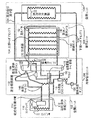
図1に高性能冷媒冷蔵冷却システムの実施形態を示す。ここに記載する実施形態では、付加的な構成要素を最小限に抑え、凝縮ユニットが蓄熱を行うために使用するエネルギー以上のエネルギーをほぼ使用しない。冷媒冷蔵システムの構成は、各種の用途に使用できるように汎用性をもって設計されている。本実施形態では、蓄積エネルギーを利用して大規模商業用途用の冷水を提供するか、あるいは複数の蒸発器に対して直接冷媒空調を行う。この構成においては複数の動作モードが採用されている。また、任意の構成要素を追加することが可能であり、最大効率でエネルギーを蓄積および放出することを可能にするスマートコントロール(smart control)を組み込むこともできる。本システムは凝縮ユニットに接続されて第1の期間で冷却エネルギーを蓄積し、第2の期間でその蓄積されたエネルギーを利用して冷却を行う。また、凝縮ユニットおよび冷媒冷蔵システムの両方を同時に動作させて第3の期間で冷却を行うこともできる。 FIG. 1 shows an embodiment of a high-performance refrigerant refrigeration cooling system. The embodiments described herein minimize additional components and use substantially no energy beyond that used by the condensing unit to store heat. The configuration of the refrigerant refrigeration system is designed with versatility so that it can be used for various applications. In this embodiment, stored energy is used to provide cold water for large-scale commercial use, or refrigerant air conditioning is performed directly on a plurality of evaporators. In this configuration, a plurality of operation modes are employed. Optional components can also be added, and smart controls can be incorporated that allow energy to be stored and released with maximum efficiency. The system is connected to the condensing unit and accumulates cooling energy in the first period, and cools using the accumulated energy in the second period. It is also possible to perform cooling in the third period by operating both the condensing unit and the refrigerant refrigeration system at the same time.
図1に示すように、冷媒を用いた高性能蓄熱冷却システムの実施形態を本システムに内蔵された4つの主要な構成要素とともに説明する。空調ユニット102は従来の凝縮ユニットであり、コンプレッサ110およびコンデンサ111を用いて高圧液体供給ライン112を介して冷却管理ユニット104へと送られる高圧液体冷媒を生成する。冷却管理ユニット104は、製氷コイル142を有し、水またはその他の共晶材料等の相変化液体が入った絶縁タンク140を含む蓄熱ユニット106に接続されている。空調ユニット102、冷却管理ユニット104および蓄熱アセンブリ106は、負荷熱交換器108(室内冷却コイルアセンブリ)に対して効率的な冷却を行うように連携して作動することにより、本システムの主要な動作モードの機能を実行する。
As shown in FIG. 1, an embodiment of a high-performance heat storage and cooling system using a refrigerant will be described together with four main components incorporated in the system. The
さらに図1に示すように、コンプレッサ110は、高圧液体供給ライン112を介して冷却管理ユニット104へと送られる高圧液体冷媒を生成する。高圧液体供給ライン112は分岐されており、油蒸留器/サージ容器116および圧力作動スライドバルブ118に供給を行う。油蒸留器/サージ容器116は低圧冷媒中の油を濃縮し、それを乾式吸引戻り管(dry suction return)114を介してコンプレッサ110に戻すために用いられる。油蒸留器/サージ容器116がないと、油が蓄積容器内に残存するので、コンプレッサ110が油不足によって最終的に停止し、熱交換器の効果が汚損によって弱められてしまう。蒸気は油蒸留器/サージ容器116上部まで上昇し、排気キャピラリ128から排出され、湿式吸引戻り管(wet suction return)124へと再導入される。これは熱交換器からの蒸気フローを油蒸留器/サージ容器116内で好ましい方向に促すために行われる。排気キャピラリ128または類似の調整抽気装置の長さを利用して油蒸留器/サージ容器116内の圧力、ひいては沸騰速度およびシステム内の冷媒量が制御される。圧力作動スライドバルブ118は、冷媒管理システム104のその他の部分を通らずに高圧液体冷媒を二次的に液体冷媒ポンプ120へ供給し、負荷ユニット108への直接供給を行う。
Further, as shown in FIG. 1, the
システムが作動すると、液体冷媒ポンプ120は、蓄熱冷却システムの負荷部108内の負荷熱交換器122の蒸発器コイルに液体冷媒を供給する。低圧冷媒は、負荷熱交換器122の蒸発器コイルから湿式吸引戻り管124を介して蓄積装置または総合冷媒管理容器(URMV)146および製氷/排氷コイル142からなる内部熱交換器に戻される。低圧蒸気はURMV146の上部から排出され、油戻しキャピラリ148を介して油蒸留器/サージ容器116の底部から流れる蒸留油を多く含む冷媒とともに、乾式吸引戻り管114を介して空調ユニット102へ戻される。油戻しキャピラリ148は、油がシステムに再導入される速度を制御する。油を多く含む液体冷媒はP−トラップ150を通過する。これにより、不要な冷媒経路が排除(ブロック)され、油蒸留器/サージ容器116が空になる。
When the system is activated, the
湿式吸引戻り管124は、URMV146に接続されるよりも先に分岐器130に接続されている。分岐器は、混合相調節器132(TRVT)からの低圧冷媒を供給する。混合相調節器132は、コンデンサ111内に十分な量の液体が蓄積されている時にのみ開口して混合相冷媒を放出するバルブ(オリフィス)を有することにより、システム内の冷媒フローを調節する。このように、本システムを駆動させるコンプレッサ110は、冷却負荷に見合った高圧冷媒を供給するために作動させるだけでよい。混合相調節器132は蒸気がシステムの低圧側(熱負荷部)に流れ込むことを防止し、蒸気が実質的にコンプレッサ110からURMV146へ供給されないようにする。その一方で、必要な圧力をコンデンサ圧力から蒸発器飽和圧力にまで降下させる。この結果、システムの全体効率が向上し、冷媒管理ユニットの液体過剰供給特性が簡素化される。
The wet suction return pipe 124 is connected to the branching device 130 before being connected to the
絶縁タンク140は、製氷/排氷兼用コイル142(表面的には幾何学的に設計されたらせんコイル)を有する。このコイルは自然循環および液体冷媒排出を行うように配置されており、上側が上部ヘッダアセンブリ154に、下側が下部ヘッダアセンブリ156に接続されている。上部ヘッダアセンブリ154は絶縁タンク140から外側に冷却管理ユニット104まで延びている。冷媒が製氷/排氷コイル142およびヘッダアセンブリ154および156を流れると、第1の期間においてコイルは蒸発器として機能し、絶縁タンク140内の流体152は固体化する。製氷/排氷コイル142ならびにヘッダアセンブリ154および156は冷媒回路の低圧側に接続され、自然循環またはポンプ循環および液体冷媒排出を行うように配置されている。第2の期間において、暖気相冷媒が製氷/排氷コイル142ならびにヘッダアセンブリ154および156を循環して氷152を融解することにより、冷媒凝縮機能が実行される。
The
一実施形態において、本システムに使用する絶縁タンク140は、ロトモールド法で成形された二重壁構造プラスチックタンクであり、タンクの蓋部、壁部および底部における絶縁値はR13からR35である。本システムは通常、蓄放熱サイクルを週単位ではなく毎日実施するので、絶縁値をさらに高くしても全体性能が有意に向上するわけではない。絶縁タンク140には、外付け冷媒管理構成要素のための接続点があり、冷媒配管の出口を形成する。タンクは水または共晶材料で充填され、流体膨張中に流体の水位を維持するための排水管を備える。
In one embodiment, the
冷媒管理ユニット104の中心となる装置は総合冷媒管理容器すなわちURMV146と呼ばれる蓄積容器である。URMV146は冷媒回路の低圧側にあっていくつかの機能を実行する。URMV146は冷媒蓄熱期間および冷却期間において液体冷媒と冷媒蒸気とを分離する。URMV146は冷媒蓄熱期間において液体冷媒を円柱状に形成し、絶縁タンク140内の製氷/排氷コイル142を通る自然循環を維持する。URMV146はまた蒸気分離容器でもあり、冷媒蓄積を行う。空調ユニット102のコンプレッサ110へ通じる乾式吸引戻り管114は、蓄熱期間においてURMV容器140上部の排出口によって形成される。乾式吸入戻り管114は、液体冷媒がコンプレッサへ戻るのを防止するように配置される。湿式吸入戻り管124は、冷媒蓄熱システムが冷却を行う間、URMV146上部の入口から蒸発器(負荷熱交換器122)に接続するように設けられる。
The central device of the refrigerant management unit 104 is a storage container called a comprehensive refrigerant management container, or
第1の期間は、冷媒蓄熱期間すなわち氷にエネルギーを蓄積する期間である。コンプレッサ110の出力は、高圧液体(HPL)に凝縮された高圧冷媒蒸気である。冷媒ポンプ120出口のバルブ(図示せず)は通電されて負荷ユニット108との接続を閉じる。高圧液体は、もう1つの冷媒容器すなわち冷媒システムの下側に接続されている油蒸留器/サージ容器兼用器116内で低圧液体冷媒に囲まれている。
The first period is a refrigerant heat storage period, that is, a period in which energy is accumulated in ice. The output of the
第1の期間(蓄熱期間)中、油蒸留器/サージ容器116は油蒸留器であり、冷却期間中は冷媒サージ容器として機能する。蓄熱期間において、空調ユニット102からの高圧液体冷媒が流れる内部熱交換器は、一部を除くほとんどの低圧液体溶媒が油蒸留器/サージ容器116に入ることを防止する。該容器内の冷媒は2つのキャピラリ管によって定められた速度で沸騰する。1つは油蒸留器/サージ容器116中の冷媒水位を制御する排気キャピラリ128である。もう1つは油を多く含む冷媒を所定の速度で空調ユニット102内のコンプレッサ110へ戻す油戻しキャピラリ148である。URMV146内において円柱状となる液体冷媒は重力の作用を受ける。油蒸留器/サージ容器116を円柱状URMV146の底部近傍に配置させることにより、油蒸留器/サージ容器116への液体冷媒供給フローが一定に維持される。この容器は蒸気がURMV146または液体冷媒ポンプ120に入るのを防ぐためのP−トラップ150を備えた低圧液体供給ライン144に接続されている。サージ機能により、冷却期間において過剰の冷媒が絶縁タンク140内の製氷/排氷コイル142から排出され、冷媒を凝縮するための表面積が最大に維持される。油蒸留器/サージ容器116の物理的配置は、蒸留器およびサージ容器としての性能を左右する一要因である。この油蒸留器/サージ容器116はさらに、コンプレッサ110に戻されるべき冷媒とともに移動する油を戻すための経路を形成する。油蒸留器/サージ容器116から排出されるわずかにサブクーリングされた(冷媒の気相−液相温度より低温)高圧液体冷媒は、圧力降下を生じさせる混合相調節器132(熱力学的冷媒蒸気トラップ)を通過する。
During the first period (heat storage period), the oil distiller /
上記のように、冷媒管理ユニット104には空調ユニットから高圧液体供給ライン112を介して高圧液体冷媒が送られる。高圧液体冷媒は油蒸留器/サージ容器116内の熱交換器を通過してサブクーリングされ、冷媒圧降下が生じる混合相調節器132へと流れる。混合相調節器132を使用することにより、液体冷媒圧力降下に加えて各種の好ましい機能がもたらされる。蓄熱期間において混合相調節器132を通過する大量の冷媒が、製氷コイル142での冷媒沸騰速度と整合する。これによって冷媒水位の制御が不要となる。混合相調節器132は、サブクーリングされた液体冷媒を通過させるが、入口で蒸気(またはサブクーリングが不十分な液体)を感知すると閉鎖する。混合相調節器132の開閉による冷媒のパルス作用は、閉鎖された円柱内に定在波を生じさせるため、液体冷媒に対してハンマー効果をもたらす。これにより、蓄熱期間において製氷コイル142内の液体冷媒が攪拌されて熱交換が向上し、液相冷媒および気相冷媒の分離が促進される。混合相調節器132はURMV146と連動して空調ユニット102から液体冷媒を排出させ、その表面積を凝縮に利用できる状態にする。混合相調節器132により、空冷式凝縮ユニットの押圧が周囲温度と共に変動可能になる。本システムにおいては、直接膨張式冷却装置に接続される大多数の凝縮ユニットにとって必須である過熱およびサブクーリング回路は不要である。
As described above, the high pressure liquid refrigerant is sent to the refrigerant management unit 104 from the air conditioning unit via the high pressure
混合相調節器132を調整することにより、冷媒蓄熱冷却システムは標準的な4段階手法(four-degree approach)で製氷を行う。混合相調節器132から排出された低圧液体冷媒は分岐器130を通過してURMV146への入口と製氷コイル142の上部ヘッダアセンブリ154との間に位置するエゼクタ(または注入ノズル)へ到達し、冷媒の自然循環を促進する。分岐器130は液体冷媒の圧力および流量を低減させる。冷媒蓄熱期間において、エゼクタは冷媒が分岐器130から排出される際に圧力降下を生じさせる。これにより、製氷コイル142内での冷媒循環速度が増し、システム性能が向上する。
By adjusting the
混合相調節器132はまた、URMV146の定圧を維持することにより蒸発器の負荷に応じて冷媒流量を変化させる。これにより、凝縮圧が周囲温度とともに変動する。周囲温度が低下すると、コンプレッサ110の押圧が低下する。混合相調節器132は液体冷媒を通過させるが、蒸気を感知するとそれを遮断する。つまり二相混合物を「トラップ」に保留する。混合相調節器は液体(濃縮されている)を通過させるが、低密度ガスが通過すると閉じられる。蒸気はコンデンサ111まで戻され、さらに凝縮されて液体になる。混合相調節器132は自動調節型(いったん較正されれば)であり、寄生損(断熱膨張)を生じない。また、混合相調節器132は蒸気を液体から取り除き、低圧側にパルス作用をもたらすことによって熱交換器のコイル内での熱交換効率を向上させる。上記のように、混合相調節器132は低圧液体を通過させるために開放され、高圧側で蒸気を閉じ込めて調節器の低圧側でパルス作用を発生させるために閉鎖される。このパルス作用は沸騰段階で分岐回路の内壁をさらに湿らせるため、熱交換が促進される。
The
低圧液体はURMV146に入り、液体成分と蒸気成分とに分離される。液体成分はURMV146を所定の水位まで満たし、蒸気成分は空調ユニット102のコンプレッサへ戻される。通常の直接膨張式冷却システムでは、蒸気成分はシステム全体を循環するため、効率が低下する。本実施形態では、蒸気成分は即座にコンプレッサ110へ戻される。URMV146内において円柱状となる液体冷媒は重力の作用を受け、蓄熱期間において2つの経路を有する。1つは油蒸留器/サージ容器116へ続く経路であって、流出速度はキャピラリ管128および148によって調整される。円柱状液体冷媒のもう1つの経路は製氷コイル142および上部ヘッダアセンブリ154を介して下部ヘッダアセンブリ156へと続き、URMV146を通過してコンプレッサ110へ戻る経路である。このような自然循環により、タンクが水等の相変化流体で充填された時にエネルギーが氷の状態で蓄積される。URMV146内の円柱状液体冷媒は、冷媒が蒸気になるにつれて製氷コイル142中で低密度になっていく。この差によって自然循環が維持される。冷媒は、まず蒸気となり、その後蓄積サイクルにおいて液体および蒸気となり、そしてURMV146に戻される。液体は再び円柱状となり、蒸気は空調ユニット102のコンプレッサ110に戻される。製氷は自然循環によって均一かつ確実に行われる。製氷コイル142のうちの1つがより多くの氷を製造すると、その熱流速度が低下する。そうすると、その隣のコイルが同等の熱流速度になるまでより多くの冷媒を受け取ることになる。
The low pressure liquid enters
製氷コイル142の構成により、製氷蓄積期間においてコンプレッサ吸引圧を高く保つための製氷パターンが作成される。蓄熱期間の最終段階において、急速製氷が行われ、吸引圧が劇的に降下する。これはフル蓄熱を意味し、調節可能な冷媒圧スイッチによって凝縮ユニットが自動的に停止される。
With the configuration of the
蓄熱期間中に空調ユニットがONされると、高圧液体冷媒の作用により、圧力作動スライドバルブのスライド(ピストン)が負荷熱交換器122への冷媒の自由流動を遮断する。蓄熱システムが十分に蓄熱され、空調ユニット102が停止すると、混合相調節器132が速やかに冷媒システムの圧力を均一化する。高圧液体がスライドを閉方向に押圧しなくなると、バネによってスライドが開位置に戻され、冷媒が無制限に負荷熱交換器122へと流れる。一実施形態において、負荷熱交換器122は蓄熱システムの下側に配置される。冷媒は重力を受けて満液式に蒸発器へと流れ、熱サイホンとして動作する。
When the air conditioning unit is turned on during the heat storage period, the slide (piston) of the pressure-actuated slide valve blocks the free flow of the refrigerant to the
要約すると、タンクが水で満たされて冷媒がコイルを循環するとき、第1の期間においてコイルは蒸発器として作用し、製氷および蓄熱を行う。第2の期間では、冷媒はコイルを循環して氷を融解し、冷媒凝縮機能を実行する。この蓄熱および放熱の原理体系は、アイス・オン・コイル、内部融解として公知である。各期間はそれぞれエンドユーザ、電力会社あるいはシステムに内蔵または付属の任意のスマートコントロールによって決定される。 In summary, when the tank is filled with water and the refrigerant circulates through the coil, the coil acts as an evaporator during the first period, making ice and storing heat. In the second period, the refrigerant circulates through the coil to melt ice and performs the refrigerant condensing function. This principle of heat storage and heat dissipation is known as ice-on-coil, internal melting. Each period is determined by an end user, a power company or any smart control built into or attached to the system.
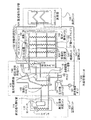
図2に複数の蒸発器(欧州および極東地域において周知のミニスプリットシステムを含む)を有する空調用に構成された高性能冷媒冷蔵冷却システムの実施形態を示す。図2に示すように、本冷媒冷蔵冷却システムには各種の効果的なオプションを追加することが可能である。先に述べたように、冷媒管理ユニット104内の液体冷媒ポンプ120は、本実施形態ではミニスプリット蒸発器160として図示される負荷に冷媒を循環させるように圧力作動スライドバルブ118の下流側に追加することができる。ミニスプリット蒸発器160の熱交換器のコイルには液体過剰供給技術によって冷媒が直接供給される。湿式吸引戻りライン124では、液体と蒸気の両方が蓄熱ユニット106へ戻される。蒸気は氷152内の放電コイル142によって凝縮され、液体冷媒は液体冷媒ポンプ120の入口へと戻される。蓄熱期間において使用可能であった過剰の冷媒は油蒸留器/サージ容器116に蓄積される。図2に圧力作動スライドバルブとともに示される冷媒経路のオプションにより、空調ユニット102および蓄熱ユニット106の両方が負荷ユニット108のミニスプリット蒸発器160のための凝縮を行うことになる。これは「Push」モードと呼ばれるもので、第3の期間において動作する。
FIG. 2 shows an embodiment of a high performance refrigerant refrigeration cooling system configured for air conditioning having a plurality of evaporators (including mini-split systems well known in Europe and the Far East). As shown in FIG. 2, various effective options can be added to the refrigerant refrigeration cooling system. As described above, the liquid
製氷/排氷コイル142を構成する複数のコイルは、製氷/排氷コイル142と物理的に接触し、氷の境界外に水を排出するための経路を形成する受動的排出管164を備えた受動的排水システムを有していてもよい。これらの受動的排出管164は、コイル間の適当な間隔を維持する支柱とともに輸送中にコイルを機械的に保護する。任意のエアーバブラー、送水ポンプ、攪拌器、循環器等を組み込んでいずれの方向のフローを促進する流体を積極的に排出することができる。流体/氷152間の排出および熱交換をさらに行うために、受動的排出フィン162を上部ヘッダアセンブリ154、下部ヘッダアセンブリ156または蓄熱ユニット106内のその他の熱交換面で用いてもよい。
The plurality of coils that make up the ice making /
前記複数のコイルはさらに、コイルと物理的に接触し、氷の境界外に水を排出するための経路を形成する管を備えた受動的排水システムを有していてもよい。これらの管は、コイル間の適当な間隔を維持する支柱とともに輸送中にコイルを機械的に保護する。任意のエアーバブラー、送水ポンプ、攪拌器、循環器等を組み込んでいずれの方向のフローを促進する流体を積極的に排出することができる。 The plurality of coils may further comprise a passive drainage system with a tube in physical contact with the coils and forming a path for draining water out of the ice boundary. These tubes mechanically protect the coils during transport along with the struts that maintain the proper spacing between the coils. Arbitrary air bubblers, water pumps, stirrers, circulators, etc. can be incorporated to positively discharge fluid that promotes flow in any direction.
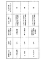
図3は3つの期間およびモードで作動する高性能冷媒冷蔵冷却システムの実施形態の構成要素の状態を示す表である。図3に示すように、3つの期間およびモードにおける空調ユニット102、油蒸留器/サージ容器116、製氷/排氷コイル142および圧力作動スライドバルブ118の状態がそれぞれ記載されている。例えば、第1の期間における冷媒冷蔵モード中、空調ユニット102はON状態であり、油蒸留器/サージ容器116は油蒸留器として作動し、製氷/排氷コイル142は下から上へ流れる冷媒を用いて製氷を行い、圧力作動スライドバルブ118は閉状態となっている。
FIG. 3 is a table showing the component states of an embodiment of a high performance refrigerant refrigeration cooling system operating in three periods and modes. As shown in FIG. 3, the states of the
この製氷(蓄熱)サイクル中、空調ユニット102はシステムに高温液体冷媒を供給する。循環路は、コンデンサ111からの高圧液体から始まって冷媒を低圧液体に変える混合相調節器132(フロート)を通過し、URMV146に流れ込む経路をたどる。本システムでは、低温液体は蓄熱ユニット106の熱交換器の下部ヘッダアセンブリ156に供給され、そこで絶縁タンク140内の水のほとんどが徐々に凍結される。気相冷媒は上部ヘッダアセンブリから排出されてURMV146へ戻る。残った液体はURMV146底部へ落下し、製氷/排氷コイル142を通って再び循環する。得られた「乾燥」低圧蒸気はURMV146から排出され、サイクルが再開する。
During this ice making (heat storage) cycle, the
第2の期間における冷却モード中、つまり冷却または氷融解(放熱)サイクルでは、空調ユニット102がOFF状態であり、油蒸留器/サージ容器116はサージ容器として作動し、製氷/排氷コイル142は上から下へ流れる冷媒を用いて凝縮を行い、冷媒ポンプ120および圧力作動スライドバルブ118は開状態となっている。
During the cooling mode in the second period, that is, in the cooling or ice melting (heat dissipation) cycle, the
ピークエネルギー時、システムに接続された空調ユニット102はOFFされ、システムは製氷サイクルで製造された氷を排出する。システムは氷によるエネルギーシンクを放出して冷却を行う。開示された実施形態においては、システムモジュールによる2つの冷却サイクル方法すなわち負荷シフトと負荷平準化がある。負荷シフトでは単一冷却回路、つまり通常の蒸発器コイルに接続されて顕熱冷却および潜熱冷却の両方を行うシステムを用いる。負荷平準化モードでは、2つの別々の冷却回路、つまり顕熱冷却(循環空気から熱を除去)を行うための顕熱蒸発器回路と、潜熱冷却(湿度除去)を行うための別の氷蒸発器とを用いて冷却を行う。通常の空調ユニット102および大型の蒸発器コイル(負荷ユニット108)が顕熱蒸発器回路を構成し、第2の蒸発器コイルおよび蓄熱ユニット106が氷蒸発器回路を構成する。負荷平準化システムのその他の実施形態においてこれらを逆にすることも可能である。
At peak energy, the
負荷シフトモードにおける冷却回路および負荷平準化モードにおける氷蒸発器回路は、どちらも蒸発器コイル(負荷ユニット108)に接続されているという点で基本的に類似している。両者の違いは負荷シフトモードにおいて負荷ユニット108が顕熱冷却および潜熱冷却の両方を行うのに対し、負荷平準化モードでは負荷ユニット108が主に潜熱冷却を行うことである。このことにより、多様な構成において異なる機能を同一基本構造のコイルによって実行することができる。
The cooling circuit in the load shift mode and the ice evaporator circuit in the load leveling mode are basically similar in that both are connected to the evaporator coil (load unit 108). The difference between the two is that the
氷融解サイクルにおいて、冷媒ポンプ120は負荷ユニット108に冷媒を送るための駆動力となる。標準的な空調システムと比較して、このシステムの特異な点とは、屋内ユニット(エアハンドラーおよび負荷ユニット108)と蓄熱ユニット106との間に150フィートもの距離があってもよいことである(通常は最大80フィート)。これは、油蒸留器/サージ容器116が液体受容器として機能し、長いラインを横断するのに必要な追加の液体冷媒量を調節するからである。標準的な空調システムでは、そのような距離があると液体不足が起こり、性能が低下する。このことにより、開示されたシステムを通常のスプリット空調装置と比べてはるかに大きな建物に適用することが可能となる。
In the ice melting cycle, the
この類の冷却装置の主な用途としては、日中時の空調によるピーク電力需要の負荷シフトが挙げられる。夏期のピーク時における高電力需要を避けるため、主として2つの方法がある。1つは負荷制限と呼ばれる方法であって、ピーク時にコンプレッサを停止して氷等の蓄積エネルギーを用いて冷却を行う方法である。もう1つは負荷平準化と呼ばれる方法であって、小型のコンプレッサを連続的に作動させる方法である。冷却需要が低い期間に熱的エネルギーを氷として蓄積する。需要が中程度の時には、小型コンプレッサユニットがその負荷要求に対応する。要求されたエネルギーを小型コンプレッサで供給しきれない高需要時は、氷を融解してシステム容量を補充することにより、その差を埋め合わせる。空調需要の低い間の製氷期間は、ピーク需要時の3時間または10時間と比較して、12〜14時間と長くしてもよい。 The main application of this type of cooling device is the load shift of peak power demand due to air conditioning during the daytime. There are two main ways to avoid high power demand at peak summer times. One is a method called load limitation, in which the compressor is stopped at the peak and cooling is performed using stored energy such as ice. The other is a method called load leveling, in which a small compressor is operated continuously. Thermal energy is stored as ice during periods of low cooling demand. When demand is moderate, the small compressor unit meets the load requirements. During high demand when the required energy cannot be supplied by a small compressor, the difference is made up by melting the ice and replenishing the system capacity. The ice making period during low air conditioning demands may be as long as 12-14 hours compared to 3 hours or 10 hours during peak demand.
以下に負荷シフトモードおよび負荷平準化モードでの氷蒸発回路のための冷媒フローを説明する。氷融解(放熱)サイクルにおいて、蓄熱ユニット106の製氷/排氷コイルはコンデンサとして作用し、負荷ユニット108からの気相冷媒を取り込んで凝縮する。低温液体冷媒(32°F〜58°F)は液体冷媒ポンプ120を介して負荷ユニット108へ循環する。負荷ユニット108が冷却管理ユニット106の下側であって十分に近いところにある場合には、このサイクルは完全な密度差をもって(熱サイホンとして)作動する。したがって、この場合には液体冷媒ポンプ120は不要となり、エネルギー消費が削減できる(システム効率が向上する)。この回路は低圧液体冷媒および気相冷媒のみを使用する。
The refrigerant flow for the ice evaporation circuit in the load shift mode and the load leveling mode will be described below. In the ice melting (heat radiation) cycle, the ice making / ice discharging coil of the
氷蒸発回路での工程は、
1.URMV146から液体冷媒をポンプで排出させ、液体冷媒ポンプ120を介して負荷ユニット108へ導く。
2.液体冷媒を負荷ユニット108で沸騰、蒸発させる。
3.気体と液体の混合物を負荷ユニット108から湿式吸引戻り管124を介してURMV146へ戻す。
4.液体冷媒がURMV146底部に落下する。
5.気相冷媒のほとんどはURMV146に入らず、冷却サブユニット(コイル)内の凝縮冷媒の吸引圧によって蓄熱ユニット106の熱交換器に入る。
6.気相冷媒は製氷/排氷コイル142に入り、下部ヘッダアセンブリ156で液体に凝縮される。
7.液体冷媒は下部ヘッダアセンブリ156から排出されてURMV146底部に回収される。
8.サイクルが繰り返される。
The process in the ice evaporation circuit is
1. The liquid refrigerant is discharged from the
2. The liquid refrigerant is boiled and evaporated by the
3. The mixture of gas and liquid is returned from the
4). Liquid refrigerant falls to the bottom of the
5. Most of the gas phase refrigerant does not enter the
6). The gas phase refrigerant enters the ice making /
7). The liquid refrigerant is discharged from the
8). The cycle is repeated.
負荷シフトモードでは、熱エネルギーユニット106のみが上記ピーク時においてエネルギーを使用する冷却システムとなる。したがって、エネルギー利用(最大100%)の大部分をその他のオフピーク時にシフトすることができる。負荷シフト機能の目的は、電力需要をオフピーク時にシフトすることである。空調ユニットが低周囲温度で稼動し、電力需要がピーク時からオフピーク時にシフトされるため、全体的な需要が低減され、効率が向上する。
In the load shift mode, only the
負荷平準化モードでは、2つの別々の冷却回路を使用して冷却を行う。第1の回路はその他の冷却システムから供給されて顕熱冷却を行うことが好ましい。ここに開示される実施形態は第2の冷却回路である氷蒸発器回路の一部として使用される。開示されるシステムは、極めて効果的な潜熱冷却を行う。なぜならこれは最も標準的な空調システムと比較してはるかに低温(低圧)の冷媒を負荷ユニット108へ供給するからである。結果として得られる露点が低いため、空気中により多くの水分(潜熱エネルギー)が与えられる。負荷平準化モードでこのシステムを使用して潜熱冷却を行うことにより、顕熱冷却専用の空調システムのサイズを小さくすることができる。小型の空気処理システムを使用することも可能である。理想的なのは、第1コイルでの除湿(潜熱冷却)を排除し、第2コイルだけでそれを行うことである。第1冷却回路の効率を向上させ、本システムを利用して第2回路に冷却を供給することにより、ピーク需要が低減し、冷却需要に応じて全体効率が向上する(従来の単一空調システムに比較して)。
In load leveling mode, cooling is performed using two separate cooling circuits. The first circuit is preferably supplied from another cooling system for sensible heat cooling. The embodiment disclosed herein is used as part of an ice evaporator circuit that is a second cooling circuit. The disclosed system provides very effective latent heat cooling. This is because a much lower temperature (low pressure) refrigerant is supplied to the
負荷平準化構造において、本システムは、冷却負荷が最小であるかまたはエネルギー管理システムによって設定されるピークの前後または冬期においても、ピーク電力需要をさらに小さくするように全冷却負荷を供給することができる。 In a load leveling structure, the system can supply a total cooling load to further reduce peak power demand even before or after the peak when the cooling load is minimal or set by the energy management system. it can.
最後に、期間3の「Push」モードでは、空調ユニット102はON状態であり、油蒸留器/サージ容器116は一体型油蒸留器・サージ容器として作動し、製氷/排氷コイル142は上から下へ流れる冷媒を用いて凝縮を行い、冷媒ポンプ120および圧力作動スライドバルブ118は開状態である。「Push」モードでは、(製氷のための)システムに付随するコンプレッサ110が負荷ユニット108に対して直接冷却(製氷)を行う。これにより、氷を使い切った後に冷却を行う、ピーク時に(氷に加えて)さらに容量を追加する、いっそうのコスト削減のために後に氷を残しておくといったさまざまの効果がもたらされる。
Finally, in the “Push” mode of period 3, the
製氷のタイミングは、例えばkWhあたりの価格といったエネルギーコストだけに対応するために計算される。しかしながら、この計算によって、全エネルギーコストに間接的に影響を及ぼす夜間の各時間帯におけるシステム効率に対応することもまた可能である。夜間の効率は周囲温度および天候条件によって異なる。夜間の温度は通常は統計データ(profile)(日の出直前が最も低い)に従うので、これを用いて製氷時間を最適化することができる。しかしながら、天気予報およびその他のフィードフォワード機構を用いて製氷時間を最適化することも可能である。製氷時間の最適化においてはノイズ、利便性、最大消費閾値等の各種制約および要因が考慮される。 The timing of ice making is calculated to accommodate only energy costs such as price per kWh. However, with this calculation it is also possible to accommodate the system efficiency in each nighttime period that indirectly affects the total energy cost. Nighttime efficiency depends on ambient temperature and weather conditions. Nighttime temperatures usually follow a profile (lowest just before sunrise), which can be used to optimize ice making time. However, it is also possible to optimize ice making time using weather forecasts and other feedforward mechanisms. In the optimization of ice making time, various restrictions and factors such as noise, convenience, and maximum consumption threshold are considered.
製氷は、予測される冷却需要に応じて最適化することもできる。つまり、計算または基準によって(次のサイクルまたはある一定の期間は)製氷の必要がないとされた時に製氷を行わないことは経済的に有益である。本システムは施設の冷却のためだけに構成される必要はなく、人間の快適性のために構成されていてもよい。本システムはどのような目的のためにも冷却を行うことができ、プロセス中の別の液体を冷却することもできる。得られる容量(速度)は、蒸発器または負荷ユニット108をバイパスして(例えば液体冷媒ポンプから)システムに出力の一部を直接供給するバルブを介して調節することができる。 Ice making can also be optimized according to anticipated cooling demands. That is, it is economically beneficial not to make ice when calculations or criteria (for the next cycle or period of time) indicate that ice making is not necessary. The system need not be configured solely for facility cooling, but may be configured for human comfort. The system can cool for any purpose and can cool another liquid in the process. The resulting volume (speed) can be adjusted via a valve that bypasses the evaporator or load unit 108 (eg, from a liquid refrigerant pump) and supplies a portion of the output directly to the system.
本システムは凝縮によって十分な量の水を生じさせるので、蒸発のために絶縁タンク140に補充を行う必要がない。凝縮によって生じた過剰の水は氷上方から地面へ続くチューブを介して排出される。この経路がタンクへの高温空気フロー源となるのを防止するために水トラップまたはその他のバルブシステムをチューブに配してもよい。
Since this system produces a sufficient amount of water by condensation, there is no need to refill the insulating
絶縁タンク140内に形成された氷塊152は、(冷媒蒸発により)上から下へかつ各製氷/排氷コイル142が設けられている内側部分から外側部分へ融解されるようになっている(コイルに接触している氷が先に融解される)。製氷/排氷コイル142に接触している氷がすべて融解すると、氷ではなく水がコイルに接触することになるが、このコイル周辺の水の「層」は上部または下部でその流出を阻止してもよい。この水層はコイルから氷への伝熱率を低下させるが、効率および作動条件は水を層状に循環させることによって向上する。このフローを作用させるためには、2つの事柄を満たす必要がある。すなわち、各製氷/排氷コイル142をたどる未凍領域(open water)から未凍領域までの完全な経路を形成することと、フローを促すための手段を設けることである。この経路を形成するには、受動的排出管164(銅管等の熱導体)をコイルアセンブリの上下方向に並ぶように配置し、長手方向において各製氷/排氷コイル142に物理的に結合させる。受動的排出管164は製氷領域を通って未凍領域へと延出している。このような導体は複数追加してもよい。各導体はそれぞれ未凍領域から始まって各コイルの水層に結合する水の「層」を形成することにより、完全な経路を形成する。各コイル上部に受動的排出管164をさらに追加し、氷の最上部を通過する別の水層を形成する。この導体は異なる構成のものであってもよく、ヘッダから上方へ延びる4本の軸であってもよいし、各コイルアセンブリの全長にわたって設けられる薄型導体フィンであってもよい。この方法は、水面がタンク内側にあって、この水が完全に氷になった時に氷の上方に未凍領域が生じるように最適化される(氷の方が低密度なので水位は製氷時に実質的に上昇する。よって水位は最初からコイルアセンブリの上方にある必要はない)。水の経路を未凍領域から各コイル、さらに氷塊上部へ続くように設けたため、水流促進の問題は解消される。受動的および能動的な方法の両方が利用可能である。受動的な方法では温度および密度の成層化によって自然流を形成できる。能動的システムでは水泡をタンクまたは各コイルに導入するか、ポンプで送水して循環させることによってフローを促進することができる。
The
図4にソレノイドバルブ166を用いた冷蔵冷却システムとしての冷却装置の別の実施形態を示す。ソレノイドバルブ166は図1の圧力作動スライドバルブ118の代替として構成されるものであって、氷融解サイクル中に開放され、製氷サイクル中に閉鎖される。圧力作動スライドバルブを使用する際は、製氷サイクルにおいて、コンプレッサから放出される高圧液体供給ライン112の圧力が高く、圧力作動スライドバルブのバネの力を上回ってしまう。そうすると、バルブのピストンが液体冷媒ポンプ120への入口ラインを閉鎖する最遠位置に移動し、液体フローを妨げる。氷融解サイクルにおいては、高圧液体供給ライン112の圧力は低いので、ピストンは直近位置に位置している。この状況で、バルブ入口と出口の両方が開放され、冷媒は液体供給ポンプ120へ流れ込み、さらに図1に示すように負荷ユニット108へと流れる。
FIG. 4 shows another embodiment of a cooling device as a refrigeration cooling system using a
圧力作動スライドバルブ118および高圧液体供給ライン112からの直接アクセスラインを排除することにより、冷媒は常にURMV146から液体冷媒ポンプ120へと流れるようになるが、そのフローはソレノイドバルブ166(本実施形態においては液体冷媒ポンプの下流側にある)によって調節される。この構成により、既成のバルブを使用することができ、圧力スイッチに頼ってフロー調節を行うかわりに電子リレー式制御装置を用いて正確にフローを制御できる。図4に示す実施形態において、冷却装置の完全制御は、冷却管理ユニット104と連動してシステム動作を制御するために使用される冷媒管理制御装置168で行ってもよい。冷媒管理制御装置168はアナログ、デジタルおよびリレー入力および出力を用いたプログラマブル論理制御装置(PLC)またはプログラマブルマイクロコントローラとして内蔵されたPC型ボードやICチップで駆動させてもよい。これによって、システムの汎用性が大幅に向上し、製造コストが低減する。また、その他の多様な用途および装置の「スマートコントロール」が可能になる。
By eliminating the direct access line from the pressure activated
冷媒管理制御装置168は、環境センサ172との通信によってリアルタイムデータおよび環境情報を受け取る。これらの環境センサ172は時間、温度、湿度(露点)、電力消費、電力コスト、エネルギー回路状態等の変数または冷却装置がいつどのように動作すべきかを決定するのに有用と思われるその他各種の変数を計測する。これらの要因により、性能を最適化させると思われる製氷サイクルの時間、速度および特定の動作またはユニットからのノイズがいつ問題となるかといったその他の要因が変更される。冷媒管理制御装置168はまた、履歴および環境データならびに性能が蓄積されるデータ回収ユニット170を有していてもよい。このデータは、ユニットの履歴データに基づいて性能を変更するために外部の人間または冷媒管理制御装置168によって利用されてもよい。冷媒管理制御装置168との通信のために、電気通信180すなわちネットワーク/インターネットへのワイヤレスリンク176またはハードワイヤリンクを容易にする通信機器174を用いてもよい。このように、回収された履歴データをシステムからダウンロードするか、または例えば天気のデータおよび予報、太陽表等の特定の制御機能をデバイスにプログラムしてもよい。例えば部分的エネルギー供給、コストまたは消費データ等の、制御装置168の直接感知能力の範囲外である最新の一般状況または予測される状況に基づき、外部制御による入力またはデータを冷媒管理制御装置168に伝達してもよい。履歴データ(制御装置が取り込んだものまたは外部からのもの)、環境データ、過去および現在の予測、天候、エネルギー、コスト、あるいは効率または所望の性能および製氷/融解時間の最適化に対して顕著な影響を与えるその他のデータを用いて、多くの用途条件における装置の性能を最適化することができる。
The refrigerant
開示されたこれらの実施形態において、熱負荷の様々な応用形態を前記実施形態と併用して適用することができる。実質的に冷媒配管を介して伝達される冷却要求をこれらのシステムを用いて利用することができる。この類のシステムは、例えば日常的な冷房、プラスチック射出成形時の冷却、釣れたばかりの鮮魚の冷却、タービン発電での入口冷却、船舶冷却および空調、ならびに各種のプロセス冷却利用等において有益である。 In these disclosed embodiments, various application forms of heat load can be applied in combination with the previous embodiments. Cooling requirements that are substantially transmitted through the refrigerant piping can be utilized with these systems. This type of system is useful, for example, in routine cooling, cooling during plastic injection molding, cooling freshly caught fresh fish, inlet cooling in turbine power generation, ship cooling and air conditioning, and various process cooling applications.
Claims (20)
少なくとも1つの熱伝導性部材によって互いに接続された下部回収ヘッダおよび上部回収ヘッダを備えた蓄熱交換器を含み、少なくとも一部が相変化液体で充填された絶縁タンクを備えた蓄熱ユニットと、
負荷熱交換器と、
前記凝縮ユニット、前記蓄熱ユニットおよび前記負荷熱交換器に接続された冷却管理ユニットと、
前記冷却管理ユニット内の総合冷媒管理容器と、
前記総合冷媒管理容器および前記負荷熱交換器に接続されて前記負荷熱交換器への冷媒供給を調節するソレノイドバルブと、
前記コンデンサからの冷媒を受ける油蒸留器/冷媒サージ容器兼用器と、
前記油蒸留器/冷媒サージ容器兼用器からの冷媒を受ける混合相調節器とを備え、
前記総合冷媒管理容器は、
冷媒を前記凝縮ユニットへ戻す排出口連結部と、
前記負荷熱交換器、前記混合相調節器、および前記蓄熱交換器の前記上部回収ヘッダからの冷媒を受ける注入口連結部と、
前記蓄熱交換器の下部回収ヘッダへの二方向冷媒フローを形成する第1底部ポートと、
前記油蒸留器/冷媒サージ容器兼用器に接続された第2底部ポートとを含むことを特徴とする冷却装置。A condensing unit with a compressor and a condenser;
A heat storage unit comprising an insulation tank comprising a lower recovery header and an upper recovery header connected to each other by at least one thermally conductive member, at least partially filled with a phase change liquid;
A load heat exchanger;
A cooling management unit connected to the condensation unit, the heat storage unit and the load heat exchanger;
A comprehensive refrigerant management container in the cooling management unit;
A solenoid valve that is connected to the general refrigerant management container and the load heat exchanger and adjusts a refrigerant supply to the load heat exchanger;
An oil distiller / refrigerant surge container combined device for receiving refrigerant from the capacitor;
A mixed phase regulator for receiving refrigerant from the oil distiller / refrigerant surge vessel combined device,
The comprehensive refrigerant management container is
An outlet connection portion for returning the refrigerant to the condensing unit;
An inlet connection for receiving refrigerant from the upper recovery header of the load heat exchanger, the mixed phase regulator, and the heat storage exchanger;
A first bottom port forming a two-way refrigerant flow to the lower recovery header of the heat storage exchanger;
And a second bottom port connected to the oil distiller / refrigerant surge vessel combined device.
少なくとも1つの熱伝導性部材によって互いに接続された下部回収ヘッダおよび上部回収ヘッダを備えた蓄熱交換器を含み、少なくとも一部が相変化液体で充填された絶縁タンクを備えた蓄熱ユニットと、
負荷熱交換器と、
前記凝縮ユニット、前記蓄熱ユニットおよび前記負荷熱交換器に接続された冷却管理ユニットと、
前記冷却管理ユニット内の総合冷媒管理容器と、
前記総合冷媒管理容器および前記負荷熱交換器に接続されて前記負荷熱交換器への冷媒供給を調節するソレノイドバルブと、
前記冷却管理ユニットと連動して冷却装置の制御動作を調整する冷媒管理制御装置と、
前記コンデンサからの冷媒を受ける油蒸留器/冷媒サージ容器兼用器と、
前記油蒸留器/冷媒サージ容器兼用器からの冷媒を受ける混合相調節器とを備え、
前記総合冷媒管理容器は、
冷媒を前記凝縮ユニットへ戻す排出口連結部と、
前記負荷熱交換器、前記混合相調節器、および前記蓄熱交換器の前記上部回収ヘッダからの冷媒を受ける注入口連結部と、
前記蓄熱交換器の下部回収ヘッダへの二方向冷媒フローを形成する第1底部ポートと、
前記油蒸留器/冷媒サージ容器兼用器に接続された第2底部ポートとを含むことを特徴とする冷却装置。A condensing unit with a compressor and a condenser;
A heat storage unit comprising an insulation tank comprising a lower recovery header and an upper recovery header connected to each other by at least one thermally conductive member, at least partially filled with a phase change liquid;
A load heat exchanger;
A cooling management unit connected to the condensation unit, the heat storage unit and the load heat exchanger;
A comprehensive refrigerant management container in the cooling management unit;
A solenoid valve that is connected to the general refrigerant management container and the load heat exchanger and adjusts a refrigerant supply to the load heat exchanger;
A refrigerant management control device that adjusts the control operation of the cooling device in conjunction with the cooling management unit;
An oil distiller / refrigerant surge container combined device for receiving refrigerant from the capacitor;
A mixed phase regulator for receiving refrigerant from the oil distiller / refrigerant surge vessel combined device,
The comprehensive refrigerant management container is
An outlet connection portion for returning the refrigerant to the condensing unit;
An inlet connection for receiving refrigerant from the upper recovery header of the load heat exchanger, the mixed phase regulator, and the heat storage exchanger;
A first bottom port forming a two-way refrigerant flow to the lower recovery header of the heat storage exchanger;
And a second bottom port connected to the oil distiller / refrigerant surge vessel combined device.
コンプレッサおよびコンデンサを備えた凝縮ユニットと、
少なくとも1つの熱伝導性部材によって互いに接続された下部回収ヘッダおよび上部回収ヘッダを備えた蓄熱交換器を含み、少なくとも一部が相変化液体で充填された絶縁タンクを備えた蓄熱ユニットと、
負荷熱交換器と、
前記凝縮ユニット、前記蓄熱ユニットおよび前記負荷熱交換器に接続された冷却管理ユニットと、
前記冷却管理ユニット内の総合冷媒管理容器と、
前記総合冷媒管理容器および前記負荷熱交換器に接続されて前記負荷熱交換器への冷媒供給を調節するソレノイドバルブと、
前記冷却管理ユニットと連動して冷却装置の制御動作を調整する冷媒管理制御装置と、
前記コンデンサからの冷媒を受ける油蒸留器/冷媒サージ容器兼用器と、
前記油蒸留器/冷媒サージ容器兼用器からの冷媒を受ける混合相調節器とを備え、
前記総合冷媒管理容器は、
冷媒を前記凝縮ユニットへ戻す排出口連結部と、
前記負荷熱交換器、前記混合相調節器、および前記蓄熱交換器の前記上部回収ヘッダからの冷媒を受ける注入口連結部と、
前記蓄熱交換器の下部回収ヘッダへの二方向冷媒フローを形成する第1底部ポートと、
前記油蒸留器/冷媒サージ容器兼用器に接続された第2底部ポートとを含んでおり、
第1の期間において冷媒を凝縮ユニットで凝縮して第1凝縮冷媒を生成する工程と、
前記第1凝縮冷媒の少なくとも一部を少なくとも一部が相変化液体で充填されたタンク内の蒸発ユニットに供給する工程と、
前記第1の期間において前記第1凝縮冷媒を前記蒸発ユニット内で蒸発させることによって多量の前記相変化液体を前記タンク内で凍結させて氷を生成し、第1膨張冷媒を生成する工程と、
前記第1膨張冷媒の少なくとも一部を前記凝縮ユニットに戻す工程と、
第2の期間において、第2膨張冷媒を前記氷塊中の前記蒸発ユニットへ循環させて前記第2膨張冷媒を凝縮し、第2凝縮冷媒を生成する工程と、
前記第2凝縮冷媒の少なくとも一部を前記総合冷媒管理容器から負荷熱交換器へ循環させる工程と、
前記負荷熱交換器内の前記第2凝縮冷媒を膨張させて前記第2の期間中に前記冷却を行うことにより、前記第2膨張冷媒を追加生成する工程と、
外部環境データを利用する冷媒管理制御装置を用いて前記冷却装置の動作を制御する工程とを含むことを特徴とする冷却装置を用いた冷却方法。The cooling device
A condensing unit with a compressor and a condenser;
A heat storage unit comprising an insulation tank comprising a lower recovery header and an upper recovery header connected to each other by at least one thermally conductive member, at least partially filled with a phase change liquid;
A load heat exchanger;
A cooling management unit connected to the condensation unit, the heat storage unit and the load heat exchanger;
A comprehensive refrigerant management container in the cooling management unit;
A solenoid valve that is connected to the general refrigerant management container and the load heat exchanger and adjusts a refrigerant supply to the load heat exchanger;
A refrigerant management control device that adjusts the control operation of the cooling device in conjunction with the cooling management unit;
An oil distiller / refrigerant surge container combined device for receiving refrigerant from the capacitor;
A mixed phase regulator for receiving refrigerant from the oil distiller / refrigerant surge vessel combined device,
The comprehensive refrigerant management container is
An outlet connection portion for returning the refrigerant to the condensing unit;
An inlet connection for receiving refrigerant from the upper recovery header of the load heat exchanger, the mixed phase regulator, and the heat storage exchanger;
A first bottom port forming a two-way refrigerant flow to the lower recovery header of the heat storage exchanger;
A second bottom port connected to the oil distiller / refrigerant surge vessel combined device,
Producing a first condensed refrigerant by condensing the refrigerant in the first period with a condensing unit;
Supplying at least a portion of the first condensed refrigerant to an evaporation unit in a tank at least partially filled with a phase change liquid;
Generating a first expanded refrigerant by freezing a large amount of the phase change liquid in the tank by evaporating the first condensed refrigerant in the evaporation unit in the first period;
Returning at least a portion of the first expansion refrigerant to the condensing unit;
Circulating the second expansion refrigerant to the evaporation unit in the ice block in the second period to condense the second expansion refrigerant to generate a second condensed refrigerant;
Circulating at least a portion of the second condensed refrigerant from the comprehensive refrigerant management container to a load heat exchanger;
A step of additionally generating the second expanded refrigerant by expanding the second condensed refrigerant in the load heat exchanger and performing the cooling during the second period;
And a method of controlling the operation of the cooling device using a refrigerant management control device using external environment data.
前記冷媒管理制御装置との通信によって前記冷却装置とのデータ送受信を行う工程をさらに備えることを特徴とする冷却装置を用いた冷却方法。In claim 14 ,
A cooling method using a cooling device, further comprising a step of transmitting and receiving data to and from the cooling device through communication with the refrigerant management control device.
Applications Claiming Priority (3)
| Application Number | Priority Date | Filing Date | Title |
|---|---|---|---|
| US51195203P | 2003-10-15 | 2003-10-15 | |
| US60/511,952 | 2003-10-15 | ||
| PCT/US2004/034105 WO2005038366A1 (en) | 2003-10-15 | 2004-10-15 | Refrigeration apparatus |
Related Child Applications (1)
| Application Number | Title | Priority Date | Filing Date |
|---|---|---|---|
| JP2010288413A Division JP2011099671A (en) | 2003-10-15 | 2010-12-24 | Cooling device |
Publications (2)
| Publication Number | Publication Date |
|---|---|
| JP2007509302A JP2007509302A (en) | 2007-04-12 |
| JP4714151B2 true JP4714151B2 (en) | 2011-06-29 |
Family
ID=34465297
Family Applications (3)
| Application Number | Title | Priority Date | Filing Date |
|---|---|---|---|
| JP2006535353A Expired - Fee Related JP4714151B2 (en) | 2003-10-15 | 2004-10-15 | Cooling system |
| JP2010288413A Pending JP2011099671A (en) | 2003-10-15 | 2010-12-24 | Cooling device |
| JP2013183706A Pending JP2014013137A (en) | 2003-10-15 | 2013-09-05 | Refrigeration apparatus |
Family Applications After (2)
| Application Number | Title | Priority Date | Filing Date |
|---|---|---|---|
| JP2010288413A Pending JP2011099671A (en) | 2003-10-15 | 2010-12-24 | Cooling device |
| JP2013183706A Pending JP2014013137A (en) | 2003-10-15 | 2013-09-05 | Refrigeration apparatus |
Country Status (7)
| Country | Link |
|---|---|
| US (1) | US7162878B2 (en) |
| EP (1) | EP1682832B1 (en) |
| JP (3) | JP4714151B2 (en) |
| AT (1) | ATE434159T1 (en) |
| DE (1) | DE602004021621D1 (en) |
| ES (1) | ES2325540T3 (en) |
| WO (1) | WO2005038366A1 (en) |
Cited By (1)
| Publication number | Priority date | Publication date | Assignee | Title |
|---|---|---|---|---|
| JP2011027412A (en) * | 2004-04-22 | 2011-02-10 | Ice Energy Inc | Mixed-phase regulator for managing coolant in refrigerant based high efficiency energy storage and cooling system |
Families Citing this family (55)
| Publication number | Priority date | Publication date | Assignee | Title |
|---|---|---|---|---|
| US8234876B2 (en) | 2003-10-15 | 2012-08-07 | Ice Energy, Inc. | Utility managed virtual power plant utilizing aggregated thermal energy storage |
| JP5203702B2 (en) * | 2004-05-25 | 2013-06-05 | アイス エナジー ホールディングス,インコーポレイテッド | Refrigerant heat storage and cooling system with enhanced heat exchange function |
| US7152413B1 (en) * | 2005-12-08 | 2006-12-26 | Anderson R David | Thermal energy transfer unit and method |
| US7363772B2 (en) * | 2004-08-18 | 2008-04-29 | Ice Energy, Inc. | Thermal energy storage and cooling system with secondary refrigerant isolation |
| CN100575818C (en) * | 2005-06-03 | 2009-12-30 | 开利公司 | Heat pump with auxiliary water heating |
| US7406839B2 (en) * | 2005-10-05 | 2008-08-05 | American Power Conversion Corporation | Sub-cooling unit for cooling system and method |
| AU2006338367B2 (en) * | 2006-02-15 | 2010-12-16 | Lg Electronics, Inc. | Non-freezing refrigerator |
| EP1989496A4 (en) * | 2006-02-15 | 2010-06-02 | Lg Electronics Inc | Refrigerator |
| CN101443719B (en) * | 2006-04-12 | 2012-05-02 | 开利公司 | HVAC&R system controller using on-line weather forecast |
| MX2009001564A (en) * | 2006-08-10 | 2010-01-18 | Ice Energy Inc | Thermal energy storage and cooling system with isolated external melt cooling. |
| US9791203B2 (en) | 2006-12-28 | 2017-10-17 | Whirlpool Corporation | Secondary fluid infrastructure within a refrigerator and method thereof |
| CN101668998B (en) * | 2007-02-02 | 2012-10-03 | 开利公司 | Enhanced refrigerant system |
| US8181470B2 (en) * | 2008-02-15 | 2012-05-22 | Ice Energy, Inc. | Thermal energy storage and cooling system utilizing multiple refrigerant and cooling loops with a common evaporator coil |
| US20090288430A1 (en) * | 2008-05-22 | 2009-11-26 | Anderson R David | Heat pump with thermal energy transfer unit and method |
| EP2313715A1 (en) * | 2008-05-28 | 2011-04-27 | Ice Energy, Inc. | Thermal energy storage and cooling system with isolated evaporator coil |
| US8166773B2 (en) * | 2008-10-08 | 2012-05-01 | Venturedyne, Ltd. | Refrigeration capacity banking for thermal cycling |
| GB2470619A (en) | 2009-02-11 | 2010-12-01 | Artica Technologies Ltd | Phase change material compound and pack |
| US8511109B2 (en) * | 2009-07-15 | 2013-08-20 | Whirlpool Corporation | High efficiency refrigerator |
| US7980093B2 (en) * | 2009-09-25 | 2011-07-19 | Whirlpool Corporation | Combined refrigerant compressor and secondary liquid coolant pump |
| US9159108B2 (en) | 2009-10-23 | 2015-10-13 | Viridity Energy, Inc. | Facilitating revenue generation from wholesale electricity markets |
| US8892264B2 (en) | 2009-10-23 | 2014-11-18 | Viridity Energy, Inc. | Methods, apparatus and systems for managing energy assets |
| US8457802B1 (en) | 2009-10-23 | 2013-06-04 | Viridity Energy, Inc. | System and method for energy management |
| US9367825B2 (en) | 2009-10-23 | 2016-06-14 | Viridity Energy, Inc. | Facilitating revenue generation from wholesale electricity markets based on a self-tuning energy asset model |
| US9159042B2 (en) | 2009-10-23 | 2015-10-13 | Viridity Energy, Inc. | Facilitating revenue generation from data shifting by data centers |
| US20110108020A1 (en) * | 2009-11-11 | 2011-05-12 | Mcenerney Bryan William | Ballast member for reducing active volume of a vessel |
| CN101737905B (en) * | 2009-12-22 | 2012-06-13 | 佛山市中格威电子有限公司 | Energy-saving method of air conditioner and economizer for air conditioner |
| CN101818958B (en) * | 2010-02-11 | 2012-11-14 | 中机西南能源科技有限公司 | Three-group plate ice machine hot-gas deicing refrigeration system |
| EP2678612B1 (en) * | 2011-02-25 | 2018-01-10 | Carrier Corporation | Air conditioning system with ice storage |
| JP2014535253A (en) | 2011-05-26 | 2014-12-25 | アイス エナジー テクノロジーズ インコーポレーテッド | System and apparatus for improving grid efficiency using statistical power distribution control |
| JP2014520244A (en) | 2011-06-17 | 2014-08-21 | アイス エナジー テクノロジーズ インコーポレーテッド | System and method for thermal energy storage by liquid-suction heat exchange |
| CN102520294B (en) * | 2011-12-29 | 2014-05-14 | 嘉兴斯达微电子有限公司 | Power cycling system for power device |
| US20130291555A1 (en) | 2012-05-07 | 2013-11-07 | Phononic Devices, Inc. | Thermoelectric refrigeration system control scheme for high efficiency performance |
| WO2013169774A2 (en) | 2012-05-07 | 2013-11-14 | Phononic Devices, Inc. | Thermoelectric heat exchanger component including protective heat spreading lid and optimal thermal interface resistance |
| US9098876B2 (en) | 2013-05-06 | 2015-08-04 | Viridity Energy, Inc. | Facilitating revenue generation from wholesale electricity markets based on a self-tuning energy asset model |
| US9171276B2 (en) | 2013-05-06 | 2015-10-27 | Viridity Energy, Inc. | Facilitating revenue generation from wholesale electricity markets using an engineering-based model |
| US20140338389A1 (en) * | 2013-05-14 | 2014-11-20 | Carrier Corporation | Vapor compression system with thermal energy storage |
| WO2014205051A1 (en) | 2013-06-18 | 2014-12-24 | Thermo King Corporation | Hybrid temperature control system and method |
| CN105473382B (en) | 2013-06-18 | 2017-09-22 | 冷王公司 | The control method of mixed refrigeration systems |
| WO2015065998A1 (en) * | 2013-10-29 | 2015-05-07 | Arizona Board Of Regents On Behalf Of Arizona State University | Peak load shifting via thermal energy storage using a thermosyphon |
| CN103746397B (en) * | 2014-01-22 | 2016-06-01 | 广东电网公司电力科学研究院 | The correction method of thermoelectricity mixed energy storage system and system |
| US9593871B2 (en) | 2014-07-21 | 2017-03-14 | Phononic Devices, Inc. | Systems and methods for operating a thermoelectric module to increase efficiency |
| US10458683B2 (en) | 2014-07-21 | 2019-10-29 | Phononic, Inc. | Systems and methods for mitigating heat rejection limitations of a thermoelectric module |
| EP3306771B1 (en) * | 2015-06-08 | 2019-11-27 | Kyocera Corporation | Electric power conversion device, electric power management device, and electric power management method |
| US9920971B2 (en) * | 2015-09-23 | 2018-03-20 | International Business Machines Corporation | Refrigerated transport temperature regulation |
| US10619916B2 (en) * | 2016-09-29 | 2020-04-14 | Tokitae Llc | Devices for use with refrigeration devices including temperature-controlled container systems |
| US10389134B2 (en) | 2017-06-21 | 2019-08-20 | Katerra, Inc. | Electrical power distribution system and method |
| CN107576004A (en) * | 2017-10-16 | 2018-01-12 | 广东美的暖通设备有限公司 | Conditioner and its control method |
| NZ764400A (en) | 2017-11-10 | 2022-09-30 | Hussmann Corp | Subcritical co2 refrigeration system using thermal storage |
| US10790662B2 (en) | 2018-04-03 | 2020-09-29 | Katerra, Inc. | DC bus-based electrical power router utilizing multiple configurable bidirectional AC/DC converters |
| US10897138B2 (en) | 2018-04-12 | 2021-01-19 | Katerra, Inc. | Method and apparatus for dynamic electrical load sensing and line to load switching |
| US11181316B2 (en) | 2018-05-30 | 2021-11-23 | Lineage Logistics, LLC | Thermal control system |
| CN109028393A (en) * | 2018-06-20 | 2018-12-18 | 安徽南国机电科技发展有限公司 | A kind of air conditioner cold accumulation temperature control system and method |
| US10558937B1 (en) | 2019-04-22 | 2020-02-11 | Lineage Logistics Llc | Scheduled thermal control system |
| US11371756B2 (en) | 2020-02-27 | 2022-06-28 | Heatcraft Refrigeration Products Llc | Cooling system with oil return to accumulator |
| US11384969B2 (en) * | 2020-02-27 | 2022-07-12 | Heatcraft Refrigeration Products Llc | Cooling system with oil return to oil reservoir |
Citations (3)
| Publication number | Priority date | Publication date | Assignee | Title |
|---|---|---|---|---|
| JP2002295912A (en) * | 2001-03-30 | 2002-10-09 | Mitsubishi Electric Corp | Freezing cycle apparatus, and its operation method |
| JP2003130421A (en) * | 2001-10-24 | 2003-05-08 | Mitsubishi Electric Corp | Operating method of heat storage-type refrigerating cycle device |
| JP2003285634A (en) * | 2002-03-29 | 2003-10-07 | Denso Corp | Air conditioning apparatus for vehicle |
Family Cites Families (57)
| Publication number | Priority date | Publication date | Assignee | Title |
|---|---|---|---|---|
| US2512576A (en) | 1947-10-29 | 1950-06-20 | Mojonnier Bros Co Inc | Refrigerating method and apparatus |
| DE1015019B (en) | 1953-06-11 | 1957-09-05 | Ideal Standard | Cooling system for direct evaporation with storage |
| JPS5116668B1 (en) | 1970-04-16 | 1976-05-26 | ||
| US4197719A (en) * | 1976-01-29 | 1980-04-15 | Dunham-Bush, Inc. | Tri-level multi-cylinder reciprocating compressor heat pump system |
| US4073306A (en) | 1977-01-27 | 1978-02-14 | Yarway Corporation | Steam trap |
| US4294078A (en) | 1977-04-26 | 1981-10-13 | Calmac Manufacturing Corporation | Method and system for the compact storage of heat and coolness by phase change materials |
| US4403645A (en) | 1978-07-12 | 1983-09-13 | Calmac Manufacturing Corporation | Compact storage of seat and coolness by phase change materials while preventing stratification |
| US4464904A (en) * | 1983-05-19 | 1984-08-14 | Union Carbide Corporation | Process for the transfer of refrigeration |
| DE3320632A1 (en) | 1983-06-08 | 1984-12-13 | Hoechst Ag, 6230 Frankfurt | HEAT EXCHANGER |
| US4565069A (en) | 1984-11-05 | 1986-01-21 | Maccracken Calvin D | Method of cyclic air conditioning with cogeneration of ice |
| US4621505A (en) * | 1985-08-01 | 1986-11-11 | Hussmann Corporation | Flow-through surge receiver |
| US4609036A (en) | 1985-08-07 | 1986-09-02 | The Dow Chemical Company | Bulk heat or cold storage device for thermal energy storage compounds |
| US4608836A (en) | 1986-02-10 | 1986-09-02 | Calmac Manufacturing Corporation | Multi-mode off-peak storage heat pump |
| US4735064A (en) | 1986-11-17 | 1988-04-05 | Fischer Harry C | Energy storage container and system |
| US5168724A (en) * | 1987-02-06 | 1992-12-08 | Reaction Thermal Systems, Inc. | Ice building, chilled water system |
| CA1318663C (en) | 1987-05-25 | 1993-06-01 | Albert Edward Merryfull | Method of manufacturing heat exchangers |
| US4940079A (en) * | 1988-08-11 | 1990-07-10 | Phenix Heat Pump Systems, Inc. | Optimal control system for refrigeration-coupled thermal energy storage |
| US4893476A (en) | 1988-08-12 | 1990-01-16 | Phenix Heat Pump Systems, Inc. | Three function heat pump system with one way receiver |
| US4916916A (en) | 1988-11-14 | 1990-04-17 | Fischer Harry C | Energy storage apparatus and method |
| US4964279A (en) | 1989-06-07 | 1990-10-23 | Baltimore Aircoil Company | Cooling system with supplemental thermal storage |
| US5005368A (en) | 1990-02-07 | 1991-04-09 | Calmac Manufacturing Corporation | Coolness storage air conditioner appliance |
| US5161382A (en) * | 1991-05-24 | 1992-11-10 | Marin Tek, Inc. | Combined cryosorption/auto-refrigerating cascade low temperature system |
| US5211029A (en) | 1991-05-28 | 1993-05-18 | Lennox Industries Inc. | Combined multi-modal air conditioning apparatus and negative energy storage system |
| JP2570931B2 (en) * | 1991-10-31 | 1997-01-16 | ダイキン工業株式会社 | Operation control device for regenerative air conditioner |
| US5255526A (en) * | 1992-03-18 | 1993-10-26 | Fischer Harry C | Multi-mode air conditioning unit with energy storage system |
| JP2757660B2 (en) * | 1992-03-19 | 1998-05-25 | 三菱電機株式会社 | Thermal storage type air conditioner |
| US5383339A (en) | 1992-12-10 | 1995-01-24 | Baltimore Aircoil Company, Inc. | Supplemental cooling system for coupling to refrigerant-cooled apparatus |
| US5307642A (en) * | 1993-01-21 | 1994-05-03 | Lennox Industries Inc. | Refrigerant management control and method for a thermal energy storage system |
| US5423378A (en) | 1994-03-07 | 1995-06-13 | Dunham-Bush | Heat exchanger element and heat exchanger using same |
| JPH0814628A (en) | 1994-06-29 | 1996-01-19 | Sanyo Electric Co Ltd | Air conditioner |
| US5678626A (en) * | 1994-08-19 | 1997-10-21 | Lennox Industries Inc. | Air conditioning system with thermal energy storage and load leveling capacity |
| US5467812A (en) | 1994-08-19 | 1995-11-21 | Lennox Industries Inc. | Air conditioning system with thermal energy storage and load leveling capacity |
| JPH08226682A (en) * | 1995-02-17 | 1996-09-03 | Chubu Electric Power Co Inc | Ice thermal storage type cooler |
| JPH08247522A (en) * | 1995-03-13 | 1996-09-27 | N T T Facilities:Kk | Heat load forecast device |
| US5647225A (en) | 1995-06-14 | 1997-07-15 | Fischer; Harry C. | Multi-mode high efficiency air conditioning system |
| US5682752A (en) | 1995-07-11 | 1997-11-04 | Lennox Industries Inc. | Refrigerant management control and method for a thermal energy storage system |
| US5598720A (en) | 1995-08-02 | 1997-02-04 | Calmac Manufacturing Corporation | Air bubble heat transfer enhancement system coolness storage apparatus |
| US5666823A (en) * | 1996-01-31 | 1997-09-16 | Air Products And Chemicals, Inc. | High pressure combustion turbine and air separation system integration |
| US5727393A (en) * | 1996-04-12 | 1998-03-17 | Hussmann Corporation | Multi-stage cooling system for commerical refrigeration |
| US5720178A (en) | 1996-07-15 | 1998-02-24 | Calmac Manufacturing Corporation | Refrigeration system with isolation of vapor component from compressor |
| JP3852501B2 (en) * | 1997-05-12 | 2006-11-29 | 三菱電機株式会社 | Thermal storage air conditioner |
| JPH10339483A (en) * | 1997-06-06 | 1998-12-22 | Daikin Ind Ltd | Thermal storage device |
| US5860285A (en) * | 1997-06-06 | 1999-01-19 | Carrier Corporation | System for monitoring outdoor heat exchanger coil |
| DE19831127A1 (en) | 1998-07-11 | 2001-03-15 | Baelz Gmbh Helmut | Prediction-controlled air conditioning system has communications device connected to regulator for specifying demand value, accepting future weather conditions information signals |
| US6247522B1 (en) | 1998-11-04 | 2001-06-19 | Baltimore Aircoil Company, Inc. | Heat exchange members for thermal storage apparatus |
| US6158499A (en) | 1998-12-23 | 2000-12-12 | Fafco, Inc. | Method and apparatus for thermal energy storage |
| JP2000249420A (en) | 1999-03-01 | 2000-09-14 | Daikin Ind Ltd | Ice thermal storage device and ice thermal storage refrigerator |
| JP2000266368A (en) | 1999-03-16 | 2000-09-29 | Hitachi Air Conditioning System Co Ltd | Air-conditioner system |
| US6250098B1 (en) | 2000-02-08 | 2001-06-26 | Chung-Ping Huang | Support frame for an ice-storing tank for an air conditioner with an ice-storing mode |
| JP2001296068A (en) | 2000-04-14 | 2001-10-26 | Daikin Ind Ltd | Regenerative refrigerating device |
| US6318100B1 (en) * | 2000-04-14 | 2001-11-20 | Carrier Corporation | Integrated electronic refrigerant management system |
| JP4547776B2 (en) * | 2000-06-19 | 2010-09-22 | ダイキン工業株式会社 | Demand control system for electric equipment, demand control method, demand control management apparatus, and demand control management method |
| DE10057834C2 (en) | 2000-11-22 | 2002-11-28 | Ingo Brauns | Process for controlling the energy consumption of a heating and / or cooling system |
| JP2002165279A (en) * | 2000-11-27 | 2002-06-07 | Matsushita Electric Works Ltd | Comfortable environment control system for facility unit of buildings and the like |
| JP2002303458A (en) * | 2001-03-30 | 2002-10-18 | Sanyo Electric Co Ltd | Ice storage system for cooling equipment |
| US20020162342A1 (en) | 2001-05-01 | 2002-11-07 | Kuo-Liang Weng | Method for controlling air conditioner/heater by thermal storage |
| USD501490S1 (en) | 2003-12-16 | 2005-02-01 | Ice Energy, Llc | Thermal energy storage module |
-
2004
- 2004-10-15 DE DE602004021621T patent/DE602004021621D1/en active Active
- 2004-10-15 US US10/967,114 patent/US7162878B2/en active Active
- 2004-10-15 ES ES04795292T patent/ES2325540T3/en active Active
- 2004-10-15 AT AT04795292T patent/ATE434159T1/en not_active IP Right Cessation
- 2004-10-15 EP EP04795292A patent/EP1682832B1/en not_active Not-in-force
- 2004-10-15 JP JP2006535353A patent/JP4714151B2/en not_active Expired - Fee Related
- 2004-10-15 WO PCT/US2004/034105 patent/WO2005038366A1/en active Application Filing
-
2010
- 2010-12-24 JP JP2010288413A patent/JP2011099671A/en active Pending
-
2013
- 2013-09-05 JP JP2013183706A patent/JP2014013137A/en active Pending
Patent Citations (3)
| Publication number | Priority date | Publication date | Assignee | Title |
|---|---|---|---|---|
| JP2002295912A (en) * | 2001-03-30 | 2002-10-09 | Mitsubishi Electric Corp | Freezing cycle apparatus, and its operation method |
| JP2003130421A (en) * | 2001-10-24 | 2003-05-08 | Mitsubishi Electric Corp | Operating method of heat storage-type refrigerating cycle device |
| JP2003285634A (en) * | 2002-03-29 | 2003-10-07 | Denso Corp | Air conditioning apparatus for vehicle |
Cited By (1)
| Publication number | Priority date | Publication date | Assignee | Title |
|---|---|---|---|---|
| JP2011027412A (en) * | 2004-04-22 | 2011-02-10 | Ice Energy Inc | Mixed-phase regulator for managing coolant in refrigerant based high efficiency energy storage and cooling system |
Also Published As
| Publication number | Publication date |
|---|---|
| DE602004021621D1 (en) | 2009-07-30 |
| JP2007509302A (en) | 2007-04-12 |
| JP2011099671A (en) | 2011-05-19 |
| ES2325540T3 (en) | 2009-09-08 |
| US7162878B2 (en) | 2007-01-16 |
| EP1682832B1 (en) | 2009-06-17 |
| ATE434159T1 (en) | 2009-07-15 |
| WO2005038366A1 (en) | 2005-04-28 |
| EP1682832A1 (en) | 2006-07-26 |
| US20050132734A1 (en) | 2005-06-23 |
| JP2014013137A (en) | 2014-01-23 |
Similar Documents
| Publication | Publication Date | Title |
|---|---|---|
| JP4714151B2 (en) | Cooling system | |
| JP4623600B2 (en) | High performance heat storage and cooling system using refrigerant | |
| US7854129B2 (en) | Refrigeration apparatus | |
| JP5203702B2 (en) | Refrigerant heat storage and cooling system with enhanced heat exchange function | |
| US7690212B2 (en) | Mixed-phase regulator for managing coolant in a refrigerant based high efficiency energy storage and cooling system | |
| US8234876B2 (en) | Utility managed virtual power plant utilizing aggregated thermal energy storage | |
| US20100252232A1 (en) | Thermal energy module | |
| CN100547323C (en) | Have thermal energy storage and cooling system that secondary refrigerant is isolated | |
| CN104334984A (en) | Cooling system | |
| KR20180109449A (en) | Heat pump system which can supply heat and chill | |
| PL219940B1 (en) | Water heat pump and a method for optimization of the water heat pump | |
| US11015870B2 (en) | Water tank for use in an air-conditioning or heating system | |
| EP1811236A2 (en) | Refrigeration apparatus with a refrigerant management controller | |
| MXPA06004003A (en) | Refrigeration apparatus | |
| CN106766358B (en) | Solar ice source heat pump heating system | |
| MXPA06004004A (en) | High efficiency refrigerant based energy storage and cooling system |
Legal Events
| Date | Code | Title | Description |
|---|---|---|---|
| A621 | Written request for application examination |
Free format text: JAPANESE INTERMEDIATE CODE: A621 Effective date: 20070926 |
|
| A131 | Notification of reasons for refusal |
Free format text: JAPANESE INTERMEDIATE CODE: A131 Effective date: 20100316 |
|
| A521 | Request for written amendment filed |
Free format text: JAPANESE INTERMEDIATE CODE: A523 Effective date: 20100615 |
|
| A02 | Decision of refusal |
Free format text: JAPANESE INTERMEDIATE CODE: A02 Effective date: 20100824 |
|
| A521 | Request for written amendment filed |
Free format text: JAPANESE INTERMEDIATE CODE: A523 Effective date: 20101224 |
|
| A911 | Transfer to examiner for re-examination before appeal (zenchi) |
Free format text: JAPANESE INTERMEDIATE CODE: A911 Effective date: 20110106 |
|
| A01 | Written decision to grant a patent or to grant a registration (utility model) |
Free format text: JAPANESE INTERMEDIATE CODE: A01 Effective date: 20110301 |
|
| A61 | First payment of annual fees (during grant procedure) |
Free format text: JAPANESE INTERMEDIATE CODE: A61 Effective date: 20110325 |
|
| R250 | Receipt of annual fees |
Free format text: JAPANESE INTERMEDIATE CODE: R250 |
|
| LAPS | Cancellation because of no payment of annual fees |