JP4713397B2 - Microchannel structure and microdroplet generation system - Google Patents
Microchannel structure and microdroplet generation system Download PDFInfo
- Publication number
- JP4713397B2 JP4713397B2 JP2006134231A JP2006134231A JP4713397B2 JP 4713397 B2 JP4713397 B2 JP 4713397B2 JP 2006134231 A JP2006134231 A JP 2006134231A JP 2006134231 A JP2006134231 A JP 2006134231A JP 4713397 B2 JP4713397 B2 JP 4713397B2
- Authority
- JP
- Japan
- Prior art keywords
- fluid
- microchannel structure
- channel
- dispersed phase
- flow path
- Prior art date
- Legal status (The legal status is an assumption and is not a legal conclusion. Google has not performed a legal analysis and makes no representation as to the accuracy of the status listed.)
- Expired - Fee Related
Links
Images


Classifications
-
- B—PERFORMING OPERATIONS; TRANSPORTING
- B01—PHYSICAL OR CHEMICAL PROCESSES OR APPARATUS IN GENERAL
- B01J—CHEMICAL OR PHYSICAL PROCESSES, e.g. CATALYSIS OR COLLOID CHEMISTRY; THEIR RELEVANT APPARATUS
- B01J13/00—Colloid chemistry, e.g. the production of colloidal materials or their solutions, not otherwise provided for; Making microcapsules or microballoons
- B01J13/02—Making microcapsules or microballoons
- B01J13/04—Making microcapsules or microballoons by physical processes, e.g. drying, spraying
-
- B—PERFORMING OPERATIONS; TRANSPORTING
- B01—PHYSICAL OR CHEMICAL PROCESSES OR APPARATUS IN GENERAL
- B01F—MIXING, e.g. DISSOLVING, EMULSIFYING OR DISPERSING
- B01F23/00—Mixing according to the phases to be mixed, e.g. dispersing or emulsifying
- B01F23/40—Mixing liquids with liquids; Emulsifying
- B01F23/41—Emulsifying
-
- B—PERFORMING OPERATIONS; TRANSPORTING
- B01—PHYSICAL OR CHEMICAL PROCESSES OR APPARATUS IN GENERAL
- B01F—MIXING, e.g. DISSOLVING, EMULSIFYING OR DISPERSING
- B01F25/00—Flow mixers; Mixers for falling materials, e.g. solid particles
- B01F25/30—Injector mixers
- B01F25/31—Injector mixers in conduits or tubes through which the main component flows
- B01F25/313—Injector mixers in conduits or tubes through which the main component flows wherein additional components are introduced in the centre of the conduit
- B01F25/3132—Injector mixers in conduits or tubes through which the main component flows wherein additional components are introduced in the centre of the conduit by using two or more injector devices
-
- B—PERFORMING OPERATIONS; TRANSPORTING
- B01—PHYSICAL OR CHEMICAL PROCESSES OR APPARATUS IN GENERAL
- B01F—MIXING, e.g. DISSOLVING, EMULSIFYING OR DISPERSING
- B01F25/00—Flow mixers; Mixers for falling materials, e.g. solid particles
- B01F25/40—Static mixers
- B01F25/42—Static mixers in which the mixing is affected by moving the components jointly in changing directions, e.g. in tubes provided with baffles or obstructions
- B01F25/43—Mixing tubes, e.g. wherein the material is moved in a radial or partly reversed direction
- B01F25/431—Straight mixing tubes with baffles or obstructions that do not cause substantial pressure drop; Baffles therefor
- B01F25/43197—Straight mixing tubes with baffles or obstructions that do not cause substantial pressure drop; Baffles therefor characterised by the mounting of the baffles or obstructions
- B01F25/431971—Mounted on the wall
-
- B—PERFORMING OPERATIONS; TRANSPORTING
- B01—PHYSICAL OR CHEMICAL PROCESSES OR APPARATUS IN GENERAL
- B01F—MIXING, e.g. DISSOLVING, EMULSIFYING OR DISPERSING
- B01F25/00—Flow mixers; Mixers for falling materials, e.g. solid particles
- B01F25/40—Static mixers
- B01F25/42—Static mixers in which the mixing is affected by moving the components jointly in changing directions, e.g. in tubes provided with baffles or obstructions
- B01F25/43—Mixing tubes, e.g. wherein the material is moved in a radial or partly reversed direction
- B01F25/433—Mixing tubes wherein the shape of the tube influences the mixing, e.g. mixing tubes with varying cross-section or provided with inwardly extending profiles
- B01F25/4338—Mixers with a succession of converging-diverging cross-sections, i.e. undulating cross-section
-
- B—PERFORMING OPERATIONS; TRANSPORTING
- B01—PHYSICAL OR CHEMICAL PROCESSES OR APPARATUS IN GENERAL
- B01F—MIXING, e.g. DISSOLVING, EMULSIFYING OR DISPERSING
- B01F33/00—Other mixers; Mixing plants; Combinations of mixers
- B01F33/30—Micromixers
- B01F33/301—Micromixers using specific means for arranging the streams to be mixed, e.g. channel geometries or dispositions
- B01F33/3011—Micromixers using specific means for arranging the streams to be mixed, e.g. channel geometries or dispositions using a sheathing stream of a fluid surrounding a central stream of a different fluid, e.g. for reducing the cross-section of the central stream or to produce droplets from the central stream
-
- B—PERFORMING OPERATIONS; TRANSPORTING
- B01—PHYSICAL OR CHEMICAL PROCESSES OR APPARATUS IN GENERAL
- B01J—CHEMICAL OR PHYSICAL PROCESSES, e.g. CATALYSIS OR COLLOID CHEMISTRY; THEIR RELEVANT APPARATUS
- B01J13/00—Colloid chemistry, e.g. the production of colloidal materials or their solutions, not otherwise provided for; Making microcapsules or microballoons
- B01J13/02—Making microcapsules or microballoons
- B01J13/06—Making microcapsules or microballoons by phase separation
- B01J13/08—Simple coacervation, i.e. addition of highly hydrophilic material
-
- B—PERFORMING OPERATIONS; TRANSPORTING
- B01—PHYSICAL OR CHEMICAL PROCESSES OR APPARATUS IN GENERAL
- B01J—CHEMICAL OR PHYSICAL PROCESSES, e.g. CATALYSIS OR COLLOID CHEMISTRY; THEIR RELEVANT APPARATUS
- B01J19/00—Chemical, physical or physico-chemical processes in general; Their relevant apparatus
- B01J19/0093—Microreactors, e.g. miniaturised or microfabricated reactors
-
- B—PERFORMING OPERATIONS; TRANSPORTING
- B01—PHYSICAL OR CHEMICAL PROCESSES OR APPARATUS IN GENERAL
- B01F—MIXING, e.g. DISSOLVING, EMULSIFYING OR DISPERSING
- B01F25/00—Flow mixers; Mixers for falling materials, e.g. solid particles
- B01F25/40—Static mixers
- B01F25/42—Static mixers in which the mixing is affected by moving the components jointly in changing directions, e.g. in tubes provided with baffles or obstructions
- B01F25/43—Mixing tubes, e.g. wherein the material is moved in a radial or partly reversed direction
- B01F25/431—Straight mixing tubes with baffles or obstructions that do not cause substantial pressure drop; Baffles therefor
- B01F25/4317—Profiled elements, e.g. profiled blades, bars, pillars, columns or chevrons
-
- B—PERFORMING OPERATIONS; TRANSPORTING
- B01—PHYSICAL OR CHEMICAL PROCESSES OR APPARATUS IN GENERAL
- B01J—CHEMICAL OR PHYSICAL PROCESSES, e.g. CATALYSIS OR COLLOID CHEMISTRY; THEIR RELEVANT APPARATUS
- B01J2219/00—Chemical, physical or physico-chemical processes in general; Their relevant apparatus
- B01J2219/00781—Aspects relating to microreactors
- B01J2219/00783—Laminate assemblies, i.e. the reactor comprising a stack of plates
-
- B—PERFORMING OPERATIONS; TRANSPORTING
- B01—PHYSICAL OR CHEMICAL PROCESSES OR APPARATUS IN GENERAL
- B01J—CHEMICAL OR PHYSICAL PROCESSES, e.g. CATALYSIS OR COLLOID CHEMISTRY; THEIR RELEVANT APPARATUS
- B01J2219/00—Chemical, physical or physico-chemical processes in general; Their relevant apparatus
- B01J2219/00781—Aspects relating to microreactors
- B01J2219/00819—Materials of construction
- B01J2219/00831—Glass
-
- B—PERFORMING OPERATIONS; TRANSPORTING
- B01—PHYSICAL OR CHEMICAL PROCESSES OR APPARATUS IN GENERAL
- B01J—CHEMICAL OR PHYSICAL PROCESSES, e.g. CATALYSIS OR COLLOID CHEMISTRY; THEIR RELEVANT APPARATUS
- B01J2219/00—Chemical, physical or physico-chemical processes in general; Their relevant apparatus
- B01J2219/00781—Aspects relating to microreactors
- B01J2219/00851—Additional features
- B01J2219/00858—Aspects relating to the size of the reactor
- B01J2219/0086—Dimensions of the flow channels
-
- B—PERFORMING OPERATIONS; TRANSPORTING
- B01—PHYSICAL OR CHEMICAL PROCESSES OR APPARATUS IN GENERAL
- B01J—CHEMICAL OR PHYSICAL PROCESSES, e.g. CATALYSIS OR COLLOID CHEMISTRY; THEIR RELEVANT APPARATUS
- B01J2219/00—Chemical, physical or physico-chemical processes in general; Their relevant apparatus
- B01J2219/00781—Aspects relating to microreactors
- B01J2219/00851—Additional features
- B01J2219/00869—Microreactors placed in parallel, on the same or on different supports
-
- B—PERFORMING OPERATIONS; TRANSPORTING
- B01—PHYSICAL OR CHEMICAL PROCESSES OR APPARATUS IN GENERAL
- B01J—CHEMICAL OR PHYSICAL PROCESSES, e.g. CATALYSIS OR COLLOID CHEMISTRY; THEIR RELEVANT APPARATUS
- B01J2219/00—Chemical, physical or physico-chemical processes in general; Their relevant apparatus
- B01J2219/00781—Aspects relating to microreactors
- B01J2219/00889—Mixing
-
- B—PERFORMING OPERATIONS; TRANSPORTING
- B01—PHYSICAL OR CHEMICAL PROCESSES OR APPARATUS IN GENERAL
- B01J—CHEMICAL OR PHYSICAL PROCESSES, e.g. CATALYSIS OR COLLOID CHEMISTRY; THEIR RELEVANT APPARATUS
- B01J2219/00—Chemical, physical or physico-chemical processes in general; Their relevant apparatus
- B01J2219/00781—Aspects relating to microreactors
- B01J2219/00891—Feeding or evacuation
-
- B—PERFORMING OPERATIONS; TRANSPORTING
- B01—PHYSICAL OR CHEMICAL PROCESSES OR APPARATUS IN GENERAL
- B01L—CHEMICAL OR PHYSICAL LABORATORY APPARATUS FOR GENERAL USE
- B01L2200/00—Solutions for specific problems relating to chemical or physical laboratory apparatus
- B01L2200/06—Fluid handling related problems
- B01L2200/0636—Focussing flows, e.g. to laminate flows
-
- B—PERFORMING OPERATIONS; TRANSPORTING
- B01—PHYSICAL OR CHEMICAL PROCESSES OR APPARATUS IN GENERAL
- B01L—CHEMICAL OR PHYSICAL LABORATORY APPARATUS FOR GENERAL USE
- B01L3/00—Containers or dishes for laboratory use, e.g. laboratory glassware; Droppers
- B01L3/50—Containers for the purpose of retaining a material to be analysed, e.g. test tubes
- B01L3/502—Containers for the purpose of retaining a material to be analysed, e.g. test tubes with fluid transport, e.g. in multi-compartment structures
- B01L3/5027—Containers for the purpose of retaining a material to be analysed, e.g. test tubes with fluid transport, e.g. in multi-compartment structures by integrated microfluidic structures, i.e. dimensions of channels and chambers are such that surface tension forces are important, e.g. lab-on-a-chip
Landscapes
- Chemical & Material Sciences (AREA)
- Chemical Kinetics & Catalysis (AREA)
- Dispersion Chemistry (AREA)
- Organic Chemistry (AREA)
- Physical Or Chemical Processes And Apparatus (AREA)
- Micromachines (AREA)
- Manufacturing Of Micro-Capsules (AREA)
Description
本発明は、一般的にマイクロリアクタ、マイクロ化学プロセスと総称される、数マイクロメートルから数ミリメートルの流路構造体を用いて流体を操作し、化学工学単位操作又は分析を短時間に安定的に実現する技術に関し、具体的には、微小流路構造体及び微小液滴生成システムに関する。
本発明は、画像表示素子(重合トナー、電気泳動型ペーパーライクディスプレイ用途のマイクロカプセル)、ドラッグデリバリー用途のエマルション、塗料、化粧品、その他エマルション、感光材料などに利用される微粒子や微粒子分散体及びその製造方法に応用することができる。
The present invention operates a fluid using a flow channel structure of several micrometers to several millimeters, generally called a microreactor or a microchemical process, and stably realizes a chemical engineering unit operation or analysis in a short time. relates to technology, specifically, it relates to a fine channel and fine droplets produced system.
The present invention relates to fine particles and fine particle dispersions used in image display elements (polymerized toner, microcapsules for electrophoretic paper-like display), emulsions for drug delivery, paints, cosmetics, other emulsions, photosensitive materials, and the like, and their It can be applied to a manufacturing method.
エマルション及びエマルションにおける分散相を固化して得られる微粒子又は液滴表面を固化して得られるカプセル微粒子は産業上様々な用途に用いられている。
現在、乳化分散体の工業的生産には以下の手法が用いられている。
(1)ホモジナイザーによる乳化(特許文献1等)
(2)超音波乳化(特許文献2等)
これらの技術は、連続相に、分散相として、微粒子化して分散させたい物質を投入し、機械的作用を与えることでせん断力を繰り返し与え、乳化分散体を得るのであるが、分散相に与えられるせん断力が、乳化位置によって不均一であるために、多分散な微粒子が生成する。
これに対し、
(3)多孔質ガラス膜を用いた乳化(特許文献3等)は、分散相と連続相を多孔質ガラス膜により仕切り、分散相を連続相側へ押し出すことにより分散相が膜を通過し、連続相に接触し表面張力がせん断力となり最終的に分散相が微粒子化し、乳化分散体を得る方法である。
ところが、生成される微粒子の粒子径は孔径の不均一さに依存し、多分散な微粒子が生成する。
Emulsions and fine particles obtained by solidifying the dispersed phase in the emulsion or capsule fine particles obtained by solidifying the droplet surface are used in various industrial applications.
Currently, the following methods are used for industrial production of emulsified dispersions.
(1) Emulsification using a homogenizer (
(2) Ultrasonic emulsification (
In these technologies, a substance to be dispersed in the form of fine particles as a dispersed phase is added to the continuous phase, and a shearing force is repeatedly applied by applying a mechanical action to obtain an emulsified dispersion. Since the shearing force to be applied is not uniform depending on the emulsification position, polydispersed fine particles are generated.
In contrast,
(3) Emulsification using a porous glass membrane (
However, the particle size of the generated fine particles depends on the nonuniformity of the pore size, and polydispersed fine particles are generated.
高度な単分散性を有する乳化分散体や微粒子を製造する方法としては、
(4)マイクロチャネル乳化(特許文献4等)が挙げられる。分散相と連続相を区切る膜を人工的に一様な構造とし、(微粒子の直径の標準偏差/微粒子の平均直径)が0.03以下の非常に単分散性の高い微粒子が得られるが、所望の大きさの粒子に対して各チャネルの大きさが小さいために含微粒子液体を分散相に用いた場合目詰まりの問題があると考えられる。
(5)特許文献5には、Y字型のマイクロチャネルを複数用い、単分散マイクロ液滴の生成を行う方法が開示されている。しかし、多数の流路を形成し、同じ流量の流体を全てに導入することは困難である。また、1チャネルから単位時間あたりに発生する液滴の数は数千個程度であり、収量性が低い。
特許文献6には、膜乳化法によるトナーの製造方法が開示されている。
As a method for producing an emulsified dispersion and fine particles having a high degree of monodispersity,
(4) Microchannel emulsification (Patent Document 4 etc.) Although the membrane that separates the dispersed phase and the continuous phase has an artificially uniform structure, (monodisperse of the fine particle diameter / average diameter of the fine particle) of 0.03 or less can be obtained. It is considered that there is a problem of clogging when the fine particle liquid is used in the dispersed phase because the size of each channel is small with respect to particles of a desired size.
(5)
Patent Document 6 discloses a toner production method using a film emulsification method.
本発明は、簡単な構成のマイクロチャネルを用いた方式において、単分散性の高い微小液滴を生成できるとともに、生産量を大幅に向上できる微小流路構造体の提供を、その主な目的とする。 The main object of the present invention is to provide a microchannel structure that can generate microdroplets with high monodispersity and can greatly improve the production volume in a system using a microchannel with a simple configuration. To do.
上記目的を達成するために、請求項1記載の発明では、微小液滴を生成する微小流路構造体において、液滴化される分散相の流体と、該分散相の流体とは相溶性が無く液滴を分散させる媒体としての連続相の流体とをそれぞれ個別に導入する流体導入流路と、これらの流体が合流する合流流路と、該合流流路からの流体の排出を可能とする共通出口部とを有し、前記合流流路には、流体間の界面に擾乱を誘起し、前記分散相の流体を液滴化するために、流路断面積が流体進行方向に周期的に変化する凹凸の周期構造を有する領域が存在し、前記領域には、凹凸の繰り返し回数が10回以上となるように、凸構造又は凹構造が流体進行方向に等間隔に複数形成され、前記流体導入流路における前記分散相の流体を導入する流路の出口形状が、前記流体導入流路における複数の流路の配置方向を幅方向、該幅方向に対し垂直な方向を深さ方向とした場合、「深さ方向長さ/幅方向長さ」の値が1より大きい断面形状を有することを特徴とする。 In order to achieve the above object, according to the first aspect of the present invention, in the microchannel structure for generating microdroplets, the dispersed phase fluid to be formed into droplets and the dispersed phase fluid have compatibility. And a fluid introduction channel for individually introducing continuous phase fluids as a medium for dispersing droplets, a merging channel where these fluids merge, and a fluid discharge from the merging channel A cross-sectional area of the flow path periodically in the fluid traveling direction in order to induce a disturbance at the interface between the fluids and dropletize the fluid in the dispersed phase. There is a region having a periodic structure of irregularities that changes, and in the region, a plurality of convex structures or concave structures are formed at equal intervals in the fluid traveling direction so that the number of repetitions of irregularities is 10 or more. The outlet shape of the flow channel for introducing the dispersed phase fluid in the introduction flow channel is When the arrangement direction of the plurality of flow paths in the fluid introduction flow path is the width direction and the direction perpendicular to the width direction is the depth direction, the value of “depth direction length / width direction length” is greater than 1. It has a cross-sectional shape.
請求項2に記載の発明では、請求項1に記載の微小流路構造体において、前記合流流路の流路断面積が流体進行方向に周期的に変化する領域は、前記深さ方向あるいは前記幅方向のいずれかひとつの方向の長さが異なるものであることを特徴とする。
請求項3に記載の発明では、請求項1又は2に記載の微小流路構造体において、前記流体導入流路が、流体の進行方向と直交する方向に流体の種類毎に交互に複数並列配置されていることを特徴とする。
請求項4に記載の発明では、請求項3に記載の微小流路構造体において、前記合流流路の壁面に接する端部の流体は連続相であることを特徴とする。
請求項5に記載の発明では、請求項1乃至4のうちのいずれか1つに記載の微小流路構造体において、前記凹凸の周期構造が、矩形波もしくは矩形波状の形状を有していることを特徴とする。
請求項6に記載の発明では、請求項1乃至4のうちのいずれか1つに記載の微小流路構造体において、前記凹凸の周期構造が、異なる矩形波もしくは矩形波状の形状を組み合わせた形状を有していることを特徴とする。
According to a second aspect of the present invention, in the microchannel structure according to the first aspect, the region where the cross-sectional area of the merging channel periodically changes in the fluid traveling direction is the depth direction or the The length in any one direction of the width direction is different .
According to a third aspect of the present invention, in the microchannel structure according to the first or second aspect, a plurality of the fluid introduction channels are alternately arranged in parallel for each type of fluid in a direction perpendicular to the fluid traveling direction. It is characterized by being.
According to a fourth aspect of the present invention, in the microchannel structure according to the third aspect , the fluid at the end in contact with the wall surface of the merged channel is a continuous phase .
According to a fifth aspect of the present invention, in the microchannel structure according to any one of the first to fourth aspects, the irregular structure has a rectangular wave shape or a rectangular wave shape. It is characterized by that.
In the invention according to claim 6, in the microchannel structure according to any one of
請求項7に記載の発明では、請求項1乃至4のうちのいずれか1つに記載の微小流路構造体において、前記合流流路の壁面の硬度が流体の進行方向に間隔をおいて異なり、硬度の低い部分が流体の圧力で凹むことにより前記凹凸の周期構造が発現することを特徴とする。
請求項8に記載の発明では、請求項1乃至7のうちのいずれか1つに記載の微小流路構造体において、前記領域の周期波長が、液滴化される流体の合流直前における円相当直径の3.0〜10.0倍であることを特徴とする。
請求項9に記載の発明では、微小液滴生成システムにおいて、請求項1乃至8のうちのいずれか1つに記載の微小流路構造体を有することを特徴とする。
請求項10に記載の発明では、請求項9に記載の微小液滴生成システムにおいて、前記微小流路構造体により生成された液滴の表面に膜を形成するための手段を有していることを特徴とする。
According to a seventh aspect of the present invention, in the microchannel structure according to any one of the first to fourth aspects, the hardness of the wall surface of the merging channel differs at intervals in the fluid traveling direction. The concave and convex periodic structure is manifested when the low hardness portion is recessed by fluid pressure.
According to an eighth aspect of the present invention, in the microchannel structure according to any one of the first to seventh aspects, the periodic wavelength of the region corresponds to a circle immediately before the fluid to be dropletized is merged The diameter is 3.0 to 10.0 times the diameter.
According to a ninth aspect of the present invention, the microdroplet generation system includes the microchannel structure according to any one of the first to eighth aspects.
According to a tenth aspect of the present invention, in the microdroplet generation system according to the ninth aspect, the microdroplet generation system has means for forming a film on the surface of the droplet generated by the microchannel structure. It is characterized by .
本発明によれば、流体の通過する断面積を変化させ、速度分布に擾乱を与えることができ、これにより圧電素子などによる機械的振動を与えることなく、簡単な構成で一方の流体の液滴化を誘起させることが可能となる。従って本発明の微小流路を用いることにより、より径の揃った液滴を供給することができる。
相溶性の無い2流体を交互に導入する流路を設け、合流させ、合流後流路に共通の断面積変化構造を設けることで、全ての流体に等しく擾乱を与えることが可能となる。これにより、全ての流路から単分散液滴を安定的に供給できる。
更に、流路断面積を周期的に変化させることによって流体に周期的に速度変動を生じ、より擾乱を安定的に誘起することができる。従って、従来技術のマイクロチャネル法による乳化法に較べてより安定的に、高速周期にて液滴を連続的に供給することが可能となる。
According to the present invention, it is possible to change the cross-sectional area through which the fluid passes, and to disturb the velocity distribution, thereby preventing a droplet of one fluid with a simple configuration without giving mechanical vibration due to a piezoelectric element or the like. Can be induced. Therefore, by using the microchannel of the present invention, it is possible to supply liquid droplets with a more uniform diameter.
By providing a flow path for alternately introducing two fluids that are not compatible with each other and merging them, and providing a common cross-sectional area change structure in the flow path after merging, it is possible to equally disturb all the fluids. Thereby, monodisperse droplets can be stably supplied from all the channels.
Furthermore, by periodically changing the cross-sectional area of the flow path, the fluid can periodically vary in speed, and the disturbance can be induced more stably. Accordingly, it is possible to continuously supply droplets at a high speed cycle more stably as compared with the conventional emulsification method using the microchannel method.
更に、周期構造が矩形波もしくは矩形波状の形状であることにより、流体の速度変動が急峻に変化することが可能となり、より安定的に液滴を連続的に供給することが可能となる。また、ウェットエッチング法等の微細形状形成手段により、矩形または矩形状は加工が容易である。
また、液物性及び速度条件によっては、サテライトと呼ばれる極微小粒子が生成する条件が見受けられるが、周期的凹凸構造が任意の矩形形状の組み合わせであることにより、サテライト発生を抑制することが可能となる。
複数の流体をそれぞれ導入口より交互に導入し、合流する部分において、合流流路壁に接する端部の流体が連続相であることにより、壁面と分散相との接触を低減でき、安定な液滴形成が可能となる。
Furthermore, since the periodic structure has a rectangular wave shape or a rectangular wave shape, it is possible to change the velocity fluctuation of the fluid abruptly, and it is possible to supply droplets more stably and continuously. Further, the rectangular shape or the rectangular shape can be easily processed by a fine shape forming means such as a wet etching method.
In addition, depending on the liquid physical properties and speed conditions, there can be seen conditions for generating ultra-fine particles called satellites, but it is possible to suppress the generation of satellites by combining the periodic uneven structure with an arbitrary rectangular shape. Become.
A plurality of fluids are alternately introduced from the inlets, and in the portion where they join, the fluid at the end in contact with the merging flow path wall is a continuous phase, so that contact between the wall surface and the dispersed phase can be reduced, and a stable liquid Drop formation is possible.
周期構造の周期波長が、液滴化される流体の、円相当直径の3.0〜10.0倍とすることで、壁面の一部または全体に設けられた周期構造により誘起される擾乱がレイリーの不安定性原理の周期領域と一致するため、極めて径の均一な液滴を形成することが可能となる。
液滴を形成する流路の後方に、液滴表面に膜を形成するための工程を備えることによって、マイクロカプセルを生成することが可能となる。
By setting the periodic wavelength of the periodic structure to be 3.0 to 10.0 times the equivalent circle diameter of the fluid to be dropletized, disturbances induced by the periodic structure provided on a part or the whole of the wall surface are prevented. Since it coincides with the periodic region of the Rayleigh instability principle, it becomes possible to form droplets with extremely uniform diameter.
A microcapsule can be generated by providing a process for forming a film on the surface of the droplet behind the flow path for forming the droplet.
本発明の微小流路を用いて作成した液滴を固化することにより得られる微小粒子は極めて粒子径が均一であるため、トナーなどの表示微粒子として用いた場合、高精細な画質を現像することが可能となる。
マイクロカプセルの粒子径が均一となることでマイクロカプセルを電気泳動表示デバイスに用いた場合、再現画質が向上する。
The microparticles obtained by solidifying the droplets created using the microchannels of the present invention have a very uniform particle size, so that when used as display microparticles such as toner, high-definition image quality is developed. Is possible.
When the particle diameter of the microcapsules is uniform, the reproduction image quality is improved when the microcapsules are used in an electrophoretic display device.
液滴を形成するための流体(分散相)の流体導入流路の出口形状を、その「深さ方向長さ/幅方向長さ」の値が1より大きい断面形状とすることにより、合流流路においてその流体がもう一方の流体(連続相)で覆われている状況にすることができ、断面積変化構造により発生した攪乱を分散相全体に伝えることができる。従って、より揃った液滴を形成することができる。
また、合流流路における断面積変化構造を深さ方向あるいは幅方向のいずれかに形成しているので、精度良く作製することができる。従って、攪乱を均一に発生することができ、より揃った液滴を形成することができる。
The outlet shape of the fluid introduction flow path for the fluid (dispersed phase) for forming droplets is a cross-sectional shape having a value of “length in the depth direction / length in the width direction” larger than 1, thereby confluence In the channel, the fluid can be covered with the other fluid (continuous phase), and the disturbance generated by the cross-sectional area change structure can be transmitted to the entire dispersed phase. Therefore, more uniform droplets can be formed.
In addition, since the cross-sectional area changing structure in the merge channel is formed in either the depth direction or the width direction, it can be manufactured with high accuracy. Therefore, disturbance can be generated uniformly and more uniform droplets can be formed.
以下、本発明の実施形態を図を参照して説明する。なお、第1〜3の実施形態は参考例として示す。
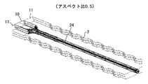
図1乃至図3に基づいて第1の実施形態を説明する。まず、図3に基づいて、本実施形態における微小液滴生成システム1の概要を説明する。微小液滴生成システム1は、微小流路構造体2と、この微小流路構造体2に供給する流体が収容された流体タンク3、4と、各流体タンク3、4から流体を供給するポンプ5、6と、微小流路構造体2により生成された微小液滴を回収する回収タンク7を有している。
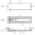
流路パターンを有する微小流路構造体2は、図1及び図2に示すように、2枚のパイレックス(登録商標)ガラス板8、9を張り合わせて構成されている。図1、図2においてハッチング表示はガラス間の融着面を表しており、図1では上側のガラス板9は分かりやすいように破線で表示している。
Hereinafter, describing the implementation embodiments of the present invention with reference to FIG. The first to third embodiments are shown as reference examples.
The first embodiment will be described with reference to FIGS. First, based on FIG. 3, the outline | summary of the micro droplet production |
As shown in FIGS. 1 and 2, the
下側のガラス板8には、ガラスエッチング法により流路がパターニングされている。図1に示すように、中央部に1つの流体(分散相)を導入する流体導入流路10が形成されており、流体導入流路10の両側には、流体導入流路10に導入される流体とは相溶性の無い(相溶性が実質的に無い場合を含む)流体(連続相)を導入する流体導入流路11、11が形成されている。
The
ここで、「相溶性の無い流体」とは、2種の流体の双方への溶解度が10%以下である流体同士のことを示す。
「分散相」とは、本発明の液滴化手段により液滴化される流体のことを示す。「連続相」とは、本発明の液滴化手段で発生した液滴を分散させる媒体の流体のことを示す。
これらの流体導入流路10、11に連通して、各流体が合流する合流流路12が形成されている。合流流路12における合流始点12aの流体進行方向(矢印F方向)下流側近傍には、両側から台形状に突出して合流流路12の流路断面積を変化させる(ここでは狭くする)凸構造14が対向して形成されている。
凸構造14の形成位置は、分散相の液柱が不安定となって液滴化する領域における、その液滴化をコントロールできる位置に設定されている。凸構造14による微小液滴形成作用については、後の実施形態の中で説明する。流路断面積を変化させる構成は凹構造でもよい。
図2に示すように、上側のガラス板9には、上記流路パターンに対応して、流体導入流路10に連通する流体導入口15、流体導入流路11、11に連通する流体導入口16、16、共通出口部13が形成されている。
Here, “fluids that are not compatible” indicate fluids having a solubility in both of the two fluids of 10% or less.
“Dispersed phase” refers to a fluid that is formed into droplets by the droplet forming means of the present invention. “Continuous phase” refers to a fluid of a medium in which droplets generated by the droplet forming means of the present invention are dispersed.
A merging
The formation position of the
As shown in FIG. 2, the
流路材料は石英ガラスに限定するものではなく、連続相または分散相により溶解しない樹脂などでもよい。流路サイズは、最終生成物の用途によって異なるが、本発明の効果が発現するためには、流路の幅、深さが10−1000μmの範囲である。
ガラスエッチング法により流路を形成する場合は、流路断面積を変化させる凹凸構造は、上述のように流路側面または流路底面、流路天井面に形成可能である。流路底面に形成する場合は2段エッチングにより作成することが可能である。
流路断面の形状は円形が望ましいが、流路を構成する部材の加工の都合により長方形などの多角形や略多角形などであってもよい。流路断面積は10.0〜10,000[μm^2]の間で変化することが望ましい。凹凸部における流路断面積は、流体導入口の断面積より大きくなっても小さくなってもよい。
また、液(流体)の供給はポンプによる圧力送液方式が適当である。図1に示すように、液滴分散体17は、合流流路12の下流側端部に位置する共通出口部13より回収タンク7に回収される。
The flow path material is not limited to quartz glass, and may be a resin that does not dissolve in the continuous phase or the dispersed phase. The channel size varies depending on the use of the final product, but the width and depth of the channel are in the range of 10 to 1000 μm in order to achieve the effects of the present invention.
When the flow path is formed by the glass etching method, the uneven structure that changes the flow path cross-sectional area can be formed on the flow path side surface, the flow path bottom surface, or the flow path ceiling surface as described above. When it is formed on the bottom surface of the flow path, it can be formed by two-stage etching.
The shape of the cross section of the flow path is preferably circular, but may be a polygon such as a rectangle or a substantially polygon for convenience of processing the members constituting the flow path. The cross-sectional area of the flow path is desirably changed between 10.0 to 10,000 [μm ^ 2]. The cross-sectional area of the channel in the concavo-convex portion may be larger or smaller than the cross-sectional area of the fluid inlet.
In addition, a pressure liquid feeding system using a pump is appropriate for supplying the liquid (fluid). As shown in FIG. 1, the
図4に第2の実施形態を示す。なお上記実施形態と同一部分は同一符号で示し、特に必要がない限り既にした構成上及び機能上の説明は省略して要部のみ説明する(以下の他の実施形態おいて同じ)。
本実施形態では、流路天井面に合流流路12の流路断面積を変化させる凸構造18を形成している。すなわち、凸構造18は上側のガラス板9に形成されている。
従って、本実施形態における微小流路構造体2は、凸構造18、導入口15、16及び共通出口部13をガラス板9に形成し、これを下側のガラス板8に貼り合わせた構成である。
FIG. 4 shows a second embodiment. Note that the same parts as those in the above embodiment are denoted by the same reference numerals, and unless otherwise specified, description of the configuration and functions already described is omitted, and only the main part will be described (the same applies to other embodiments below).
In this embodiment, the
Therefore, the
図5に第3の実施形態を示す。本実施形態では、液滴化する流体の液柱を複数同時に導入し、微小液滴の生産性を上げることを目的としている。
分散相の流体導入流路10と、連続相の流体導入流路11が、流体の進行方向と直交する方向(ガラス板の幅方向)に流体の種類毎に交互に複数並列されている。また、その並列構成は、合流流路12の壁面に接する端部の流体は連続相となるように設定されている。
導入流路が複数である場合、合流流路12の流路断面積を変化させる凹凸構造は流路底面もしくは天井面に存在し、各流路に同等の流路断面積の変化を与えることが望ましい。
この観点から、本実施形態では、上側のガラス板9に凸構造20を形成している。3つ流路に対して1つの凸構造20が同等の流路断面積の変化(微小液滴化作用)を与える。
FIG. 5 shows a third embodiment. In the present embodiment, an object is to simultaneously introduce a plurality of liquid columns of fluid to be formed into droplets, thereby increasing the productivity of micro droplets.
A plurality of dispersed-phase
When there are a plurality of introduction channels, the uneven structure that changes the channel cross-sectional area of the merging
From this viewpoint, in this embodiment, the
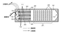
図6及び図7に第4の実施形態を示す。本実施形態では、合流流路12に流路断面積が流体進行方向に周期的に変化する領域21が存在することを特徴とする。
図6に示すように、領域21には、凸構造20が流体進行方向に等間隔に複数設けられており、その結果、凹凸構造が2回以上の周期構造をなしている。周期の繰り返し数は多い程望ましいが、液滴化が十分安定に行われるためには繰り返し回数は10以上100未満が望ましい。但し、これに限定されるものではない。
図7に示すように、微小流路において、合流流路12の壁22に接する端部の流体23は必ず連続相である。
6 and 7 show a fourth embodiment. The present embodiment is characterized in that a
As shown in FIG. 6, a plurality of
As shown in FIG. 7, the fluid 23 at the end in contact with the
次に、合流流路12における流路断面積の変化に基づく微小液滴化の作用を詳細に説明する。
本発明は、既に公知である、柱状流体の不安定化現象を微小流路内において効率よく実現させるものである。以下、図8を用いて液滴化現象を説明する。
(液滴化現象)
液柱の均一液滴化現象は、非特許文献1に説明されるように、静止流体中に、相溶性のない、無限に長い液柱が存在している場合、液柱が最も不安定になる波長条件λは、液柱直径d(jet)を用いて下記の式(1)で表される。
λ=4.5d(jet)・・・・・(1)
これは、前記無限に長い液柱ではなく、ある貫通孔より排出された、初速度を持つ液体が静止または流動流体中に液柱状態として放出された場合にも成立する。ここで、発生する擾乱現象の周波数fは、液柱の速度をvとした場合下記の式(2)で表すことができる。この不安定化により液柱はその形をとどめることが不可能となり、(1)の周期毎の液柱体積分が液滴となる。
f=v/λ・・・・・(2)
Next, the action of microdroplet formation based on the change in the cross-sectional area of the flow path in the merging
The present invention efficiently realizes the well-known phenomenon of columnar fluid destabilization in a microchannel. Hereinafter, the droplet formation phenomenon will be described with reference to FIG.
(Dropping phenomenon)
As explained in
λ = 4.5d (jet) (1)
This is true even when the liquid having an initial velocity discharged from a certain through-hole is discharged as a liquid column state into a stationary or flowing fluid instead of the infinitely long liquid column. Here, the frequency f of the disturbance phenomenon that occurs can be expressed by the following equation (2), where v is the velocity of the liquid column. This destabilization makes it impossible for the liquid column to retain its shape, and the liquid column volume integral for each period of (1) becomes a droplet.
f = v / λ (2)
また、非特許文献2で説明されるように、実験的に安定に均一粒子を形成する条件を導いた結果、下記の式(3)の条件において安定的に均一粒子を形成することが可能であるとしている。
3.5<λ/d(jet)<7.0・・・・・(3)
式(3)における上限値(3.5)及び下限値(7.0)は、流体の種類により変動しうる値であり、上限値は3.0、下限値は10.0程度でも成立するが、3.0〜3.5の間及び7.0〜10.0の間の条件は遷移領域であり、液滴径がばらつく場合もあった。
更には、非特許文献3で説明されるように、エネルギー保存則を基に、貫通孔より排出される液が、液柱を形成する最小ジェットV(min)速度は下記の式(4)のように表現される。
v(min)=(8σ/ρd(jet))^(1/2)・・・(4)
式(4)において、σは液の表面張力、ρは液密度、d(jet)は液柱の直径を表す。式(1)から式(4)の条件式はこのような現象を再現するための条件を推定するために有用であるが、本発明者らは、これらの関係式は液物質の種類、混合物、分散物等によって変動し得ることを確認している。
Further, as described in
3.5 <λ / d (jet) <7.0 (3)
The upper limit (3.5) and lower limit (7.0) in equation (3) are values that can vary depending on the type of fluid, and the upper limit is 3.0 and the lower limit is about 10.0. However, the condition between 3.0 to 3.5 and 7.0 to 10.0 is a transition region, and the droplet diameter may vary.
Furthermore, as explained in
v (min) = (8σ / ρd (jet)) ^ (1/2) (4)
In Equation (4), σ represents the surface tension of the liquid, ρ represents the liquid density, and d (jet) represents the diameter of the liquid column. Although the conditional expressions of the expressions (1) to (4) are useful for estimating the conditions for reproducing such a phenomenon, the present inventors indicate that these relational expressions are the types of liquid substances and mixtures. It has been confirmed that it can vary depending on the dispersion.
上記条件式により推定された条件に基づいて液滴化を行う場合、一つの液柱において時間的に状態が変化したり、隣り合う液柱の状態がそれぞれ異なったりするため、その結果として不安定化の進行状態が刻々異なり、均一な径の微小液滴を大量に生産することは極めて困難である。
そこで、本発明は、合流流路12の流路断面積を変化させて2流体の界面に擾乱を意図的且つ画一的に誘起し、微妙な条件変化による影響が生じる余地が存在しないようにし、これにより液滴径の安定均一化を実現しようとするものである。
換言すれば、柱状流体の不安定化現象を利用して、径の不均一さが発現する前にその現象をコントロールしようとするものである。
この考えの下、上記各実施形態における凸構造14、凸構造18、凸構造20及び凹凸周期構造が形成されている。
When droplet formation is performed based on the conditions estimated by the above conditional expression, the state changes temporally in one liquid column or the state of adjacent liquid columns differs, resulting in instability. It is extremely difficult to mass-produce micro droplets having a uniform diameter because the state of progress of crystallization changes every moment.
In view of this, the present invention intentionally and uniformly induces disturbance at the interface of the two fluids by changing the cross-sectional area of the merging
In other words, the instability phenomenon of the columnar fluid is used to control the phenomenon before the non-uniformity of the diameter appears.
Based on this idea, the
図9に基づいて、凹凸構造による液滴化現象の原理を説明する。
図9(a)に示すように、流路を流れる流体の進行方向に法線を持つ平面で流路の断面を見たとき、一定流量で流路を通過する流体の速度は、流路の断面積に反比例する関係がある。すなわち、断面Aでは流速は速くなり、断面Bでは遅くなる。
流路の壁面に凹凸構造が存在し、その影響により流路の断面積が位置によって変動するとき、前記流路に、流体を一定流量で通過させると、流体の速度は位置によって変動することになる。
前記凹凸構造を持つ微小流路に、図9(b)に示すように、相溶性のない分散相流体及び連続相流体を流通させた場合に、上記断面積の変動によって両流体に速度変動をもたらす結果となった。
本発明は、この現象を利用し、上記柱状流体の不安定化現象を安定的に効率よく実現させるものである。
Based on FIG. 9, the principle of the droplet formation phenomenon by the concavo-convex structure will be described.
As shown in FIG. 9A, when the cross section of the flow path is viewed on a plane having a normal line in the traveling direction of the fluid flowing through the flow path, the velocity of the fluid passing through the flow path at a constant flow rate is There is a relationship inversely proportional to the cross-sectional area. That is, the flow velocity is faster in the cross section A and slower in the cross section B.
When a concavo-convex structure is present on the wall surface of the flow path, and the cross-sectional area of the flow path varies depending on the position due to the influence, if the fluid passes through the flow path at a constant flow rate, the speed of the fluid varies depending on the position. Become.
As shown in FIG. 9B, when the incompatible dispersed phase fluid and continuous phase fluid are circulated through the minute flow path having the concavo-convex structure, speed fluctuations are caused in both fluids due to the change in the cross-sectional area. The result was brought.
The present invention utilizes this phenomenon to stably and efficiently realize the above-mentioned columnar fluid instability phenomenon.
これを第4の実施形態における構成に当てはめて考えると、図10に示すように、周期構造を有する流路に導入された分散相は連続相中で液柱を形成し、領域21における凹凸周期構造によって2流体の界面に擾乱を誘起する。これによって、分散相24は液滴化し、微小液滴25が生成する。
図9では、流体の進行方向において対称に凹凸の周期構造が存在するモデルを示したが、合流流路12の一側面、底面または天井面のいずれかに存在しても、流路断面積の変化による擾乱誘起作用は同様に生じる。
また、図11に示すように、分散相および連続相が交互に配列された系においても凹凸周期構造によって同様の現象が成立する。
凹凸周期構造が各柱状流体に対して均等に作用するので、各分散相から生成する微小液滴は、均一な径となる。
周期構造に比べて単一の凸構造又は凹構造の場合には、径の均一化の精度は劣るが、上記「擾乱を意図的且つ画一的に誘起し」てなる作用による均一安定化機能は享受できる。
When this is applied to the configuration in the fourth embodiment, as shown in FIG. 10, the dispersed phase introduced into the flow path having the periodic structure forms a liquid column in the continuous phase, and the uneven period in the
Although FIG. 9 shows a model in which an irregular periodic structure exists symmetrically in the fluid traveling direction, even if it exists on one side, bottom, or ceiling of the merging
In addition, as shown in FIG. 11, the same phenomenon is realized by the uneven periodic structure even in a system in which dispersed phases and continuous phases are alternately arranged.
Since the concavo-convex periodic structure acts evenly on each columnar fluid, the fine droplets generated from each dispersed phase have a uniform diameter.
In the case of a single convex structure or concave structure compared to the periodic structure, the accuracy of uniforming the diameter is inferior, but the uniform stabilizing function by the action of “inducing disturbances intentionally and uniformly” above. Can enjoy.
レイリーの不安定性原理によれば、最も液柱が不安定になる擾乱の波長は、分散相の液柱直径のおよそ4.5倍であり、3.0倍〜10.0倍の間で液滴化は安定に成立するとされている。液柱の直径は、連続相の速度を増減させることによって減少させたり増加させたりすることが可能である。
従って、周期構造の波長が、分散相最細部(合流直前における円相当直径)の3.0〜10.0倍の範囲となることが望ましい。より好ましくは3.5倍〜7.0倍の間である。
According to Rayleigh's instability principle, the wavelength of the disturbance at which the liquid column becomes most unstable is about 4.5 times the liquid column diameter of the dispersed phase, and the liquid wavelength is between 3.0 times and 10.0 times. Dropping is said to be stable. The diameter of the liquid column can be reduced or increased by increasing or decreasing the velocity of the continuous phase.
Therefore, it is desirable that the wavelength of the periodic structure be in the range of 3.0 to 10.0 times the finest details of the dispersed phase (equivalent circle diameter immediately before joining). More preferably, it is between 3.5 times and 7.0 times.
凹凸の周期構造の形状としては、図12に示すように、一辺と隣接する一辺の角度が直角である矩形波形状はもちろんのこと、図13に示す矩形波状の形状としてもよい。これらの形状は、所定の速度条件において、サテライトが影響しない領域になるよう適宜決定されるものである。
矩形波状とは、一辺と隣接する一辺の角度が直角ではない形状(例えば図13(a))を含み、三角波形(例えば図13(b))、曲面波形(例えば図13(c))もこれに該当する。
図14に示すように、2以上の任意の矩形波状の組み合わせとしてもよい。この場合、2以上の任意形状26及び27を組み合わせた一組28をもって1周期構造とみなすものとする。これら形状も所定の速度条件において、サテライトが影響しない領域になるよう適宜決定されるものである。
As shown in FIG. 12, the shape of the irregular periodic structure may be a rectangular wave shape shown in FIG. 13 as well as a rectangular wave shape in which the angle between one side and one side is a right angle. These shapes are appropriately determined so as to be an area where the satellite does not influence under a predetermined speed condition.
The rectangular wave shape includes a shape in which the angle between one side and an adjacent side is not a right angle (for example, FIG. 13A), and also includes a triangular waveform (for example, FIG. 13B) and a curved surface waveform (for example, FIG. 13C). This is the case.
As shown in FIG. 14, it may be a combination of two or more arbitrary rectangular waves. In this case, a set 28 in which two or more
図15に第5の実施形態を示す。
本実施形態では、液滴形成流路の後方(流体進行方向下流)に、液滴表面に膜を形成するための工程を備えることを特徴とする。より具体的には、主流路29に、分岐流路30より膜形成材料31を含む流体を導入する。このとき材料の液滴表面への析出や表面化学反応による膜形成手段を適用することができる。
既に説明した実施形態の構成において、分岐流路30は周期構造の下流に設けられる。分岐流路30と、膜形成材料31を供給する図示しない手段とにより、液滴の表面に膜を形成するための手段が構成される。
膜形成工程は、必ずしも流路系で行う必要は無く、流路出口にて回収されたエマルションに、一般的なカプセル化工程を施してもよい。
FIG. 15 shows a fifth embodiment.
In the present embodiment, a process for forming a film on the surface of the droplet is provided behind the droplet formation channel (downstream in the fluid traveling direction). More specifically, a fluid containing the
In the configuration of the embodiment described above, the
The film forming step is not necessarily performed in the flow channel system, and a general encapsulation step may be performed on the emulsion collected at the flow channel outlet.
液滴形成方法により作成された微小液滴を固化して作成された微粒子をトナーとして用いた場合、分散値が5%以下であれば画質の粒状性及び粉体としての流動性が優れたトナーを提供することが可能となる。
第5の実施形態における液滴形成方法により作成され、分散値が5%以下であるマイクロカプセルを電気泳動マイクロカプセルとして用いた場合、粒子径の均一性により、白色度の高い電子ペーパーを提供することが可能となる。
When fine particles produced by solidifying fine droplets produced by a droplet forming method are used as toner, a toner having excellent image quality granularity and fluidity as powder as long as the dispersion value is 5% or less Can be provided.
When a microcapsule produced by the droplet forming method in the fifth embodiment and having a dispersion value of 5% or less is used as an electrophoretic microcapsule, an electronic paper with high whiteness is provided due to the uniformity of the particle diameter. It becomes possible.
以下に本発明を実施する上での構成・材料に関する好適指針を示す。
(流路構造、流体導入口、流体排出口)
パイレックス(登録商標)ガラスに通常のガラスエッチング法により流路パターンを形成し、流体の出入り口を持つ、もう一枚のパイレックス(登録商標)ガラスを重ね合わせ、位置合わせ後、熱融着にて接合し、出入り口を有する流路が形成される。
(流体搬送ポンプ)
流体を搬送する手段としては、シリンジポンプ、不活性ガスによる加圧式送液方式、蠕動ポンプ、ダイアフラムポンプがあるが、これらに限られるものではない。マイクロメートルオーダーの流路に液体を導入するため、圧力損失がおよそ100kPa−1000kPa程度の加圧が可能なポンプを利用する。
以下の実施例においては、不活性ガスによる加圧式送液方式を用いた。不活性ガスとしては、使用する薬液に対し不活性であればよく、以下の実施例においては、窒素ガスを用いた。
The following is a suitable guideline regarding the constitution and materials for carrying out the present invention.
(Channel structure, fluid inlet, fluid outlet)
A flow pattern is formed on Pyrex (registered trademark) glass by a normal glass etching method, and another Pyrex (registered trademark) glass with a fluid inlet / outlet is overlaid, aligned, and bonded by thermal fusion Thus, a flow path having an entrance is formed.
(Fluid transfer pump)
Means for conveying the fluid include, but are not limited to, a syringe pump, a pressurized liquid feeding method using an inert gas, a peristaltic pump, and a diaphragm pump. In order to introduce the liquid into the micrometer order flow path, a pump capable of pressurization with a pressure loss of about 100 kPa to 1000 kPa is used.
In the following examples, a pressurized liquid feeding method using an inert gas was used. The inert gas may be inert to the chemical solution used, and nitrogen gas was used in the following examples.
(配管、接続)
配管は使用する薬液に不活性であり、溶解しないことが必要である。更に、耐圧性が必要である。薬液の種類に依存するが、材質としては、テフロン(登録商標)、各種金属、PEEK等があるが、これらに限られるものではない。以下の実施例においてはPEEK製の配管を使用した。
配管と配管、配管と液タンク、配管と流路構造体などの接続には、使用する薬液に不活性であり、溶解しないこと、漏れのないことが必要である。更に、耐圧性が必要であり、使用条件によって選択される。
接続方式としては、ゴム製Oリング、テフロン(登録商標)樹脂製Oリングによる接続、接着剤による接続、フランジによる接続などがあるが、これらに限るものではない。材質としては、薬液の種類に依存するが、テフロン(登録商標)、各種金属、PEEK等があるが、これらに限られるものではない。以下の実施例においてはPEEK製のフランジ式接続方式を使用した。これらは、高圧液体クロマトグラフィー等に用いられる一般的に入手可能なものを用いた。
(造粒工程概観)
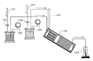
図16に、以下の実施例において用いた造粒工程の概要を示す。乾燥窒素による圧力送液機構121により連続相及び分散相が微小流路構造体122へと導入される。配管123と微小流路構造体122はコネクタにより接続されている。
生成したエマルションは回収容器124へ捕集された。連続相及び分散相の流量は圧力送液機構の配管に設置されたニードルバルブ125によって行った。各流体に与えられる圧力は圧力ゲージ126により確認した。更に、微小流路構造体及び配管、貯蔵タンクは温度調節機構により−20度から150度まで温度を調節することが可能であった。
(Piping, connection)
The piping is inert to the chemical solution used and must not dissolve. Furthermore, pressure resistance is required. Although depending on the type of the chemical solution, the material includes, but is not limited to, Teflon (registered trademark), various metals, PEEK, and the like. In the following examples, PEEK piping was used.
For connecting pipes and pipes, pipes and liquid tanks, pipes and flow channel structures, etc., it is necessary to be inert to the chemical solution to be used and not to be dissolved or leaked. Furthermore, pressure resistance is necessary, and it is selected according to use conditions.
Examples of the connection method include, but are not limited to, a connection using a rubber O-ring, a Teflon (registered trademark) resin O-ring, a connection using an adhesive, and a connection using a flange. The material depends on the type of the chemical solution, but includes, but is not limited to, Teflon (registered trademark), various metals, and PEEK. In the following examples, a PEEK flange connection method was used. These generally used were used for high pressure liquid chromatography and the like.
(Overview of granulation process)
In FIG. 16, the outline | summary of the granulation process used in the following examples is shown. The continuous liquid phase and the dispersed phase are introduced into the
The produced emulsion was collected in the
(分散相及び連続相材料、分散剤、界面活性剤)
本発明の方式においては、分散相及び連続相は、相溶性が10%以下であれば適用可能であるが、1%以下の相溶性であることがより好ましい。液滴化の際には、通常の分散剤または界面活性剤を必要としないが、回収時に合一の可能性があるため、臨界濃度以上に含有させておく、または後工程によって添加することが望ましい。
分散剤の材料としては、ゼラチン、ポリビニルアルコールが挙げられる。更に、アルキルベンゼンスルホン酸塩、αーオレフィンスルホン酸塩、リン酸エステルなどの陰イオン界面活性剤、アルキルアミン塩、アミノアルコール脂肪酸誘導体、ポリアミン脂肪酸誘導体、イミダゾリンなどのアミン塩型や、アルキルトリメチルアンモニム塩、ジアルキルジメチルアンモニウム塩、アルキルジメチルベンジルアンモニウム塩、ピリジニウム塩、アルキルイソキノリニウム塩、塩化ベンゼトニウムなどの四級アンモニウム塩型の陽イオン界面活性剤、脂肪酸アミド誘導体、多価アルコール誘導体などの非イオン界面活性剤、例えばアラニン、ドデシルジ(アミノエチル)グリシン、ジ(オクチルアミノエチル)グリ
シンやNーアルキルーN,Nージメチルアンモニウムべタインなどの両性界面活性剤が挙げられる。
(Dispersed phase and continuous phase materials, dispersants, surfactants)
In the system of the present invention, the dispersed phase and the continuous phase can be applied if the compatibility is 10% or less, but more preferably 1% or less. When forming droplets, a normal dispersant or surfactant is not required, but since there is a possibility of coalescence at the time of recovery, it may be contained at a critical concentration or added in a later step. desirable.
Examples of the material for the dispersant include gelatin and polyvinyl alcohol. In addition, anionic surfactants such as alkylbenzene sulfonates, α-olefin sulfonates, phosphate esters, alkylamine salts, aminoalcohol fatty acid derivatives, polyamine fatty acid derivatives, amine salt types such as imidazoline, and alkyltrimethylammonium Non-cationic surfactants such as salts, dialkyldimethylammonium salts, alkyldimethylbenzylammonium salts, pyridinium salts, alkylisoquinolinium salts, benzethonium chloride, fatty acid amide derivatives, polyhydric alcohol derivatives, etc. Examples of the ionic surfactant include amphoteric surfactants such as alanine, dodecyldi (aminoethyl) glycine, di (octylaminoethyl) glycine and N-alkyl-N, N-dimethylammonium betaine.
またフルオロアルキル基を有する界面活性剤を用いることにより、非常に少量でその効果をあげることができる。好ましく用いられるフルオロアルキル基を有するアニオン性界面活性剤としては、炭素数2〜10のフルオロアルキルカルボン酸及びその金属塩、パーフルオロオクタンスルホニルグルタミン酸ジナトリウム、3一[オメガーフルオロアルキル(C6〜C11)オキシ]ー1ーアルキル(C3〜C4)スルホン酸ナトリウム、3ー[オメガーフルオロアルカノイル(C6〜C8)一Nーエチルアミノ]ー1−プロパンスルホン酸ナトリウム、フルオロアルキル(C11〜C20)カルボン酸及び金属塩、パーフルオロアルキルカルボン酸(C7〜C13)及びその金属塩、パーフルオロアルキル(C4〜C12)スルホン酸及びその金属塩、パーフルオロオクタンスルホン酸ジエタノールアミド、NープロピルーN一(2ヒドロキシエチル)パーフルオロオクタンスルホンアミド、パーフルオロアルキル(C6〜C10)スルホンアミドプロピルトリメチルアンモニウム塩、パーフルオロアルキル(C6〜C10)ーNーエチルスルホニルグリシン塩、モノパーフルオロアルキル(C6〜C16)エチルリン酸エステルなどが挙げられる。 Further, by using a surfactant having a fluoroalkyl group, the effect can be obtained in a very small amount. Preferred anionic surfactants having a fluoroalkyl group include fluoroalkyl carboxylic acids having 2 to 10 carbon atoms and metal salts thereof, disodium perfluorooctanesulfonyl glutamate, 31- [omega-fluoroalkyl (C6-C11) Oxy] -1-alkyl (C3-C4) sodium sulfonate, 3- [omega-fluoroalkanoyl (C6-C8) mono-N-ethylamino] -1-propanesulfonic acid sodium, fluoroalkyl (C11-C20) carboxylic acid and metal salt, Perfluoroalkylcarboxylic acid (C7 to C13) and its metal salt, perfluoroalkyl (C4 to C12) sulfonic acid and its metal salt, perfluorooctanesulfonic acid diethanolamide, N-propyl-N- (2hydroxyethyl) -Fluorooctanesulfonamide, perfluoroalkyl (C6-C10) sulfonamidopropyltrimethylammonium salt, perfluoroalkyl (C6-C10) -N-ethylsulfonylglycine salt, monoperfluoroalkyl (C6-C16) ethyl phosphate, etc. Is mentioned.
商品名としては、サーフロンSー111、S−112、Sー113(旭硝子社製)、フロラードFCー93、FCー95、FCー98、FCーl29(住友3M社製)、ユニダインDS一101、DSーl02、(タイキン工莱社製)、メガファックFーll0、Fーl20、F一113、Fー191、Fー812、F−833(大日本インキ社製)、エクトップEF一102、l03、104、105、112、123A、123B、306A、501、201、204、(トーケムプロダクツ社製)、フタージェントF−100、F150(ネオス社製)などが挙げられる。
また、カチオン界面活性剤としては、フルオロアルキル基を右する脂肪族一級、二級もしくは二級アミン酸、パーフルオロアルキル(C6一C10)スルホンアミドプロピルトリメチルアンモニウム塩などの脂肪族4級アンモニウム塩、ベンザルコニウム塩、塩化ベンゼトニウム、ピリジニウム塩、イミダゾリニウム塩、商品名としてはサーフロンSーl21(旭硝子社製)、フロラードFC−135(住友3M社製)、ユニダインDSー202(ダイキンエ業杜製)、メガファックF−150、F−824(大日本インキ社製)、エクトップEFーl32(トーケムプロダクツ社製)、フタージェントF一300(ネオス社製)などが挙げられる。
Product names include Surflon S-111, S-112, S-113 (Asahi Glass Co., Ltd.), Florard FC-93, FC-95, FC-98, FC-129 (Sumitomo 3M Co., Ltd.), Unidyne DS-1101 , DS-102, (Taikin Kogyo Co., Ltd.), Megafuck F-l0, F-l20, F-113, F-191, F-812, F-833 (Dainippon Ink Co., Ltd.), Xtop EF-ichi 102, 103, 104, 105, 112, 123A, 123B, 306A, 501, 201, 204 (manufactured by Tochem Products), and Fagento F-100, F150 (manufactured by Neos).
Further, as the cationic surfactant, aliphatic quaternary ammonium salts such as aliphatic primary, secondary or secondary amic acid, perfluoroalkyl (
高分子系保護コロイドにより分散液滴の安定化を調節しても良い。例えばアクリル酸、メタクリル酸、αーシアノアクリル酸、α−シアノメタクリル酸、イタコン酸、クロトン酸、フマール酸、マレイン酸または無水マレイン酸などの酸類、あるいは水酸基を含有する(メタ)アクリル系単量体、例えばアクリル酸β一ヒドロキシエチル、メタクリル酸β一ヒドロキシエチル、アクリル酸βーヒドロキシプロビル、メタクリル酸β一ヒドロキシプロピル、アクリル酸γーヒドロキシプロピル、メタクリル酸γ一ヒドロキシプロピル、アクリル酸3−クロロ2−ヒドロキシプロビル、メタクリル酸3ークロロー2一ヒドロキシプロピル、ジエチレングリコールモノアクリル酸エステル、ジエチレングリコールモノメタクリル酸エステル、グリセリンモノアクリル酸エステル、グリセリンモノメタクリル酸エステル、N−メチロールアクリルアミド、Nーメチロールメタクリルアミドなど、ビニルアルコールまたはビニルアルコールとのエ一テル類、例えばビニルメチルエーテル、ビニルエチルエーテル、ビニルプロピルエーテルなど、またはビニルアルコールとカルボキシル基を含有する化合物のエステル類、例えば酢酸ビニル、プロピオン酸ビニル、酪酸ビニルなど、アクリルアミド、メタクリルアミド、ジアセトンアクリルアミドあるいはこれらのメチロール化合物、アクリル酸クロライド、メタクリル酸クロライドなどの酸クロライド類、ピニルビリジン、ビニルピロリドン、ビニルイミダゾール、エチレンイミンなどの窒素原子、またはその複素環を有するものなどのホモポリマーまたは共重合体、ポリオキシエチレン、ポリオキシプロピレン、ポリオキシエチレンアルキルアミン、ポリオキシプロピレンアルキルアミン、ポリオキシエチレンアルキルアミド、ポリオキシプロピレンアルキルアミド、ポリオキシエチレンノニルフエニルエーテル、ポリオキシエチレンラウリルフェニルエーテル、ポリオキシエチレンステアリルフェニルエステル、ポリオキシエチレンノニルフェニルエステルなどのポリオキシエチレン系、メチルセルロース、ヒドロキシエチルセルロース、ヒドロキシプロピルセルロースなどのセルロース類などが使用できる。
分散剤を使用した場合は、分散剤が液滴表面に付着したまま使用することも可能であるが、液滴の絶縁性が重要である場合は、これを除去する場合がある。
The stabilization of the dispersed droplets may be adjusted by a polymer protective colloid. For example, acrylic acid, methacrylic acid, α-cyanoacrylic acid, α-cyanomethacrylic acid, itaconic acid, crotonic acid, fumaric acid, maleic acid or maleic anhydride or other (meth) acrylic monomer containing a hydroxyl group, For example, β-hydroxyethyl acrylate, β-hydroxyethyl methacrylate, β-hydroxypropyl acrylate, β-hydroxypropyl methacrylate, γ-hydroxypropyl acrylate, γ-hydroxypropyl methacrylate, 3-chloro-2-acrylate -Hydroxypropyl, 3-chloro-2-methacrylic acid methacrylate, diethylene glycol monoacrylate, diethylene glycol monomethacrylate, glycerol monoacrylate, glycerol monomethacrylate, N -Methylol acrylamide, N-methylol methacrylamide, etc., vinyl alcohol or ethers with vinyl alcohol, such as vinyl methyl ether, vinyl ethyl ether, vinyl propyl ether, or esters of compounds containing vinyl alcohol and carboxyl groups For example, vinyl acetate, vinyl propionate, vinyl butyrate, acrylamide, methacrylamide, diacetone acrylamide or their methylol compounds, acid chlorides such as acrylic acid chloride, methacrylic acid chloride, pinylviridine, vinylpyrrolidone, vinylimidazole, ethyleneimine Homopolymers or copolymers such as those having a nitrogen atom or its heterocyclic ring, polyoxyethylene, polyoxypropylene, Oxyethylene alkylamine, polyoxypropylene alkylamine, polyoxyethylene alkylamide, polyoxypropylene alkylamide, polyoxyethylene nonyl phenyl ether, polyoxyethylene lauryl phenyl ether, polyoxyethylene stearyl phenyl ester, polyoxyethylene nonylphenyl Polyoxyethylenes such as esters, celluloses such as methyl cellulose, hydroxyethyl cellulose, and hydroxypropyl cellulose can be used.
When a dispersant is used, the dispersant can be used while adhering to the surface of the droplet. However, if the insulation of the droplet is important, it may be removed.
(カプセル化工程)
コアセルべーション法、紫外線硬化法等が適用可能である。以下の実施例においては、単純コアセルべーション法を用いた。より具体的には、45度に暖めた10%ゼラチン水溶液中に、流路構造体より排出されたエマルションを導入し、これに徐々にエタノールを加える。エタノール濃度を50%程度とし、これを冷却することによってコロイドはマイクロカプセル化した。
(液滴固化工程)
架橋反応可能なモノマー及びラジカル重合反応開始材を分散相に含有し、紫外線または熱により重合反応させ、固化することが可能である。
(粒子径評価手段)
回収された液滴またはカプセルを一部採取して、プレパラート上で顕微鏡により観察し、画像解析法を用いて1000個の粒子画像より平均粒子径及び分散値(直径の標準偏差)/(直径の平均値)を求めた。
(並列化)
微小流路構造体122は、図17に模式的に示すように、多数並列して稼働する場合、各構造体に均一に流体が送液されるよう、各構造体導入部手前で流量調節機構132を設けた。
(Encapsulation process)
A coacervation method, an ultraviolet curing method, or the like is applicable. In the following examples, the simple coacervation method was used. More specifically, the emulsion discharged from the channel structure is introduced into a 10% gelatin aqueous solution heated to 45 degrees, and ethanol is gradually added thereto. The colloid was microencapsulated by cooling the ethanol concentration to about 50%.
(Droplet solidification process)
It is possible to contain a monomer capable of crosslinking reaction and a radical polymerization reaction initiator in a dispersed phase, and to cause a polymerization reaction by ultraviolet rays or heat to solidify.
(Particle size evaluation means)
A part of the collected droplets or capsules is collected, observed with a microscope on a preparation, and an average particle diameter and dispersion value (standard deviation of diameter) / (diameter of diameter) from 1000 particle images using an image analysis method. The average value was determined.
(Parallelization)
As schematically shown in FIG. 17, when a large number of
さらに検討を重ねた結果、分散相と連続相の流路が合流する部分において、分散相流路の出口部分の形状が液滴の形成に関係することが新たに判明した。
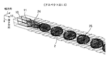
すなわち、分散相と連続相の流路が配置されている方向を幅方向、該幅方向に垂直な方向を深さ方向とした場合、分散相の流路の出口形状(合流流路12との境界形状)を、「深さ方向長さ/幅方向長さ」(アスペクト比)の値が1より大きい断面形状とすることにより、液滴が良好に形成できることを見出した。
第1の流路である流体導入流路10に分散相、第2、3の流路である流体導入流路11に連続相を導入し、深さ方向に凹凸を配置した様子を図22に、流体導入流路10に分散相、流体導入流路11に連続相を導入し、幅方向に凹凸を配置した様子を図23に示す。図22、図23において、分散相の流路が連続相の流路と合流する部分の、出口形状の深さ方向と幅方向との比が重要である。
As a result of further studies, it has been newly found that the shape of the outlet portion of the dispersed phase channel is related to the formation of droplets at the portion where the channel of the dispersed phase and the continuous phase merge.
That is, when the direction in which the flow path of the dispersed phase and the continuous phase is arranged is the width direction and the direction perpendicular to the width direction is the depth direction, the outlet shape of the flow path of the dispersed phase (with the merging flow path 12) It has been found that by setting the (boundary shape) to a cross-sectional shape having a value of “length in the depth direction / length in the width direction” (aspect ratio) larger than 1, droplets can be formed satisfactorily.
FIG. 22 shows a state in which a dispersed phase is introduced into the
この比(アスペクト比)による液滴形成の違いをシミュレーションにより求めた。シミュレーションには、熱流体解析ソフトであるFLUENTを用いて行った。
図24、25、26、27にシミュレーション結果の一例を示す。図24、25は、図22に対応した凹凸が深さ方向に配置されている場合で、図24はアスペクト比が1.5、図25はアスペクト比が0.5のときを示している。
図26、27は、図23に対応した凹凸が幅方向に配置されている場合で、図26はアスペクト比が4、図27はアスペクト比が0.5のときを示している。
図25、図27に示すように、アスペクト比が0.5の場合、液滴25が形成できない。図24、図26に示すようにアスペクト比がある程度大きい場合、液滴25が形成できる。
The difference in droplet formation due to this ratio (aspect ratio) was determined by simulation. The simulation was performed using FLUENT, which is thermal fluid analysis software.
24, 25, 26, and 27 show examples of simulation results. 24 and 25 show the case where the unevenness corresponding to FIG. 22 is arranged in the depth direction. FIG. 24 shows the case where the aspect ratio is 1.5, and FIG. 25 shows the case where the aspect ratio is 0.5.
26 and 27 show the case where the unevenness corresponding to FIG. 23 is arranged in the width direction, FIG. 26 shows the case where the aspect ratio is 4, and FIG. 27 shows the case where the aspect ratio is 0.5.
As shown in FIGS. 25 and 27, when the aspect ratio is 0.5, the
このシミュレーションの結果より、アスペクト比が大きいときに液滴が形成できることがわかる。この理由を図24と図25に示すモデルを用いて説明する。
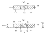
図28(a)に示すように、流体導入流路10においては、分散相24は断面形状が流路と同じ形状であるが、連続相23と合流して層流状態になると、図28(b)に示すように、表面張力により断面が円になろうとし、最終的に円柱を形成する。図24の場合、高アスペクトの縦長の断面から円の断面になるため、深さ方向の上下に隙間が発生する。その隙間に連続相23が入り込む。
From the simulation results, it can be seen that droplets can be formed when the aspect ratio is large. The reason for this will be described with reference to the models shown in FIGS.
As shown in FIG. 28 (a), in the fluid
これに対し、図25の場合、図29に示すように、低アスペクトの横長の断面から円の断面になるため、深さ方向の上下に隙間が発生しない。従って、上下に連続相23が入り込むスペースが無い。
図24の場合、図28(b)に示すように分散相24が連続相23で覆われている状況が発生する。図25の場合、図29(b)に示すように分散相24が連続相23で覆われている状況にならない。液滴が形成されるには、分散相24が連続相23で覆われている状態が必要となる。
図26、27に示す場合も同様の関係となる。
On the other hand, in the case of FIG. 25, as shown in FIG. 29, since the low-aspect laterally long cross section is changed to a circular cross-section, no gap is generated vertically in the depth direction. Therefore, there is no space for the
In the case of FIG. 24, a situation occurs in which the dispersed
The same relationship applies to the cases shown in FIGS.
ここで、どの程度のアスペクト比が液滴形成に必要かが重要である。アスペクト比と液滴形成の関係のシミュレーション結果を表1と表2に示す。表1は幅方向に凹凸がある場合、表2は深さ方向に凹凸がある場合で、連続相の粘度とアスペクト比による液滴形成性の結果である。 Here, what aspect ratio is necessary for droplet formation is important. Tables 1 and 2 show the simulation results of the relationship between the aspect ratio and droplet formation. Table 1 shows the results of droplet formation according to the viscosity and aspect ratio of the continuous phase when there are irregularities in the width direction and Table 2 shows the cases where there are irregularities in the depth direction.

表1の幅方向に凹凸が配置されているときを説明する。アスペクト比が0.5の場合、液滴が形成されないことがわかる。表1のアスペクト比が1の場合より、連続相の粘度が大きいほど液滴が形成されやすくなることがわかる。連続相の粘度は、水の粘度(1cSt)よりも小さくなることはない。
液滴が形成されやすくするため、水あるいはそれに準ずる液体に界面活性剤などを混合するので、粘度が大きくなる場合が多い。また、粘度が大きくなると流路に流しにくくなるので、連続相の粘度が1〜10cStは、シミュレーションの範囲として妥当である。アスペクト比が1より大きくなると、連続相の粘度に関係なく液滴が形成される。
The case where unevenness | corrugation is arrange | positioned in the width direction of Table 1 is demonstrated. It can be seen that no droplet is formed when the aspect ratio is 0.5. From the case of the aspect ratio of 1 in Table 1, it can be seen that the larger the viscosity of the continuous phase, the easier the droplets are formed. The viscosity of the continuous phase will not be less than the viscosity of water (1 cSt).
In order to easily form droplets, a surfactant or the like is mixed with water or a liquid equivalent thereto, so that the viscosity often increases. Moreover, since it becomes difficult to flow into a flow path when a viscosity becomes large, the viscosity of a continuous phase is 1-10 cSt is appropriate as a range of simulation. When the aspect ratio is greater than 1, droplets are formed regardless of the viscosity of the continuous phase.
表2の深さ方向に凹凸が配置されているときを説明する。表1の結果を考慮すると、アスペクト比が0.5で、連続相の粘度が大きい場合、液滴が形成不可能と推定される。また、アスペクト比が1より大きい場合、連続相の粘度に関係なく液滴が形成できると推定される。
今回、連続相の粘度との関係について表にまとめているが、分散相の粘度あるいは分散相と連続相の流速との関係についてもシミュレーションを行っている。連続相の粘度の場合、幅方向に凹凸がある場合のみ僅かに影響が見られたが、分散相の粘度あるいは分散相と連続相の流速については、影響がみられないことを確認している。
実際に液滴を形成する場合、連続相に水そのものを使用することはなく、水に界面活性剤など溶かすことや、水以外の液体を使用するので、粘度は1cStよりも大きくなる。従って、凹凸が幅方向あるいは深さ方向のいずれにおいても、アスペクト比が1より大きければ液滴が形成されることがわかる。
The case where unevenness | corrugation is arrange | positioned in the depth direction of Table 2 is demonstrated. Considering the results shown in Table 1, it is estimated that droplets cannot be formed when the aspect ratio is 0.5 and the viscosity of the continuous phase is large. When the aspect ratio is greater than 1, it is estimated that droplets can be formed regardless of the viscosity of the continuous phase.
This time, the relationship with the viscosity of the continuous phase is summarized in the table, but the simulation is also conducted for the relationship between the viscosity of the dispersed phase or the flow rate of the dispersed phase and the continuous phase. In the case of the viscosity of the continuous phase, a slight effect was observed only when there was unevenness in the width direction, but it was confirmed that there was no effect on the viscosity of the dispersed phase or the flow rate of the dispersed phase and the continuous phase. .
When droplets are actually formed, water itself is not used for the continuous phase, but a surfactant or the like is dissolved in water or a liquid other than water is used, so that the viscosity is greater than 1 cSt. Therefore, it can be seen that droplets are formed if the aspect ratio is greater than 1 in both the width direction and the depth direction.
以上のことより、請求項1においてアスペクト比を1より大きい範囲とした。
アスペクト比の上限に関しては、液柱の上下に隙間が発生すれば上下に連続相が入り込むので、大きいほど良いということになる。実際に高アスペクト比の流路を形成することは難しいので、実際上製造できる上限として捉えることができる。
From the above, the aspect ratio in
Regarding the upper limit of the aspect ratio, if a gap occurs above and below the liquid column, the continuous phase will enter the top and bottom, so the larger the better. Since it is difficult to actually form a flow channel having a high aspect ratio, it can be regarded as an upper limit that can be actually manufactured.
(実施例1)
パイレックス(登録商標)ガラスにエッチングにより流路構造を施した、略矩形波形状凸部単一構造体(図4)を用い液滴化を行った。分散相導入口の断面形の、幅方向長さは20μm、深さ方向長さは40μmであり、凸部の高さは4.9μm、凸部の幅は8.2μmであった。連続相と分散相の合流部は、幅100μm、深さ40μmであった。
分散相としては、アイソパーG(登録商標;エクソンモービル社)に顔料成分を分散した液を用いた。連続相としては、イオン交換水にゼラチンを2.0%溶解した液を用いた。以下の実施例、比較例において、分散相及び連続相の組成は上記のものを用いた。分散相流体に与えた圧力は150kPaであった。また、連続相流体に与えた圧力は320kPaであった。造粒を5時間継続し、得られた液滴の平均直径は48.0μm、分散値は8.2%、収量は21gであった。
Example 1
A droplet was formed using a substantially rectangular wave-shaped convex single structure (FIG. 4) in which a flow channel structure was applied to Pyrex (registered trademark) glass by etching. The cross-sectional shape of the dispersed phase inlet had a width direction length of 20 μm, a depth direction length of 40 μm, a convex portion height of 4.9 μm, and a convex portion width of 8.2 μm. The joining part of the continuous phase and the dispersed phase had a width of 100 μm and a depth of 40 μm.
As the dispersed phase, a liquid in which a pigment component was dispersed in Isopar G (registered trademark; ExxonMobil) was used. As the continuous phase, a solution in which 2.0% gelatin was dissolved in ion-exchanged water was used. In the following examples and comparative examples, the above-described compositions were used for the dispersed phase and the continuous phase. The pressure applied to the dispersed phase fluid was 150 kPa. The pressure applied to the continuous phase fluid was 320 kPa. Granulation was continued for 5 hours. The average diameter of the obtained droplets was 48.0 μm, the dispersion value was 8.2%, and the yield was 21 g.
(実施例2)
パイレックス(登録商標)ガラスにエッチングにより流路構造を施した、略矩形波形状周期構造体(図18;第6の実施形態)を用い液滴化を行った。分散相導入口の断面形の、幅方向長さは20μm、深さ方向長さは40μmであり、周期構造の周期は100μmであった。連続相と分散相の合流部は、幅100μm、深さ40μmであった。
分散相流体に与えた圧力は150kPaであった。連続相流体に与えた圧力は320kPaであった。造粒を5時間継続し、得られた液滴の平均直径は48.0μm、分散値は1.2%、収量は25gであった。
(Example 2)
A droplet was formed using a substantially rectangular wave-shaped periodic structure (FIG. 18; sixth embodiment) in which a flow channel structure was formed by etching on Pyrex (registered trademark) glass. The cross-sectional shape of the dispersed phase inlet has a width direction length of 20 μm, a depth direction length of 40 μm, and the periodic structure has a period of 100 μm. The joining part of the continuous phase and the dispersed phase had a width of 100 μm and a depth of 40 μm.
The pressure applied to the dispersed phase fluid was 150 kPa. The pressure applied to the continuous phase fluid was 320 kPa. Granulation was continued for 5 hours. The average diameter of the obtained droplets was 48.0 μm, the dispersion value was 1.2%, and the yield was 25 g.
(実施例3)
パイレックス(登録商標)ガラスにエッチングにより流路構造を施した、略矩形波形状周期構造体(図6)を用い液滴化を行った。分散相導入口の断面形の、幅方向長さは20μm、深さ方向長さは40μmであり、周期構造の周期は100μmであった。連続相と分散相の合流部は、幅100μm、深さ40μmであった。
分散相流体に与えた圧力は150kPaであった。連続相としては、連続相流体に与えた圧力は320kPaであった。造粒を5時間継続し、得られた液滴の平均直径は45.0μm、分散値は1.8%、収量は142gであった。
(Example 3)
A droplet was formed using a substantially rectangular wave-shaped periodic structure (FIG. 6) in which a flow channel structure was formed by etching on Pyrex (registered trademark) glass. The cross-sectional shape of the dispersed phase inlet has a width direction length of 20 μm, a depth direction length of 40 μm, and the periodic structure has a period of 100 μm. The joining part of the continuous phase and the dispersed phase had a width of 100 μm and a depth of 40 μm.
The pressure applied to the dispersed phase fluid was 150 kPa. As the continuous phase, the pressure applied to the continuous phase fluid was 320 kPa. Granulation was continued for 5 hours. The average diameter of the obtained droplets was 45.0 μm, the dispersion value was 1.8%, and the yield was 142 g.
(実施例4)
パイレックス(登録商標)ガラスにエッチングにより流路構造を施した、略矩形波形状周期構造体(図6)を、図17のように10枚並列で用い、液滴化を行った。分散相導入口の断面形の、幅方向長さは20μm、深さ方向長さは40μmであり、周期構造の周期は100μmであった。連続相と分散相の合流部は、幅100μm、深さ40μmであった。
分散相流体に与えた圧力は250kPaであった。連続相としては、連続相流体に与えた圧力は480kPaであった。造粒を5時間継続し、得られた液滴の平均直径は52.0μm、分散値は4.8%、収量は512gであった。
Example 4
Ten substantially rectangular wave-shaped periodic structures (FIG. 6) obtained by etching a Pyrex (registered trademark) glass with a channel structure by etching were used in parallel as shown in FIG. 17 to form droplets. The cross-sectional shape of the dispersed phase inlet has a width direction length of 20 μm, a depth direction length of 40 μm, and the periodic structure has a period of 100 μm. The joining part of the continuous phase and the dispersed phase had a width of 100 μm and a depth of 40 μm.
The pressure applied to the dispersed phase fluid was 250 kPa. As the continuous phase, the pressure applied to the continuous phase fluid was 480 kPa. Granulation was continued for 5 hours. The average diameter of the obtained droplets was 52.0 μm, the dispersion value was 4.8%, and the yield was 512 g.
(実施例5)
パイレックス(登録商標)ガラスにエッチングにより流路構造を施した、略矩形波形状周期構造体(図19;第7の実施形態)を用い、液滴化を行った。分散相導入口の断面形の、幅方向長さは20μm、深さ方向長さは40μmであり、周期構造の周期は100μmであった。連続相と分散相の合流部は、幅100μm、深さ40μmであった。凹部は深さ5.0μm、長さ12μmであった。凸部は高さ8.0μm、長さは88μmであった。
分散相流体に与えた圧力は110kPaであった。連続相としては、連続相流体に与えた圧力は300kPaであった。造粒を5時間継続し、得られた液滴の平均直径は42.0μm、分散値は0.5%、収量は20gであった。
(Example 5)
The droplets were formed using a substantially rectangular wave-shaped periodic structure (FIG. 19; seventh embodiment) in which a flow channel structure was formed by etching on Pyrex (registered trademark) glass. The cross-sectional shape of the dispersed phase inlet has a width direction length of 20 μm, a depth direction length of 40 μm, and the periodic structure has a period of 100 μm. The joining part of the continuous phase and the dispersed phase had a width of 100 μm and a depth of 40 μm. The recess was 5.0 μm deep and 12 μm long. The convex portion had a height of 8.0 μm and a length of 88 μm.
The pressure applied to the dispersed phase fluid was 110 kPa. As the continuous phase, the pressure applied to the continuous phase fluid was 300 kPa. Granulation was continued for 5 hours. The average diameter of the obtained droplets was 42.0 μm, the dispersion value was 0.5%, and the yield was 20 g.
(比較例1)Y字流路
パイレックス(登録商標)ガラスにエッチングにより流路構造を施した、Y字形状流路構造体50(図21)を用い液滴化を行った。分散相導入口の断面積の、円相当直径は60μmであった。連続相と分散相の合流部は、幅100μm、深さ40μmであった。
分散相流体に与えた圧力は100kPaであった。連続相としては、連続相流体に与えた圧力は120kPaであった。造粒を5時間継続し、得られた液滴の平均直径は74.0μm、分散値は1.5%、収量は0.6gであった。
(Comparative Example 1) Y-shaped channel A droplet was formed using a Y-shaped channel structure 50 (FIG. 21) in which a channel structure was formed by etching on Pyrex (registered trademark) glass. The equivalent circle diameter of the cross-sectional area of the dispersed phase inlet was 60 μm. The joining part of the continuous phase and the dispersed phase had a width of 100 μm and a depth of 40 μm.
The pressure applied to the dispersed phase fluid was 100 kPa. As the continuous phase, the pressure applied to the continuous phase fluid was 120 kPa. Granulation was continued for 5 hours. The average diameter of the obtained droplets was 74.0 μm, the dispersion value was 1.5%, and the yield was 0.6 g.
実施例1から5及び比較例1において得られた液滴の粒子径、分散値、収量等をそれぞれ表3に示す。 Table 3 shows the particle diameter, dispersion value, yield, and the like of the droplets obtained in Examples 1 to 5 and Comparative Example 1.
表3に示す結果から、以下のことが判る。
(1)流体の界面に擾乱を誘起する凹凸構造が存在する場合(実施例1〜5)、ない場合(比較例1)に比べて粒子径(微小液滴径)を小さくできる。
(2)凹凸構造が単一の場合(実施例1)に比べて、周期性がある場合には分散値が低く、径の均一性が高い。
(3)周期構造の中でも、異なる略矩形波の組み合わせの場合(実施例5)、径の均一性がさらに高まる。
(4)流体の界面に擾乱を誘起する凹凸構造が存在する場合(実施例1〜5)、ない場合(比較例1)に比べて収量性(生産性)が高い。
(5)周期構造を設け且つ液柱相数を増やすことにより、粒子径が小さく径の均一性が高い液滴の収量を増大させることができる(大量生産性)。
From the results shown in Table 3, the following can be understood.
(1) The particle diameter (microdroplet diameter) can be reduced as compared with the case where the concavo-convex structure for inducing disturbance exists at the fluid interface (Examples 1 to 5) and the case where there is not (Comparative Example 1).
(2) Compared to the case where the concavo-convex structure is single (Example 1), when there is periodicity, the dispersion value is low and the uniformity of the diameter is high.
(3) Among the periodic structures, in the case of a combination of different substantially rectangular waves (Example 5), the uniformity of the diameter is further increased.
(4) The yield (productivity) is higher than when the uneven structure that induces disturbance exists at the fluid interface (Examples 1 to 5) and when there is no irregularity (Comparative Example 1).
(5) By providing a periodic structure and increasing the number of liquid column phases, it is possible to increase the yield of droplets having a small particle size and a high uniformity of diameter (mass productivity).
(実施例6)マイクロカプセル化
実施例5において作成した粒子を上記のコアセルべーション法によって皮膜を形成し、マイクロカプセルを作成した。マイクロカプセルの粒子径は42μmであり、分散値は1.5%であった。これをフィルム基板上に塗布したところ、非常に密な充填構造のカプセル膜を形成することができた。
(Example 6) Microencapsulation The particles produced in Example 5 were coated with the above-described coacervation method to produce microcapsules. The particle size of the microcapsules was 42 μm, and the dispersion value was 1.5%. When this was coated on a film substrate, a capsule film with a very dense filling structure could be formed.
上記各実施形態では、凹凸構造が合流流路12の壁面に常設された構成としたが、必要時のみ凹凸構造が発現する構成としてもよい。例えば、流路構造体をゴム質系材料で形成し、合流流路12の壁面の硬度が流体の進行方向に間隔をおいて異なるようにし、硬度の低い部分が流体の圧力で凹むことにより凹凸の周期構造が発現するようにしてもよい。
また、図20に示すように、流路構造体40の合流流路の壁面に硬度の低い軟質部40aを設け、この軟質部40aを制御される可動ロッド41により押圧して内方に凹ませるようにしてもよい(第8の実施形態)。
可動ロッド41のストロークを調整することにより、凹凸の深さを微調整できる。
In each of the above embodiments, the concavo-convex structure is permanently provided on the wall surface of the
Further, as shown in FIG. 20, a
By adjusting the stroke of the
2 微小流路構造体
10、11 流体導入流路
12 合流流路
13 共通出口部
21 領域
23 連続相
25 微小液滴
2
Claims (10)
液滴化される分散相の流体と、該分散相の流体とは相溶性が無く液滴を分散させる媒体としての連続相の流体とをそれぞれ個別に導入する流体導入流路と、これらの流体が合流する合流流路と、該合流流路からの流体の排出を可能とする共通出口部とを有し、
前記合流流路には、流体間の界面に擾乱を誘起し、前記分散相の流体を液滴化するために、流路断面積が流体進行方向に周期的に変化する凹凸の周期構造を有する領域が存在し、
前記領域には、凹凸の繰り返し回数が10回以上となるように、凸構造又は凹構造が流体進行方向に等間隔に複数形成され、
前記流体導入流路における前記分散相の流体を導入する流路の出口形状が、前記流体導入流路における複数の流路の配置方向を幅方向、該幅方向に対し垂直な方向を深さ方向とした場合、「深さ方向長さ/幅方向長さ」の値が1より大きい断面形状を有することを特徴とする微小流路構造体。 In a microchannel structure that generates microdroplets,
A fluid introduction flow path for individually introducing a dispersed phase fluid to be formed into droplets and a continuous phase fluid as a medium in which the dispersed phase fluid is incompatible with each other and in which the droplets are dispersed ; and these fluids And a common outlet portion that enables the fluid to be discharged from the merged flow path.
The merging channel has an irregular periodic structure in which the channel cross-sectional area periodically changes in the fluid traveling direction in order to induce a disturbance at the interface between the fluids and to make the dispersed phase fluid into droplets. The area exists,
In the region, a plurality of convex structures or concave structures are formed at equal intervals in the fluid traveling direction so that the number of repetitions of unevenness is 10 times or more,
The outlet shape of the flow channel for introducing the fluid of the dispersed phase in the fluid introduction flow channel is the width direction in the arrangement direction of the plurality of flow channels in the fluid introduction flow channel, and the depth direction in the direction perpendicular to the width direction. In this case, the microchannel structure has a cross-sectional shape in which the value of “depth direction length / width direction length” is larger than 1.
前記合流流路の流路断面積が流体進行方向に周期的に変化する領域は、前記深さ方向あるいは前記幅方向のいずれかひとつの方向の長さが異なるものであることを特徴とする微小流路構造体。 In the microchannel structure according to claim 1,
The region in which the flow path cross-sectional area of the converging flow path periodically changes in the fluid traveling direction has a different length in one of the depth direction and the width direction. Channel structure.
前記流体導入流路が、流体の進行方向と直交する方向に流体の種類毎に交互に複数並列配置されていることを特徴とする微小流路構造体。 In the microchannel structure according to claim 1 or 2,
A plurality of fluid introduction flow paths are alternately arranged in parallel for each type of fluid in a direction orthogonal to the fluid traveling direction.
前記合流流路の壁面に接する端部の流体は連続相であることを特徴とする微小流路構造体。 In the microchannel structure according to claim 3,
A microchannel structure characterized in that the fluid at the end contacting the wall surface of the merging channel is a continuous phase.
前記凹凸の周期構造が、矩形波もしくは矩形波状の形状を有していることを特徴とする微小流路構造体。 In the microchannel structure according to any one of claims 1 to 4,
The microchannel structure characterized in that the irregular periodic structure has a rectangular wave shape or a rectangular wave shape.
前記凹凸の周期構造が、異なる矩形波もしくは矩形波状の形状を組み合わせた形状を有していることを特徴とする微小流路構造体。 In the microchannel structure according to any one of claims 1 to 4,
The microchannel structure characterized in that the irregular periodic structure has a shape of different rectangular waves or a combination of rectangular wave shapes.
前記合流流路の壁面の硬度が流体の進行方向に間隔をおいて異なり、硬度の低い部分が流体の圧力で凹むことにより前記凹凸の周期構造が発現することを特徴とする微小流路構造体。 In the microchannel structure according to any one of claims 1 to 4,
The microchannel structure characterized in that the hardness of the wall surface of the merging channel differs at intervals in the direction of fluid movement, and the concave and convex periodic structure is developed when the low hardness portion is recessed by the fluid pressure .
前記領域の周期波長が、液滴化される流体の合流直前における円相当直径の3.0〜10.0倍であることを特徴とする微小流路構造体。 In the microchannel structure according to any one of claims 1 to 7,
The microchannel structure according to claim 1, wherein the periodic wavelength of the region is 3.0 to 10.0 times the equivalent circle diameter immediately before the fluid to be dropletized.
前記微小流路構造体により生成された液滴の表面に膜を形成するための手段を有していることを特徴とする微小液滴生成システム。 The microdroplet generation system according to claim 9,
A microdroplet generation system comprising means for forming a film on the surface of a droplet generated by the microchannel structure .
Priority Applications (3)
| Application Number | Priority Date | Filing Date | Title |
|---|---|---|---|
| JP2006134231A JP4713397B2 (en) | 2006-01-18 | 2006-05-12 | Microchannel structure and microdroplet generation system |
| US11/652,083 US8821006B2 (en) | 2006-01-18 | 2007-01-11 | Microscopic flow passage structure, microscopic liquid droplet generating method, microscopic liquid droplet generating system, particles, and microcapsules |
| EP07250123A EP1810746B1 (en) | 2006-01-18 | 2007-01-12 | Microscopic flow passage structure, microscopic liquid droplet generating method, microscopic liquid droplet generating system, particles, and microcapsules |
Applications Claiming Priority (3)
| Application Number | Priority Date | Filing Date | Title |
|---|---|---|---|
| JP2006010255 | 2006-01-18 | ||
| JP2006010255 | 2006-01-18 | ||
| JP2006134231A JP4713397B2 (en) | 2006-01-18 | 2006-05-12 | Microchannel structure and microdroplet generation system |
Publications (2)
| Publication Number | Publication Date |
|---|---|
| JP2007216206A JP2007216206A (en) | 2007-08-30 |
| JP4713397B2 true JP4713397B2 (en) | 2011-06-29 |
Family
ID=37916115
Family Applications (1)
| Application Number | Title | Priority Date | Filing Date |
|---|---|---|---|
| JP2006134231A Expired - Fee Related JP4713397B2 (en) | 2006-01-18 | 2006-05-12 | Microchannel structure and microdroplet generation system |
Country Status (3)
| Country | Link |
|---|---|
| US (1) | US8821006B2 (en) |
| EP (1) | EP1810746B1 (en) |
| JP (1) | JP4713397B2 (en) |
Families Citing this family (41)
| Publication number | Priority date | Publication date | Assignee | Title |
|---|---|---|---|---|
| JP4713397B2 (en) * | 2006-01-18 | 2011-06-29 | 株式会社リコー | Microchannel structure and microdroplet generation system |
| JP5157200B2 (en) * | 2007-03-08 | 2013-03-06 | 株式会社リコー | Manufacturing method of honeycomb structure sheet and manufacturing method of display panel |
| US20080227011A1 (en) * | 2007-03-15 | 2008-09-18 | Shinichi Kuramoto | Toner, developer, and image forming apparatus |
| GB0712863D0 (en) * | 2007-07-03 | 2007-08-08 | Eastman Kodak Co | Monodisperse droplet generation |
| GB0712860D0 (en) * | 2007-07-03 | 2007-08-08 | Eastman Kodak Co | continuous inkjet drop generation device |
| JP4656167B2 (en) | 2008-03-03 | 2011-03-23 | 株式会社日立プラントテクノロジー | Fluid equipment |
| JP5504526B2 (en) * | 2008-03-25 | 2014-05-28 | 学校法人加計学園 | Method of forming slag flow using a microreactor |
| WO2009153115A1 (en) * | 2008-06-20 | 2009-12-23 | Unilever Plc | Apparatus and method for emulsion manufacture |
| US9056299B2 (en) | 2009-03-13 | 2015-06-16 | President And Fellows Of Harvard College | Scale-up of flow-focusing microfluidic devices |
| JP5212313B2 (en) | 2009-08-24 | 2013-06-19 | 株式会社日立プラントテクノロジー | Emulsifying device |
| JP2011147877A (en) * | 2010-01-21 | 2011-08-04 | Kasen Nozuru Seisakusho:Kk | Microreactor |
| JP2012024313A (en) * | 2010-07-23 | 2012-02-09 | Nitto Denko Corp | Device for forming droplets, and method for forming droplets |
| PL221042B1 (en) * | 2011-07-27 | 2016-02-29 | Inst Chemii Fizycznej Polskiej Akademii Nauk | Device and method for the high-throughput creating and connecting drop on demand |
| WO2013095737A2 (en) * | 2011-09-28 | 2013-06-27 | President And Fellows Of Harvard College | Systems and methods for droplet production and/or fluidic manipulation |
| JP2013202554A (en) * | 2012-03-29 | 2013-10-07 | Nitto Denko Corp | Droplet generator |
| JP2014173937A (en) * | 2013-03-07 | 2014-09-22 | Toshiba Corp | Semiconductor micro-analysis chip and analyte flowing method |
| JP5951527B2 (en) | 2013-03-07 | 2016-07-13 | 株式会社東芝 | Specimen detection apparatus and detection method |
| JP5904958B2 (en) | 2013-03-07 | 2016-04-20 | 株式会社東芝 | Semiconductor micro-analysis chip and manufacturing method thereof |
| JP6366226B2 (en) * | 2013-05-24 | 2018-08-01 | 株式会社島津製作所 | Microchip reactor |
| JP6151128B2 (en) | 2013-08-12 | 2017-06-21 | 株式会社東芝 | Semiconductor micro-analysis chip and manufacturing method thereof |
| JP6640079B2 (en) * | 2013-10-16 | 2020-02-05 | ザ・ユニバーシティ・オブ・ブリティッシュ・コロンビア | Device and method for preparing small volume particles |
| JP6666668B2 (en) * | 2015-08-06 | 2020-03-18 | 国立大学法人神戸大学 | Fine particle dispersion method and fine particle dispersion device |
| JP7039575B2 (en) | 2016-09-30 | 2022-03-22 | アモーレパシフィック コーポレーション | Cosmetic composition preparation device containing an instantly emulsified emulsion based on a microfluidic channel |
| TWI629105B (en) * | 2016-10-07 | 2018-07-11 | 林逸樵 | Nozzle for material delamination and use thereof |
| CN117143960A (en) | 2017-05-18 | 2023-12-01 | 10X基因组学有限公司 | Methods and systems for sorting droplets and beads |
| US10544413B2 (en) | 2017-05-18 | 2020-01-28 | 10X Genomics, Inc. | Methods and systems for sorting droplets and beads |
| FR3066920A1 (en) * | 2017-05-30 | 2018-12-07 | Glaxosmithkline Biologicals S.A. | NOVEL METHODS OF MANUFACTURING AN ADJUVANT |
| JP2020521781A (en) | 2017-05-30 | 2020-07-27 | グラクソスミスクライン バイオロジカルズ ソシエテ アノニム | Method for producing RNA encapsulated in liposome |
| US10610865B2 (en) | 2017-08-22 | 2020-04-07 | 10X Genomics, Inc. | Droplet forming devices and system with differential surface properties |
| WO2019083852A1 (en) | 2017-10-26 | 2019-05-02 | 10X Genomics, Inc. | Microfluidic channel networks for partitioning |
| CN108393105B (en) * | 2018-04-20 | 2023-08-25 | 华南师范大学 | Microfluidic chip, control system and control method thereof |
| CN109046482A (en) * | 2018-08-16 | 2018-12-21 | 复旦大学 | It is a kind of singly to pump microlayer model control system and application thereof |
| WO2020109365A1 (en) | 2018-11-29 | 2020-06-04 | Glaxosmithkline Biologicals Sa | Methods for manufacturing an adjuvant |
| US20220032247A1 (en) * | 2018-12-06 | 2022-02-03 | Glaxosmithkline Biologicals Sa | Microfluidic devices |
| WO2020176882A1 (en) | 2019-02-28 | 2020-09-03 | 10X Genomics, Inc. | Devices, systems, and methods for increasing droplet formation efficiency |
| US12186751B2 (en) | 2019-06-28 | 2025-01-07 | 10X Genomics, Inc. | Devices and systems incorporating acoustic ordering and methods of use thereof |
| EP4021407A1 (en) | 2019-08-30 | 2022-07-06 | GlaxoSmithKline Biologicals S.A. | Jet mixing lipid nanoparticle manufacturing process |
| US12059679B2 (en) | 2019-11-19 | 2024-08-13 | 10X Genomics, Inc. | Methods and devices for sorting droplets and particles |
| CN115485057A (en) * | 2020-05-05 | 2022-12-16 | 葛兰素史克生物有限公司 | Microfluidic mixing devices and methods of use |
| CN111841439A (en) * | 2020-08-19 | 2020-10-30 | 中国科学技术大学 | A high-throughput device and method for preparing uniform single emulsion droplets |
| EP4402192B1 (en) | 2022-08-18 | 2025-07-02 | 10X Genomics, Inc. | Droplet forming devices and methods having flourous diol additives |
Family Cites Families (116)
| Publication number | Priority date | Publication date | Assignee | Title |
|---|---|---|---|---|
| US630315A (en) * | 1898-10-12 | 1899-08-08 | Peter Barclay | Automatic faucet. |
| US967895A (en) * | 1910-04-29 | 1910-08-23 | Walter A Frederick | Breather for explosive-engines. |
| US1086260A (en) * | 1912-06-13 | 1914-02-03 | Franz Abels | Steam-trap. |
| US1088711A (en) * | 1913-02-27 | 1914-03-03 | Joseph C Mcclure | Oil-atomizer. |
| US1140064A (en) * | 1914-02-07 | 1915-05-18 | Harrison L Rakestraw | Carbureter. |
| US1383886A (en) * | 1919-09-25 | 1921-07-05 | Sr Jean F Webb | Water-silencer |
| US1377970A (en) * | 1920-05-14 | 1921-05-10 | Thomas S Richard | Gas-pressure-reducing device |
| US1675349A (en) * | 1921-11-25 | 1928-07-03 | Walter G Heginbottom | Intake manifold for internal-combustion engines |
| US1522296A (en) * | 1922-04-17 | 1925-01-06 | Multiplex Mfg Co Inc | Manifold for internal-combustion engines |
| US1711270A (en) * | 1926-09-28 | 1929-04-30 | Copeland Products Inc | Refrigerating system |
| US1784673A (en) * | 1927-03-25 | 1930-12-09 | Gen Fire Extinguisher Co | Adjusting unit for heating systems |
| US1720247A (en) * | 1927-07-13 | 1929-07-09 | Smith John William | Mixing device |
| US2126545A (en) * | 1936-08-27 | 1938-08-09 | Frank F Field | Smoker's pipe |
| US2254587A (en) * | 1937-11-09 | 1941-09-02 | Linde Air Prod Co | Apparatus for dispensing gas material |
| US2400161A (en) * | 1943-08-24 | 1946-05-14 | Worthington Pump & Mach Corp | Multiple orifice throttling device |
| US2401570A (en) * | 1945-05-14 | 1946-06-04 | Koehler Egon | Hydraulic surge damper |
| US2670011A (en) * | 1947-10-31 | 1954-02-23 | Snecma | Aerodynamic valve |
| US2669946A (en) * | 1951-02-20 | 1954-02-23 | Joe Lowe Corp | Apparatus for making variegated ice creams and the like |
| US2704206A (en) * | 1954-01-21 | 1955-03-15 | Crook Isadore | Mixing and dispensing device |
| NL229424A (en) * | 1958-07-08 | 1900-01-01 | ||
| NL263534A (en) * | 1959-10-13 | |||
| US3119704A (en) * | 1961-12-04 | 1964-01-28 | Dow Chemical Co | Preparation of aerated cementitious products |
| US3223121A (en) * | 1962-04-23 | 1965-12-14 | Phillips Petroleum Co | Acid-water mixing device |
| BE631360A (en) * | 1962-05-03 | 1900-01-01 | ||
| US3361412A (en) * | 1964-05-06 | 1968-01-02 | Austin Cole | Foam mixing head |
| US3328003A (en) * | 1965-02-09 | 1967-06-27 | Dow Chemical Co | Method and apparatus for the generation of a plurality of layers in a flowing stream |
| GB1251124A (en) * | 1969-01-10 | 1971-10-27 | ||
| US3688800A (en) * | 1970-11-27 | 1972-09-05 | Sanders Associates Inc | Fluid flow restrictor |
| NL7206016A (en) * | 1972-05-04 | 1973-11-06 | ||
| US3847128A (en) * | 1973-03-30 | 1974-11-12 | J Palotsee | Gasoline vaporizer apparatus |
| AR205938A1 (en) * | 1974-08-14 | 1976-06-15 | Hydro Plan Eng Ltd | DRIP UNIT |
| US4043360A (en) * | 1975-07-16 | 1977-08-23 | Incontrol Ltd. | Pressure reducing device for fluids |
| US4106457A (en) * | 1976-11-18 | 1978-08-15 | Totten George F | Dry gaseous fuel generator |
| GB2001416A (en) * | 1977-05-05 | 1979-01-31 | Rolls Royce | Heat insulation |
| US4147481A (en) * | 1977-08-19 | 1979-04-03 | Deutsch Daniel Harold | Asymmetric permeable member |
| US4279274A (en) * | 1977-09-29 | 1981-07-21 | Copes-Vulcan, Inc. | Fluid control device with disc-type flow restrictor |
| US4271119A (en) * | 1979-07-23 | 1981-06-02 | Eastman Kodak Company | Capillary transport device having connected transport zones |
| US4302313A (en) * | 1979-07-23 | 1981-11-24 | Eastman Kodak Company | Electrode-containing device with capillary transport between electrodes |
| US4313680A (en) * | 1979-11-05 | 1982-02-02 | Chevron Research Company | Reactor for fast reactions |
| US4370062A (en) * | 1980-02-19 | 1983-01-25 | Moody Warren E | Dispensing gun for two-part adhesives |
| NL8104354A (en) * | 1981-09-22 | 1983-04-18 | Wijbren Jouwsma | LAMINARY FLOW ELEMENT. |
| US4411292A (en) * | 1981-11-30 | 1983-10-25 | Arminio Schiller | Fluid flow restrictor device |
| DE3364257D1 (en) * | 1982-05-28 | 1986-07-31 | Shell Int Research | Mixing apparatus |
| US4618476A (en) * | 1984-02-10 | 1986-10-21 | Eastman Kodak Company | Capillary transport device having speed and meniscus control means |
| US4819831A (en) * | 1984-04-05 | 1989-04-11 | Mobil Oil Corporation | Droplet generating apparatus |
| US4963498A (en) * | 1985-08-05 | 1990-10-16 | Biotrack | Capillary flow device |
| US4756884A (en) * | 1985-08-05 | 1988-07-12 | Biotrack, Inc. | Capillary flow device |
| SE453663B (en) * | 1985-11-26 | 1988-02-22 | Boxholmkonsult Ab | dosing device |
| US4964733A (en) * | 1986-08-20 | 1990-10-23 | Beloit Corporation | Method of and means for hydrodynamic mixing |
| US4861165A (en) * | 1986-08-20 | 1989-08-29 | Beloit Corporation | Method of and means for hydrodynamic mixing |
| US4907725A (en) * | 1987-01-12 | 1990-03-13 | Lancer Corporation | Liquid dispenser mixing nozzle |
| JPH03218445A (en) | 1989-11-27 | 1991-09-26 | Fuji Electric Co Ltd | Analysis of glass composition |
| US5368235A (en) * | 1990-08-09 | 1994-11-29 | Plastic Specialties And Technologies, Inc. | Soaker hose assembly |
| EP0546174B1 (en) | 1991-06-29 | 1997-10-29 | Miyazaki-Ken | Monodisperse single and double emulsions and production thereof |
| JPH07115346B2 (en) * | 1991-08-02 | 1995-12-13 | 株式会社鴻池組 | Mixer for cement paste and method for producing mortar and concrete |
| US5207386A (en) * | 1991-10-01 | 1993-05-04 | Hydro-Plan Engineering Ltd. | Flow emitter units moulds for use in the manufacture thereof |
| US5726026A (en) * | 1992-05-01 | 1998-03-10 | Trustees Of The University Of Pennsylvania | Mesoscale sample preparation device and systems for determination and processing of analytes |
| US5332313A (en) * | 1993-03-12 | 1994-07-26 | Dow Corning Corporation | Nozzle mixer assembly |
| ATE162283T1 (en) * | 1993-07-05 | 1998-01-15 | Voith Gmbh J M | DEVICE AND METHOD FOR THROTTLED A MATERIAL SUSPENSION FLOW OF A PAPER MACHINE |
| JP3218445B2 (en) | 1993-08-31 | 2001-10-15 | 超音波工業株式会社 | Ultrasonic emulsification method and apparatus |
| JP3476223B2 (en) | 1993-09-27 | 2003-12-10 | 松本油脂製薬株式会社 | Manufacturing method of microcapsules |
| JPH07120974A (en) | 1993-10-27 | 1995-05-12 | Ricoh Co Ltd | Method of manufacturing electrophotographic toner |
| US5495872A (en) * | 1994-01-31 | 1996-03-05 | Integrity Measurement Partners | Flow conditioner for more accurate measurement of fluid flow |
| US6129973A (en) * | 1994-07-29 | 2000-10-10 | Battelle Memorial Institute | Microchannel laminated mass exchanger and method of making |
| US5811062A (en) * | 1994-07-29 | 1998-09-22 | Battelle Memorial Institute | Microcomponent chemical process sheet architecture |
| JPH0857279A (en) * | 1994-08-24 | 1996-03-05 | Kankyo Kagaku Kogyo Kk | Stationary mixer |
| JP3188375B2 (en) * | 1994-12-12 | 2001-07-16 | 日本エム・ケー・エス株式会社 | Laminar flow element |
| US5992769A (en) * | 1995-06-09 | 1999-11-30 | The Regents Of The University Of Michigan | Microchannel system for fluid delivery |
| EP0749776B1 (en) * | 1995-06-21 | 2001-01-24 | Sulzer Chemtech AG | Mixer with tubular housing |
| ATE195889T1 (en) * | 1996-07-05 | 2000-09-15 | Sulzer Chemtech Ag | STATIC MIXER |
| US5830515A (en) * | 1996-09-18 | 1998-11-03 | Pleasant Precision, Inc. | Mold insert |
| AU727083B2 (en) * | 1997-04-25 | 2000-11-30 | Caliper Life Sciences, Inc. | Microfluidic devices incorporating improved channel geometries |
| WO1998050167A1 (en) * | 1997-05-06 | 1998-11-12 | T-Systems International, Inc. | Pressure-compensating drip irrigation hose and method for its manufacture |
| US6368871B1 (en) * | 1997-08-13 | 2002-04-09 | Cepheid | Non-planar microstructures for manipulation of fluid samples |
| JP3030364B1 (en) | 1999-03-24 | 2000-04-10 | 農林水産省食品総合研究所長 | Method for producing monodisperse solid lipid microspheres |
| US6213453B1 (en) * | 1999-07-30 | 2001-04-10 | Ren-Sheng Ou | Gasification auxiliary device for high pressure oil ejection |
| IL131589A (en) * | 1999-08-25 | 2007-05-15 | Yuval Yassour | Apparatus for inducing forces by fluid injection |
| DE50107866D1 (en) * | 2000-02-17 | 2005-12-08 | Sulzer Chemtech Ag Winterthur | Static mixer |
| BR0109028A (en) * | 2000-03-02 | 2003-03-05 | Dow Global Technologies Inc | Tubular Reactor, Process for Conducting Liquid / Liquid Polyphase Reactions in a Tubular Reactor, and Process for Ring Nitration Aromatic Compounds in a Tubular Reactor |
| DE10019759C2 (en) * | 2000-04-20 | 2003-04-30 | Tracto Technik | Static mixing system |
| DE10041823C2 (en) | 2000-08-25 | 2002-12-19 | Inst Mikrotechnik Mainz Gmbh | Method and static micromixer for mixing at least two fluids |
| JP3511238B2 (en) | 2000-10-13 | 2004-03-29 | 独立行政法人食品総合研究所 | Microsphere manufacturing method and manufacturing apparatus |
| WO2003011443A2 (en) * | 2001-07-27 | 2003-02-13 | President And Fellows Of Harvard College | Laminar mixing apparatus and methods |
| SE520749C2 (en) * | 2001-12-21 | 2003-08-19 | Tetra Laval Holdings & Finance | Static mixer for continuous mixing of one or more flows |
| JP4193561B2 (en) * | 2002-04-25 | 2008-12-10 | 東ソー株式会社 | Microchannel structure, microparticle manufacturing method using the same, and solvent extraction method using microchannel structure |
| US7718099B2 (en) | 2002-04-25 | 2010-05-18 | Tosoh Corporation | Fine channel device, fine particle producing method and solvent extraction method |
| WO2003103836A1 (en) * | 2002-06-11 | 2003-12-18 | Kionix, Inc. | Methods and devices for microfluidic extraction |
| JP2006507921A (en) | 2002-06-28 | 2006-03-09 | プレジデント・アンド・フェロウズ・オブ・ハーバード・カレッジ | Method and apparatus for fluid dispersion |
| JP3605102B2 (en) * | 2002-07-18 | 2004-12-22 | キヤノン株式会社 | Liquid mixing device |
| JP4032128B2 (en) | 2002-08-01 | 2008-01-16 | 東ソー株式会社 | Microchannel structure, desk-size chemical plant constructed, and fine particle production apparatus using them |
| JP3635575B2 (en) | 2002-08-09 | 2005-04-06 | 俊郎 樋口 | Monodisperse resin particle production method and production apparatus |
| JP4144302B2 (en) | 2002-09-10 | 2008-09-03 | 東ソー株式会社 | Droplet generation method |
| ES2291609T3 (en) * | 2002-12-06 | 2008-03-01 | Sulzer Mixpac Ag | STATIC MIXER AND METHOD. |
| JP4527384B2 (en) | 2002-12-06 | 2010-08-18 | 綜研化学株式会社 | Manufacturing method of colored spherical particles using microchannel, and microchannel manufacturing apparatus used in the manufacturing method |
| JP4453274B2 (en) | 2003-06-05 | 2010-04-21 | 東ソー株式会社 | Microchannel structure and method for producing microparticles using the same |
| JP4193612B2 (en) * | 2003-06-30 | 2008-12-10 | オムロン株式会社 | Rectifier mounting structure |
| EP1510247B1 (en) * | 2003-08-26 | 2008-04-30 | Sulzer Chemtech AG | Static mixer with polymorphous structure |
| JP4352890B2 (en) | 2003-12-24 | 2009-10-28 | 東ソー株式会社 | Fine particle production apparatus and fine particle production method using the same |
| JP4567341B2 (en) | 2004-01-28 | 2010-10-20 | 花王株式会社 | Production method of monodispersed solid particles |
| DE102004004396A1 (en) * | 2004-01-29 | 2005-08-11 | Heidelberger Druckmaschinen Ag | Device for generating throttled blowing or suction air |
| JP2005238118A (en) | 2004-02-26 | 2005-09-08 | Tosoh Corp | Method and apparatus for producing solidified particles using microchannel structure |
| TWI230683B (en) * | 2004-04-19 | 2005-04-11 | Jing-Tang Yang | The micromixer with overlapping-crisscross entrance |
| US7281844B2 (en) * | 2004-06-07 | 2007-10-16 | Robert W Glanville | Variable static mixer |
| EP1604733A1 (en) * | 2004-06-11 | 2005-12-14 | Corning Incorporated | Microstructure designs for optimizing mixing and pressure drop |
| US20060051448A1 (en) * | 2004-09-03 | 2006-03-09 | Charles Schryver | Extruded tubing for mixing reagents |
| US20060108014A1 (en) * | 2004-11-23 | 2006-05-25 | Marsh Andrew D | Automotive power steering systems |
| US20060285433A1 (en) * | 2005-06-20 | 2006-12-21 | Jing-Tang Yang | Fluidic mixer of serpentine channel incorporated with staggered sudden-expansion and convergent cross sections |
| US20070047388A1 (en) * | 2005-08-25 | 2007-03-01 | Rockwell Scientific Licensing, Llc | Fluidic mixing structure, method for fabricating same, and mixing method |
| JP4713397B2 (en) * | 2006-01-18 | 2011-06-29 | 株式会社リコー | Microchannel structure and microdroplet generation system |
| US7648085B2 (en) * | 2006-02-22 | 2010-01-19 | Rain Bird Corporation | Drip emitter |
| US7794136B2 (en) * | 2006-05-09 | 2010-09-14 | National Tsing Hua University | Twin-vortex micromixer for enforced mass exchange |
| ES2648215T3 (en) * | 2006-07-19 | 2017-12-29 | Netafim Ltd. | Labyrinth for fluid flow |
| GB0614810D0 (en) * | 2006-07-25 | 2006-09-06 | Nitech Solutions Ltd | Improved apparatus and method for maintaining consistently mixed materials |
| US7681810B2 (en) * | 2008-02-21 | 2010-03-23 | Netafim, Ltd. | Irrigation emitter |
| US8414182B2 (en) * | 2008-03-28 | 2013-04-09 | State Of Oregon Acting By And Through The State Board Of Higher Education On Behalf Of Oregon State University | Micromixers for nanomaterial production |
| US20130258801A1 (en) * | 2010-11-15 | 2013-10-03 | Hindustan Unilever Limited | Mixing apparatus and method for mixing fluids |
-
2006
- 2006-05-12 JP JP2006134231A patent/JP4713397B2/en not_active Expired - Fee Related
-
2007
- 2007-01-11 US US11/652,083 patent/US8821006B2/en not_active Expired - Fee Related
- 2007-01-12 EP EP07250123A patent/EP1810746B1/en not_active Not-in-force
Also Published As
| Publication number | Publication date |
|---|---|
| EP1810746A1 (en) | 2007-07-25 |
| EP1810746B1 (en) | 2011-11-16 |
| US20070242560A1 (en) | 2007-10-18 |
| US8821006B2 (en) | 2014-09-02 |
| JP2007216206A (en) | 2007-08-30 |
Similar Documents
| Publication | Publication Date | Title |
|---|---|---|
| JP4713397B2 (en) | Microchannel structure and microdroplet generation system | |
| JP5335784B2 (en) | Generation of monodisperse droplets | |
| Van Hoeve et al. | Breakup of diminutive Rayleigh jets | |
| Wang et al. | Generating gas‐liquid‐liquid three‐phase microflows in a cross‐junction microchannel device | |
| Cui et al. | High-throughput preparation of uniform tiny droplets in multiple capillaries embedded stepwise microchannels | |
| Chinaud et al. | Surfactant effects on the coalescence of a drop in a Hele-Shaw cell | |
| Roberts et al. | Comparison of monodisperse droplet generation in flow-focusing devices with hydrophilic and hydrophobic surfaces | |
| Huang et al. | Influencing factors and size prediction of bubbles formed by flow focusing in a cross-channel | |
| CN101219352A (en) | Emulsification apparatus and fine particle production apparatus | |
| Liang et al. | Pressure drop analysis for the droplet break-up flow in a locally constrictive microchannel | |
| Medrano et al. | Hydrodynamic cavitation in microsystems. II. Simulations and optical observations | |
| Sheng et al. | Surfactant effect on mass transfer characteristics in the generation and flow stages of gas–liquid Taylor flow in a microchannel | |
| Fan et al. | High-throughput generation of monodisperse double emulsions via controllable symmetric splitting in Y-shaped microchannels | |
| Ma et al. | Determination of interfacial tension and viscosity under dripping flow in a step T-junction microdevice | |
| Panagiotou et al. | Form nanoparticles via controlled crystallization | |
| Timgren et al. | Effects of cross-flow velocity, capillary pressure and oil viscosity on oil-in-water drop formation from a capillary | |
| Cheung et al. | Characterization of acoustic droplet formation in a microfluidic flow-focusing device | |
| Zhao et al. | Formation characteristics and acoustic regulation of liquid metal droplets in low-aspect-ratio channels | |
| Chinnov et al. | Regimes of two-phase flow in short rectangular channel | |
| Laborie et al. | On the stability of the production of bubbles in yield-stress fluid using flow-focusing and T-junction devices | |
| Zhu et al. | Microfluidics-Enabled Soft Manufacture | |
| Lee et al. | Computational Fluid Dynamics Simulation for Controllable Residence Time Distribution in a Slug Flow Crystallizer | |
| Liu et al. | Interfacial dynamics of the core-annular flow for glycerol–water solution/ionic liquid ([BMIM][PF6]) two-phase flow in a microfluidic flow-focusing junction | |
| Wang et al. | Droplet generation in micro-sieve dispersion device | |
| Abdelraouf et al. | Tuning the wettability of wire mesh column: pore-scale flow analysis |
Legal Events
| Date | Code | Title | Description |
|---|---|---|---|
| A621 | Written request for application examination |
Free format text: JAPANESE INTERMEDIATE CODE: A621 Effective date: 20090318 |
|
| A977 | Report on retrieval |
Free format text: JAPANESE INTERMEDIATE CODE: A971007 Effective date: 20101027 |
|
| A131 | Notification of reasons for refusal |
Free format text: JAPANESE INTERMEDIATE CODE: A131 Effective date: 20101102 |
|
| A521 | Request for written amendment filed |
Free format text: JAPANESE INTERMEDIATE CODE: A523 Effective date: 20101228 |
|
| A131 | Notification of reasons for refusal |
Free format text: JAPANESE INTERMEDIATE CODE: A131 Effective date: 20110125 |
|
| A521 | Request for written amendment filed |
Free format text: JAPANESE INTERMEDIATE CODE: A523 Effective date: 20110228 |
|
| A01 | Written decision to grant a patent or to grant a registration (utility model) |
Free format text: JAPANESE INTERMEDIATE CODE: A01 Effective date: 20110322 |
|
| A61 | First payment of annual fees (during grant procedure) |
Free format text: JAPANESE INTERMEDIATE CODE: A61 Effective date: 20110324 |
|
| LAPS | Cancellation because of no payment of annual fees |