JP4693733B2 - Catalyst arrangement structure for motorcycles - Google Patents
Catalyst arrangement structure for motorcycles Download PDFInfo
- Publication number
- JP4693733B2 JP4693733B2 JP2006259959A JP2006259959A JP4693733B2 JP 4693733 B2 JP4693733 B2 JP 4693733B2 JP 2006259959 A JP2006259959 A JP 2006259959A JP 2006259959 A JP2006259959 A JP 2006259959A JP 4693733 B2 JP4693733 B2 JP 4693733B2
- Authority
- JP
- Japan
- Prior art keywords
- catalyst
- exhaust
- chamber
- muffler
- catalyst chamber
- Prior art date
- Legal status (The legal status is an assumption and is not a legal conclusion. Google has not performed a legal analysis and makes no representation as to the accuracy of the status listed.)
- Expired - Fee Related
Links
Images


Classifications
-
- F—MECHANICAL ENGINEERING; LIGHTING; HEATING; WEAPONS; BLASTING
- F01—MACHINES OR ENGINES IN GENERAL; ENGINE PLANTS IN GENERAL; STEAM ENGINES
- F01N—GAS-FLOW SILENCERS OR EXHAUST APPARATUS FOR MACHINES OR ENGINES IN GENERAL; GAS-FLOW SILENCERS OR EXHAUST APPARATUS FOR INTERNAL COMBUSTION ENGINES
- F01N3/00—Exhaust or silencing apparatus having means for purifying, rendering innocuous, or otherwise treating exhaust
- F01N3/08—Exhaust or silencing apparatus having means for purifying, rendering innocuous, or otherwise treating exhaust for rendering innocuous
- F01N3/10—Exhaust or silencing apparatus having means for purifying, rendering innocuous, or otherwise treating exhaust for rendering innocuous by thermal or catalytic conversion of noxious components of exhaust
- F01N3/24—Exhaust or silencing apparatus having means for purifying, rendering innocuous, or otherwise treating exhaust for rendering innocuous by thermal or catalytic conversion of noxious components of exhaust characterised by constructional aspects of converting apparatus
- F01N3/28—Construction of catalytic reactors
- F01N3/2882—Catalytic reactors combined or associated with other devices, e.g. exhaust silencers or other exhaust purification devices
- F01N3/2885—Catalytic reactors combined or associated with other devices, e.g. exhaust silencers or other exhaust purification devices with exhaust silencers in a single housing
-
- F—MECHANICAL ENGINEERING; LIGHTING; HEATING; WEAPONS; BLASTING
- F01—MACHINES OR ENGINES IN GENERAL; ENGINE PLANTS IN GENERAL; STEAM ENGINES
- F01N—GAS-FLOW SILENCERS OR EXHAUST APPARATUS FOR MACHINES OR ENGINES IN GENERAL; GAS-FLOW SILENCERS OR EXHAUST APPARATUS FOR INTERNAL COMBUSTION ENGINES
- F01N2330/00—Structure of catalyst support or particle filter
- F01N2330/02—Metallic plates or honeycombs, e.g. superposed or rolled-up corrugated or otherwise deformed sheet metal
- F01N2330/04—Methods of manufacturing
-
- F—MECHANICAL ENGINEERING; LIGHTING; HEATING; WEAPONS; BLASTING
- F01—MACHINES OR ENGINES IN GENERAL; ENGINE PLANTS IN GENERAL; STEAM ENGINES
- F01N—GAS-FLOW SILENCERS OR EXHAUST APPARATUS FOR MACHINES OR ENGINES IN GENERAL; GAS-FLOW SILENCERS OR EXHAUST APPARATUS FOR INTERNAL COMBUSTION ENGINES
- F01N2340/00—Dimensional characteristics of the exhaust system, e.g. length, diameter or volume of the apparatus; Spatial arrangements of exhaust apparatuses
-
- F—MECHANICAL ENGINEERING; LIGHTING; HEATING; WEAPONS; BLASTING
- F01—MACHINES OR ENGINES IN GENERAL; ENGINE PLANTS IN GENERAL; STEAM ENGINES
- F01N—GAS-FLOW SILENCERS OR EXHAUST APPARATUS FOR MACHINES OR ENGINES IN GENERAL; GAS-FLOW SILENCERS OR EXHAUST APPARATUS FOR INTERNAL COMBUSTION ENGINES
- F01N2470/00—Structure or shape of gas passages, pipes or tubes
- F01N2470/22—Inlet and outlet tubes being positioned on the same side of the apparatus
-
- F—MECHANICAL ENGINEERING; LIGHTING; HEATING; WEAPONS; BLASTING
- F01—MACHINES OR ENGINES IN GENERAL; ENGINE PLANTS IN GENERAL; STEAM ENGINES
- F01N—GAS-FLOW SILENCERS OR EXHAUST APPARATUS FOR MACHINES OR ENGINES IN GENERAL; GAS-FLOW SILENCERS OR EXHAUST APPARATUS FOR INTERNAL COMBUSTION ENGINES
- F01N2590/00—Exhaust or silencing apparatus adapted to particular use, e.g. for military applications, airplanes, submarines
- F01N2590/04—Exhaust or silencing apparatus adapted to particular use, e.g. for military applications, airplanes, submarines for motorcycles
-
- Y—GENERAL TAGGING OF NEW TECHNOLOGICAL DEVELOPMENTS; GENERAL TAGGING OF CROSS-SECTIONAL TECHNOLOGIES SPANNING OVER SEVERAL SECTIONS OF THE IPC; TECHNICAL SUBJECTS COVERED BY FORMER USPC CROSS-REFERENCE ART COLLECTIONS [XRACs] AND DIGESTS
- Y02—TECHNOLOGIES OR APPLICATIONS FOR MITIGATION OR ADAPTATION AGAINST CLIMATE CHANGE
- Y02A—TECHNOLOGIES FOR ADAPTATION TO CLIMATE CHANGE
- Y02A50/00—TECHNOLOGIES FOR ADAPTATION TO CLIMATE CHANGE in human health protection, e.g. against extreme weather
- Y02A50/20—Air quality improvement or preservation, e.g. vehicle emission control or emission reduction by using catalytic converters
Landscapes
- Chemical & Material Sciences (AREA)
- Chemical Kinetics & Catalysis (AREA)
- Engineering & Computer Science (AREA)
- Health & Medical Sciences (AREA)
- Toxicology (AREA)
- Combustion & Propulsion (AREA)
- Mechanical Engineering (AREA)
- General Engineering & Computer Science (AREA)
- Exhaust Gas After Treatment (AREA)
- Exhaust Silencers (AREA)
- Exhaust Gas Treatment By Means Of Catalyst (AREA)
Description
本発明は、排気ポートとマフラを結ぶ排気管の途中に触媒チャンバを配置した自動二輪車の触媒配置構造に関する。 The present invention relates to a catalyst arrangement structure for a motorcycle in which a catalyst chamber is arranged in the middle of an exhaust pipe connecting an exhaust port and a muffler.
一般に、排気ポートとマフラとを結ぶ排気管の途中に触媒チャンバを備えた自動二輪車が知られている。この種のものにおいて、触媒チャンバ内の触媒に十分な浄化性能を持たせるためには、排気ガスの流れる中心位置に触媒を配置し、排気ガスと触媒とを長時間に亘って接触させることが望ましい。しかしながら、排気ガスの流れる中心位置に触媒を配置した場合、排気ガスの流速は中心位置ほど高速であるため、触媒に流れ込む排気ガスの流速が速くなりすぎて浄化時間が短くなってしまう。 In general, a motorcycle having a catalyst chamber in the middle of an exhaust pipe connecting an exhaust port and a muffler is known. In this type, in order to give the catalyst in the catalyst chamber sufficient purification performance, it is necessary to place the catalyst at the center position where the exhaust gas flows and to contact the exhaust gas and the catalyst for a long time. desirable. However, when the catalyst is arranged at the center position where the exhaust gas flows, the flow rate of the exhaust gas is higher at the center position. Therefore, the flow rate of the exhaust gas flowing into the catalyst becomes too fast and the purification time is shortened.
これを解消するため、従来、出入り口を有した直線状に延びる排気管の途中に容量の大きい触媒チャンバを接続し、この触媒チャンバ内に軸心をずらして触媒を配置し、入口から流入した排気ガスの流速を一旦チャンバで低下させてから、上記触媒に導いて十分な浄化を行った後に、チャンバ出口から排出させる触媒配置構造が提案されている(例えば、特許文献1参照)。
しかし、上記従来の構造では、排気管と触媒の軸心をずらすため、触媒チャンバが大きくなってしまう。また、触媒チャンバを排気管の直線部分に配置するため、排気管が長くなり、コンパクトな配置ができなかった。 However, in the above conventional structure, the exhaust pipe and the axis of the catalyst are shifted, so the catalyst chamber becomes large. Further, since the catalyst chamber is arranged in the straight portion of the exhaust pipe, the exhaust pipe becomes long and a compact arrangement cannot be made.
そこで、本発明の目的は、触媒チャンバをコンパクトに配置した自動二輪車の触媒配置構造を提供することにある。 Accordingly, an object of the present invention is to provide a catalyst arrangement structure for a motorcycle in which catalyst chambers are arranged in a compact manner.
上述課題を解決するため、本発明は、シリンダ(42A)が水平に配置された水平エンジン(6)におけるシリンダヘッド(43)の排気ポート(43B)とマフラ(90,190)を結ぶ排気管(61,161)の途中に触媒チャンバ(80,180)を配置した自動二輪車の触媒配置構造において、前記水平エンジン(6)のクランクケース(41)が、前記シリンダ(42A)の後方に配置されるとともに、シリンダ下端より下方に膨出するように形成され、前記触媒チャンバ(80,180)は前記クランクケース(41)の前方、かつ、シリンダ下方に配置され、前記触媒チャンバ(80,180)の出入り口に対応した排気通路のうち、前記マフラ(90,190)に向かう一方の排気通路(83,183)の通路方向に触媒(85)の軸心を合わせ、前記排気ポート(43B)に向かう他方の排気通路(82,182)を前記触媒(85)の長さ方向の幅内に開口させ、前記触媒チャンバ(80,180)の前端位置が、前記他方の排気通路(82,182)が前記触媒チャンバ(80,180)の側面に開口する位置より前方に形成されることを特徴とする。
この発明によれば、触媒チャンバの出入り口に対応した排気通路のうち、一方の排気通路の通路方向に触媒の軸心を合わせ、他方の排気通路を触媒の長さ方向の幅内に開口させたので、触媒チャンバを排気管を構成する屈曲管に接続することができ、触媒チャンバをコンパクトに配置することができる。また、触媒チャンバを小型化することができる。また、触媒チャンバ側面の開口が臨むので、排気ガスが触媒の周囲から触媒内に入り、触媒を通過する排気ガスの流速を抑えることができる。また、排気ポートからの高熱の排気ガスの熱により触媒の温度を活性化温度に達しやすくすることができ、かつ、側面開口には外部からの水が侵入し難く、触媒の被水を防ぐことができる。また、水平エンジンのシリンダ下方に触媒チャンバを配置すれば、触媒チャンバによって車両の最低地上高が低くなってしまう事態や車両のバンク角度が制限されてしまう事態を回避することができる。
In order to solve the above-mentioned problem, the present invention provides an exhaust pipe ( 43,) of a cylinder head (43 ) and a muffler (90, 190) in a horizontal engine (6) in which a cylinder (42A) is disposed horizontally. 61, 161) , in the catalyst arrangement structure of the motorcycle in which the catalyst chamber (80, 180) is arranged, the crankcase (41) of the horizontal engine (6) is arranged behind the cylinder (42A). together, are formed so as to bulge downward from the cylinder bottom, the front of the catalyst chamber (80, 180) is the crankcase (41) and, disposed in the cylinder below, the catalyst chamber (80, 180) the exhaust channel corresponding to doorways, catalyst passages direction of the muffler one exhaust passage towards (90,190) (83,183) ( Align the axial center of the 5), the exhaust port (the other exhaust passage towards 43B) (82 and 182) is opened within the width in the longitudinal direction of the catalyst (85), the catalyst chamber (80, 180) The front end position is formed in front of the position where the other exhaust passage (82, 182) opens in the side surface of the catalyst chamber (80, 180) .
According to this invention, among the exhaust passages corresponding to the entrance and exit of the catalyst chamber, the axis of the catalyst is aligned with the passage direction of one exhaust passage, and the other exhaust passage is opened within the width in the length direction of the catalyst. Therefore, the catalyst chamber can be connected to the bent pipe constituting the exhaust pipe, and the catalyst chamber can be arranged compactly. Further, the catalyst chamber can be reduced in size. Further, since the opening on the side surface of the catalyst chamber faces, the exhaust gas enters the catalyst from the periphery of the catalyst, and the flow rate of the exhaust gas passing through the catalyst can be suppressed. In addition, the temperature of the catalyst can easily reach the activation temperature due to the heat of the hot exhaust gas from the exhaust port, and it is difficult for water from the outside to enter the side opening, preventing the catalyst from getting wet. Can do. Further, if the catalyst chamber is arranged below the cylinder of the horizontal engine, it is possible to avoid a situation where the minimum ground clearance of the vehicle or a bank angle of the vehicle is limited by the catalyst chamber.
上記構成において、前記触媒(85)は、周方向に隙間を空けて前記触媒チャンバ(80,180)内に配置され、前記一方の排気通路(83,183)の軸心に沿って前記触媒(85)を配置し、この触媒(85)の軸心方向に沿って延び前記マフラ(90,190)に連なる後部排気管(63,163)を接続し、前記他方の排気通路(82,182)を前記隙間に開口させ、当該開口に前記排気ポート(43B)に連なる前部排気管(62,162)を接続することが好ましい。 In the above configuration, the catalyst (85) is disposed in the catalyst chamber (80, 180) with a clearance in the circumferential direction, and the catalyst (85) is disposed along the axis of the one exhaust passage (83, 183). 85) and a rear exhaust pipe (63, 163) extending along the axial direction of the catalyst (85) and connected to the muffler (90, 190) is connected to the other exhaust passage (82, 182). It is preferable that a front exhaust pipe (62, 162) connected to the exhaust port (43B) is connected to the opening .
また、上記構成において、前記触媒(85)は、周方向に隙間を空けて前記触媒チャンバ(80,180)内に配置され、前記一方の排気通路(83,183)の軸心に沿って前記触媒(85)を配置し、この触媒(85)の軸心方向に沿って延び前記マフラ(90,190)に連なる後部排気管(63,163)を接続し、前記他方の排気通路(82,182)を前記隙間に開口させ、当該開口に前記排気ポート(43B)に連なる前部排気管(62,162)を接続することが好ましい。 Further, in the above configuration, the catalyst (85) is disposed in the catalyst chamber (80, 180) with a gap in the circumferential direction, and is disposed along the axis of the one exhaust passage (83, 183). A catalyst (85) is disposed, a rear exhaust pipe (63, 163) extending along the axial direction of the catalyst (85) and connected to the muffler (90, 190) is connected, and the other exhaust passage (82, 182) is opened to the gaps, it is not preferable to connect the front exhaust pipe (62, 162) communicating with the exhaust port to the opening (43B).
また、上記構成において、前記触媒(85)を触媒チャンバ(80)の凹部(81C,81D)で保持することが好ましい。この構成によれば、触媒を固定する別の固定部材を必要とせず、製作コストを低減することができる。 In the above configuration, the catalyst (85) is preferably held by the recesses (81C, 81D) of the catalyst chamber (80) . According to this configuration, a separate fixing member for fixing the catalyst is not required, and the manufacturing cost can be reduced.
また、上記構成において、前記他方の排気通路(82,182)を、前記触媒チャンバ(80,180)における触媒(85)からオフセットした位置に通じさせることが好ましい。この構成によれば、排気ガスを触媒チャンバ内でその流速を下げた後に触媒を通過させることができ、触媒等の振動を回避することができる。 In the above configuration, it is preferable that the other exhaust passage (82, 182) communicates with a position offset from the catalyst (85) in the catalyst chamber (80, 180) . According to this configuration, the exhaust gas can be passed through the catalyst chamber after its flow rate is lowered, and vibration of the catalyst or the like can be avoided.
また、上記構成において、前記触媒チャンバ(180)に、前記エンジン(6)のシリンダブロック(42)とクランクケース(41)とに沿うようにエンジン側に膨出する膨出部(180B)を設け、この膨出部(180B)に前記他方の排気通路(182)を通じさせることが好ましい。この構成によれば、シリンダブロックとクランクケースとの間のデッドペースに膨出部をレイアウトでき、レイアウト効率を高めることができる。 In the above configuration, the catalyst chamber (180 ) is provided with a bulging portion (180B) that bulges toward the engine along the cylinder block (42) and the crankcase (41) of the engine (6). The other exhaust passage (182) is preferably passed through the bulging portion (180B) . According to this configuration, the bulging portion can be laid out at a dead pace between the cylinder block and the crankcase, and the layout efficiency can be increased.
また、上記構成において、前記他方の排気通路(182)を、前記触媒チャンバ(180)の周囲を回り込んで前記触媒チャンバ(180)の側面につながる形状にすることが好ましい。この構成によれば、排気ガスの流れをスムーズにすることができる。 In the above structure, the other exhaust passage (182), it is preferable that a shape leading to the side surface of the catalyst chamber (180) flows around the periphery of said catalyst chamber (180). According to this configuration, the flow of exhaust gas can be made smooth.
本発明は、触媒チャンバの出入り口に対応した排気通路のうち、一方の排気通路の通路方向に触媒の軸心を合わせ、他方の排気通路を触媒の長さ方向の幅内に開口させたので、触媒チャンバを排気管を構成する屈曲管に接続することができ、触媒チャンバをコンパクトに配置することができる。
また、一方の排気通路の軸心に沿って触媒を配置し、この触媒の側面に他方の排気通路の開口となる触媒チャンバ側面の開口を臨ませたので、触媒チャンバを小型化することができ、かつ、排気ガスが触媒の周囲から触媒内に入って触媒を通過する排気ガスの流速を抑えることができる。
また、触媒チャンバ側面の開口を排気ポートに向かう開口としたので、高熱の排気ガスの熱により触媒の温度を活性化温度に達しやすくすることができ、かつ、側面開口には外部からの水が侵入し難く、触媒の被水を防ぐことができる。
また、触媒を触媒チャンバの凹部で保持したので、触媒を固定する別の固定部材を必要とせず、製作コストを低減することができる。
In the present invention, among the exhaust passages corresponding to the entrance and exit of the catalyst chamber, the axis of the catalyst is aligned with the passage direction of one exhaust passage, and the other exhaust passage is opened within the width in the length direction of the catalyst. The catalyst chamber can be connected to the bent pipe constituting the exhaust pipe, and the catalyst chamber can be arranged in a compact manner.
In addition, the catalyst is arranged along the axis of one exhaust passage, and the opening on the side of the catalyst chamber, which is the opening of the other exhaust passage, faces the side of the catalyst, so that the catalyst chamber can be reduced in size. In addition, the flow rate of the exhaust gas that enters the catalyst from the periphery of the catalyst and passes through the catalyst can be suppressed.
In addition, since the opening on the side surface of the catalyst chamber is an opening toward the exhaust port, the temperature of the catalyst can be easily reached by the heat of the high-temperature exhaust gas, and water from the outside is supplied to the side surface opening. It is difficult to enter and the catalyst can be prevented from getting wet.
In addition, since the catalyst is held in the concave portion of the catalyst chamber, a separate fixing member for fixing the catalyst is not required, and the manufacturing cost can be reduced.
また、他方の排気通路を、触媒チャンバにおける触媒からオフセットした位置に通じさせたので、排気ガスを触媒チャンバ内でその流速を下げた後に触媒を通過させることができ、触媒等の振動を回避することができる。
また、触媒チャンバに、エンジンのシリンダブロックとクランクケースとに沿うようにエンジン側に膨出する膨出部を設け、この膨出部に他方の排気通路を通じさせたので、シリンダブロックとクランクケースとの間のデッドペースに膨出部をレイアウトできる。
また、他方の排気通路を、触媒チャンバの周囲を回り込んで触媒チャンバの側面につながる形状にしたので、排気ガスの流れをスムーズにすることができる。
また、水平エンジンのシリンダ下方に触媒チャンバを配置したので、触媒チャンバによって車両の最低地上高が低くなってしまう事態や車両のバンク角度が制限されてしまう事態を回避することができる。
Further, since the other exhaust passage is led to a position offset from the catalyst in the catalyst chamber, the exhaust gas can be passed through the catalyst chamber after the flow rate is lowered, and vibration of the catalyst or the like is avoided. be able to.
In addition, the catalyst chamber is provided with a bulging portion that bulges to the engine side along the engine cylinder block and the crankcase, and the other exhaust passage is passed through the bulging portion. The bulge can be laid out at a dead pace.
In addition, since the other exhaust passage has a shape that goes around the catalyst chamber and is connected to the side surface of the catalyst chamber, the flow of the exhaust gas can be made smooth.
Further, since the catalyst chamber is disposed below the cylinder of the horizontal engine, it is possible to avoid a situation where the minimum ground clearance of the vehicle and a bank angle of the vehicle are limited by the catalyst chamber.
以下、本発明の一実施形態を添付した図面を参照して説明する。なお説明中、前後左右及び上下といった方向の記載は、車体に対してのものとする。
<第1実施形態>
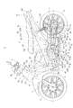
図1は、第1実施形態に係る自動二輪車の側面図を示している。
この自動二輪車1は、車体フレーム2と、車体フレーム2の前端に取り付けられたヘッドパイプ20により回動自在に支持された左右一対のフロントフォーク3と、フロントフォーク3の上端部に取り付けられた操舵用のハンドル4と、フロントフォーク3の下端部に回転自在に支持された前輪5と、車体の略中央で車体フレーム2に支持されたエンジン6と、車体フレーム2に上下に揺動自在に支持されたリヤフォーク7と、このリヤフォーク7の後端部に回転自在に支持された後輪8と、リヤフォーク7の後部と車体フレーム2との間に配設された左右のリヤクッション9と、車体フレーム2の後部上方に支持された燃料タンク10と、車体フレーム2に支持された収納ボックス11と、この収納ボックス11上に配置されたシート12と、シート12の後方に配置されたグラブレール13と、車体フレーム2を覆う合成樹脂製の車体カバー14とを備えている。
Hereinafter, an embodiment of the present invention will be described with reference to the accompanying drawings. In the description, descriptions of directions such as front and rear, left and right, and top and bottom are for the vehicle body.
<First Embodiment>
FIG. 1 is a side view of the motorcycle according to the first embodiment.
The
車体カバー14は、車体フレーム2の前部を覆うフロントカバー14Aと、運転者の足の前方を覆う左右一対のレッグシールド14Bと、エンジン6の前部を覆う左右一対のフロントサイドカバー14Cと、フロントサイドカバー14Cの上部間を連結するメインフレームトップカバー14Dと、収納ボックス11の下部を覆う左右一対のリアサイドカバー14Eと、収納ボックス11の残る部分及び燃料タンク10を両側から覆うリアボディカバー14Fとを備え、レッグシールド14Bとフロントサイドカバー14Cとメインフレームトップカバー14Dとが一体に形成されている。また、フロントカバー14Aには、ヘッドライト15及びウィンカ16が配設され、リアボディカバー14Fの後端にはテールランプ17が配設され、フロントフォーク3には前輪5を覆うフロントフェンダ18が配設されている。
The
車体フレーム2は、ヘッドパイプ20と、ヘッドパイプ20から車体中央を後下がりに延びるメインフレーム21と、メインフレーム21の後部に連結されて後上がりに延びる左右一対のリヤフレーム22と、各リヤフレーム22の前部に接合される左右一対のピボットプレート23と、各ピボットプレート23と各リヤフレーム22の中間部とをつなぐ左右一対の支持フレーム24とを備えている。リヤフレーム22には、収納ボックス11、燃料タンク10及び車体カバー14等が取り付けられ、収納ボックス11及び燃料タンク10を上方から覆い得るシート12が開閉自在に取り付けられている。また、リヤフレーム22の後部には、リヤクッションブラケット22Aを介してリヤクッション9の上部が連結されている。
The vehicle body frame 2 includes a
ピボットプレート23には、後輪8を支持するリヤフォーク7と、車体を直立した状態で停めるためのメインスタンド30と、車体を傾けた状態で停めるためのサイドスタンド31とが連結されている。リヤフォーク7は、その前端がピボットボルト7Aを介して両ピボットプレート23に回動自在に支持され、ピボットボルト7Aを支点に上下に揺動自在に支持されている。
The
メインスタンド30は、その一端がピボットボルト7Aより下方位置に挿通されたピボットシャフト34を介して両ピボットプレート23に回動自在に支持されている。このメインスタンド30は、図2に示すように、ピボットシャフト34が挿通される挿通部30Aと、この挿通部30Aから延びる左右一対の足部30Bと、一方の足部30B(本例では右側の足部)から車体中心側に延びるストッパ部30Cと、左側の足部30Bから延びる足掛け部30Dとを一体的に備えて構成され、ピボットシャフト34を支点として、足部30Bが図1に示す車体後方向きの位置(収納位置に相当)から車体下向きの位置(停車位置に相当)まで回動自在とされている。
One end of the
サイドスタンド31は、左側のピボットプレート23にボルト35を介して回動自在に支持され、図1においてはサイドスタンド31を出した状態を示している。なお、図1及び図2においては、シート12の前部に着座した運転者が足を乗せる左右一対のメインステップ36と、運転者が操作するチェンジペダル37及びブレーキペダル38と、シート12の後部に着座した同乗者が足を乗せる左右一対のピリオンステップ39とを示しており、ピリオンステップ39については車体側に折り畳んだ状態を示している。
The side stand 31 is rotatably supported on the
メインフレーム21の中間部両側には、図1に示すように、エンジンハンガ40が設けられ、エンジンハンガ40とピボットプレート23とを介してエンジン6が支持されている。エンジン6は、クランクケース41と、クランクケース41の前部に連結されるシリンダブロック42と、シリンダブロック42の前部に連結されるシリンダヘッド43と、シリンダヘッド43の前部に連結されるヘッドカバー44とを備え、シリンダブロック42内のシリンダが水平に配置された水平単気筒エンジン(水平エンジン)である。
As shown in FIG. 1,
このシリンダブロック42には、シリンダ42A内に往復自在にピストンが収容され、クランクケース41には、上記ピストンにコンロッドを介して連結されたクランク軸やエンジン6の出力軸6Aやキックペダル6Bが軸支されると共にクランク軸と出力軸6Aとの間の動力伝達機構を構成する遠心クラッチ機構や変速機構等が収容されている。上記出力軸6Aから後輪8への動力伝達は、チェーン伝動機構50を介して行われ、すなわち、上記出力軸6Aと後輪8とに各々設けられたスプロケット51、52と、これらスプロケット51、52に巻回されたドライブチェーン53を介してエンジン6の動力が後輪8に伝達される。
The
シリンダヘッド43は、シリンダ42A内に連通してシリンダヘッド43の上面に開口する吸気ポート43Aと、シリンダ42A内に連通してシリンダヘッド43の下面に開口する排気ポート43Bとを備えている。シリンダヘッド43とメインフレーム21との間には、エンジン6の吸気系を構成するスロットルボディ55とエアクリーナ56とが配設され、吸気ポート43Aにスロットルボディ55が接続され、スロットルボディ55の前部(上流側)にエアクリーナ56が接続されている。また、排気ポート43Bには、エンジン6の排気系を構成する排気ユニット60が接続されている。
The
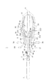
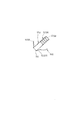
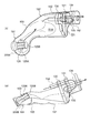
排気ユニット60は、図2に示すように、排気管61と触媒チャンバ80とマフラ90とを備え、排気管61は、排気ポート43Bとマフラ90とを結ぶ排気通路を構成している。図3(A)は排気管61と触媒チャンバ80を示す上面図であり、図3(B)はその側面図である。
As shown in FIG. 2, the
排気管61は、図3(A)(B)に示すように、屈曲管である前部排気管62と、略水平に延びる後部排気管63とを備え、前部排気管62は、図4及び図5に示すように、屈曲した金属管62Aの先端が拡径し、この拡径部より内側にジョイント64を備え、拡径部にカラー65を備えて構成されている。この前部排気管62は、図示せぬガスケットを間に挟んでカラー65をシリンダヘッド43に押し当て、ジョイント64をシリンダヘッド43にボルト留めすることによってシリンダヘッド43に連結されて排気ポート43Bに連通される。この前部排気管62は、図2及び図3(B)に示すように、エンジン6の幅内に収まるように、排気ポート43Bから延びてシリンダヘッド43近傍で屈曲して、その後端がシリンダヘッド43の下方で車体側方(右側方)に向けて開口し、この開口端に触媒チャンバ80が連結されている。後部排気管63は、触媒チャンバ80の後方で屈曲する屈曲部63Aが形成され、この屈曲部63Aによりエンジン6のクランクケース41の下方に締結されたドレンボルト6Dを避けて配置される。
As shown in FIGS. 3A and 3B, the
触媒チャンバ80は、図3(A)(B)に示すように、略円筒状の筒状ケース81を備え、この筒状ケース81は上下に二分割された上ケース81A及び下ケース81Bを上下合わせで溶接により接合して形成されている。この筒状ケース81は、側面から突出して開口する側面開口部82を備えている。この側面開口部82は、当該触媒チャンバ80の出入り口の一方の排気通路に対応し、この側面開口部82には、前部排気管62の後端が挿入されて溶接で接合され、この状態でエンジン6の排気ポート43Bに向かう開口となっている。
As shown in FIGS. 3 (A) and 3 (B), the
筒状ケース81の後端部には、縮径して開口する開口部83が設けられている。この開口部83は、当該触媒チャンバ80の出入り口の他方の排気通路に対応し、ケース内側から略円錐台形状のガイドキャップ84の小径部分が固定され、このガイドキャップ84の大径部分に触媒85が固定され、このガイドキャップ84の小径部分内側に後部排気管63が挿入されて溶接により接合されている。ガイドキャップ84を介して触媒85と後部排気管63とが同軸で配置されるため、触媒85が後部排気管63の排気通路の軸線に沿って配置されている。
また、筒状ケース81には、当該ケース81の上面及び下面(上ケース81A及び下ケース81B)を部分的にケース内側に凹ますことによって、上下一対の凹部81C、81Dが一体に形成され、これら凹部81C、81Dによって触媒85を上下から挟んで保持している。
At the rear end portion of the
The
触媒85は、排気ガス中の炭化水素と一酸化炭素と酸化窒素等を酸化、還元反応によって除去するものであり、この触媒85には、多孔質のハニカム構造体に白金、パラジウム、ロジウム等をコーティングして構成されたハニカム三元触媒が適用されている。この触媒85は、筒状ケース81の内壁(前壁及び側面壁)との間に所定の隙間を空けて保持され、上記側面開口部82が触媒85の長さ方向の幅内に開口して触媒85の側面に臨む位置に形成されている。
このため、エンジン6から排出された排気ガスは、前部排気管62を通って触媒チャンバ80内に入り、図3(A)に矢印で示すように、触媒85の側面に向かって流れた後、触媒85の周囲の隙間を通って触媒85内に入り、ここで炭化水素と一酸化炭素と酸化窒素等が酸化、還元反応によって除去された後、ガイドキャップ84を通って後部排気管63内に流れる。なお、ハニカム三元触媒に代えて、パンチングパイプに、白金、パラジウム、ロジウム等を担持させたヒートチューブを適用してもよい。
The
Therefore, after the exhaust gas discharged from the
本構成では、上記したように、触媒チャンバ80の側面開口部82には、排気ポート43Bから屈曲してシリンダヘッド43の下方で車体側方に開口する屈曲管である前部排気管62が連結されるため、触媒チャンバ80が、図1に示すように、シリンダ42Aの直下に近接して配置されることとなる。このため、触媒チャンバ80をシリンダヘッド43及びシリンダブロック42下方の空き空間に配置することができ、触媒チャンバ80によって車両の最低地上高が低くなってしまう事態や車両のバンク角度が制限されてしまう事態を回避することができる。
In this configuration, as described above, the
後部排気管63は、エンジン6の下方を車体中心を通って後方に延びた後、エンジン6の後方で車体斜め上方に屈曲し、その後端部にマフラ90が接続されている。この場合、後部排気管63が、エンジン6の幅内においてエンジン下方を通ってその後端でマフラ90に接続されるため、後部排気管63の曲げが小さく、排気抵抗を下げることができると共に、後部排気管63によって車両の最低地上高が低くなってしまう事態や車両のバンク角度が制限されてしまう事態を回避することができる。
The
マフラ90は、図1及び図2に示すように、筒状本体100を備え、この筒状本体100は、クランクケース41と後輪8との間に位置する第一マフラ部91と、後輪8の側方(右側方)に張り出すように延在して位置する第二マフラ部92と、これらマフラ部91、92を滑らかな曲線で一体に連結する連結部93とを備えて構成されている。
As shown in FIGS. 1 and 2, the
図6(A)はマフラ90の平面図であり、図6(B)はその側面図である。筒状本体100は、図6(A)(B)に示すように、上下に二分割されたケース100A、100Bを上下合わせで溶接して形成されている。
この筒状本体100の上ケース100Aには、当該ケース100Aの前後に各々ステー101、102が取り付けられ、これらステー101、102を介して筒状本体100が車体フレーム2に支持されている。また、下ケース100Bには、連結部93の下面に相当する位置に、ストッパ103が溶接により接合され、このストッパ103は、メインスタンド30が収納位置に回動した際にメインスタンド30のストッパ部30Cが当接してメインスタンド30のストッパとして機能する。
6A is a plan view of the
上述した構成では、マフラ90が、クランクケース41と後輪8との間に位置する第一マフラ部91と、後輪8の側方(右側方)に張り出して位置する第二マフラ部92と、これらマフラ部91、92を一体に連結する連結部93とを備えたため、マフラ90に必要な容量を、後輪8の前と横に分散させた形となり、クランクケース41と後輪8の間に同一容量のマフラを配置したものと比べると、ホイールベースを長くする必要がなく、車両の小型化が図られる。
In the configuration described above, the
図7(A)はマフラ90の下ケース100Bを周辺構成と共に示す平面図であり、図7(B)はその側面図である。下ケース100Bには、図7(A)(B)に示すように、前端壁100B1に前方斜め下方に開口する開口部110が設けられ、この開口部110には、図8に示すように、筒状の排気管連結管120が斜めに取り付けられ、この排気管連結管120には後部排気管63が連結され、これによって後部排気管63と排気管連結管120とが連通している。
この排気管連結管120は、図8に示すように、その周面に複数の開口孔120Aが形成されると共に、その後端の開口がプレート120B(図7(A)参照)で塞がれ、後部排気管63から排出された排気ガスを上記複数の開口孔120Aから排出させて第一マフラ部91のチャンバ(膨張室)R1内で膨張させ、チャンバ内の排気ガスを第二マフラ部92へ流す。
FIG. 7A is a plan view showing the
As shown in FIG. 8, the exhaust
第二マフラ部92は、第一隔壁130及び第二隔壁131を介して3つの膨張室(膨張室R1に連通する第一膨張室R1A、第二膨張室R2、第三膨張室R3)に仕切られ、第一隔壁130には、図7(A)に示すように、第一膨張室R1Aに連通する第一連通管132が貫通して固定され、この第一連通管132は、第三膨張室R3及び第二隔壁131を横断して第二膨張室R2に連通している。
第二隔壁131には、第一連通管132と干渉しない位置、より具体的には、第一連通管132より車体外側にずれた位置に、第二連通管133が貫通して固定され、この第二連通管133により第二膨張室R2と第三膨張室R3とが連通される。
The
The
さらに、第二隔壁131には、上記第一及び第二連通管132、133と干渉しない位置、つまり、第一連通管132より車体側にずれた位置に、第三膨張室R3に連通する第三連通管134が貫通して固定され、この第三連通管134は、第二膨張室R2を横断して下ケース100Bの後端壁100B2を貫通し、これにより、マフラ90内の排気ガスをマフラ90外に排出するテールパイプとして機能している。
この第三連通管134は、図7(B)に示すように、車体後方斜め下に傾くと共に、図7(A)に示すように、車体側方斜め下に傾く傾斜で第二隔壁131を貫通し、図9に示すように、下ケース100Bの後端壁100B2を貫通して第二隔壁131と後端壁100B2とに溶接により固定されている。これによって、テールパイプが車体に対して斜め下方、かつ斜め外側方に向けて配置され、排気の巻き込みが少なくなり、排気ガスによる車体後部の汚れを少なくすることができる。
Further, the
As shown in FIG. 7 (B), the
上記マフラ構造により、エンジン6から排出された排気ガスは、排気管61の途中に配置された触媒チャンバ80で浄化された後、マフラ90内に入り、図7(A)に矢印で示すように、第一マフラ部91の膨張室R1内に入った後、第二マフラ部92内の第一膨張室R1Aに入って第一連通管132を通って第二膨張室R2に入り、そこで流れる方向を反転して第二連通管133を通って第三膨張室R3に入った後、流れる方向を反転して第三連通管134を通ってマフラ90外に排出される。
このように、排気ガスを第一マフラ部91の膨張室R1で膨張させた後、第二マフラ部92内で排気ガスの流れを反転させて複数の膨張室R2、R3で膨張させるので、第一マフラ部91及び第二マフラ部92のマフラ容量を大きく確保することができ、排気音を十分に低減することができる。
Due to the muffler structure, the exhaust gas discharged from the
As described above, after the exhaust gas is expanded in the expansion chamber R1 of the
また、後輪8の側方に配置される第二マフラ部92の底形状は、図10〜図13に示すように、前後輪の接地点とメインステップ36の外側下端とを結ぶ車体右傾斜面L0に略沿って、車体体側(後輪8側)から車体右側方に向かって略斜め上方に傾斜する傾斜形状に形成されている。これによって、第二マフラ部92によって車両のバンク角度が制限されてしまう事態や車両の最低地上高が低くなってしまう事態を回避しつつ、第二マフラ部92の容量を十分に確保することができる。
Further, the bottom shape of the
本実施形態では、触媒チャンバ80の側面に、当該触媒チャンバ80の出入り口に対応した排気通路の一方を構成する側面開口部82を設けたので、排気ポート43Bから延びて屈曲する屈曲管である前部排気管62を上記側面開口部82に接続することができ、排気管の直線部分に触媒チャンバを配置するものに比して、触媒チャンバ80をコンパクトに配置することができ、また、触媒チャンバ80の配置自由度や排気管の設計自由度が向上する。これにより、本構成では、シリンダ42A下方のスペース、つまり、シリンダブロック42及びシリンダヘッド43の下方、かつ、クランクケース41より前方のスペースに、触媒チャンバ80をコンパクトに配置することができる。
In the present embodiment, since the side surface opening 82 constituting one of the exhaust passages corresponding to the entrance and exit of the
しかも、この触媒85の側面に上記側面開口部82を臨ませたので、触媒チャンバ80をシリンダヘッド43寄り(エンジン前寄り)に配置でき、シリンダ42A下方のスペースに触媒チャンバ80をレイアウトし易くなる。また、エンジン6からの排気ガスが触媒85の周囲を回り込んで触媒85を通過するため、触媒85を通過する排気ガスの流速を抑えることができる。さらに、触媒85を後部排気管63の排気通路の軸線に沿って配置したので、触媒チャンバ80を小型化することが可能である。
In addition, since the
また、触媒チャンバ80の側面開口部82を排気ポート43Bに向かう開口としたので、排気ポート43Bからの高熱の排気ガスの熱により触媒85の温度が活性化温度に達しやすくなり、冷機時であっても、エンジン6の始動直後から比較的短時間の内に触媒85を活性化させることができ、かつ、この側面開口部82には外部からの水が侵入し難く、触媒85の被水を防ぐことができる。
また、本構成では、触媒チャンバ80の筒状ケース81の上下を凹ませて凹部81C、81Dを形成し、これら凹部81C、81Dによって触媒85を保持したので、触媒85を固定する別の固定部材を必要とせず、製作コストを低減することができる。しかも、触媒チャンバ80を2つのケース81A、81Bを上下合わせで接合して形成したので、ケース81A、81Bを接合すれば触媒85を保持でき、触媒85の組み付けを容易に行うことができる。
Further, since the side surface opening 82 of the
Further, in this configuration, the
また、本実施形態では、マフラ90が、エンジン6と後輪8との間に位置する第一マフラ部91と、後輪8の側方(右側方)に張り出して位置する第二マフラ部92と、これらマフラ部91、92を一体に連結する連結部93とを備えたため、マフラ90に必要な容量を後輪8の前と横に分散させた形となり、ホイールベースを長くする必要がなく、車両の小型化が図られる。
しかも、後部排気管63が、車体中心下方を通ってエンジン6の後方で車体斜め上方に屈曲して第一マフラ部91に接続されるので、排気管の曲げが大きくならず、排気管の加工や精度の確保が容易となり、かつ、排気抵抗が低減される。
In the present embodiment, the
In addition, since the
また、上記マフラ90を上ケース100Aと下ケース100Bの上下合わせで形成したので、マフラ90の製造や組み立てが容易となり、生産性が向上する。また、後部排気管63が、第一マフラ部91の接続部に対し、前方下方から斜め上向きに挿入されるので、後部排気管63の曲げが大きくならず、排気抵抗を低減できると共に、後部排気管63を第一マフラ部91における上下ケース100A、100Bの溶接ビード(つなぎ目)に干渉しない位置に連結することができる。
また、第一マフラ部91と第二マフラ部92とを連結する連結部93にメインスタンド30のストッパ103を配置したので、このストッパ103が上記マフラ部91、92の連結を補強する補強部材を兼ねることができる。
また、テールパイプが車体に対して斜め下方、かつ斜め外側方に向けて第二マフラ部92に配置されるので、排気の巻き込みが少なくなり、排気ガスによる車体後部の汚れを少なくすることができる。
Moreover, since the
In addition, since the
Further, since the tail pipe is disposed in the
<第2実施形態>
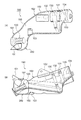
図14は、第2実施形態に係る触媒チャンバ180をエンジン6と共に示す側面図である。また、図15(A)は排気管161と触媒チャンバ180の平面図であり、図15(B)はその側面図であり、図16は前方から見た図であり、図17は縦断面図である。なお、第1実施形態と同様の構成は同一の符号を付して重複する説明は省略する。
図14に示すように、エンジン6は、クランクケース41と、クランクケース41の前部に連結されるシリンダブロック42と、シリンダブロック42の前部に連結されるシリンダヘッド43と、シリンダヘッド43の前部に連結されるヘッドカバー44とを備え、シリンダブロック42内のシリンダが水平に配置された水平単気筒エンジン(水平エンジン)である。
Second Embodiment
FIG. 14 is a side view showing the
As shown in FIG. 14, the
エンジン6の排気系を構成する排気ユニット60は、排気管161と触媒チャンバ180と後述するマフラ190とを備えている。排気管161は、エンジン6と触媒チャンバ180とを接続する前部排気管162と、触媒チャンバ180とマフラ90とを接続する後部排気管163とを備えている。
前部排気管162は、エンジン6の幅内に収まるように屈曲する屈曲管であり、より具体的には、図14及び図16に示すように、シリンダヘッド43の排気口から触媒チャンバ180の前側右側方を下方へ延び、この触媒チャンバ180の左側方に向かって回り込むように屈曲しながら後方へ延び、シリンダブロック42の下方で車体側方(右側方)に向けて開口し、この開口端に触媒チャンバ80が連結されている。
The
The
後部排気管163は、図14に示すように、触媒チャンバ80の後端からクランクケース41の下方を後方へ延びる。この後部排気管163は、図15(B)に示すように、その断面形状が、真円形状から横長の楕円形状へと変化した後、再び真円形状に戻る形状に形成され、かつ、これら断面形状は略同じ断面積に形成されている。
このように後部排気管163の断面形状を変化させたのは以下の理由による。
図14に示すように、クランクケース41の下面は、側面視で、シリンダブロック42との接続部から後ろ下がりに傾斜する前部傾斜面41Aと、この前部傾斜面41Cの下端から後方へ略水平に延びる水平面41Bと、この水平面41Bの後端から後ろ上がりに傾斜する後部傾斜面41Cとを有している。この構成の下では、後部排気管163全体を真円形状にした場合、後部排気管163の断面積を十分に確保しようとすると、クランクケース41の最下面である水平面41Bの下方で後部排気管163が目的とする最低地上高より低い位置に配置されてしまう場合があった。
As shown in FIG. 14, the
The reason why the cross-sectional shape of the
As shown in FIG. 14, the lower surface of the
そこで、本実施形態の後部排気管163では、前部傾斜面41A、水平面41B及び後部傾斜面41Cの傾斜に沿って、つまり、クランクケース41の下面の傾斜に沿って高さ(車体上下方向の径)が変化するように、略同じ断面積の真円形状から横長の楕円形状へと変化した後、再び真円形状に戻る形状にすることにより、後部排気管163の排気抵抗を略均一に維持しつつ、十分な最低地上高を確保することができる。
Therefore, in the
続いて、触媒チャンバ180について詳述する。触媒チャンバ180は、図14に示すように、エンジン6のシリンダブロック42及びクランクケース41の下方に配置され、触媒85を収容する触媒収容部180Aと、この触媒収容部180Aからシリンダブロック42とクランクケース41とに沿うようにエンジン6側(車体上側)に膨出する膨出部180Bとを備えている。
この触媒チャンバ180は、図15(A)(B)に示すように、触媒収容部180Aと膨出部180Bとを一体に形成する筒状ケース181を備え、この筒状ケース181は、略お椀状に形成された左ケース181Aと右ケース181Bとを互いに接合することにより形成されている。
Next, the
As shown in FIGS. 15A and 15B, the
筒状ケース181の膨出部180Bの側面、つまり、左ケース181Aの側面上部には、図16に示すように、車体幅方向(車体左方向)に向けて開口する側面開口部182が形成されている。この側面開口部182は、当該触媒チャンバ80の出入り口の一方の排気通路に対応し、この側面開口部182には、前部排気管162の後端が挿入されて溶接で接合される。
A
筒状ケース181の触媒収容部180Aの後端部には、図17に示すように、後方に向けて開口する開口部183が設けられている。この開口部183は、触媒チャンバ80の出入り口の他方の排気通路に対応し、この開口部183には、後部排気管63がその前端部分をケース181内に挿入した状態で溶接により接合され、ケース181内側からその前端部分に触媒85が固定される。これにより、後部排気管163の通路方向に触媒85の軸心が合って触媒85と後部排気管63とが同軸で配置され、触媒85が後部排気管163の排気通路の軸線に沿って配置されると共に、前部排気管162を触媒85の長さ方向の幅内に開口させることができる。
As shown in FIG. 17, an
ところで、エンジンからの排気ガスが触媒チャンバ内の触媒に向けて排出される構成の場合には触媒等が振動するおそれがあった。
これに対し、本実施形態では、上述したように、触媒チャンバ180の触媒収容部180Aから膨出する膨出部180Bを設け、この膨出部180Bの側面開口部182に前部排気管162を接続したので、エンジン6からの排気通路を触媒85からオフセットした位置に通じるように構成されている。
By the way, when the exhaust gas from the engine is discharged toward the catalyst in the catalyst chamber, the catalyst or the like may vibrate.
In contrast, in the present embodiment, as described above, the bulging
このため、エンジン6からの排気ガスは、図16に波線矢印Gで示すように、触媒85に向けて排出されるのではなく、触媒チャンバ180の膨出部180Bの内壁180B1に向かって排出され、この内壁180B1に当たった後に触媒85に向けて流れて触媒85を通過する。従って、排気ガスは、内壁180B1に当たることによりその流速を下げると共に、膨出部180B内で膨張することによっても流速を下げ、その後に触媒85を通過するので、触媒85を通過する排気ガスの流速を確実に抑えることができ、上述した振動を回避することができる。
Therefore, the exhaust gas from the
図18(A)はマフラ190の平面図であり、図18(B)はその側面図を示している。マフラ190は、上下に二分割されたケース200A、200Bを上下合わせで接合した筒状本体200を備えている。この筒状本体200は、クランクケース41と後輪8との間に位置する第一マフラ部191と、後輪8の側方(右側方)に張り出すように延在して位置する第二マフラ部192と、これらマフラ部191、192を滑らかな曲線で一体に連結する連結部193とを備えて構成されている。
このマフラ190は、第1実施形態と同様に、このマフラ190に必要な容量を後輪8の前と横に分散させた形になるので、クランクケース41と後輪8との間に同一容量のマフラを配置したものと比べ、ホイールベースを長くする必要がなく、車両の小型化が可能となる。
18A is a plan view of the
Similar to the first embodiment, the
図19(A)はマフラ190の下ケース200Bを周辺構成と共に示す平面図であり、図19(B)はその側面図である。下ケース200Bの前部には、前方斜め下方に開口するように筒状の排気管連結管120が取り付けられる。この排気管連結管120には、後部排気管163が連結され、後部排気管163から排出された排気ガスを複数の開口孔120Aから排出させて第一マフラ部191の膨張室(チャンバ)R1内で膨張させ、膨張室R1内の排気ガスを第二マフラ部192へ流す。
第二マフラ部192は、第一隔壁130及び第二隔壁131を介して3つの膨張室(膨張室R1に連通する第一膨張室R1A、第二膨張室R2、第三膨張室R3)に仕切られ、各膨張室R1A、R2、R3には、第一連通管132、第二連通管133及びテールパイプを兼用する第三連通管134が固定される。
FIG. 19A is a plan view showing the
The
上記マフラ構造により、エンジン6から排出された排気ガスは、触媒チャンバ180で浄化された後、マフラ190内に入り、図19(A)(B)に矢印で示すように、第一マフラ部191の膨張室R1内に入った後、第二マフラ部192内の第一膨張室R1Aに入って第一連通管132を通って第二膨張室R2に入り、そこで流れる方向を反転して第二連通管133を通って第三膨張室R3に入った後、流れる方向を反転して第三連通管134を通ってマフラ190外に排出される。
本実施形態では、図19(A)(B)に示すように、第二隔壁131に固定される複数(本例では3本)の連通管132、133、134を縦並びに配置しているので、これら連通管132、133、134の配置スペースを幅狭にすることができ、マフラ190の形状自由度を向上させることができる。
Due to the muffler structure, the exhaust gas discharged from the
In this embodiment, as shown in FIGS. 19A and 19B, a plurality (three in this example) of
この実施形態では、触媒チャンバ180の膨出部180Bの側面に、一方の排気通路に対応する前部排気管162を接続したので、第1実施形態の効果に加えて、エンジン6からの排気通路が触媒チャンバ180における触媒85からオフセットした位置に通じ、排気ガスを触媒チャンバ180内でその流速を下げた後に触媒85を通過させることができる。これにより、触媒85等の振動を防止することができる。
In this embodiment, since the
しかも、上記膨出部180Bが、シリンダブロック42とクランクケース41とに沿うようにエンジン6側に膨出するので、シリンダブロック42とクランクケース41との間のデッドペースに膨出部180Bをレイアウトでき、レイアウト効率を高めることができる。また、前部排気管162が、触媒チャンバ180の周囲を回り込んで触媒チャンバ180につながるので、排気ガスの流れをスムーズにすることができる。
Moreover, since the bulging
以上、一実施形態に基づいて本発明を説明したが、本発明はこれに限定されるものでないことは明らかである。例えば、触媒チャンバ80、180をパイプ加工品としてもよい。また、上述の各実施形態では、エンジン6からの排気ガスを触媒チャンバ80の側面開口部82、182から入れて、触媒チャンバ80、180内の触媒85を通過させて後端の開口部83、183から排出させる場合を説明したが、排気の流れを逆方向としてもよく、すなわち、エンジン6の排気ガスを触媒チャンバ80、180の開口部83、183から入れて触媒85を通過させ、側面開口部82から排出させるようにしてよい。
また、上述の実施形態では、シリンダが水平に配置された水平単気筒エンジンを搭載する自動二輪車に本発明を適用する場合を説明したが、これに限らず、シリンダが直立した直立エンジンや多気筒エンジンを搭載する自動二輪車に広く適用することができる。
As mentioned above, although this invention was demonstrated based on one Embodiment, it is clear that this invention is not limited to this. For example, the
In the above-described embodiment, the case where the present invention is applied to a motorcycle equipped with a horizontal single-cylinder engine in which cylinders are horizontally arranged has been described. It can be widely applied to motorcycles equipped with engines.
1 自動二輪車
2 車体フレーム
6 エンジン(水平エンジン)
30 メインスタンド
31 サイドスタンド
42A シリンダ
43A 吸気ポート
43B 排気ポート
60 排気ユニット
61、161 排気管
62、162 前部排気管
63、163 後部排気管
80、180 触媒チャンバ
82、182 側面開口部
83、183 開口部
85 触媒
90、190 マフラ
91、191 第一マフラ部
92、192 第二マフラ部
93、193 連結部
103 ストッパ
180A 触媒収容部
180B 膨出部
L0 車体右傾斜面
R1、R1A、R2、R3 膨張室
1 Motorcycle 2
30 Main stand 31 Side stand
Claims (6)
前記水平エンジン(6)のクランクケース(41)が、前記シリンダ(42A)の後方に配置されるとともに、シリンダ下端より下方に膨出するように形成され、前記触媒チャンバ(80,180)は前記クランクケース(41)の前方、かつ、シリンダ下方に配置され、
前記触媒チャンバ(80,180)の出入り口に対応した排気通路のうち、前記マフラ(90,190)に向かう一方の排気通路(83,183)の通路方向に触媒(85)の軸心を合わせ、前記排気ポート(43B)に向かう他方の排気通路(82,182)を前記触媒(85)の長さ方向の幅内に開口させ、
前記触媒チャンバ(80,180)の前端位置が、前記他方の排気通路(82,182)が前記触媒チャンバ(80,180)の側面に開口する位置より前方に形成されることを特徴とする自動二輪車の触媒配置構造。 In the horizontal engine (6) in which the cylinder (42A) is horizontally disposed , the catalyst chamber (80 ) is placed in the middle of the exhaust pipe (61, 161) connecting the exhaust port (43B) of the cylinder head (43 ) and the muffler (90, 190). , 180) in the catalyst arrangement structure of the motorcycle,
A crankcase (41) of the horizontal engine (6) is disposed at the rear of the cylinder (42A) and is formed so as to bulge downward from the lower end of the cylinder. The catalyst chamber (80, 180) is Arranged in front of the crankcase (41) and below the cylinder,
Of the exhaust passages corresponding to the entrances and exits of the catalyst chamber (80, 180) , the axis of the catalyst (85) is aligned with the passage direction of one exhaust passage (83, 183) toward the muffler (90, 190) , wherein the exhaust passage of the other towards the exhaust port (43B) (82 and 182) is opened within the width in the longitudinal direction of the catalyst (85),
A front end position of the catalyst chamber (80, 180) is formed in front of a position where the other exhaust passage (82, 182) opens in a side surface of the catalyst chamber (80, 180). The catalyst arrangement structure of a motorcycle.
前記一方の排気通路(83,183)の軸心に沿って前記触媒(85)を配置し、この触媒(85)の軸心方向に沿って延び前記マフラ(90,190)に連なる後部排気管(63,163)を接続し、前記他方の排気通路(82,182)を前記隙間に開口させ、当該開口に前記排気ポート(43B)に連なる前部排気管(62,162)を接続したことを特徴とする請求項1に記載の自動二輪車の触媒配置構造。 The catalyst (85) is disposed along the axial center of the one exhaust passage (83, 183), and extends along the axial direction of the catalyst (85), and is connected to the muffler (90, 190). (63, 163) is connected, the other exhaust passage (82, 182) is opened in the gap, and the front exhaust pipe (62, 162) connected to the exhaust port (43B) is connected to the opening. The catalyst arrangement structure for a motorcycle according to claim 1.
Priority Applications (9)
| Application Number | Priority Date | Filing Date | Title |
|---|---|---|---|
| JP2006259959A JP4693733B2 (en) | 2006-05-31 | 2006-09-26 | Catalyst arrangement structure for motorcycles |
| TW096113361A TW200745445A (en) | 2006-05-31 | 2007-04-16 | Structure for arrangement of catalyst for motorcycle |
| KR1020070049745A KR100864769B1 (en) | 2006-05-31 | 2007-05-22 | Structure for arrangement of catalyst for motorcycle |
| BRPI0702557-2A BRPI0702557B1 (en) | 2006-05-31 | 2007-05-25 | STRUCTURE OF CATALYST DISPOSAL OF A MOTORCYCLE |
| CN2007101042995A CN101082296B (en) | 2006-05-31 | 2007-05-25 | Catalyst configuration structure of locomotive two-wheeled vehicle |
| PE2007000662A PE20080616A1 (en) | 2006-05-31 | 2007-05-28 | A CATALYST ARRANGEMENT STRUCTURE OF A MOTORCYCLE |
| MYPI20070839A MY145188A (en) | 2006-05-31 | 2007-05-28 | A catalyst arrangement structure of motorcycle |
| MX2007006344A MX2007006344A (en) | 2006-05-31 | 2007-05-29 | Catalyst arrangement structure for motorcycle . |
| ARP070102291A AR060969A1 (en) | 2006-05-31 | 2007-05-29 | A CATALYST DISPOSAL STRUCTURE OF A MOTORCYCLE |
Applications Claiming Priority (3)
| Application Number | Priority Date | Filing Date | Title |
|---|---|---|---|
| JP2006152619 | 2006-05-31 | ||
| JP2006152619 | 2006-05-31 | ||
| JP2006259959A JP4693733B2 (en) | 2006-05-31 | 2006-09-26 | Catalyst arrangement structure for motorcycles |
Publications (2)
| Publication Number | Publication Date |
|---|---|
| JP2008008279A JP2008008279A (en) | 2008-01-17 |
| JP4693733B2 true JP4693733B2 (en) | 2011-06-01 |
Family
ID=39066697
Family Applications (1)
| Application Number | Title | Priority Date | Filing Date |
|---|---|---|---|
| JP2006259959A Expired - Fee Related JP4693733B2 (en) | 2006-05-31 | 2006-09-26 | Catalyst arrangement structure for motorcycles |
Country Status (9)
| Country | Link |
|---|---|
| JP (1) | JP4693733B2 (en) |
| KR (1) | KR100864769B1 (en) |
| CN (1) | CN101082296B (en) |
| AR (1) | AR060969A1 (en) |
| BR (1) | BRPI0702557B1 (en) |
| MX (1) | MX2007006344A (en) |
| MY (1) | MY145188A (en) |
| PE (1) | PE20080616A1 (en) |
| TW (1) | TW200745445A (en) |
Families Citing this family (6)
| Publication number | Priority date | Publication date | Assignee | Title |
|---|---|---|---|---|
| JP2011007137A (en) * | 2009-06-26 | 2011-01-13 | Suzuki Motor Corp | Muffler and motorcycle |
| JP5930944B2 (en) * | 2012-11-09 | 2016-06-08 | 本田技研工業株式会社 | Saddle riding |
| WO2016104160A1 (en) * | 2014-12-22 | 2016-06-30 | ヤマハ発動機株式会社 | Air-cooled engine unit |
| EP3239504B1 (en) * | 2014-12-22 | 2019-02-27 | Yamaha Hatsudoki Kabushiki Kaisha | Engine unit |
| WO2018030110A1 (en) * | 2016-08-10 | 2018-02-15 | 本田技研工業株式会社 | Exhaust structure for saddled vehicle |
| DE112018004342T5 (en) * | 2017-09-21 | 2020-05-07 | Honda Motor Co., Ltd. | SADDLE VEHICLE |
Citations (7)
| Publication number | Priority date | Publication date | Assignee | Title |
|---|---|---|---|---|
| JPS56135709A (en) * | 1980-03-26 | 1981-10-23 | Yamaha Motor Co Ltd | Exhaust gas purifier for motor bicycle |
| JPH0419613U (en) * | 1990-06-05 | 1992-02-19 | ||
| JPH04501753A (en) * | 1988-10-11 | 1992-03-26 | エミテツク ゲゼルシヤフト フユア エミツシオンス テクノロギー ミツト ベシユレンクテル ハフツング | Catalyst with double cover device |
| JP2000110661A (en) * | 1998-10-05 | 2000-04-18 | Honda Motor Co Ltd | Horizontally opposed type engine for motocycle |
| JP2000335467A (en) * | 1999-05-28 | 2000-12-05 | Honda Motor Co Ltd | Exhaust gas sensor in motorcycle |
| JP2002317627A (en) * | 2001-04-20 | 2002-10-31 | Suzuki Motor Corp | Exhaust emission control device |
| JP2004332607A (en) * | 2003-05-07 | 2004-11-25 | Sango Co Ltd | Exhaust emission control device for internal combustion engine |
Family Cites Families (4)
| Publication number | Priority date | Publication date | Assignee | Title |
|---|---|---|---|---|
| TW384349B (en) * | 1998-01-14 | 2000-03-11 | Emitec Emissionstechnologie | Catalytic converter for a muffler of a small engine |
| JP3525854B2 (en) | 2000-03-28 | 2004-05-10 | トヨタ自動車株式会社 | Exhaust gas purification device for internal combustion engine |
| JP2003000131A (en) * | 2001-06-25 | 2003-01-07 | Shimada Shoji Kk | Capturing device for rats |
| JP2004116322A (en) * | 2002-09-24 | 2004-04-15 | Mitsubishi Fuso Truck & Bus Corp | Exhaust gas posttreatment device of internal combustion engine |
-
2006
- 2006-09-26 JP JP2006259959A patent/JP4693733B2/en not_active Expired - Fee Related
-
2007
- 2007-04-16 TW TW096113361A patent/TW200745445A/en not_active IP Right Cessation
- 2007-05-22 KR KR1020070049745A patent/KR100864769B1/en active IP Right Grant
- 2007-05-25 CN CN2007101042995A patent/CN101082296B/en not_active Expired - Fee Related
- 2007-05-25 BR BRPI0702557-2A patent/BRPI0702557B1/en active IP Right Grant
- 2007-05-28 MY MYPI20070839A patent/MY145188A/en unknown
- 2007-05-28 PE PE2007000662A patent/PE20080616A1/en not_active Application Discontinuation
- 2007-05-29 MX MX2007006344A patent/MX2007006344A/en active IP Right Grant
- 2007-05-29 AR ARP070102291A patent/AR060969A1/en active IP Right Grant
Patent Citations (7)
| Publication number | Priority date | Publication date | Assignee | Title |
|---|---|---|---|---|
| JPS56135709A (en) * | 1980-03-26 | 1981-10-23 | Yamaha Motor Co Ltd | Exhaust gas purifier for motor bicycle |
| JPH04501753A (en) * | 1988-10-11 | 1992-03-26 | エミテツク ゲゼルシヤフト フユア エミツシオンス テクノロギー ミツト ベシユレンクテル ハフツング | Catalyst with double cover device |
| JPH0419613U (en) * | 1990-06-05 | 1992-02-19 | ||
| JP2000110661A (en) * | 1998-10-05 | 2000-04-18 | Honda Motor Co Ltd | Horizontally opposed type engine for motocycle |
| JP2000335467A (en) * | 1999-05-28 | 2000-12-05 | Honda Motor Co Ltd | Exhaust gas sensor in motorcycle |
| JP2002317627A (en) * | 2001-04-20 | 2002-10-31 | Suzuki Motor Corp | Exhaust emission control device |
| JP2004332607A (en) * | 2003-05-07 | 2004-11-25 | Sango Co Ltd | Exhaust emission control device for internal combustion engine |
Also Published As
| Publication number | Publication date |
|---|---|
| TW200745445A (en) | 2007-12-16 |
| AR060969A1 (en) | 2008-07-23 |
| KR20070115634A (en) | 2007-12-06 |
| PE20080616A1 (en) | 2008-07-01 |
| BRPI0702557A (en) | 2008-02-19 |
| KR100864769B1 (en) | 2008-10-22 |
| TWI332544B (en) | 2010-11-01 |
| CN101082296A (en) | 2007-12-05 |
| BRPI0702557B1 (en) | 2020-09-15 |
| JP2008008279A (en) | 2008-01-17 |
| CN101082296B (en) | 2011-03-09 |
| MX2007006344A (en) | 2008-12-12 |
| MY145188A (en) | 2011-12-30 |
Similar Documents
| Publication | Publication Date | Title |
|---|---|---|
| JP4648790B2 (en) | Exhaust device for small vehicles | |
| US7699134B2 (en) | Motorcycle exhaust system | |
| TWI309691B (en) | ||
| US8042649B2 (en) | Vehicular muffler and motorcycle incorporating same | |
| JP4693733B2 (en) | Catalyst arrangement structure for motorcycles | |
| JP2014047762A (en) | Two-wheeled motor vehicle | |
| EP3059407B1 (en) | Exhaust muffler | |
| JPWO2005080764A1 (en) | Engine exhaust gas purification device | |
| JP2017150311A (en) | Engine unit and ride type vehicle | |
| CN100400812C (en) | Exhaust gas purification device | |
| JP2019183673A (en) | Arrangement structure of exhaust gas sensor | |
| JP2006009648A (en) | Exhaust emission control device for motorcycle | |
| JP2017150309A (en) | Engine unit and ride type vehicle | |
| JP4693695B2 (en) | Motorcycle muffler structure | |
| JP2020133477A (en) | Exhaust muffler structure | |
| JP2006327586A5 (en) | ||
| CN112567114B (en) | Exhaust system | |
| WO2023053996A1 (en) | Saddle-type vehicle | |
| JP6130262B2 (en) | Motorcycle exhaust system | |
| JP2019210864A (en) | Tail pipe structure of saddle riding type vehicle | |
| JP7275775B2 (en) | motorcycle | |
| JP7157110B2 (en) | Straddle type vehicle exhaust structure | |
| JP5831186B2 (en) | Silencers and motorcycles for internal combustion engines | |
| JP7352416B2 (en) | Exhaust system for saddle type vehicles | |
| JP7172290B2 (en) | motorcycle |
Legal Events
| Date | Code | Title | Description |
|---|---|---|---|
| A621 | Written request for application examination |
Free format text: JAPANESE INTERMEDIATE CODE: A621 Effective date: 20081126 |
|
| A131 | Notification of reasons for refusal |
Free format text: JAPANESE INTERMEDIATE CODE: A131 Effective date: 20100914 |
|
| A977 | Report on retrieval |
Free format text: JAPANESE INTERMEDIATE CODE: A971007 Effective date: 20100916 |
|
| A521 | Written amendment |
Free format text: JAPANESE INTERMEDIATE CODE: A523 Effective date: 20101110 |
|
| RD02 | Notification of acceptance of power of attorney |
Free format text: JAPANESE INTERMEDIATE CODE: A7422 Effective date: 20101110 |
|
| TRDD | Decision of grant or rejection written | ||
| A01 | Written decision to grant a patent or to grant a registration (utility model) |
Free format text: JAPANESE INTERMEDIATE CODE: A01 Effective date: 20110208 |
|
| A01 | Written decision to grant a patent or to grant a registration (utility model) |
Free format text: JAPANESE INTERMEDIATE CODE: A01 |
|
| A61 | First payment of annual fees (during grant procedure) |
Free format text: JAPANESE INTERMEDIATE CODE: A61 Effective date: 20110222 |
|
| FPAY | Renewal fee payment (event date is renewal date of database) |
Free format text: PAYMENT UNTIL: 20140304 Year of fee payment: 3 |
|
| R150 | Certificate of patent or registration of utility model |
Ref document number: 4693733 Country of ref document: JP Free format text: JAPANESE INTERMEDIATE CODE: R150 Free format text: JAPANESE INTERMEDIATE CODE: R150 |
|
| LAPS | Cancellation because of no payment of annual fees |