JP4679212B2 - High temperature reformer - Google Patents
High temperature reformer Download PDFInfo
- Publication number
- JP4679212B2 JP4679212B2 JP2005112080A JP2005112080A JP4679212B2 JP 4679212 B2 JP4679212 B2 JP 4679212B2 JP 2005112080 A JP2005112080 A JP 2005112080A JP 2005112080 A JP2005112080 A JP 2005112080A JP 4679212 B2 JP4679212 B2 JP 4679212B2
- Authority
- JP
- Japan
- Prior art keywords
- reaction chamber
- gas
- oxidation reaction
- reduction reaction
- gasification reactor
- Prior art date
- Legal status (The legal status is an assumption and is not a legal conclusion. Google has not performed a legal analysis and makes no representation as to the accuracy of the status listed.)
- Expired - Fee Related
Links
Images


Classifications
-
- B—PERFORMING OPERATIONS; TRANSPORTING
- B67—OPENING, CLOSING OR CLEANING BOTTLES, JARS OR SIMILAR CONTAINERS; LIQUID HANDLING
- B67D—DISPENSING, DELIVERING OR TRANSFERRING LIQUIDS, NOT OTHERWISE PROVIDED FOR
- B67D1/00—Apparatus or devices for dispensing beverages on draught
- B67D1/08—Details
- B67D1/0857—Cooling arrangements
-
- C—CHEMISTRY; METALLURGY
- C10—PETROLEUM, GAS OR COKE INDUSTRIES; TECHNICAL GASES CONTAINING CARBON MONOXIDE; FUELS; LUBRICANTS; PEAT
- C10J—PRODUCTION OF PRODUCER GAS, WATER-GAS, SYNTHESIS GAS FROM SOLID CARBONACEOUS MATERIAL, OR MIXTURES CONTAINING THESE GASES; CARBURETTING AIR OR OTHER GASES
- C10J3/00—Production of combustible gases containing carbon monoxide from solid carbonaceous fuels
- C10J3/46—Gasification of granular or pulverulent flues in suspension
- C10J3/48—Apparatus; Plants
- C10J3/485—Entrained flow gasifiers
-
- B—PERFORMING OPERATIONS; TRANSPORTING
- B67—OPENING, CLOSING OR CLEANING BOTTLES, JARS OR SIMILAR CONTAINERS; LIQUID HANDLING
- B67D—DISPENSING, DELIVERING OR TRANSFERRING LIQUIDS, NOT OTHERWISE PROVIDED FOR
- B67D1/00—Apparatus or devices for dispensing beverages on draught
- B67D1/08—Details
- B67D1/12—Flow or pressure control devices or systems, e.g. valves, gas pressure control, level control in storage containers
-
- C—CHEMISTRY; METALLURGY
- C01—INORGANIC CHEMISTRY
- C01B—NON-METALLIC ELEMENTS; COMPOUNDS THEREOF; METALLOIDS OR COMPOUNDS THEREOF NOT COVERED BY SUBCLASS C01C
- C01B3/00—Hydrogen; Gaseous mixtures containing hydrogen; Separation of hydrogen from mixtures containing it; Purification of hydrogen
- C01B3/02—Production of hydrogen or of gaseous mixtures containing a substantial proportion of hydrogen
- C01B3/32—Production of hydrogen or of gaseous mixtures containing a substantial proportion of hydrogen by reaction of gaseous or liquid organic compounds with gasifying agents, e.g. water, carbon dioxide, air
-
- C—CHEMISTRY; METALLURGY
- C02—TREATMENT OF WATER, WASTE WATER, SEWAGE, OR SLUDGE
- C02F—TREATMENT OF WATER, WASTE WATER, SEWAGE, OR SLUDGE
- C02F1/00—Treatment of water, waste water, or sewage
- C02F1/42—Treatment of water, waste water, or sewage by ion-exchange
-
- C—CHEMISTRY; METALLURGY
- C10—PETROLEUM, GAS OR COKE INDUSTRIES; TECHNICAL GASES CONTAINING CARBON MONOXIDE; FUELS; LUBRICANTS; PEAT
- C10J—PRODUCTION OF PRODUCER GAS, WATER-GAS, SYNTHESIS GAS FROM SOLID CARBONACEOUS MATERIAL, OR MIXTURES CONTAINING THESE GASES; CARBURETTING AIR OR OTHER GASES
- C10J3/00—Production of combustible gases containing carbon monoxide from solid carbonaceous fuels
- C10J3/46—Gasification of granular or pulverulent flues in suspension
- C10J3/48—Apparatus; Plants
- C10J3/482—Gasifiers with stationary fluidised bed
-
- C—CHEMISTRY; METALLURGY
- C10—PETROLEUM, GAS OR COKE INDUSTRIES; TECHNICAL GASES CONTAINING CARBON MONOXIDE; FUELS; LUBRICANTS; PEAT
- C10J—PRODUCTION OF PRODUCER GAS, WATER-GAS, SYNTHESIS GAS FROM SOLID CARBONACEOUS MATERIAL, OR MIXTURES CONTAINING THESE GASES; CARBURETTING AIR OR OTHER GASES
- C10J3/00—Production of combustible gases containing carbon monoxide from solid carbonaceous fuels
- C10J3/72—Other features
- C10J3/723—Controlling or regulating the gasification process
-
- C—CHEMISTRY; METALLURGY
- C10—PETROLEUM, GAS OR COKE INDUSTRIES; TECHNICAL GASES CONTAINING CARBON MONOXIDE; FUELS; LUBRICANTS; PEAT
- C10J—PRODUCTION OF PRODUCER GAS, WATER-GAS, SYNTHESIS GAS FROM SOLID CARBONACEOUS MATERIAL, OR MIXTURES CONTAINING THESE GASES; CARBURETTING AIR OR OTHER GASES
- C10J3/00—Production of combustible gases containing carbon monoxide from solid carbonaceous fuels
- C10J3/72—Other features
- C10J3/80—Other features with arrangements for preheating the blast or the water vapour
-
- C—CHEMISTRY; METALLURGY
- C01—INORGANIC CHEMISTRY
- C01B—NON-METALLIC ELEMENTS; COMPOUNDS THEREOF; METALLOIDS OR COMPOUNDS THEREOF NOT COVERED BY SUBCLASS C01C
- C01B2203/00—Integrated processes for the production of hydrogen or synthesis gas
- C01B2203/02—Processes for making hydrogen or synthesis gas
- C01B2203/0205—Processes for making hydrogen or synthesis gas containing a reforming step
- C01B2203/0211—Processes for making hydrogen or synthesis gas containing a reforming step containing a non-catalytic reforming step
- C01B2203/0216—Processes for making hydrogen or synthesis gas containing a reforming step containing a non-catalytic reforming step containing a non-catalytic steam reforming step
-
- C—CHEMISTRY; METALLURGY
- C01—INORGANIC CHEMISTRY
- C01B—NON-METALLIC ELEMENTS; COMPOUNDS THEREOF; METALLOIDS OR COMPOUNDS THEREOF NOT COVERED BY SUBCLASS C01C
- C01B2203/00—Integrated processes for the production of hydrogen or synthesis gas
- C01B2203/02—Processes for making hydrogen or synthesis gas
- C01B2203/0205—Processes for making hydrogen or synthesis gas containing a reforming step
- C01B2203/0211—Processes for making hydrogen or synthesis gas containing a reforming step containing a non-catalytic reforming step
- C01B2203/0222—Processes for making hydrogen or synthesis gas containing a reforming step containing a non-catalytic reforming step containing a non-catalytic carbon dioxide reforming step
-
- C—CHEMISTRY; METALLURGY
- C01—INORGANIC CHEMISTRY
- C01B—NON-METALLIC ELEMENTS; COMPOUNDS THEREOF; METALLOIDS OR COMPOUNDS THEREOF NOT COVERED BY SUBCLASS C01C
- C01B2203/00—Integrated processes for the production of hydrogen or synthesis gas
- C01B2203/06—Integration with other chemical processes
- C01B2203/066—Integration with other chemical processes with fuel cells
-
- C—CHEMISTRY; METALLURGY
- C01—INORGANIC CHEMISTRY
- C01B—NON-METALLIC ELEMENTS; COMPOUNDS THEREOF; METALLOIDS OR COMPOUNDS THEREOF NOT COVERED BY SUBCLASS C01C
- C01B2203/00—Integrated processes for the production of hydrogen or synthesis gas
- C01B2203/08—Methods of heating or cooling
- C01B2203/0805—Methods of heating the process for making hydrogen or synthesis gas
- C01B2203/0811—Methods of heating the process for making hydrogen or synthesis gas by combustion of fuel
- C01B2203/0816—Heating by flames
-
- C—CHEMISTRY; METALLURGY
- C01—INORGANIC CHEMISTRY
- C01B—NON-METALLIC ELEMENTS; COMPOUNDS THEREOF; METALLOIDS OR COMPOUNDS THEREOF NOT COVERED BY SUBCLASS C01C
- C01B2203/00—Integrated processes for the production of hydrogen or synthesis gas
- C01B2203/08—Methods of heating or cooling
- C01B2203/0805—Methods of heating the process for making hydrogen or synthesis gas
- C01B2203/0811—Methods of heating the process for making hydrogen or synthesis gas by combustion of fuel
- C01B2203/0822—Methods of heating the process for making hydrogen or synthesis gas by combustion of fuel the fuel containing hydrogen
-
- C—CHEMISTRY; METALLURGY
- C01—INORGANIC CHEMISTRY
- C01B—NON-METALLIC ELEMENTS; COMPOUNDS THEREOF; METALLOIDS OR COMPOUNDS THEREOF NOT COVERED BY SUBCLASS C01C
- C01B2203/00—Integrated processes for the production of hydrogen or synthesis gas
- C01B2203/08—Methods of heating or cooling
- C01B2203/0805—Methods of heating the process for making hydrogen or synthesis gas
- C01B2203/0811—Methods of heating the process for making hydrogen or synthesis gas by combustion of fuel
- C01B2203/0827—Methods of heating the process for making hydrogen or synthesis gas by combustion of fuel at least part of the fuel being a recycle stream
-
- C—CHEMISTRY; METALLURGY
- C01—INORGANIC CHEMISTRY
- C01B—NON-METALLIC ELEMENTS; COMPOUNDS THEREOF; METALLOIDS OR COMPOUNDS THEREOF NOT COVERED BY SUBCLASS C01C
- C01B2203/00—Integrated processes for the production of hydrogen or synthesis gas
- C01B2203/08—Methods of heating or cooling
- C01B2203/0805—Methods of heating the process for making hydrogen or synthesis gas
- C01B2203/085—Methods of heating the process for making hydrogen or synthesis gas by electric heating
-
- C—CHEMISTRY; METALLURGY
- C01—INORGANIC CHEMISTRY
- C01B—NON-METALLIC ELEMENTS; COMPOUNDS THEREOF; METALLOIDS OR COMPOUNDS THEREOF NOT COVERED BY SUBCLASS C01C
- C01B2203/00—Integrated processes for the production of hydrogen or synthesis gas
- C01B2203/16—Controlling the process
- C01B2203/1614—Controlling the temperature
- C01B2203/1619—Measuring the temperature
-
- C—CHEMISTRY; METALLURGY
- C01—INORGANIC CHEMISTRY
- C01B—NON-METALLIC ELEMENTS; COMPOUNDS THEREOF; METALLOIDS OR COMPOUNDS THEREOF NOT COVERED BY SUBCLASS C01C
- C01B2203/00—Integrated processes for the production of hydrogen or synthesis gas
- C01B2203/16—Controlling the process
- C01B2203/169—Controlling the feed
-
- C—CHEMISTRY; METALLURGY
- C10—PETROLEUM, GAS OR COKE INDUSTRIES; TECHNICAL GASES CONTAINING CARBON MONOXIDE; FUELS; LUBRICANTS; PEAT
- C10J—PRODUCTION OF PRODUCER GAS, WATER-GAS, SYNTHESIS GAS FROM SOLID CARBONACEOUS MATERIAL, OR MIXTURES CONTAINING THESE GASES; CARBURETTING AIR OR OTHER GASES
- C10J2200/00—Details of gasification apparatus
- C10J2200/09—Mechanical details of gasifiers not otherwise provided for, e.g. sealing means
-
- C—CHEMISTRY; METALLURGY
- C10—PETROLEUM, GAS OR COKE INDUSTRIES; TECHNICAL GASES CONTAINING CARBON MONOXIDE; FUELS; LUBRICANTS; PEAT
- C10J—PRODUCTION OF PRODUCER GAS, WATER-GAS, SYNTHESIS GAS FROM SOLID CARBONACEOUS MATERIAL, OR MIXTURES CONTAINING THESE GASES; CARBURETTING AIR OR OTHER GASES
- C10J2200/00—Details of gasification apparatus
- C10J2200/15—Details of feeding means
- C10J2200/158—Screws
-
- C—CHEMISTRY; METALLURGY
- C10—PETROLEUM, GAS OR COKE INDUSTRIES; TECHNICAL GASES CONTAINING CARBON MONOXIDE; FUELS; LUBRICANTS; PEAT
- C10J—PRODUCTION OF PRODUCER GAS, WATER-GAS, SYNTHESIS GAS FROM SOLID CARBONACEOUS MATERIAL, OR MIXTURES CONTAINING THESE GASES; CARBURETTING AIR OR OTHER GASES
- C10J2300/00—Details of gasification processes
- C10J2300/09—Details of the feed, e.g. feeding of spent catalyst, inert gas or halogens
- C10J2300/0913—Carbonaceous raw material
- C10J2300/0916—Biomass
-
- C—CHEMISTRY; METALLURGY
- C10—PETROLEUM, GAS OR COKE INDUSTRIES; TECHNICAL GASES CONTAINING CARBON MONOXIDE; FUELS; LUBRICANTS; PEAT
- C10J—PRODUCTION OF PRODUCER GAS, WATER-GAS, SYNTHESIS GAS FROM SOLID CARBONACEOUS MATERIAL, OR MIXTURES CONTAINING THESE GASES; CARBURETTING AIR OR OTHER GASES
- C10J2300/00—Details of gasification processes
- C10J2300/09—Details of the feed, e.g. feeding of spent catalyst, inert gas or halogens
- C10J2300/0953—Gasifying agents
- C10J2300/0956—Air or oxygen enriched air
-
- C—CHEMISTRY; METALLURGY
- C10—PETROLEUM, GAS OR COKE INDUSTRIES; TECHNICAL GASES CONTAINING CARBON MONOXIDE; FUELS; LUBRICANTS; PEAT
- C10J—PRODUCTION OF PRODUCER GAS, WATER-GAS, SYNTHESIS GAS FROM SOLID CARBONACEOUS MATERIAL, OR MIXTURES CONTAINING THESE GASES; CARBURETTING AIR OR OTHER GASES
- C10J2300/00—Details of gasification processes
- C10J2300/09—Details of the feed, e.g. feeding of spent catalyst, inert gas or halogens
- C10J2300/0953—Gasifying agents
- C10J2300/0969—Carbon dioxide
-
- C—CHEMISTRY; METALLURGY
- C10—PETROLEUM, GAS OR COKE INDUSTRIES; TECHNICAL GASES CONTAINING CARBON MONOXIDE; FUELS; LUBRICANTS; PEAT
- C10J—PRODUCTION OF PRODUCER GAS, WATER-GAS, SYNTHESIS GAS FROM SOLID CARBONACEOUS MATERIAL, OR MIXTURES CONTAINING THESE GASES; CARBURETTING AIR OR OTHER GASES
- C10J2300/00—Details of gasification processes
- C10J2300/09—Details of the feed, e.g. feeding of spent catalyst, inert gas or halogens
- C10J2300/0953—Gasifying agents
- C10J2300/0973—Water
-
- C—CHEMISTRY; METALLURGY
- C10—PETROLEUM, GAS OR COKE INDUSTRIES; TECHNICAL GASES CONTAINING CARBON MONOXIDE; FUELS; LUBRICANTS; PEAT
- C10J—PRODUCTION OF PRODUCER GAS, WATER-GAS, SYNTHESIS GAS FROM SOLID CARBONACEOUS MATERIAL, OR MIXTURES CONTAINING THESE GASES; CARBURETTING AIR OR OTHER GASES
- C10J2300/00—Details of gasification processes
- C10J2300/12—Heating the gasifier
- C10J2300/1215—Heating the gasifier using synthesis gas as fuel
-
- C—CHEMISTRY; METALLURGY
- C10—PETROLEUM, GAS OR COKE INDUSTRIES; TECHNICAL GASES CONTAINING CARBON MONOXIDE; FUELS; LUBRICANTS; PEAT
- C10J—PRODUCTION OF PRODUCER GAS, WATER-GAS, SYNTHESIS GAS FROM SOLID CARBONACEOUS MATERIAL, OR MIXTURES CONTAINING THESE GASES; CARBURETTING AIR OR OTHER GASES
- C10J2300/00—Details of gasification processes
- C10J2300/12—Heating the gasifier
- C10J2300/1223—Heating the gasifier by burners
-
- C—CHEMISTRY; METALLURGY
- C10—PETROLEUM, GAS OR COKE INDUSTRIES; TECHNICAL GASES CONTAINING CARBON MONOXIDE; FUELS; LUBRICANTS; PEAT
- C10J—PRODUCTION OF PRODUCER GAS, WATER-GAS, SYNTHESIS GAS FROM SOLID CARBONACEOUS MATERIAL, OR MIXTURES CONTAINING THESE GASES; CARBURETTING AIR OR OTHER GASES
- C10J2300/00—Details of gasification processes
- C10J2300/12—Heating the gasifier
- C10J2300/1253—Heating the gasifier by injecting hot gas
-
- C—CHEMISTRY; METALLURGY
- C10—PETROLEUM, GAS OR COKE INDUSTRIES; TECHNICAL GASES CONTAINING CARBON MONOXIDE; FUELS; LUBRICANTS; PEAT
- C10J—PRODUCTION OF PRODUCER GAS, WATER-GAS, SYNTHESIS GAS FROM SOLID CARBONACEOUS MATERIAL, OR MIXTURES CONTAINING THESE GASES; CARBURETTING AIR OR OTHER GASES
- C10J2300/00—Details of gasification processes
- C10J2300/16—Integration of gasification processes with another plant or parts within the plant
- C10J2300/164—Integration of gasification processes with another plant or parts within the plant with conversion of synthesis gas
- C10J2300/1643—Conversion of synthesis gas to energy
- C10J2300/1646—Conversion of synthesis gas to energy integrated with a fuel cell
-
- C—CHEMISTRY; METALLURGY
- C10—PETROLEUM, GAS OR COKE INDUSTRIES; TECHNICAL GASES CONTAINING CARBON MONOXIDE; FUELS; LUBRICANTS; PEAT
- C10J—PRODUCTION OF PRODUCER GAS, WATER-GAS, SYNTHESIS GAS FROM SOLID CARBONACEOUS MATERIAL, OR MIXTURES CONTAINING THESE GASES; CARBURETTING AIR OR OTHER GASES
- C10J2300/00—Details of gasification processes
- C10J2300/16—Integration of gasification processes with another plant or parts within the plant
- C10J2300/1671—Integration of gasification processes with another plant or parts within the plant with the production of electricity
-
- C—CHEMISTRY; METALLURGY
- C10—PETROLEUM, GAS OR COKE INDUSTRIES; TECHNICAL GASES CONTAINING CARBON MONOXIDE; FUELS; LUBRICANTS; PEAT
- C10J—PRODUCTION OF PRODUCER GAS, WATER-GAS, SYNTHESIS GAS FROM SOLID CARBONACEOUS MATERIAL, OR MIXTURES CONTAINING THESE GASES; CARBURETTING AIR OR OTHER GASES
- C10J2300/00—Details of gasification processes
- C10J2300/18—Details of the gasification process, e.g. loops, autothermal operation
- C10J2300/1807—Recycle loops, e.g. gas, solids, heating medium, water
- C10J2300/1823—Recycle loops, e.g. gas, solids, heating medium, water for synthesis gas
-
- Y—GENERAL TAGGING OF NEW TECHNOLOGICAL DEVELOPMENTS; GENERAL TAGGING OF CROSS-SECTIONAL TECHNOLOGIES SPANNING OVER SEVERAL SECTIONS OF THE IPC; TECHNICAL SUBJECTS COVERED BY FORMER USPC CROSS-REFERENCE ART COLLECTIONS [XRACs] AND DIGESTS
- Y02—TECHNOLOGIES OR APPLICATIONS FOR MITIGATION OR ADAPTATION AGAINST CLIMATE CHANGE
- Y02E—REDUCTION OF GREENHOUSE GAS [GHG] EMISSIONS, RELATED TO ENERGY GENERATION, TRANSMISSION OR DISTRIBUTION
- Y02E20/00—Combustion technologies with mitigation potential
- Y02E20/12—Heat utilisation in combustion or incineration of waste
-
- Y—GENERAL TAGGING OF NEW TECHNOLOGICAL DEVELOPMENTS; GENERAL TAGGING OF CROSS-SECTIONAL TECHNOLOGIES SPANNING OVER SEVERAL SECTIONS OF THE IPC; TECHNICAL SUBJECTS COVERED BY FORMER USPC CROSS-REFERENCE ART COLLECTIONS [XRACs] AND DIGESTS
- Y02—TECHNOLOGIES OR APPLICATIONS FOR MITIGATION OR ADAPTATION AGAINST CLIMATE CHANGE
- Y02P—CLIMATE CHANGE MITIGATION TECHNOLOGIES IN THE PRODUCTION OR PROCESSING OF GOODS
- Y02P20/00—Technologies relating to chemical industry
- Y02P20/10—Process efficiency
-
- Y—GENERAL TAGGING OF NEW TECHNOLOGICAL DEVELOPMENTS; GENERAL TAGGING OF CROSS-SECTIONAL TECHNOLOGIES SPANNING OVER SEVERAL SECTIONS OF THE IPC; TECHNICAL SUBJECTS COVERED BY FORMER USPC CROSS-REFERENCE ART COLLECTIONS [XRACs] AND DIGESTS
- Y02—TECHNOLOGIES OR APPLICATIONS FOR MITIGATION OR ADAPTATION AGAINST CLIMATE CHANGE
- Y02P—CLIMATE CHANGE MITIGATION TECHNOLOGIES IN THE PRODUCTION OR PROCESSING OF GOODS
- Y02P20/00—Technologies relating to chemical industry
- Y02P20/141—Feedstock
- Y02P20/145—Feedstock the feedstock being materials of biological origin
Description
関連出願
本出願は、韓国特許出願(KR)第10−2004−0024657号(出願日:2004年4月9日)および同第20−2004−0032465(出願日:2004年11月16日)に基づくパリ条約上の優先権を主張する。
Related Applications This application is filed in Korean Patent Application (KR) Nos. 10-2004-0024657 (filing date: April 9, 2004) and 20-2004-0032465 (filing date: November 16, 2004). Claims priority under the Paris Convention.
発明の背景
1.発明の分野
本発明は、石炭、化石燃料およびそれらの混合物等の有機物(炭質物)をガス化する方法に関しており、廃棄物をガス化して合成ガスに変化することが含まれる。また、本発明は、そのような方法を実施する装置にも関する。
Background of the Invention The present invention relates to a method for gasifying organic matter (carbonaceous matter) such as coal, fossil fuels, and mixtures thereof, including the conversion of waste to gas for synthesis. The invention also relates to an apparatus for carrying out such a method.
2.関連発明の説明
改質/ガス化反応は吸熱還元反応(または吸熱転化反応)であり、連続的な操作を維持するには反応熱が連続的に供給されなければならない。また、1200℃よりも低い温度では、このような還元反応は非常に遅くなってしまう(インターナショナル・ジャーナル・オブ・ハイドロジェン・エナジー(International Journal of Hydrogen Energy)第28/11巻の第1179頁〜第1186頁(キム・ヒョンヨン(Kim Hyun Yong))を参照のこと)。
2. Description of Related Invention The reforming / gasification reaction is an endothermic reduction reaction (or endothermic conversion reaction) and heat of reaction must be continuously supplied to maintain continuous operation. Further, at a temperature lower than 1200 ° C., such a reduction reaction becomes very slow (International Journal of Hydrogen Energy, Vol. 28/11, pages 1179- See page 1186 (Kim Hyun Yong).
ガス化の常套的な方法は、炭質供給材料の一部を燃焼させるために、酸素ガスをガス化リアクターに送り込む。燃焼により生じた熱は、リアクターの燃焼室を高い温度に維持するのに使用する。更に、外部で加熱された水蒸気を供給することによって、ガス化を促進させ、生成した合成ガス中の水素濃度を増加させる。1200℃よりも低い温度では反応は極端に遅くなるので、ガス化を促進させるために金属触媒をしばしば使用する。 Conventional methods of gasification send oxygen gas into the gasification reactor to burn a portion of the carbonaceous feedstock. The heat generated by the combustion is used to maintain the reactor's combustion chamber at a high temperature. Furthermore, by supplying steam heated externally, gasification is promoted and the hydrogen concentration in the generated synthesis gas is increased. Since the reaction is extremely slow at temperatures below 1200 ° C., metal catalysts are often used to promote gasification.
米国特許第6120567号(2000年9月19日発行)、同6084147号(2000年7月4日発行)および同6001144号(1999年12月14日発行)には、常套の水蒸気改質法が記載されており、O2ガスおよび炭質材料を各種の2段階リアクター内に供給して有機物の改質反応を行うことが記載されている。 U.S. Pat. Nos. 6,120,567 (issued on September 19, 2000), 6084147 (issued on July 4, 2000) and 6001144 (issued on December 14, 1999) disclose conventional steam reforming methods. It is described that O 2 gas and a carbonaceous material are supplied into various two-stage reactors to perform an organic substance reforming reaction.
また、米国特許第5980858号(1999年11月9日発行)および同6063355号(2000年5月16日)には、2段階水蒸気改質リアクターが記載されており、NH3ガスの製造に用いられるH2ガスを製造することが記載されている。米国特許第3823227号(1974年7月9日発行)および同3759677号(1973年9月18日)には、固体の都市ごみを含む固体廃棄物を水蒸気改質することによってガス化を行うことが記載されている。ガス化反応は、427〜871℃の温度にてアルカリ金属炭酸塩触媒の存在下で実施している。 U.S. Pat. Nos. 5,980,858 (issued on Nov. 9, 1999) and U.S. Pat. No. 6,063,355 (May 16, 2000) describe a two-stage steam reforming reactor used for the production of NH 3 gas. Manufacturing H 2 gas is described. US Pat. Nos. 3,823,227 (issued July 9, 1974) and 3,759,677 (September 18, 1973) perform gasification by steam reforming solid waste containing solid municipal waste. Is described. The gasification reaction is carried out at a temperature of 427 to 871 ° C. in the presence of an alkali metal carbonate catalyst.
上述のケースは全て、リアクター温度が1200℃に達しておらず、改質/還元反応がほとんど生じていない。また、合成ガスの生成は、せいぜい僅かなものである。 In all the above cases, the reactor temperature has not reached 1200 ° C., and almost no reforming / reduction reaction has occurred. Also, the generation of synthesis gas is at most slight.
ガス化反応で生じる酸化反応は、次のように示される。 The oxidation reaction that occurs in the gasification reaction is shown as follows.

反応(1)は、主成分が炭素の石炭で通常生じる燃焼反応を示している。反応(2)は、化石燃料等の炭素質によって生じる主な燃焼反応である。 Reaction (1) shows a combustion reaction that normally occurs in coal whose main component is carbon. Reaction (2) is the main combustion reaction caused by carbonaceous matter such as fossil fuel.
リアクター内に供給される石炭(C)または化石燃料(−CH2−)の態様によって変わるものであるが、酸素は石炭または化石燃料の0.5〜1.0重量部となる必要がある。リアクター内に供給される酸素が反応(1)および(2)に従って消費されることによって、リアクター温度が上昇し、燃焼生成物(H2OおよびCO2)が生じることになる。 Depending on the mode of coal (C) or fossil fuel (—CH 2 —) supplied into the reactor, oxygen should be 0.5 to 1.0 parts by weight of the coal or fossil fuel. Oxygen supplied into the reactor is consumed according to reactions (1) and (2), thereby increasing the reactor temperature and producing combustion products (H 2 O and CO 2 ).
燃焼生成物は、反応(3)および(4)に示すように、石炭の全ての炭素原子を転化させる。ガス化反応は、燃焼反応よりも長い反応時間を必要とし、反応を継続させるためにより高い温度を必要とする。化石燃料(−CH2−)等の有機物のガス化反応は、反応(5)および(6)に示す通りである。 The combustion products convert all the carbon atoms of the coal, as shown in reactions (3) and (4). The gasification reaction requires a longer reaction time than the combustion reaction and requires a higher temperature to continue the reaction. The gasification reaction of organic substances such as fossil fuel (—CH 2 —) is as shown in reactions (5) and (6).
反応(1)および(2)が酸化反応であるのに対して、反応(3)〜(6)は還元反応(または転化反応)である。反応(3)〜(6)から生じるガスは、COおよびH2が主成分の合成ガスである。1200℃以上の反応条件下では、リアクター内の全ての炭素原子および水素原子は、効率的にCOガスおよびH2ガスに転化される。他の酸化状態を有する他の炭素原子がリアクター内に残存することはない。合成ガスが主な生成物である。 Reactions (1) and (2) are oxidation reactions, whereas reactions (3) to (6) are reduction reactions (or conversion reactions). Gas resulting from the reaction (3) to (6), CO and H 2 is a synthetic gas composed mainly. Under reaction conditions of 1200 ° C. or higher, all carbon atoms and hydrogen atoms in the reactor are efficiently converted to CO gas and H 2 gas. No other carbon atoms with other oxidation states remain in the reactor. Syngas is the main product.
常套のガス化方法では、ガス化反応または改質反応(反応(3)〜(6))は、石炭または炭質材料と酸素との供給に起因する酸化反応(反応(1)および(2))の発熱を利用してガス化リアクターの温度を維持している。更に、合成ガスの濃度が高くなるように、水蒸気を更に供給しなければならない場合がある。水蒸気は、生じた合成ガスと熱交換することによって得られる。 In the conventional gasification method, the gasification reaction or reforming reaction (reactions (3) to (6)) is an oxidation reaction (reactions (1) and (2)) caused by the supply of coal or carbonaceous material and oxygen. The heat of the gasification reactor is used to maintain the temperature of the gasification reactor. Further, it may be necessary to further supply water vapor so that the concentration of the synthesis gas is high. Water vapor is obtained by exchanging heat with the generated synthesis gas.
上述したように、常套のガス化方法では、酸化反応(反応(1)および(2))と還元反応(反応(3)〜(6))とが同じ空間で同時に行われる。それゆえ、合成ガスの生成が僅かとなり、供給材料の酸化に起因した2次汚染が通常生じてしまう。 As described above, in the conventional gasification method, the oxidation reaction (reactions (1) and (2)) and the reduction reaction (reactions (3) to (6)) are simultaneously performed in the same space. Therefore, production of synthesis gas is negligible and secondary contamination due to feedstock oxidation usually occurs.
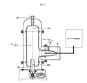
発明の名称が「炭質材料をガス化する方法(METHOD OF GASIFYING CARBONACEOUS MATERIALS)」の韓国特許第0391121(2003年6月30日)および米国特許第6790383号B2(2004年9月14日発行)には、炭質化合物(例えば、石炭、細断された廃タイヤまたは廃油)をガス状燃料(COおよびH2)へとガス化する方法および装置が記載されている。この装置では、リフォーマー・ボディー(還元反応チャンバー)と合成ガスバーナー(酸化反応チャンバー)とが、図1に示すように垂直に重ねられている。このような構成では、O2ガスを合成ガスバーナー内に保持しておく(または閉じ込めておく)ことが完全には保証されない。リフォーマーの処理量が増加するにつれ、合成ガスバーナー内で完全に消費されずに還元反応チャンバー内へと送られる合成ガスバーナー内のO2ガスがより多くなってしまう。更に、固体供給原料用の入口ポートは、還元反応チャンバー・ボディーの上部に配置されているものの、リフォーマー・ボディーの最も低温の箇所に配置されていないため、固体供給原料に対して最適に配置されていない。最も低温となる箇所は、リフォーマー・ボディーの底部である。 The titles of the invention are “Korean material materials gasification method (METHOD OF GASIFYING CARBONACEOUS MATERIALS)” and Korean Patent 0391121 (June 30, 2003) and US Pat. No. 6,790,383 B2 (issued September 14, 2004). Describes a method and apparatus for gasifying carbonaceous compounds (eg, coal, chopped waste tires or oil) into gaseous fuels (CO and H 2 ). In this apparatus, a reformer body (reduction reaction chamber) and a synthesis gas burner (oxidation reaction chamber) are vertically stacked as shown in FIG. In such a configuration, it is not completely guaranteed that the O 2 gas is retained (or confined) in the synthesis gas burner. As the reformer throughput increases, more O 2 gas in the synthesis gas burner is sent into the reduction reaction chamber without being completely consumed in the synthesis gas burner. In addition, although the inlet port for the solid feed is located at the top of the reduction reaction chamber body, it is not optimally located for the solid feed because it is not located at the coldest point of the reformer body. Not. The coldest spot is the bottom of the reformer body.
発明の要旨
ある要旨において、本発明の目的は、ガス化方法に最も適した装置を提供することである。本発明の装置は、単一段階リアクター内の全ての炭質材料を合成ガスに転化する汎用リフォーマー(または汎用改質装置)であり得る。このリフォーマーは、廃棄物のガス化に特に適している。なぜなら、リアクターの還元チャンバー内にO2ガスが入り込むことがないので、供給原料の酸化生成物は存在せず、2次汚染が生じないからである。このような反応条件下では、全ての炭質物がCOガスおよびH2ガスに転化されることになる。
SUMMARY OF THE INVENTION In one aspect of the invention, an object of the present invention is to provide an apparatus most suitable for a gasification method. The apparatus of the present invention can be a universal reformer (or universal reformer) that converts all carbonaceous material in a single stage reactor to syngas. This reformer is particularly suitable for waste gasification. This is because O 2 gas does not enter the reduction chamber of the reactor, so there is no oxidation product of the feedstock and secondary contamination does not occur. Under such reaction conditions, all the carbonaceous matter is converted into CO gas and H 2 gas.
ある態様において、ガス化リアクターは、還元反応が生じる還元反応チャンバー、および酸化反応が生じる酸化反応チャンバーを含んでいる。酸化反応チャンバーは、還元反応チャンバーに実質的に直交するように配置されている。酸化反応チャンバーが還元チャンバーに実施的に直交するように配置されているために、O2ガスがバーナー内に好ましく保持され、完全に消費されることになる。結果的には、還元反応チャンバー内にO2ガスがほぼ入り込むことはない。酸化反応チャンバーは、ガス入口およびガス出口を含んでいる。酸化チャンバーのガス出口は、還元反応チャンバーのガス入口と流体連通状態にある。 In some embodiments, the gasification reactor includes a reduction reaction chamber in which a reduction reaction occurs and an oxidation reaction chamber in which an oxidation reaction occurs. The oxidation reaction chamber is disposed so as to be substantially orthogonal to the reduction reaction chamber. Since the oxidation reaction chamber is arranged to be substantially orthogonal to the reduction chamber, O 2 gas is preferably held in the burner and is completely consumed. As a result, almost no O 2 gas enters the reduction reaction chamber. The oxidation reaction chamber includes a gas inlet and a gas outlet. The gas outlet of the oxidation chamber is in fluid communication with the gas inlet of the reduction reaction chamber.
ある詳細な態様において、酸化チャンバーは、合成ガスを受ける第1ガス入口、および酸素ガスを受ける1対の第2ガス入口を含んでいる。また、酸化チャンバーは、反応を開始するためのイグニッション穴(または点火用の穴)を含んでいる。 In one detailed aspect, the oxidation chamber includes a first gas inlet for receiving synthesis gas and a pair of second gas inlets for receiving oxygen gas. The oxidation chamber also includes an ignition hole (or ignition hole) for initiating the reaction.
還元反応チャンバーは、実質的に垂直方向に設けられており、ガス出口の下方にガス入口が配置されている。また、還元反応チャンバーには、炭質材料を受ける供給原料入口が還元反応チャンバーの底部に設けられている。還元反応チャンバーに隣接して配置されるスクリュー・フィーダーによって、固体供給原料が還元反応チャンバーの入口へと送られることになる。 The reduction reaction chamber is provided in a substantially vertical direction, and a gas inlet is disposed below the gas outlet. Further, the feedstock inlet for receiving the carbonaceous material is provided in the reduction reaction chamber at the bottom of the reduction reaction chamber. A screw feeder located adjacent to the reduction reaction chamber will cause the solid feed to be sent to the inlet of the reduction reaction chamber.
別の詳細な態様において、還元反応チャンバーは、実質的に垂直方向に設けられており、還元反応チャンバーのガス出口の下方にガス入口が配置されている。また、還元反応チャンバーには、炭質材料を受ける供給原料入口が還元反応チャンバーの底部に設けられている。還元反応チャンバーに隣接して配置されるスクリュー・フィーダーによって、固体供給原料が還元反応チャンバーの入口へと送られる。 In another detailed aspect, the reduction reaction chamber is provided in a substantially vertical direction, and a gas inlet is disposed below the gas outlet of the reduction reaction chamber. Further, the feedstock inlet for receiving the carbonaceous material is provided in the reduction reaction chamber at the bottom of the reduction reaction chamber. A solid feeder is sent to the inlet of the reduction reaction chamber by a screw feeder located adjacent to the reduction reaction chamber.
別の詳細な態様において、還元反応チャンバーは、内側ライニング、絶縁層および外側層を含んでいる。 In another detailed aspect, the reduction reaction chamber includes an inner lining, an insulating layer, and an outer layer.
ある態様において、酸化反応チャンバーは合成ガスバーナーであってもよい。合成ガスがO2と共に燃焼させられると、2000℃よりも高い温度の過熱蒸気(H2O分子)とCO2分子とから成るストリームが生じることになる。固体炭質原料用のフィーダーはリアクターの底部に配置される。 In some embodiments, the oxidation reaction chamber may be a syngas burner. When the synthesis gas is burned with O 2 , a stream consisting of superheated steam (H 2 O molecules) and CO 2 molecules at temperatures above 2000 ° C. will be produced. A feeder for solid carbonaceous feedstock is placed at the bottom of the reactor.
別の態様において、酸化反応チャンバーは、ブラウンガス・バーナーである。ブラウンガス・バーナーは、ブラウンガス用の入口、イグニッション穴、および還元反応チャンバーにつながる出口を含み得る。 In another embodiment, the oxidation reaction chamber is a brown gas burner. The brown gas burner may include an inlet for brown gas, an ignition hole, and an outlet leading to a reduction reaction chamber.
本発明の別の要旨は、燃料電池を駆動させるためのシステムおよび方法を特徴としている。ある態様では、そのシステムは、リフォーマー装置および燃料電池を含んでいる。例えば、リフォーマー装置は、ガス状および液体の化石燃料用の入口、および熱水およびCO2用の入口、および合成ガス用の出口を有している。ある詳細な態様において、電気ヒーターがリフォーマー装置に接している。燃料電池は、合成ガス用の入口およびO2ガス用の入口を含んでいる。また、そのシステムは、燃料電池から電気ヒーターへと電力(またはエネルギー)を伝える手段、および燃料電池からリフォーマー装置へと熱水およびCO2を移送する手段を含んでいる。 Another aspect of the invention features a system and method for driving a fuel cell. In some embodiments, the system includes a reformer device and a fuel cell. For example, reformer device includes gaseous and inlet for fossil fuel liquid and an inlet for hot water and CO 2, and an outlet for synthesis gas. In certain detailed embodiments, an electric heater is in contact with the reformer device. The fuel cell includes an inlet for synthesis gas and an inlet for O 2 gas. The system also includes means for transferring power (or energy) from the fuel cell to the electric heater and means for transferring hot water and CO 2 from the fuel cell to the reformer device.
リフォーマー装置は、燃料電池に送られる合成ガスを生じる。また、酸素ガスが燃料電池内に送られる。燃料電池は、熱水、およびリフォーマーに送られるCO2を生じる。燃料電池で生じるエネルギーは、リフォーマーを加熱するのに用いられる。 The reformer device produces syngas that is sent to the fuel cell. Also, oxygen gas is sent into the fuel cell. The fuel cell produces hot water and CO 2 that is sent to the reformer. The energy generated in the fuel cell is used to heat the reformer.
本発明は、
還元反応チャンバー(または還元チャンバー)、および
還元反応チャンバーに実質的に直交するように配置される酸化反応チャンバー(または酸化チャンバー)
を有して成るガス化リアクターであって、
還元反応チャンバーが、供給原料入口、ガス出口、供給原料入口からガス出口に至るまで延在するボディー、およびボディーの側部に配置されるガス入口を有して成り、
酸化反応チャンバーが、ガス入口およびガス出口を有して成り、また
酸化チャンバーのガス出口が還元反応チャンバーのガス入口と流体連通状態にある、ガス化リアクターを対象としている。
The present invention
Reduction reaction chamber (or reduction chamber), and oxidation reaction chamber (or oxidation chamber) arranged substantially orthogonal to the reduction reaction chamber
A gasification reactor comprising:
The reduction reaction chamber comprises a feedstock inlet, a gas outlet, a body extending from the feedstock inlet to the gas outlet, and a gas inlet disposed on a side of the body;
The oxidation reaction chamber is directed to a gasification reactor comprising a gas inlet and a gas outlet, and the gas outlet of the oxidation chamber is in fluid communication with the gas inlet of the reduction reaction chamber.
別の要旨において、還元チャンバーでは少なくとも1200℃の温度で還元が生じる。 In another aspect, the reduction occurs in the reduction chamber at a temperature of at least 1200 ° C.
別の要旨において、還元反応チャンバーのガス入口およびガス出口は、ガス入口がガス出口の下方になるように実質的に垂直方向に設けられている。また、酸化反応チャンバーのガス入口およびガス出口は実質的に水平方向に設けられている。 In another aspect, the gas inlet and the gas outlet of the reduction reaction chamber are provided in a substantially vertical direction such that the gas inlet is below the gas outlet. Further, the gas inlet and the gas outlet of the oxidation reaction chamber are provided in a substantially horizontal direction.
別の要旨において、還元反応チャンバーは、1200℃よりも高い温度にて物理的および化学的に安定な材料から成る内側ライニングを有して成る。更に別の要旨において、内側ライニング材料はセラミック材料である。また、更に別の要旨において、内側ライニング材料が酸化アルミニウム・セラミックである。 In another aspect, the reduction reaction chamber comprises an inner lining made of a material that is physically and chemically stable at temperatures above 1200 ° C. In yet another aspect, the inner lining material is a ceramic material. In yet another aspect, the inner lining material is an aluminum oxide ceramic.
別の要旨において、還元反応チャンバーは、外側金属ケーシングを有して成る。更なる要旨において、外側ケーシングがステンレス鋼から形成されている。 In another aspect, the reduction reaction chamber comprises an outer metal casing. In a further aspect, the outer casing is formed from stainless steel.
別の要旨において、還元反応チャンバーは、内側ライニング材料を更に有して成り、外側金属ケーシングと内側ライニング材料との間に内側絶縁層が配置される。更に別の要旨において、内側絶縁層は、約100mm〜約150mmの厚さを有している。更に別の要旨において、内側絶縁層は、キャスタブル(castable)とロックウール(rock wool)とから成る複合材料から成っている。 In another aspect, the reduction reaction chamber further comprises an inner lining material, and an inner insulating layer is disposed between the outer metal casing and the inner lining material. In yet another aspect, the inner insulating layer has a thickness of about 100 mm to about 150 mm. In yet another aspect, the inner insulating layer is made of a composite material consisting of castable and rock wool.
ある要旨において、酸化反応チャンバーは合成ガスバーナーである。別の要旨において、酸化反応チャンバーはブラウンガス・バーナーである。 In one aspect, the oxidation reaction chamber is a synthesis gas burner. In another aspect, the oxidation reaction chamber is a brown gas burner.
ある要旨において、供給原料入口は固体供給原料入口を有して成る。別の要旨において、供給原料入口は液体供給原料入口を有して成る。別の要旨において、固体供給原料の導入が制御されるように、還元反応チャンバーの供給原料入口に隣接してスクリュー・フィーダーが配置される。 In one aspect, the feedstock inlet comprises a solid feedstock inlet. In another aspect, the feedstock inlet comprises a liquid feedstock inlet. In another aspect, a screw feeder is positioned adjacent to the feed inlet of the reduction reaction chamber so that the introduction of solid feed is controlled.
ある要旨において、酸化反応チャンバーのガス入口は、合成ガスを受ける第1ガス入口、および酸素ガスを受ける一対の第2ガス入口を有して成る。更なる態様において、一対の第2ガス入口が、第1ガス入口の両側に配置されており、酸素ガスと合成ガスとがチャンバー内に入った後で反応するように、一対の第2ガス入口が第1ガス入口に対して角度を成して設けられている。 In one aspect, the gas inlet of the oxidation reaction chamber comprises a first gas inlet for receiving synthesis gas and a pair of second gas inlets for receiving oxygen gas. In a further aspect, the pair of second gas inlets are disposed on opposite sides of the first gas inlet, and the pair of second gas inlets are reacted so that oxygen gas and synthesis gas react after entering the chamber. Is provided at an angle to the first gas inlet.
ある要旨において、還元反応チャンバーに酸素が入り込まないように、酸化チャンバーに入れられた酸素が十分に消費される。 In one aspect, to prevent oxygen from entering the reduction reaction chamber, oxygen was found placed in the oxidation chamber is fully consumed.
別の要旨において、合成ガスと酸素ガスとが、酸化反応チャンバー内でCO2およびH2Oガスに転化される。ある要旨において、CO2とH2Oガスが2000℃よりも高い温度にされる。 In another aspect, synthesis gas and oxygen gas are converted to CO 2 and H 2 O gas in an oxidation reaction chamber. In one aspect, the CO 2 and H 2 O gases are brought to a temperature higher than 2000 ° C.
更なる要旨において、合成ガスが還元反応チャンバーのガス出口から排出される。別の要旨において、排出された合成ガスが100℃以下にまで冷却され、貯留タンクに貯留される。更に別の態様において、排出された合成ガスが熱交換機を通ることによって冷却される。更なる態様において、排出された合成ガスの一部が酸化反応チャンバーへとリサイクルされる。 In a further aspect, synthesis gas is discharged from the gas outlet of the reduction reaction chamber. In another aspect, the discharged synthesis gas is cooled to 100 ° C. or less and stored in a storage tank. In yet another aspect, the exhausted synthesis gas is cooled by passing through a heat exchanger. In a further embodiment, a portion of the exhausted synthesis gas is recycled to the oxidation reaction chamber.
また、本発明では、
炭質物を改質する方法であって、
還元反応チャンバーおよび酸化反応チャンバーを有して成り、酸化反応チャンバーが還元反応チャンバーに実質的に直交するように配置されているガス化リアクターを供すること、
酸素ガスと合成ガスとを酸化反応チャンバー内に導入すること、
酸化反応チャンバー内で酸素ガスおよび合成ガスをH2OおよびCO2ガスに転化すること、
H2OおよびCO2ガスを還元チャンバー内に供給すること、
炭質物を含んで成る供給原料を還元反応チャンバー内に導入すること、また
炭質物をH2ガスおよびCOガスへと転化すること
を含んで成る方法が提供される。
In the present invention,
A method of modifying a carbonaceous material,
Providing a gasification reactor comprising a reduction reaction chamber and an oxidation reaction chamber, wherein the oxidation reaction chamber is arranged substantially perpendicular to the reduction reaction chamber;
Introducing oxygen gas and synthesis gas into the oxidation reaction chamber;
Converting oxygen gas and synthesis gas into H 2 O and CO 2 gas in an oxidation reaction chamber;
Supplying H 2 O and CO 2 gas into the reduction chamber;
There is provided a process comprising introducing a feedstock comprising a carbonaceous material into a reduction reaction chamber and converting the carbonaceous material to H 2 gas and CO gas.
本発明の別の要旨は、
炭質物を改質する方法であって、
還元反応チャンバーおよび酸化反応チャンバーを有して成り、酸化反応チャンバーが還元反応チャンバーに実質的に直交するように配置されているガス化リアクターを供すること、
酸素と水素とから成るブラウンガスを酸化反応チャンバー内に導入すること、
酸化反応チャンバー内で酸素および水素ガスをH2Oガスに転化すること、
H2Oガスを還元チャンバー内に供給すること、
炭質物を含んで成る供給原料を還元反応チャンバー内に導入すること、また
炭質物をH2およびCOガスへと転化すること
を含んで成る方法を対象としている。
Another gist of the present invention is as follows:
A method of modifying a carbonaceous material,
Providing a gasification reactor comprising a reduction reaction chamber and an oxidation reaction chamber, wherein the oxidation reaction chamber is arranged substantially perpendicular to the reduction reaction chamber;
Introducing brown gas consisting of oxygen and hydrogen into the oxidation reaction chamber;
Converting oxygen and hydrogen gas to H 2 O gas in an oxidation reaction chamber;
Supplying H 2 O gas into the reduction chamber;
It is directed to a process comprising introducing a feed comprising carbonaceous material into a reduction reaction chamber and converting the carbonaceous material to H 2 and CO gas.
ある要旨において、触媒の不存在下で炭質物を転化する。 In one aspect, the carbonaceous material is converted in the absence of a catalyst.
本発明の別の要旨において、
燃料電池;および
燃料電池と連通状態にあるリフォーマー
を有して成り、
リフォーマー・ボディーが、合成ガスを発生させて、それを燃料電池に供給するように構成されており、また
燃料電池で生じるH2OおよびCO2の少なくとも一部が、更なる合成ガスを発生させるためにリフォーマーに供給される、
燃料電池を駆動させるためのシステムが提供される。
In another aspect of the invention,
A fuel cell; and a reformer in communication with the fuel cell;
The reformer body is configured to generate synthesis gas and supply it to the fuel cell, and at least a portion of the H 2 O and CO 2 generated in the fuel cell generates additional synthesis gas. To be supplied to the reformer,
A system for driving a fuel cell is provided.
ある要旨において、システムは、リフォーマーを加熱する加熱機構を更に有して成り、燃料電池で生じる電力の少なくとも一部によって加熱機構にエネルギーを供給する。別の要旨において、リフォーマーが、化石燃料を受ける第1入口、H2OおよびCO2を受ける第2入口、および合成ガスを排出する出口を有して成る。ある要旨において、化石燃料が、液体化石燃料を含んで成る。別の要旨において、化石燃料が、ガス状化石燃料を含んで成る。 In one aspect, the system further comprises a heating mechanism that heats the reformer and provides energy to the heating mechanism by at least a portion of the power generated in the fuel cell. In another aspect, the reformer comprises a first inlet that receives fossil fuel, a second inlet that receives H 2 O and CO 2 , and an outlet that discharges syngas. In one aspect, the fossil fuel comprises a liquid fossil fuel. In another aspect, the fossil fuel comprises gaseous fossil fuel.
ある要旨において、リフォーマー・ボディーのサイズは、約3リットル以下である。 In one aspect, the reformer body size is about 3 liters or less.
本発明の別の要旨では、
燃料電池を駆動させる方法であって、
燃料電池と流体連通状態にあるリフォーマー装置内で化石燃料を合成ガスへと改質すること;
O2ガスを燃料電池に供給すること;
燃料電池からH2OおよびCO2をリフォーマーへと移送させること;また
燃料電池で生じる電力の少なくとも一部を用いてリフォーマーを加熱すること
を含んで成る方法が提供される。
In another aspect of the invention,
A method of driving a fuel cell,
Reforming fossil fuel into syngas in a reformer device in fluid communication with the fuel cell;
Supplying O 2 gas to the fuel cell;
There is provided a method comprising transferring H 2 O and CO 2 from a fuel cell to a reformer; and heating the reformer with at least a portion of the power generated in the fuel cell.
図面を含め、本発明の好ましい態様の詳細な説明によって、本発明の上述の特徴および他の特徴が明らかになるであろう。 The foregoing and other features of the present invention will become apparent from the detailed description of the preferred embodiments of the invention, including the drawings.
発明を実施するための最良の形態
図1に示すようなリフォーマーでは、酸化チャンバーと還元チャンバーとが垂直に積み重ねられており、固体供給原料を導入するのに好ましい機構となっていない。このような装置では、図1に示すように、リフォーマー・ボディー(還元反応チャンバー)と合成ガスバーナー(酸化反応チャンバー)とが垂直に重ねられている。このような構成では、O2ガスを合成ガスバーナー内に保持しておくことが完全には保証されない。リフォーマーの処理量が増加するにつれ、合成ガスバーナー内で完全に消費されることなく還元チャンバー内へと送られる合成ガスバーナー内のO2ガスが多くなってしまう。更に、固体供給原料用の入口ポートが、還元反応チャンバー・ボディーの上部に配置されているものの、リフォーマー・ボディーの最も低温の箇所に配置されていないため、固体供給原料に対して最適に配置されていない。最も低温の箇所は、リフォーマー・ボディーの底部である。
BEST MODE FOR CARRYING OUT THE INVENTION In the reformer as shown in FIG. 1, the oxidation chamber and the reduction chamber are stacked vertically, which is not a preferable mechanism for introducing the solid feedstock. In such an apparatus, as shown in FIG. 1, a reformer body (reduction reaction chamber) and a synthesis gas burner (oxidation reaction chamber) are vertically stacked. In such a configuration, it is not completely guaranteed that the O 2 gas is retained in the synthesis gas burner. As the reformer throughput increases, more O 2 gas in the synthesis gas burner is sent into the reduction chamber without being completely consumed in the synthesis gas burner. Furthermore, although the inlet port for the solid feed is located at the top of the reduction reaction chamber body, it is not located at the coldest part of the reformer body, so it is optimally located for the solid feed. Not. The coldest spot is the bottom of the reformer body.
図2を参照すると、ある態様において、本発明のリフォーマー装置は、還元反応チャンバー(リフォーマー・ボディー)および酸化反応チャンバー(合成ガスバーナー)を含んでいる。 Referring to FIG. 2, in one embodiment, the reformer apparatus of the present invention includes a reduction reaction chamber (reformer body) and an oxidation reaction chamber (syngas burner).
還元反応チャンバーは、供給原料入口5、ガス出口4およびボディーを含んでいる。ボディーは、供給原料入口5からガス出口4に及ぶように延在している。図2に示す態様において、リフォーマー装置は円筒形状を有している。別法にて、リフォーマー装置は、還元反応を可能にするのに十分な別の形状およびサイズを有するものであってもよい。固体の供給原料は、リフォーマー・ボディーの底部にて供給原料入口5を介して導入される。固体の供給材料は石炭または廃棄物であってよい。例えば、石炭ならびに細断および脱ガス化したプラスチック廃棄物等の固体供給原料を、リフォーマーの底部に設けられているスクリュー・フィーダー10によってリフォーマー内に送ってもよい。スクリュー・フィーダーの操作は、当業者に周知である。ホッパー19によって固体廃棄物をスクリュー・フィーダー内に導入してもよい。
The reduction reaction chamber includes a feedstock inlet 5, a
図2の態様では、酸化反応チャンバー(合成ガスバーナー)が、還元反応チャンバーに実質的に直交するように配置されている。酸化反応チャンバーは、ガス入口17を含んでいる。酸化反応によって生じるガスは、還元反応チャンバー内に導入される。この態様では、酸化反応チャンバーと還元反応チャンバーとが、かなり良好に分けられており、それゆえ、酸化反応チャンバーに入れられた酸素が十分に消費され、還元反応チャンバー内へと酸素ガスが進入することが防止されている。
In the embodiment of FIG. 2, the oxidation reaction chamber (syngas burner) is disposed so as to be substantially orthogonal to the reduction reaction chamber. The oxidation reaction chamber includes a gas inlet 17. The gas generated by the oxidation reaction is introduced into the reduction reaction chamber. In this manner, an oxidation reaction chamber and reduction reaction chamber are divided fairly good, therefore, is consumed sufficiently put al the oxygen in the oxidation reaction chamber, oxygen gas and is the reduction reaction chamber It is prevented from entering.
1つの詳細な態様において、ガス入口17を介して酸化反応チャンバー内に合成ガスが導入され、また、ガス入口17の両側に設けられた一対のガス入口16を介して酸化反応チャンバー内に酸素が導入される。また、酸化反応チャンバー内に酸素ガスが角度を成して導入されるように、入口16が角度を成して設けられている。これによって、酸素ガスと合成ガスとが相互に合わせられ、効率的な反応が可能となる。イグニッション穴18が設けられており、反応の点火が可能となっている。 In one detailed embodiment, synthesis gas is introduced into the oxidation reaction chamber via the gas inlet 17, and oxygen is introduced into the oxidation reaction chamber via a pair of gas inlets 16 provided on both sides of the gas inlet 17. be introduced. The inlet 16 is provided at an angle so that oxygen gas is introduced into the oxidation reaction chamber at an angle. Thereby, the oxygen gas and the synthesis gas are combined with each other, and an efficient reaction is possible. An ignition hole 18 is provided so that the reaction can be ignited.
ある態様において、還元反応チャンバーおよび酸化反応チャンバーの各々は、外側金属ケーシング1および内側ライニング3を含んでいる。外側金属ケーシングは、例えばステンレス鋼から形成されてもよい。内側ライニングは、例えば、酸化アルミニウムセラミック等のセラミック材料であってもよい。好ましくは、内側ライニングは、1200℃よりも高い温度に対して耐性を有する材料で形成されている。別の態様において、金属ケーシングと内側ライニングとの間に内側絶縁材2が設けられる。絶縁層は、例えば、約100mm〜約150mmの厚さを有するものであってよい。内側絶縁層は、キャスタブルとロックウールとから成る複合材料から形成してもよい。
In some embodiments, each of the reduction reaction chamber and the oxidation reaction chamber includes an outer metal casing 1 and an inner lining 3. The outer metal casing may be formed from stainless steel, for example. The inner lining may be a ceramic material such as an aluminum oxide ceramic, for example. Preferably, the inner lining is made of a material that is resistant to temperatures above 1200 ° C. In another aspect, an
図3を参照すると、ガス化リアクターは、酸化反応チャンバーおよび還元反応チャンバーを含んでいる。ガス化リアクターの還元反応チャンバー(リフォーマー・ボディー)は、図2に示す還元反応チャンバーと実質的に同様である。この態様では酸化反応チャンバーはブラウンガス・バーナーである。酸化反応チャンバーには、入口17およびイグニッション穴18が設けられている。ある態様において、ブラウンガスが、ブラウンガス発生機から入口17へと送られる。 Referring to FIG. 3, the gasification reactor includes an oxidation reaction chamber and a reduction reaction chamber. The reduction reaction chamber (reformer body) of the gasification reactor is substantially the same as the reduction reaction chamber shown in FIG. In this embodiment, the oxidation reaction chamber is a brown gas burner. The oxidation reaction chamber is provided with an inlet 17 and an ignition hole 18. In some embodiments, brown gas is sent from the brown gas generator to the inlet 17.
本発明に従って、図2に示すリフォーマーの操作を以下に示す。
(1)ガス化リアクターを室温に付し、その後、合成ガスバーナー(図2)内の合成ガスを燃焼することによってガス化リアクターをゆっくり加熱することによって、炭質材料のガス化反応を開始する。予備加熱(または予め加熱を行うこと)を実施する必要はない。
(2)合成ガス貯留タンクから合成ガス入口17を介して合成ガスバーナー内に合成ガス(合成ガスが利用できない場合はH2ガス)を導入する。次いで、酸素ガスを酸素ガス入口16を介して合成ガスバーナー内に導入する。イグニッション穴18を介して口火を導入することによって、合成ガスを燃焼させる。合成ガス(またはH2ガス)が燃焼すると、温度が急に上昇することになる。生成ガス出口4において酸素をモニタリングして酸素の取り込み(または供給)を調整することによって、温度を制御する。加熱段階の最後では、まず酸素ガスの供給を止め、その後、合成ガスの供給を止めることによって温度を下げる。
このようにして、酸素の流入量を制御して酸化反応リアクターの温度を1200℃よりも大きくすると、酸化反応チャンバーが、合成ガスと酸素との反応で生じたCO2およびH2Oで満たされることになる。
(3)還元反応チャンバーの温度を1200℃よりも高く維持しつつ、固体炭質材料(圧縮、脱ガス化および乾燥に予め付した固体炭質材料)を入口5を介してリアクター内に供給する。1200℃よりも高い温度条件下では、炭質材料は、合成ガスバーナーから供給される過熱CO2/H2O分子と迅速に反応し、主成分がCOおよびH2の合成ガスが生じることになる。還元反応が進行するにつれ、リアクター温度は約1200℃に落ち着くことになる。
(4)ガス化反応の間に生じる合成ガスは、還元反応チャンバーの上方端部のガス出口4から排出する。約1200℃にて還元反応チャンバーから排出された合成ガスは、熱交換機を通して100℃以下にまで冷却され、貯留タンク(図2において図示せず)に貯留されることになる。
(5)貯留タンク(図2において図示せず)からリサイクルされた合成ガスは、合成ガスバーナーで酸素と反応させることによって、熱が発生するH2OおよびCO2の生成に用いてもよい。つまり、リアクターを1200℃に維持するのに必要な熱源は、生じた合成ガス(酸素と反応することになる)の一部をリサイクルすることによって得る。この際、リアクター内の温度は、酸素ガスの合成ガスバーナーへの供給を制御することによって調整される。リサイクルされた合成ガスの燃焼生成物は、有機供給材料の炭素原子を転化させて、合成ガスを生じる。合成ガスバーナー内で未反応なままで存在するリサイクルされた合成ガスは、生成した合成ガスの残りと共にリアクターから排出させる。
In accordance with the present invention, the operation of the reformer shown in FIG.
(1) The gasification reactor is brought to room temperature and then the gasification reaction of the carbonaceous material is started by slowly heating the gasification reactor by burning the synthesis gas in the synthesis gas burner (FIG. 2). It is not necessary to perform preheating (or preheating).
(2) The synthesis gas (or H 2 gas when synthesis gas is not available) is introduced from the synthesis gas storage tank into the synthesis gas burner via the synthesis gas inlet 17. Oxygen gas is then introduced into the synthesis gas burner via the oxygen gas inlet 16. By introducing a spark through the ignition hole 18, the synthesis gas is combusted. When synthesis gas (or H 2 gas) burns, the temperature will rise rapidly. Temperature is controlled by monitoring oxygen at the
In this way, when the inflow of oxygen is controlled and the temperature of the oxidation reaction reactor is made higher than 1200 ° C., the oxidation reaction chamber is filled with CO 2 and H 2 O generated by the reaction between the synthesis gas and oxygen. It will be.
(3) A solid carbonaceous material (solid carbonaceous material previously subjected to compression, degasification and drying) is supplied into the reactor through the inlet 5 while maintaining the temperature of the reduction reaction chamber higher than 1200 ° C. Under temperature conditions higher than 1200 ° C., the carbonaceous material reacts rapidly with superheated CO 2 / H 2 O molecules supplied from the synthesis gas burner, resulting in synthesis gas whose main components are CO and H 2. . As the reduction reaction proceeds, the reactor temperature will settle to about 1200 ° C.
(4) The synthesis gas generated during the gasification reaction is discharged from the
(5) The synthesis gas recycled from the storage tank (not shown in FIG. 2) may be used to generate H 2 O and CO 2 that generate heat by reacting with oxygen with a synthesis gas burner. That is, the heat source necessary to maintain the reactor at 1200 ° C. is obtained by recycling a portion of the resulting synthesis gas (which will react with oxygen). At this time, the temperature in the reactor is adjusted by controlling the supply of oxygen gas to the synthesis gas burner. The recycled synthesis gas combustion products convert the carbon atoms of the organic feedstock to produce synthesis gas. Recycled synthesis gas that remains unreacted in the synthesis gas burner is discharged from the reactor along with the remainder of the synthesis gas produced.
図3に示すリフォーマーの操作は、図2に示すリフォーマーの操作と実質的に同様である。主な違いは、合成ガスの代わりに、図3に示すように、ブラウンガス・バーナー内でブラウンガス(H2とO2とから成るガス混合物)を燃焼させ、相当により高い温度(2500℃よりも高い温度)でH2Oを発生させることである。過熱H2Oを還元反応チャンバー内に移送し、リアクターの温度を1200℃よりも高い温度に維持し、炭質物をCOガスおよびH2ガスへと変換する。ブラウンガス・バーナーの操作は簡単であり、図2の合成ガスバーナーの補助バーナー(または予備バーナー)として機能し得る。ブラウンガス発生機は、韓国のベストコリア株式会社(BEST KOREA Co.)から市販されている。ブラウンガス発生機を使用することによって、ガス処理装置が相当シンプルになる。ブラウンガス・バーナーは必ずしもO2ガス入口を別途必要としない。なぜなら、ブラウンガスというのは、水の電気分解によって生じるH2ガスおよびO2ガスがバランスの取れた割合で含まれる混合物であるからである。 The operation of the reformer shown in FIG. 3 is substantially the same as the operation of the reformer shown in FIG. The main difference is that instead of synthesis gas, brown gas (a gas mixture of H 2 and O 2 ) is burned in a brown gas burner, as shown in FIG. H 2 O is generated at a high temperature). Superheated H 2 O is transferred into the reduction reaction chamber, the temperature of the reactor is maintained at a temperature higher than 1200 ° C., and the carbonaceous matter is converted into CO gas and H 2 gas. The operation of the brown gas burner is simple and can function as an auxiliary burner (or spare burner) for the synthesis gas burner of FIG. Brown gas generators are commercially available from BEST KOREA Co., Korea. By using a brown gas generator, the gas processing device is considerably simplified. Brown gas burners do not necessarily require a separate O 2 gas inlet. This is because the brown gas is a mixture containing H 2 gas and O 2 gas generated by electrolysis of water in a balanced ratio.
上述のように、合成ガスバーナーを備えたガス化リアクターで炭質材料をガス化する方法においては、合成ガスバーナー内でのみ酸化反応が実施され、リフォーマー(還元反応チャンバー)内に酸素が入り込むことはない。リフォーマーでは、H2O、CO2、H2およびCOガスのみが存在することになる。それゆえ、リフォーマー内に炭質供給原料の酸化生成物が存在することはない。 As described above, in the method of gasifying a carbonaceous material in a gasification reactor equipped with a synthesis gas burner, an oxidation reaction is performed only in the synthesis gas burner, and oxygen enters the reformer (reduction reaction chamber). Absent. In the reformer, only H 2 O, CO 2 , H 2 and CO gas will be present. Therefore, there is no oxidation product of the carbonaceous feedstock in the reformer.
本発明のリフォーマーは、医療廃棄物を含む炭素系廃棄物をガス化するのに特に適当である。合成ガスバーナー(O2ガスよりも多くの合成ガスが存在する)での合成ガスの燃焼に起因して生じる発熱によって、リフォーマーが加熱される。リフォーマー内に酸素ガスが流れ込むことのないようにリフォーマーを操作することができる。それゆえ、改質リアクターは、1200℃よりも高い温度において、H2O、CO2、COおよびH2ガスで満たされることになる。このような条件下では、全ての炭素原子および水素原子は、COおよびH2ガスへと転化されることになる。酸化物を含む汚染物質は存在しない。供給原料中にClおよびSが含まれることからHClガスおよびH2Sガスが生じることが考えられるものの、比較的安価なクリーニング手段が存在する。このクリーニング手段は、有害な有機廃棄物に対しては特に、安全に処理する手段として知られているものである。合成ガスの生成に関して、供給原料は、きれいなものであったり、純粋な化石燃料であったりする必要はなく、種々の炭質物が考えられる。従って、水素ガスを製造するコストは、非常に競争力を有している。 The reformer of the present invention is particularly suitable for gasifying carbon-based waste including medical waste. The reformer is heated by the heat generated due to the combustion of the synthesis gas in the synthesis gas burner (there is more synthesis gas than O 2 gas). The reformer can be operated so that oxygen gas does not flow into the reformer. Therefore, the reforming reactor will be filled with H 2 O, CO 2 , CO and H 2 gases at temperatures above 1200 ° C. Under such conditions, all carbon and hydrogen atoms will be converted to CO and H 2 gas. There are no contaminants including oxides. Although it is conceivable that HCl gas and H 2 S gas are generated because Cl and S are contained in the feedstock, there are relatively inexpensive cleaning means. This cleaning means is known as a means for safely treating especially harmful organic waste. Regarding the production of synthesis gas, the feedstock need not be clean or pure fossil fuel, and various carbonaceous materials are conceivable. Therefore, the cost of producing hydrogen gas is very competitive.
図4は、
燃料電池;および
燃料電池と連通状態にあるリフォーマー
を有して成り、
リフォーマー・ボディーが、合成ガスを発生させて、それを燃料電池に供給するように構成されており、また
燃料電池で生じるH2OおよびCO2の少なくとも一部が、更なる合成ガスの発生のためにリフォーマーに供給される、
燃料電池を駆動させるためのシステムを表している。
FIG.
A fuel cell; and a reformer in communication with the fuel cell;
The reformer body is configured to generate synthesis gas and supply it to the fuel cell, and at least a portion of the H 2 O and CO 2 generated in the fuel cell is responsible for further synthesis gas generation. To be supplied to the reformer,
1 represents a system for driving a fuel cell.
図4に示すシステムは、
燃料電池を駆動させる方法であって、
燃料電池と流体連通状態にあるリフォーマー装置内で化石燃料を合成ガスへと改質すること;
O2ガスを燃料電池に供給すること;
燃料電池からH2OおよびCO2をリフォーマーに移送すること;また
燃料電池で生じる電力の少なくとも一部を用いてリフォーマーを加熱すること
を含んで成る方法に対して使用してもよい。
The system shown in FIG.
A method of driving a fuel cell,
Reforming fossil fuel into syngas in a reformer device in fluid communication with the fuel cell;
Supplying O 2 gas to the fuel cell;
It may also be used for a method comprising transferring H 2 O and CO 2 from a fuel cell to a reformer; and heating the reformer with at least a portion of the power generated in the fuel cell.
ある要旨において、システムが、リフォーマーを加熱する加熱機構を更に有して成り、燃料電池で生じる電力の少なくとも一部によって加熱機構にエネルギーが供給される。別の要旨において、リフォーマーが、化石燃料を受ける第1入口、H2OおよびCO2を受ける第2入口、および合成ガスを排出する出口を有して成る。 In one aspect, the system further comprises a heating mechanism that heats the reformer, and energy is supplied to the heating mechanism by at least a portion of the power generated in the fuel cell. In another aspect, the reformer comprises a first inlet that receives fossil fuel, a second inlet that receives H 2 O and CO 2 , and an outlet that discharges syngas.
特許的な立場から種々の態様および実施例を説明を行ってきたが、本発明の範囲はそのような態様および実施例に制限されるものではない。本発明の範囲および概念から逸脱することなく、本発明を修正および変更してもよいことは当業者に明らかであろう。 Although various embodiments and examples have been described from a patent standpoint, the scope of the present invention is not limited to such embodiments and examples. It will be apparent to those skilled in the art that modifications and variations can be made to the present invention without departing from the scope and concept of the invention.
それゆえ、本発明の範囲は、例示的な特定の実施例に依存するものではなく、特許請求の範囲によって規定されることを理解されよう。 Therefore, it will be appreciated that the scope of this invention is not dependent on the specific examples illustrated, but is defined by the claims.
Claims (32)
酸化反応チャンバー
を有して成るガス化リアクターであって、
還元反応チャンバーが、供給原料入口、ガス出口、供給原料入口からガス出口に至るまで延在する垂直軸に沿ったボディー、およびボディーの側部に配置されるガス入口を有して成り、
酸化反応チャンバーが、ガス入口およびガス出口を有して成り、酸化反応チャンバーのガス出口が還元反応チャンバーのガス入口と流体連通状態にあって、また
酸化反応チャンバーのガス出口から流出されるガスが還元反応チャンバーの垂直軸に対して実質的に直交するように、かつ、酸化反応チャンバーに入る実質的に全ての酸素ガスが酸化反応チャンバーで十分に消費されるように酸化反応チャンバーが配置されている、ガス化リアクター。 A reduction reaction chamber, and
A gasification reactor comprising a oxidation reaction chamber,
The reduction reaction chamber comprises a feedstock inlet, a gas outlet, a body along a vertical axis extending from the feedstock inlet to the gas outlet, and a gas inlet disposed on a side of the body;
The oxidation reaction chamber, Ri formed a gas inlet and a gas outlet, the gas outlet of the oxidation reaction chamber I gas inlet in fluid communication with the near-reduction reaction chamber, also
The gas exiting from the gas outlet of the oxidation reaction chamber is substantially perpendicular to the vertical axis of the reduction reaction chamber, and substantially all oxygen gas entering the oxidation reaction chamber is sufficient in the oxidation reaction chamber. A gasification reactor in which an oxidation reaction chamber is arranged to be consumed .
酸化反応チャンバーのガス入口およびガス出口は実質的に水平方向に設けられている
請求項1に記載のガス化リアクター。 The gas inlet and gas outlet of the reduction reaction chamber are provided in a substantially vertical direction such that the gas inlet is located below the gas outlet, and the gas inlet and gas outlet of the oxidation reaction chamber are substantially horizontal. The gasification reactor according to claim 1, which is provided in a direction.
酸素ガスと合成ガスとがチャンバー内に入った後で反応するように、一対の第2ガス入口が第1ガス入口に対して角度を成して設けられている、請求項13に記載のガス化リアクター。 A pair of second gas inlets are disposed on both sides of the first gas inlet, and the pair of second gas inlets are in contact with the first gas so that oxygen gas and synthesis gas react after entering the chamber. The gasification reactor according to claim 13, wherein the gasification reactor is provided at an angle with respect to the inlet.
垂直軸を有する還元反応チャンバーおよび酸化反応チャンバーを有して成るガス化リアクターを供すること、
酸素ガスと合成ガスとを酸化反応チャンバー内に導入すること、
還元反応チャンバーで1200℃よりも高い温度が維持されるのに十分な熱エネルギーが供されるように、酸化反応チャンバー内で酸素ガスおよび合成ガスを水蒸気およびCO2ガスに転化すること、
水蒸気およびCO2ガスを還元反応チャンバー内に供給すること、
炭質物を含んで成る供給原料を還元反応チャンバー内に導入すること、また
1200℃よりも高い温度にて炭質物を合成ガスへと転化すること
を含んで成り、
酸化反応チャンバーからのガスが還元反応チャンバーの垂直軸に実質的に直交して還元反応チャンバー内へと流入することになるように酸化反応チャンバーが配置されており、
酸化反応チャンバー内での実質的に全ての酸素ガスの十分な消費が、還元反応チャンバーに対する酸化反応チャンバーの配置によって行われている、方法。 A method of modifying a carbonaceous material,
Providing a gasification reactor comprising a reduction reaction chamber having a vertical axis and an oxidation reaction chamber;
Introducing oxygen gas and synthesis gas into the oxidation reaction chamber;
Converting oxygen gas and synthesis gas into water vapor and CO 2 gas in the oxidation reaction chamber so that sufficient thermal energy is provided to maintain a temperature above 1200 ° C. in the reduction reaction chamber;
Supplying water vapor and CO 2 gas into the reduction reaction chamber;
Introducing a feedstock comprising carbonaceous material into the reduction reaction chamber, and converting the carbonaceous material to synthesis gas at a temperature greater than 1200 ° C;
The oxidation reaction chamber is arranged so that the gas from the oxidation reaction chamber flows into the reduction reaction chamber substantially perpendicular to the vertical axis of the reduction reaction chamber,
A method wherein sufficient consumption of substantially all of the oxygen gas in the oxidation reaction chamber is effected by the arrangement of the oxidation reaction chamber relative to the reduction reaction chamber .
垂直軸を有する還元反応チャンバーおよび酸化反応チャンバーを有して成るガス化リアクターを供すること、
酸素と水素とから成るブラウンガスを酸化反応チャンバー内に導入すること、
酸化反応チャンバー内で酸素および水素ガスを水蒸気に転化すること、
還元反応チャンバーで1200℃よりも高い温度が維持されるのに十分な熱が供されるように、水蒸気を還元反応チャンバー内に供給すること、
炭質物を含んで成る供給原料を還元反応チャンバー内に導入すること、また
1200℃よりも高い温度にて炭質物をH2およびCOガスへと転化すること
を含んで成り、
酸化反応チャンバーからのガスが還元反応チャンバーの垂直軸に実質的に直交して還元反応チャンバー内へと流入することになるように酸化反応チャンバーが配置されており、
酸化反応チャンバー内での実質的に全ての酸素ガスの十分な消費が、還元反応チャンバーに対する酸化反応チャンバーの配置によって行われている、方法。 A method of modifying a carbonaceous material,
Providing a gasification reactor comprising a reduction reaction chamber having a vertical axis and an oxidation reaction chamber;
Introducing brown gas consisting of oxygen and hydrogen into the oxidation reaction chamber;
Converting oxygen and hydrogen gas to water vapor in an oxidation reaction chamber;
Supplying water vapor into the reduction reaction chamber so that sufficient heat is provided to maintain a temperature above 1200 ° C. in the reduction reaction chamber;
Introducing a feedstock comprising a carbonaceous material into the reduction reaction chamber, also the carbonaceous material at a temperature higher than 1200 ° C. Ri comprise be converted into H 2 and CO gas,
The oxidation reaction chamber is arranged so that the gas from the oxidation reaction chamber flows into the reduction reaction chamber substantially perpendicular to the vertical axis of the reduction reaction chamber,
A method wherein sufficient consumption of substantially all of the oxygen gas in the oxidation reaction chamber is effected by the arrangement of the oxidation reaction chamber relative to the reduction reaction chamber .
Applications Claiming Priority (2)
| Application Number | Priority Date | Filing Date | Title |
|---|---|---|---|
| KR1020040024675A KR20040036889A (en) | 2004-04-09 | 2004-04-09 | a high temperature reformer |
| KR2020040032456 | 2004-11-16 |
Publications (3)
| Publication Number | Publication Date |
|---|---|
| JP2005325337A JP2005325337A (en) | 2005-11-24 |
| JP2005325337A5 JP2005325337A5 (en) | 2007-06-21 |
| JP4679212B2 true JP4679212B2 (en) | 2011-04-27 |
Family
ID=34940771
Family Applications (1)
| Application Number | Title | Priority Date | Filing Date |
|---|---|---|---|
| JP2005112080A Expired - Fee Related JP4679212B2 (en) | 2004-04-09 | 2005-04-08 | High temperature reformer |
Country Status (5)
| Country | Link |
|---|---|
| US (2) | US7556659B2 (en) |
| EP (1) | EP1593731A3 (en) |
| JP (1) | JP4679212B2 (en) |
| KR (1) | KR100637340B1 (en) |
| CN (1) | CN1683477B (en) |
Families Citing this family (28)
| Publication number | Priority date | Publication date | Assignee | Title |
|---|---|---|---|---|
| EP1973992A4 (en) * | 2006-01-12 | 2012-04-04 | Univ Ohio State | Systems and methods of converting fuel |
| US8034134B2 (en) * | 2007-01-05 | 2011-10-11 | William Marsh Rice University | Spiral microreformer assembly |
| DE102007004294A1 (en) * | 2007-01-23 | 2008-07-24 | Spot Spirit Of Technology Ag | Process and device for the production of energy, fuels or chemical raw materials using CO2-neutral biogenic feedstocks |
| EP2171126A1 (en) | 2007-07-13 | 2010-04-07 | Peter Jeney | Coated susceptor for a high-temperature furnace and furnace comprising such a susceptor |
| KR100898723B1 (en) * | 2007-12-11 | 2009-05-20 | 중앙아이엔티 주식회사 | Super-high temperature reduction incinerator for waste treatment |
| JP5569666B2 (en) * | 2008-03-13 | 2014-08-13 | Jfeエンジニアリング株式会社 | Fuel gas reforming method |
| KR100887137B1 (en) * | 2008-06-12 | 2009-03-04 | 김현영 | Method and apparatus of gasification under integrated pyrolysis-reformer system(iprs) |
| EP2148135B1 (en) * | 2008-07-25 | 2013-05-01 | Litesso-Anstalt | Method and device for thermal processing of waste material |
| GR20080100647A (en) * | 2008-10-06 | 2010-05-13 | Διονυσιος Χαραλαμπους Χοϊδας | Device for the thermal decomposition of hydrated carbonaceous condensates. |
| US8349046B2 (en) * | 2009-04-30 | 2013-01-08 | Enerjetik Llc | Method of making syngas and apparatus therefor |
| US8500868B2 (en) * | 2009-05-01 | 2013-08-06 | Massachusetts Institute Of Technology | Systems and methods for the separation of carbon dioxide and water |
| WO2011038027A1 (en) * | 2009-09-22 | 2011-03-31 | Neo-Petro, Llc | Hydrocarbon synthesizer |
| ITPE20100019A1 (en) * | 2010-05-31 | 2011-12-01 | Vincenzo Aretusi | FLUID BOLLOUS BULB PIROLIZER WORKING WITH THE REUSE OF COMBUSTION FUMES AND POSTCOMBUSTION OF THE SELF-PRODUCED SYNGAS. |
| US20110315096A1 (en) * | 2010-06-01 | 2011-12-29 | ITI Group Corporation | Gasifier Hybrid combined cycle power plant |
| KR101038465B1 (en) | 2010-06-15 | 2011-06-01 | 김현영 | Pyrolysis reformer |
| AT510228B1 (en) * | 2010-07-23 | 2016-09-15 | Technische Universität Wien | FLUID BED REACTOR SYSTEM |
| US20120255301A1 (en) * | 2011-04-06 | 2012-10-11 | Bell Peter S | System for generating power from a syngas fermentation process |
| CA2832622A1 (en) * | 2011-04-07 | 2012-10-11 | Pt. Total Sinergy International | Gasification burner |
| US20160060537A1 (en) * | 2011-05-04 | 2016-03-03 | Ztek Corporation | Renewable energy storage and zero emission power system |
| DE102013104893A1 (en) * | 2013-05-13 | 2014-11-13 | L'Air Liquide, Société Anonyme pour l'Etude et l'Exploitation des Procédés Georges Claude | Procedure for starting up a pre-reforming stage |
| CA2946729C (en) | 2014-04-24 | 2023-08-08 | The Research Foundation Of State University Of New York | Inclined rotary gasifier waste to energy system |
| KR101604679B1 (en) * | 2015-06-16 | 2016-03-18 | 장연 | Reduction reaction burner for convertion incineration chamber to reduction(gasification) chamber with exactly separating the oxidation reaction and reduction(gasification) reaction in the same chamber without isolating each other, and energy recycling system using it |
| KR101617392B1 (en) | 2015-11-13 | 2016-05-09 | 김현영 | An industrial high temperature reformer and reforming method |
| WO2020002326A1 (en) | 2018-06-29 | 2020-01-02 | Shell Internationale Research Maatschappij B.V. | Electrically heated reactor and a process for gas conversions using said reactor |
| RU185654U1 (en) * | 2018-09-18 | 2018-12-14 | Владимир Александрович Данилов | Installation for producing and burning synthesis gas |
| US20210270530A1 (en) * | 2018-11-17 | 2021-09-02 | Intekhenergo | Body of a process furnace |
| CN109974010A (en) * | 2019-03-26 | 2019-07-05 | 化州市联合民生轮业有限公司 | A kind of family life solid refuse processing unit |
| KR102516064B1 (en) * | 2022-10-12 | 2023-03-30 | 주식회사 비에스에너지 | A facility for producing synthetic gas using the reduction reaction of organic polymer compounds |
Citations (5)
| Publication number | Priority date | Publication date | Assignee | Title |
|---|---|---|---|---|
| JPH02189388A (en) * | 1989-01-18 | 1990-07-25 | Babcock Hitachi Kk | Gasifier |
| JPH0742357U (en) * | 1993-12-29 | 1995-08-04 | 石川島播磨重工業株式会社 | Iron skin temperature monitoring device for coal gasifier |
| JPH10328638A (en) * | 1997-05-28 | 1998-12-15 | Ryoda Sato | Built-up waste disposal furnace |
| WO2002048292A1 (en) * | 2000-12-11 | 2002-06-20 | Hyun Yong Kim | Method of gasifying carbonaceous material and appratus therefor |
| JP2005187265A (en) * | 2003-12-25 | 2005-07-14 | Kurosaki Harima Corp | Manufacturing apparatus of co-containing reducing gas |
Family Cites Families (47)
| Publication number | Priority date | Publication date | Assignee | Title |
|---|---|---|---|---|
| US2805188A (en) * | 1952-10-23 | 1957-09-03 | Koppers Co Inc | Process for producing synthesis gas and coke |
| US3759677A (en) | 1970-05-05 | 1973-09-18 | Chevron Res | Catalytic synthesis gas manufacture |
| US3823227A (en) | 1970-05-20 | 1974-07-09 | Chevron Res | Hydrogen manufacture |
| US3955941A (en) * | 1973-08-20 | 1976-05-11 | California Institute Of Technology | Hydrogen rich gas generator |
| US4412975A (en) * | 1980-07-08 | 1983-11-01 | Pullman Incorporated | Fired process heater |
| GB2087054B (en) * | 1980-09-19 | 1984-03-21 | Shinryo Air Cond | Method and apparatus for incinerating sewage sludge |
| US4336063A (en) * | 1980-09-29 | 1982-06-22 | Hylsa, S.A. | Method and apparatus for the gaseous reduction of iron ore to sponge iron |
| US4659634A (en) * | 1984-12-18 | 1987-04-21 | Struthers Ralph C | Methanol hydrogen fuel cell system |
| US6120567A (en) | 1985-06-11 | 2000-09-19 | Enviro-Combustion Systems Inc. | Method of gasifying solid organic materials |
| US4872886A (en) * | 1985-11-29 | 1989-10-10 | The Dow Chemical Company | Two-stage coal gasification process |
| DE3633210A1 (en) * | 1986-09-30 | 1988-03-31 | Siemens Ag | GAS CONVERTER FOR HYDROCARBONIZED CARBON GASES |
| FI85753C (en) * | 1988-03-15 | 1992-05-25 | Ahlstroem Oy | CENTRIFUGALPUMPKONSTRUKTION. |
| DE4035293C1 (en) | 1990-11-07 | 1992-01-02 | Metallgesellschaft Ag, 6000 Frankfurt, De | |
| DE4204787A1 (en) * | 1992-02-18 | 1993-08-19 | Saarbergwerke Ag | Nitrogen oxide(s) redn. during solid fuel combustion - includes injecting crude tar into hot combustion gas |
| US5851246A (en) * | 1992-05-07 | 1998-12-22 | Hylsa, S.A. De C.V. | Apparatus for gasifying organic materials |
| US5656044A (en) | 1992-05-07 | 1997-08-12 | Hylsa S.A. De C.V. | Method and apparatus for gasification of organic materials |
| JP2622333B2 (en) * | 1992-10-22 | 1997-06-18 | 三菱重工業株式会社 | Spouted bed coal gasifier |
| US5370715A (en) | 1993-04-27 | 1994-12-06 | Kortzeborn; Robert N. | Waste destructor and method of converting wastes to fluid fuel |
| EP0625481B1 (en) * | 1993-05-17 | 1998-08-19 | Haldor Topsoe A/S | High temperature steam reforming |
| US6084147A (en) | 1995-03-17 | 2000-07-04 | Studsvik, Inc. | Pyrolytic decomposition of organic wastes |
| JP3118630B2 (en) * | 1995-09-22 | 2000-12-18 | 株式会社日立製作所 | Coal gasifier |
| DE19536383C2 (en) * | 1995-09-29 | 2001-09-13 | Krc Umwelttechnik Gmbh | Method and device for the gasification of low calorific value fuels |
| US6001144A (en) | 1996-01-29 | 1999-12-14 | Mitsubishi Jukogyo Kabushiki Kaisha | Waste treatment process |
| US5980858A (en) | 1996-04-23 | 1999-11-09 | Ebara Corporation | Method for treating wastes by gasification |
| US5900224A (en) | 1996-04-23 | 1999-05-04 | Ebara Corporation | Method for treating wastes by gasification |
| US6149859A (en) * | 1997-11-03 | 2000-11-21 | Texaco Inc. | Gasification plant for direct reduction reactors |
| US6321539B1 (en) * | 1998-09-10 | 2001-11-27 | Ormat Industries Ltd. | Retrofit equipment for reducing the consumption of fossil fuel by a power plant using solar insolation |
| US6174160B1 (en) * | 1999-03-25 | 2001-01-16 | University Of Washington | Staged prevaporizer-premixer |
| DE19934649A1 (en) | 1999-07-23 | 2001-01-25 | Daimler Chrysler Ag | Hydrogen generation in reformer with feed containing hydrocarbons, used in vehicle with fuel cell supplying drive or electricity consumers, uses (partial) recycling of gas containing hydrogen |
| JP2002081624A (en) | 2000-09-05 | 2002-03-22 | Kawasaki Heavy Ind Ltd | Waste gasification melting furnace and operation method of the melting furnace |
| CH694696A5 (en) * | 2000-12-21 | 2005-06-15 | Nesi Plant S A | Method and device for the production of hydrogen and carbon dioxide by gasification of raw materials. |
| US20020168307A1 (en) | 2001-03-09 | 2002-11-14 | James Seaba | Micro component hydrocarbon steam reformer system and cycle for producing hydrogen gas |
| US7229483B2 (en) * | 2001-03-12 | 2007-06-12 | Frederick Michael Lewis | Generation of an ultra-superheated steam composition and gasification therewith |
| JP3431021B2 (en) * | 2001-05-24 | 2003-07-28 | 日産自動車株式会社 | Vehicle fuel cell system |
| DE10149649A1 (en) | 2001-10-09 | 2003-04-24 | Bu Bioenergie & Umwelttechnik | Production of current from carbon-containing material, especially biomass, comprises allothermally gasifying material in reactor producing fluidized layer, cooling gas produced, and removing pollutants from gas |
| CN2511684Y (en) * | 2001-11-05 | 2002-09-18 | 田原宇 | Coal gasifier with lift pipe catalyst |
| FR2831880A1 (en) | 2001-11-08 | 2003-05-09 | Air Liquide | PROCESS FOR THE PRODUCTION OF HYDROGEN BY CATALYTIC DECOMPOSITION OF HYDROCARBONS, METHOD AND INSTALLATION FOR PRODUCING ELECTRIC ENERGY COMPRISING THE APPLICATION |
| US20030102111A1 (en) * | 2001-12-03 | 2003-06-05 | Brinck Joseph A. | Heat exchanger |
| US7189270B2 (en) * | 2001-12-10 | 2007-03-13 | Gas Technology Institute | Method and apparatus for gasification-based power generation |
| KR100479472B1 (en) * | 2002-02-04 | 2005-03-30 | 주식회사 이앤이 | Brown gas generator |
| FR2846958B1 (en) * | 2002-11-13 | 2005-08-26 | N Ghy | OXYGEN VALORIZATION FOR THE PRODUCTION OF HYDROGEN FROM HYDROCARBONS WITH CO2 SEQUESTRATION |
| CN1207370C (en) * | 2003-05-06 | 2005-06-22 | 太原理工大学 | Method and device for gasifying coal |
| JP2004342413A (en) | 2003-05-14 | 2004-12-02 | Toshiba Corp | Fuel cell system |
| US7070634B1 (en) * | 2003-11-03 | 2006-07-04 | Wang Chi S | Plasma reformer for hydrogen production from water and fuel |
| US7452392B2 (en) * | 2003-11-29 | 2008-11-18 | Nick Peter A | Process for pyrolytic heat recovery enhanced with gasification of organic material |
| US7214331B2 (en) * | 2004-02-26 | 2007-05-08 | The Boc Group, Inc. | Catalyst configuration and methods for syngas production |
| FR2914459B1 (en) | 2007-03-30 | 2009-07-03 | Oberthur Card Syst Sa | MICROPROCESSOR CARD |
-
2005
- 2005-03-30 KR KR1020050026656A patent/KR100637340B1/en active IP Right Grant
- 2005-04-06 US US11/100,764 patent/US7556659B2/en not_active Expired - Fee Related
- 2005-04-08 JP JP2005112080A patent/JP4679212B2/en not_active Expired - Fee Related
- 2005-04-11 EP EP05252260A patent/EP1593731A3/en not_active Withdrawn
- 2005-04-11 CN CN2005100647737A patent/CN1683477B/en not_active Expired - Fee Related
-
2008
- 2008-01-23 US US12/018,487 patent/US8753411B2/en not_active Expired - Fee Related
Patent Citations (5)
| Publication number | Priority date | Publication date | Assignee | Title |
|---|---|---|---|---|
| JPH02189388A (en) * | 1989-01-18 | 1990-07-25 | Babcock Hitachi Kk | Gasifier |
| JPH0742357U (en) * | 1993-12-29 | 1995-08-04 | 石川島播磨重工業株式会社 | Iron skin temperature monitoring device for coal gasifier |
| JPH10328638A (en) * | 1997-05-28 | 1998-12-15 | Ryoda Sato | Built-up waste disposal furnace |
| WO2002048292A1 (en) * | 2000-12-11 | 2002-06-20 | Hyun Yong Kim | Method of gasifying carbonaceous material and appratus therefor |
| JP2005187265A (en) * | 2003-12-25 | 2005-07-14 | Kurosaki Harima Corp | Manufacturing apparatus of co-containing reducing gas |
Also Published As
| Publication number | Publication date |
|---|---|
| US20090293360A1 (en) | 2009-12-03 |
| EP1593731A3 (en) | 2006-04-26 |
| KR20060045027A (en) | 2006-05-16 |
| US7556659B2 (en) | 2009-07-07 |
| CN1683477B (en) | 2011-03-23 |
| KR100637340B1 (en) | 2006-10-23 |
| JP2005325337A (en) | 2005-11-24 |
| CN1683477A (en) | 2005-10-19 |
| US20050223644A1 (en) | 2005-10-13 |
| EP1593731A2 (en) | 2005-11-09 |
| US8753411B2 (en) | 2014-06-17 |
Similar Documents
| Publication | Publication Date | Title |
|---|---|---|
| JP4679212B2 (en) | High temperature reformer | |
| JP4986080B2 (en) | Biomass gasifier | |
| JP2005325337A5 (en) | ||
| JP2004515639A (en) | Gasification method and apparatus for high molecular organic matter | |
| DK2291326T3 (en) | Method and equipment for the production of synthesis gas | |
| KR20210083317A (en) | Systems and methods for treating carbonaceous feedstock | |
| Hrabovsky | Plasma aided gasification of biomass, organic waste and plastics | |
| KR101397378B1 (en) | Apparatus for two-stage pyrolysis and gasfication and method thereof | |
| JP4227771B2 (en) | Biomass gasification method | |
| JP2004204106A (en) | Gasifier of organic material | |
| JP2004051717A (en) | Biomass gasifier | |
| RU2597612C2 (en) | Method and device for producing coke during indirectly heated gasification | |
| JP4665021B2 (en) | Biomass gasification method | |
| JP2009102594A (en) | Gasification furnace system | |
| JP3850431B2 (en) | Pyrolysis gasification method and pyrolysis gasification apparatus | |
| KR200387940Y1 (en) | A high temperature reformer | |
| CN101665722B (en) | High temperature reformer | |
| JP2008169320A (en) | Reforming furnace | |
| JP5527743B2 (en) | Gasification apparatus, fuel generation system, gasification method, and fuel generation method | |
| JP2005281447A (en) | Gasification method of organic material or its carbonized matter | |
| JP7118341B2 (en) | Hydrogen production equipment | |
| JPH11228973A (en) | Thermal hydrocracking process for coal | |
| JP7291677B2 (en) | Water gas generation system, biomass power generation system and biomass hydrogen supply system | |
| JP2023090916A (en) | Gasification system | |
| CN1790788A (en) | Fuel cell, operating method thereof, sintering furnace, and power generator |
Legal Events
| Date | Code | Title | Description |
|---|---|---|---|
| A521 | Request for written amendment filed |
Free format text: JAPANESE INTERMEDIATE CODE: A523 Effective date: 20070508 |
|
| A621 | Written request for application examination |
Free format text: JAPANESE INTERMEDIATE CODE: A621 Effective date: 20070508 |
|
| A977 | Report on retrieval |
Free format text: JAPANESE INTERMEDIATE CODE: A971007 Effective date: 20100224 |
|
| A131 | Notification of reasons for refusal |
Free format text: JAPANESE INTERMEDIATE CODE: A131 Effective date: 20100309 |
|
| A521 | Request for written amendment filed |
Free format text: JAPANESE INTERMEDIATE CODE: A523 Effective date: 20100608 |
|
| A02 | Decision of refusal |
Free format text: JAPANESE INTERMEDIATE CODE: A02 Effective date: 20100629 |
|
| A521 | Request for written amendment filed |
Free format text: JAPANESE INTERMEDIATE CODE: A523 Effective date: 20101027 |
|
| A911 | Transfer to examiner for re-examination before appeal (zenchi) |
Free format text: JAPANESE INTERMEDIATE CODE: A911 Effective date: 20101213 |
|
| TRDD | Decision of grant or rejection written | ||
| A01 | Written decision to grant a patent or to grant a registration (utility model) |
Free format text: JAPANESE INTERMEDIATE CODE: A01 Effective date: 20110111 |
|
| A01 | Written decision to grant a patent or to grant a registration (utility model) |
Free format text: JAPANESE INTERMEDIATE CODE: A01 |
|
| A61 | First payment of annual fees (during grant procedure) |
Free format text: JAPANESE INTERMEDIATE CODE: A61 Effective date: 20110201 |
|
| R150 | Certificate of patent or registration of utility model |
Ref document number: 4679212 Country of ref document: JP Free format text: JAPANESE INTERMEDIATE CODE: R150 Free format text: JAPANESE INTERMEDIATE CODE: R150 |
|
| FPAY | Renewal fee payment (event date is renewal date of database) |
Free format text: PAYMENT UNTIL: 20140210 Year of fee payment: 3 |
|
| R250 | Receipt of annual fees |
Free format text: JAPANESE INTERMEDIATE CODE: R250 |
|
| R250 | Receipt of annual fees |
Free format text: JAPANESE INTERMEDIATE CODE: R250 |
|
| R250 | Receipt of annual fees |
Free format text: JAPANESE INTERMEDIATE CODE: R250 |
|
| R250 | Receipt of annual fees |
Free format text: JAPANESE INTERMEDIATE CODE: R250 |
|
| R250 | Receipt of annual fees |
Free format text: JAPANESE INTERMEDIATE CODE: R250 |
|
| R250 | Receipt of annual fees |
Free format text: JAPANESE INTERMEDIATE CODE: R250 |
|
| LAPS | Cancellation because of no payment of annual fees |