JP4670629B2 - Instrument panel structure with airbag unit - Google Patents
Instrument panel structure with airbag unit Download PDFInfo
- Publication number
- JP4670629B2 JP4670629B2 JP2005370640A JP2005370640A JP4670629B2 JP 4670629 B2 JP4670629 B2 JP 4670629B2 JP 2005370640 A JP2005370640 A JP 2005370640A JP 2005370640 A JP2005370640 A JP 2005370640A JP 4670629 B2 JP4670629 B2 JP 4670629B2
- Authority
- JP
- Japan
- Prior art keywords
- instrument panel
- vehicle
- airbag unit
- bag body
- lid
- Prior art date
- Legal status (The legal status is an assumption and is not a legal conclusion. Google has not performed a legal analysis and makes no representation as to the accuracy of the status listed.)
- Expired - Fee Related
Links
Images


Classifications
-
- B—PERFORMING OPERATIONS; TRANSPORTING
- B60—VEHICLES IN GENERAL
- B60R—VEHICLES, VEHICLE FITTINGS, OR VEHICLE PARTS, NOT OTHERWISE PROVIDED FOR
- B60R21/00—Arrangements or fittings on vehicles for protecting or preventing injuries to occupants or pedestrians in case of accidents or other traffic risks
- B60R21/02—Occupant safety arrangements or fittings, e.g. crash pads
- B60R21/16—Inflatable occupant restraints or confinements designed to inflate upon impact or impending impact, e.g. air bags
- B60R21/20—Arrangements for storing inflatable members in their non-use or deflated condition; Arrangement or mounting of air bag modules or components
- B60R21/215—Arrangements for storing inflatable members in their non-use or deflated condition; Arrangement or mounting of air bag modules or components characterised by the covers for the inflatable member
- B60R21/2165—Arrangements for storing inflatable members in their non-use or deflated condition; Arrangement or mounting of air bag modules or components characterised by the covers for the inflatable member characterised by a tear line for defining a deployment opening
-
- B—PERFORMING OPERATIONS; TRANSPORTING
- B60—VEHICLES IN GENERAL
- B60R—VEHICLES, VEHICLE FITTINGS, OR VEHICLE PARTS, NOT OTHERWISE PROVIDED FOR
- B60R21/00—Arrangements or fittings on vehicles for protecting or preventing injuries to occupants or pedestrians in case of accidents or other traffic risks
- B60R21/02—Occupant safety arrangements or fittings, e.g. crash pads
- B60R21/16—Inflatable occupant restraints or confinements designed to inflate upon impact or impending impact, e.g. air bags
- B60R21/20—Arrangements for storing inflatable members in their non-use or deflated condition; Arrangement or mounting of air bag modules or components
- B60R21/215—Arrangements for storing inflatable members in their non-use or deflated condition; Arrangement or mounting of air bag modules or components characterised by the covers for the inflatable member
- B60R2021/21537—Arrangements for storing inflatable members in their non-use or deflated condition; Arrangement or mounting of air bag modules or components characterised by the covers for the inflatable member characterised by hinges
-
- B—PERFORMING OPERATIONS; TRANSPORTING
- B60—VEHICLES IN GENERAL
- B60R—VEHICLES, VEHICLE FITTINGS, OR VEHICLE PARTS, NOT OTHERWISE PROVIDED FOR
- B60R21/00—Arrangements or fittings on vehicles for protecting or preventing injuries to occupants or pedestrians in case of accidents or other traffic risks
- B60R21/02—Occupant safety arrangements or fittings, e.g. crash pads
- B60R21/16—Inflatable occupant restraints or confinements designed to inflate upon impact or impending impact, e.g. air bags
- B60R21/20—Arrangements for storing inflatable members in their non-use or deflated condition; Arrangement or mounting of air bag modules or components
- B60R21/205—Arrangements for storing inflatable members in their non-use or deflated condition; Arrangement or mounting of air bag modules or components in dashboards
Landscapes
- Engineering & Computer Science (AREA)
- Mechanical Engineering (AREA)
- Air Bags (AREA)
Description
本発明は、車両の車室内に設けられた、エアバッグユニットを備えたインストルメントパネル構造に関する技術分野に属する。 The present invention belongs to a technical field related to an instrument panel structure provided with an airbag unit provided in a vehicle interior of a vehicle.
従来より、車両の車室内の前端部に設けたインストルメントパネル内に、車両前突時に展開して助手席の乗員を保護するためのバッグ体を有するエアバッグユニットを配設するようにすることは、よく知られている。このようにインストルメントパネル内にエアバッグユニットを配設する場合、例えば特許文献1に示されているように、インストルメントパネルの上面部におけるエアバッグユニットに対応する位置に、該上面部のインストルメントパネル内側面に形成された四辺の破断溝によって区画されかつバッグ体の展開圧による該破断溝の破断により開く矩形状の蓋部を設けるとともに、上記上面部のインストルメントパネル内側面に、蓋部とエアバッグユニットとの間におけるバッグ体の展開空間を囲む枠部を固定し、蓋部の車両前側端部と枠部とをヒンジ部材で連結するようにした構成が知られている。この構成では、インストルメントパネルの外側面には、蓋部と分かるような凹凸や色の変化等がなくなって見映えが向上し、しかも、蓋部は、バッグ体の展開圧により破断溝が破断しかつ該ヒンジ部材を略中心にして車両前側に回動することで、スムーズに開くとともに、蓋部の一部が飛散することがないという利点を有している。
Conventionally, an airbag unit having a bag body that is deployed at the time of a frontal collision and protects a passenger in a passenger seat is disposed in an instrument panel provided at a front end portion of a vehicle interior. Is well known. When the airbag unit is arranged in the instrument panel as described above, for example, as shown in
一方、近年では、インストルメントパネルのデザイン上の観点から、インストルメントパネルの上面部の車両前後方向中間部に段差部を車幅方向略全体に亘って形成したものがある。このものでは、段差部の車両後側に位置する上面後側部が、段差部の車両前側に位置する上面前側部よりも下側に位置しており、運転席側における上面前側部と上面後側部とを接続する部分には、計器等が配設される。また、例えば特許文献2に示されているように、上面前側部を上下移動させて、段差部がある状態と、段差部がないフラットな状態とを切換え可能としたものもある。
ところで、上記のような段差部が形成されたインストルメントパネル内にエアバッグユニットを配設する場合には、エアバッグユニットの配設位置が問題となる。すなわち、エアバッグユニットをインストルメントパネル上面前側部の内側に配設すると、その配設位置が助手席に着座している乗員から遠くなるために、バッグ体の乗員近傍への展開が遅れ気味になる。一方、エアバッグユニットをインストルメントパネル上面後側部の車両後側端部の内側に配設すると、バッグ体が車両後側へ展開し過ぎて、バッグ体の車両前側部が、フロントガラスとインストルメントパネルの上面部との間の空間の略全体に展開することができなくなり、このため、バッグ体の最大展開状態で、バッグ体の車両前側部とフロントガラスの車両前側端ないしインストルメントパネルの上面部の車両前側端との間に比較的大きな隙間が生じる。この結果、展開したバッグ体の車両後側部に乗員が衝突したときに、その衝撃力によりバッグ体全体が上記隙間の分だけ車両前方へ移動し、その移動分だけ乗員を受け止めるのが遅れてしまう。また、これを防止するためにバッグ体の容量を大きくすることも可能であるが、そうした場合、バッグ体を完全に膨張展開させるためにはかなり長い時間がかかってしまう。 By the way, when the airbag unit is disposed in the instrument panel in which the stepped portion as described above is formed, the position of the airbag unit becomes a problem. In other words, if the airbag unit is disposed inside the front side of the top surface of the instrument panel, the position of the airbag unit is far from the passenger seated in the passenger seat, so that the deployment of the bag body near the passenger is delayed. Become. On the other hand, when the airbag unit is disposed inside the rear end portion of the instrument panel on the rear side of the upper surface of the instrument panel, the bag body expands too far to the rear side of the vehicle, and the front side portion of the bag body extends between the windshield and the instrument. It is impossible to expand the entire space between the upper surface portion of the instrument panel and the front side portion of the bag body and the front side end of the windshield or the instrument panel in the fully expanded state of the bag body. A relatively large gap is formed between the upper surface portion and the vehicle front side end. As a result, when the occupant collides with the vehicle rear side of the deployed bag body, the impact force causes the entire bag body to move forward by the amount of the gap and delays in receiving the occupant by that amount of movement. End up. In order to prevent this, it is possible to increase the capacity of the bag body. In such a case, however, it takes a considerably long time to fully inflate and deploy the bag body.
そこで、エアバッグユニットをインストルメントパネル上面後側部の車両前側端部(段差部近傍)の内側に配設することが考えられる。しかし、この配置では、上記のように蓋部が車両前側に回動する構成の場合、バッグ体の展開圧により開いた蓋部が段差部に当接して、それ以上開かなくなる可能性が高くなる。このようになると、バッグ体の車両前側部が、蓋部に邪魔されて、車両前側へ展開することができなくなり、上記と同様に、バッグ体の最大展開状態で、バッグ体の車両前側部とフロントガラスの車両前側端ないしインストルメントパネルの上面部の車両前側端との間に隙間が生じて、乗員を受け止めるのが遅れてしまう。また、段差部に当接した蓋部が破損して飛散する可能性もある。 Therefore, it is conceivable to arrange the airbag unit inside the vehicle front side end portion (near the stepped portion) on the rear side of the upper surface of the instrument panel. However, in this arrangement, in the case where the lid portion rotates to the front side of the vehicle as described above, there is a high possibility that the lid portion opened by the deployment pressure of the bag body abuts on the stepped portion and cannot be opened any more. . When this happens, the vehicle front side portion of the bag body is obstructed by the lid portion and cannot be deployed to the vehicle front side. A gap is formed between the front end of the windshield on the front side of the vehicle or the front end of the instrument panel on the front side of the instrument panel, and delays in receiving the occupant. Moreover, the cover part which contact | abutted to the level | step-difference part may be damaged and scattered.
本発明は、斯かる点に鑑みてなされたものであり、その目的とするところは、上記のように上面部に段差部が形成されたインストルメントパネルにおける上面後側部の段差部近傍のインストルメントパネル内側にエアバッグユニットを配設するとともに、上面後側部におけるエアバッグユニットに対応する位置に設けた蓋部をヒンジ部材を略中心にして車両前側に回動させる場合に、開いた蓋部が段差部に当接しないようにして、助手席に着座している乗員の保護を十分に行えるようにすることにある。 The present invention has been made in view of such points, and an object of the present invention is to provide an instrument in the vicinity of the stepped portion on the rear side of the upper surface of the instrument panel in which the stepped portion is formed on the upper surface portion as described above. When the airbag unit is disposed on the inner side of the ment panel, and the lid provided at the position corresponding to the airbag unit on the rear side of the upper surface is rotated about the hinge member toward the front of the vehicle, the lid is opened. The purpose of this is to make it possible to sufficiently protect the occupant seated in the passenger seat by preventing the portion from coming into contact with the stepped portion.
上記の目的を達成するために、この発明では、ヒンジ部材を、軟質材料等で構成して蓋部が開く際に変形したり伸びたりするようにして、バッグ体の最大展開状態で蓋部をインストルメントパネルの上面前側部の段差部側の端よりも上側に位置させるように構成した。 In order to achieve the above object, according to the present invention, the hinge member is made of a soft material or the like so that the lid portion is deformed or stretched when the lid portion is opened, so that the lid portion is opened in the maximum deployment state of the bag body. It comprised so that it might be located above the edge by the side of the level difference part of the upper surface front side part of an instrument panel.
具体的には、請求項1の発明では、車両の車室内の前端部に設けられた、エアバッグユニットを備えたインストルメントパネル構造を対象とする。
Specifically, the invention of
そして、上記インストルメントパネルにおけるフロントガラス下側に位置する上面部の車両前後方向中間部に段差部が形成されて、該上面部において該段差部の車両後側に位置する上面後側部が、段差部の車両前側に位置する上面前側部よりも下側に位置しており、上記エアバッグユニットは、展開するバッグ体を有していて、上記段差部近傍における上記上面後側部のインストルメントパネル内側に配設され、上記上面後側部における上記エアバッグユニットに対応する位置に、該上面後側部のインストルメントパネル内側面に形成された破断溝により区画されてなりかつ上記バッグ体の展開圧による該破断溝の破断により開く蓋部が設けられ、上記バッグ体は、上記蓋部が開くことで形成された開口を通ってインストルメントパネル外側に展開するように構成され、上記上面後側部のインストルメントパネル内側面に、上記エアバッグユニットと蓋部との間における上記バッグ体の展開空間を囲む枠部が固定され、上記蓋部は、該蓋部の車両前側端部でヒンジ部材を介して上記枠部に連結されていて、上記バッグ体の展開圧により上記破断溝が破断しかつ該ヒンジ部材を略中心にして車両前側に回動することで開くように構成され、上記ヒンジ部材は、上記バッグ体の最大展開状態で上記蓋部を上記上面前側部の段差部側の端よりも上側に位置させるように構成されているものとする。 And a step part is formed in the vehicle longitudinal direction middle part of the upper surface part located under the windshield in the instrument panel, and the upper surface rear side part located on the vehicle rear side of the step part in the upper surface part, An instrument on the rear side of the upper surface in the vicinity of the step portion, the airbag unit having a deployable bag body, located below the upper surface front side portion located on the vehicle front side of the step portion. Disposed on the inner side of the panel, and at a position corresponding to the airbag unit on the rear side of the upper surface, is partitioned by a break groove formed on the inner surface of the instrument panel on the rear side of the upper surface, and of the bag body A lid that opens when the breaking groove is broken by a deployment pressure is provided, and the bag body passes through an opening formed by the opening of the lid, and the outside of the instrument panel. It is configured to deploy, and a frame portion that surrounds the deployment space of the bag body between the airbag unit and the lid portion is fixed to the inner surface of the instrument panel on the rear side of the upper surface, and the lid portion is The lid portion is connected to the frame portion via a hinge member at the vehicle front side end portion, and the breaking groove is broken by the developing pressure of the bag body, and is rotated to the vehicle front side about the hinge member. The hinge member is configured to position the lid portion above the stepped portion side end of the top front side portion in the maximum unfolded state of the bag body. To do.
上記の構成により、車両前突時にエアバッグユニットが作動してバッグ体が膨張展開すると、蓋部が、その展開圧により破断溝が破断しかつヒンジ部材を略中心にして車両前側に回動することで開く。この開いた蓋部は、バッグ体の最大展開状態で上面前側部の段差部側の端よりも上側に位置するので、バッグ体の車両前側部は、フロントガラスとインストルメントパネルの上面部との間の空間の略全体に展開することが可能になる。すなわち、蓋部は、段差部に当接することなく、段差部を乗り越えるように回動して、最終的に蓋部のインストルメントパネル外側面の略全体が上面前側部のインストルメントパネル外側面に当接する。これにより、バッグ体の車両前側部が蓋部に邪魔されることなく車両前側へ展開して、フロントガラスとインストルメントパネルの上面部との間の空間の略全体に展開する。この結果、展開したバッグ体の車両後側部に乗員が衝突したときに、その衝撃力によりバッグ体全体が車両前方へ移動するようなことはなくて、乗員を適切に保護することが可能になる。 With the above configuration, when the airbag unit is activated and the bag body is inflated and deployed at the time of the frontal collision of the vehicle, the lid part is broken by the deployment pressure, and the breakage groove is broken, and the hinge member is rotated about the hinge member to the front side of the vehicle. Open by that. Since the opened lid portion is located above the end of the step portion on the front side of the upper surface in the fully unfolded state of the bag body, the vehicle front side portion of the bag body is located between the windshield and the upper surface portion of the instrument panel. It becomes possible to expand to almost the entire space. That is, the lid part rotates so as to get over the step part without coming into contact with the step part, and finally the entire instrument panel outer side surface of the lid part finally comes to the instrument panel outer side surface of the upper front side part. Abut. As a result, the vehicle front side portion of the bag body expands to the vehicle front side without being obstructed by the lid portion, and expands to substantially the entire space between the windshield and the upper surface portion of the instrument panel. As a result, when the occupant collides with the vehicle rear side portion of the deployed bag body, the entire bag body is not moved forward by the impact force, and the occupant can be appropriately protected. Become.
請求項2の発明では、請求項1の発明において、ヒンジ部材は、バッグ体の展開圧により蓋部が回動しているときに、該展開圧により車両側面視で曲がった形状から略直線状に延びる形状に変形することで、該バッグ体の最大展開状態で該蓋部を上面前側部の段差部側の端よりも上側に位置させるように構成されているものとする。 According to a second aspect of the present invention, in the first aspect of the invention, the hinge member is substantially linear from a shape bent in a side view of the vehicle by the deployment pressure when the lid is rotated by the deployment pressure of the bag body. By deforming into a shape that extends to the upper side, the lid portion is assumed to be positioned above the stepped portion side end of the upper surface front side portion in the fully developed state of the bag body.
また、請求項3の発明では、請求項2の発明において、ヒンジ部材は、車両側面視で略U字状に曲がった形状に形成されているものとする。 According to a third aspect of the present invention, in the second aspect of the present invention, the hinge member is formed in a shape bent in a substantially U shape in a side view of the vehicle.
さらに、請求項4の発明では、請求項1〜3のいずれか1つの発明において、ヒンジ部材は、バッグ体の展開圧により蓋部が回動しているときに、該展開圧により該ヒンジ部材の枠部連結部側から蓋部連結部側へ向かう方向に伸びることで、該バッグ体の最大展開状態で該蓋部を上面前側部の段差部側の端よりも上側に位置させるように構成されているものとする。 Further, according to a fourth aspect of the present invention, in the invention according to any one of the first to third aspects, when the lid portion is rotated by the deployment pressure of the bag body, the hinge member is caused by the deployment pressure. By extending in the direction from the frame connecting portion side to the lid connecting portion side, the lid portion is positioned above the stepped portion side end of the top front side portion in the fully unfolded state of the bag body. It is assumed that
これら請求項2〜4の発明により、ヒンジ部材をコンパクトに収容することができるとともに、バッグ体の展開時には、蓋部を上面前側部の段差部側の端よりも上側に位置するところへ確実にかつ容易に回動させるようにすることができる。 According to the inventions of these second to fourth aspects, the hinge member can be accommodated in a compact manner, and when the bag body is unfolded, the lid portion is surely positioned to be located above the end of the upper surface front side portion on the stepped portion side. And it can be made to rotate easily.
請求項5の発明では、請求項2〜4のいずれか1つの発明において、ヒンジ部材は、サーモプラスチックオレフィンからなるものとする。 In invention of Claim 5, in any one invention of Claims 2-4, a hinge member shall consist of thermoplastic olefins.
このことで、ヒンジ部材を大きく変形させることができるとともに大きな伸び量が得られ、請求項2〜4の発明の作用効果をより一層高めることができる。
As a result, the hinge member can be greatly deformed and a large amount of elongation can be obtained, and the operational effects of the inventions of
請求項6の発明では、請求項1〜5のいずれか1つの発明において、エアバッグユニット及び枠部は、バッグ体が上方に向かって車両後方に傾斜する方向に展開するように配設されているものとする。 According to a sixth aspect of the present invention, in any one of the first to fifth aspects of the present invention, the airbag unit and the frame portion are disposed so as to be deployed in a direction in which the bag body is inclined upward toward the rear of the vehicle. It shall be.
このことにより、蓋部は、その回動初期に、バッグ体により、上方に向かって車両後方に傾斜する方向に押されるので、ヒンジ部材の変形や伸びが十分でない段階で蓋部が段差部に当接するのを確実に抑制することができる。 As a result, the lid portion is pushed by the bag body in the direction of inclining rearward toward the rear of the vehicle by the bag body at the initial stage of rotation, so that the lid portion becomes the stepped portion when the deformation or extension of the hinge member is not sufficient. It is possible to reliably suppress contact.
以上説明したように、本発明のエアバッグユニットを備えたインストルメントパネル構造によると、ヒンジ部材を、バッグ体の最大展開状態で蓋部をインストルメントパネルの上面前側部の段差部側の端よりも上側に位置させるように構成したことにより、開いた蓋部が段差部に当接するのを防止して、助手席に着座している乗員の保護を十分に行うことができるようになる。また、蓋部が破損して飛散するのを防止することができる。 As described above, according to the instrument panel structure provided with the airbag unit of the present invention, the hinge member is placed in the maximum unfolded state of the bag body from the end on the stepped portion side of the top front side portion of the instrument panel. Further, by being configured to be positioned on the upper side, it is possible to prevent the opened lid portion from coming into contact with the stepped portion and to sufficiently protect the passenger seated in the passenger seat. Moreover, it can prevent that a cover part is damaged and scattered.
以下、本発明の実施形態を図面に基づいて詳細に説明する。 Hereinafter, embodiments of the present invention will be described in detail with reference to the drawings.
図1は、本発明の実施形態に係るインストルメントパネル構造が適用された車両(左ハンドル車)における車室内前端部の助手席側を示し、図2は、図1のII−II線断面図を示す。この車両の車室内前端部に設けられたインストルメントパネル1におけるフロントガラス2下側に位置する上面部1aの車両前後方向中間部には、段差部1bが該インストルメントパネル1の車幅方向略全体に亘って形成されて、該上面部1aにおいて該段差部1bの車両後側に位置する上面後側部1dが、段差部1bの車両前側に位置する上面前側部1cよりも下側に位置している。本実施形態では、上面前側部1cの車両後側端と上面後側部1dの車両前側端との間の上下方向の距離(つまり段差部1bの高さ)は、3cm以上7cm以下の範囲内に設定されている。
FIG. 1 shows a passenger seat side at the front end of a passenger compartment in a vehicle (left-hand drive vehicle) to which an instrument panel structure according to an embodiment of the present invention is applied, and FIG. 2 is a cross-sectional view taken along the line II-II in FIG. Indicates. A stepped
上記インストルメントパネル1は、見映えを向上させるためのサーモプラスチックオレフィンからなる外側層1fと、高剛性のポリプロピレンからなる内側層1gとの2層で構成されており、この構成により、インストルメントパネル1の剛性を維持しつつ、インストルメントパネル1の外側面の見映えを向上させるようにしている。
The
上記インストルメントパネル1における車両後側の面(インストルメントパネル1の正面)の車幅方向略中央部には、空調装置の温度調節や風量調節等を行うための各種操作スイッチ3と、空調空気吹出し用のセンタベンチレータ4と、各種情報を表示するディスプレイ5とが配設され、上記上面後側部1d及び車両後側の面の助手席側端部(車両右側端部)には、空調空気吹出し用のサイドベンチレータ6が配設されている。尚、図1中、10は助手席側のサイドドアであり、11は該サイドドア10を開けるためのインナードアハンドルであり、12はサイドドア10に取り付けられたサイドミラーであり、13はフロントピラーであり、14は三角窓である。
Various operation switches 3 for adjusting the temperature of the air conditioner, adjusting the air volume, etc., and the conditioned air are provided at a substantially central portion in the vehicle width direction of the vehicle rear side surface (front surface of the instrument panel 1) of the
上記インストルメントパネル1の段差部1bにおける上面前側部1cと上面後側部1dとを接続する接続部1eは、上面前側部1cの車両後側端から下方に向かって車両前方に傾斜して延びた後、鉛直下向きに延びて上面後側部1dの車両前側端に接続され、これにより、接続部1eの下部は車両前側に凹んでいるとともに、上面後側部1dの車両前側端が、上面前側部1cの車両後側端よりも車両前側に位置している。
A connection portion 1e that connects the upper surface
上記インストルメントパネル1内の助手席側には、車両前突時に助手席に着座している乗員を保護するエアバッグユニット21が配設されている。このエアバッグユニット21は、開口部を有するケース22と、該ケース22内の奥側に配設されたインフレータ23と、ケース22内の開口部側に折り畳まれた状態で配設され、車両前突時にイングレータ23から供給されたガスによって膨張展開するバッグ体24とを有している。上記ケース22は、不図示のブラケットを介して不図示のインストルメントパネルメンバーに取付固定されているとともに、後述の枠部33に取り付けられている。尚、上記ケース22の開口部は紙からなる閉塞部材25によって閉塞され、この閉塞部材25は上記バッグ体24の展開圧によって破られるようになっている。
An
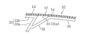
上記エアバッグユニット21は、上記段差部1b近傍における上記上面後側部1dのインストルメントパネル1内側に、ケース22の開口部が上方に向かって車両後方に傾斜する方向を向くように配設されている。そして、上記上面後側部1dにおける上記エアバッグユニット21に対応する位置(上記ケース22の開口部と対向する位置)に、該上面後側部1dのインストルメントパネル内側面(内側層1gの外側層1fとは反対側の面)に形成された断面略V字状の破断溝31により区画されてなりかつ上記バッグ体24の展開圧による該破断溝31の破断により開く蓋部32が設けられている。上記破断溝31は、図1に示すように、平面視で略矩形状に形成されており、互いに車両前後方向に対向する2つの長辺部31a,31aと、互いに車幅方向に対向する2つの短辺部31b,31bとからなっている。車両前側の長辺部31aは、上記上面前側部1cの車両後側端と車両前後方向において略同じ位置にある。そして、上記バッグ体24は、上記蓋部32が開くことで形成された開口を通ってインストルメントパネル1の外側に展開するようになされている。尚、インストルメントパネル1の外側面に破断溝は形成されておらず、所謂シームレスの構成とされている。
The
上記上面後側部1dのインストルメントパネル内側面には、上記エアバッグユニット21と蓋部32との間における上記バッグ体24の展開空間を囲む枠部33が固定されている。この枠部33は、サーモプラスチックオレフィンからなっていて、断面が上記蓋部32と略同じ大きさの矩形枠状とされた枠本体部33aと、この枠本体部33aの蓋部32側の端部における外周面全周に設けられた鍔部33bとからなり、この鍔部33bが、上記上面後側部1dのインストルメントパネル内側面に溶着により接合固定されている。上記枠本体部33aは、上記ケース22の開口部が向く方向に延びており、このことで、バッグ体24は、上方に向かって車両後方に傾斜する方向に展開する。したがって、エアバッグユニット21及び枠部33は、バッグ体24が上方に向かって車両後方に傾斜する方向に展開するように配設されていることになる。
A
上記蓋部32のインストルメントパネル内側面には、上記枠部33と同じサーモプラスチックオレフィンからなる裏打板34が溶着により固定されている。この裏打板34と上記枠部33の枠本体部33aの内周面との間には、全周に亘って隙間が形成されている。そして、裏打板34の車両前側端部と、枠本体部33aの内周面における車両前側部分とは、車両側面視で略U字状に曲がった形状に形成されたヒンジ部材35によって連結されている。つまり、蓋部32は、該蓋部32の車両前側端部でヒンジ部材35を介して枠部33に連結されていることになる。このヒンジ部材35も、枠部33及び裏打板34と同様に、サーモプラスチックオレフィンからなっており、本実施形態では、枠部33、裏打板34及びヒンジ部材35は一体成形されてなるものである。尚、枠部33、裏打板34及びヒンジ部材35は、サーモプラスチックオレフィンに限らず、他の材料で構成してもよい。但し、枠部33及び裏打板34は、ポリプロピレン等の硬い材料で構成するのが好ましいが、ヒンジ部材35は、後述の如く変形させたり伸ばしたりするために、サーモプラスチックオレフィンのような軟質材料等で構成する必要がある。
A
上記蓋部32は、上記バッグ体24の展開圧により上記破断溝31が破断しかつ上記ヒンジ部材35を略中心にして車両前側に回動することで開くように構成されている。そして、上記ヒンジ部材35は、上記バッグ体24の最大展開状態で上記蓋部32を上記上面前側部1cの段差部1b側の端(車両後側端)よりも上側に位置させるように構成されている。すなわち、ヒンジ部材35は、バッグ体24の展開圧により蓋部32が回動しているときに、該展開圧により車両側面視で略U字状に曲がった形状からヒンジ部材35の枠部連結部側から蓋部連結部側へ向かう方向に略直線状に延びる形状に変形しかつヒンジ部材35の枠部連結部側から蓋部連結部側へ向かう方向に、弾性変形して又は弾性及び塑性変形して伸びる(ヒンジ部材35の長さが長くなる)ようになっている。そして、バッグ体24の最大展開状態では、ヒンジ部材35の長さが上記段差部1bの高さよりも大きくなるようになっており、このことで、蓋部32は、段差部1b(特に接続部1eの上端部)に当接することなく、段差部1bを乗り越えるように回動し、最終的に蓋部32のインストルメントパネル外側面の略全体、又は蓋部32のヒンジ部材35側の一部が上面前側部1cのインストルメントパネル外側面に接触した状態となる(図3参照)。
The
このように蓋部32が段差部1bに当接しないので、バッグ体24の車両前側部が蓋部32に邪魔されることなく車両前側へ展開して、フロントガラス2とインストルメントパネル1の上面部1aとの間の空間の略全体に展開する(図3参照)。一方、ヒンジ部材35が、変形や伸びが生じない構成である場合には、蓋部32が段差部1bに当接して、それ以上開かなくなる可能性が高くなり、このようになると、バッグ体24の車両前側部が、蓋部32に邪魔されて、車両前側へ展開することができなくなり、バッグ体24の最大展開状態で、バッグ体24の車両前側部とフロントガラス2の車両前側端ないし上面前側部1cの車両前側端との間に隙間が生じる。このため、助手席に着座している乗員が、展開したバッグ体24の車両後側部に衝突したときに、その衝撃力によりバッグ体24全体が上記隙間の分だけ車両前方へ移動し、その移動分だけ乗員を受け止めるのが遅れてしまう。しかし、本実施形態では、乗員がバッグ体24に衝突する前には、バッグ体24の車両前側部がフロントガラス2とインストルメントパネル1の上面部1aとの間の空間の略全体に展開しているので、バッグ体24の車両後側部に乗員が衝突したときに、その衝撃力によりバッグ体全体が車両前方へ移動するようなことはなくて、その衝撃力を確実に受け止めて乗員を適切に保護することができるようになる。また、バッグ体24の展開時等に蓋部32が破損して飛散するようなこともない。
Since the
尚、上記実施形態では、蓋部32の車両前側端(破断溝31の車両前側の長辺部31a)を、上面前側部1cの車両後側端に対して、車両前後方向において略同じ位置になるようにしたが、図4に示すように、蓋部32の車両前側端を上面前側部1cの車両後側端よりも車両前側に位置させるとともに、これに伴ってエアバッグユニット21の配設位置を上記実施形態よりも車両前側へずらすようにしてもよい。このように蓋部32の車両前側端が上面前側部1cの車両後側端よりも車両前側にあっても、枠部33の枠本体部33aが上方に向かって車両後方に傾斜しているので、蓋部32は、その回動初期に、バッグ体24により、上方に向かって車両後方に傾斜する方向に押され、これにより、蓋部32は、段差部1bに当接することなく、段差部1bを乗り越えるように回動することが可能になる。
In the above-described embodiment, the vehicle front side end of the lid portion 32 (the
また、上記実施形態では、ヒンジ部材35を、車両側面視で略U字状に曲がった形状に形成したが、どのような形状に形成してもよい。例えば図5に示すように、車両側面視で略L字状に曲がった形状に形成してもよく、或いは、曲がった形状ではなくて、例えば図5に示すように、当初から、車両側面視でヒンジ部材35の枠部連結部側から蓋部連結部側へ向かう方向に略直線状に延びる(図6では、上方に向かって車両後方に傾斜する方向に延びている)形状に形成してもよい。このようにヒンジ部材35を略直線状に延びる形状に形成した場合、バッグ体24の展開圧により蓋部32が回動しているときに、該展開圧によりヒンジ部材35がその長さ方向に伸びることで、バッグ体24の最大展開状態で蓋部32を上面前側部1cの段差部1b側の端よりも上側に位置させるようにすればよい。
Moreover, in the said embodiment, although the
さらに、上記実施形態では、蓋部32が分割することなく開く構成としたが、例えば蓋部32の車両前後方向中間部に車幅方向に延びる破断溝を形成し、バッグ体24の展開圧により蓋部32が車両前側分割部と後側分割部とに分割する構成(破断溝が平面視でH型になっている構成)としてもよい。この場合、車両前側分割部は、上記実施形態と同様に、蓋部32の車両前側端部で枠部33に連結した第1ヒンジ部材を介して車両前側へ回動する一方、車両後側分割部は、蓋部32の車両後側端部で枠部33に連結した第2ヒンジ部材を介して車両後側へ回動するように構成する。そして、上記第1ヒンジ部材を、上記実施形態のヒンジ部材35と同様の構成にすれば、車両前側分割部が段差部1bに当接することなく、段差部1bを乗り越えるように回動することになる。
Furthermore, in the said embodiment, it was set as the structure which opens the lid | cover
また、本発明は、特開2005−247245号公報に記載されているように、上面前側部を上下移動させて、段差部がある状態と、段差部がないフラットな状態とを切換え可能としたものにおいて、段差部がある状態のときにエアバッグユニットを作動させる場合にも適用することができる。 In addition, as described in Japanese Patent Application Laid-Open No. 2005-247245, the present invention makes it possible to switch between a state where there is a stepped portion and a flat state where there is no stepped portion by moving the upper front side portion up and down. In the thing, it is applicable also when operating an airbag unit in the state with a level | step-difference part.
本発明は、エアバッグユニットを備えたインストルメントパネルに有用であり、特にインストルメントパネルにおけるフロントガラス下側に位置する上面部の車両前後方向中間部に段差部が形成されたものに有用である。 INDUSTRIAL APPLICABILITY The present invention is useful for an instrument panel provided with an airbag unit, and particularly useful for an instrument panel in which a step portion is formed in the vehicle front-rear direction intermediate portion of the upper surface portion located below the windshield. .
1 インストルメントパネル
1a 上面部
1b 段差部
1c 上面前側部
1d 上面後側部
2 フロントガラス
21 エアバッグユニット
24 バッグ体
31 破断溝
32 蓋部
33 枠部
35 ヒンジ部材
DESCRIPTION OF
Claims (6)
上記インストルメントパネルにおけるフロントガラス下側に位置する上面部の車両前後方向中間部に段差部が形成されて、該上面部において該段差部の車両後側に位置する上面後側部が、段差部の車両前側に位置する上面前側部よりも下側に位置しており、
上記エアバッグユニットは、展開するバッグ体を有していて、上記段差部近傍における上記上面後側部のインストルメントパネル内側に配設され、
上記上面後側部における上記エアバッグユニットに対応する位置に、該上面後側部のインストルメントパネル内側面に形成された破断溝により区画されてなりかつ上記バッグ体の展開圧による該破断溝の破断により開く蓋部が設けられ、
上記バッグ体は、上記蓋部が開くことで形成された開口を通ってインストルメントパネル外側に展開するように構成され、
上記上面後側部のインストルメントパネル内側面に、上記エアバッグユニットと蓋部との間における上記バッグ体の展開空間を囲む枠部が固定され、
上記蓋部は、該蓋部の車両前側端部でヒンジ部材を介して上記枠部に連結されていて、上記バッグ体の展開圧により上記破断溝が破断しかつ該ヒンジ部材を略中心にして車両前側に回動することで開くように構成され、
上記ヒンジ部材は、上記バッグ体の最大展開状態で上記蓋部を上記上面前側部の段差部側の端よりも上側に位置させるように構成されていることを特徴とするエアバッグユニットを備えたインストルメントパネル構造。 An instrument panel structure provided with an airbag unit provided at a front end portion of a vehicle interior of a vehicle,
In the instrument panel, a step portion is formed at a vehicle front-rear direction intermediate portion of the upper surface portion located below the windshield, and the upper surface rear side portion located on the vehicle rear side of the step portion is the step portion. Is located below the front side of the upper surface located on the front side of the vehicle,
The airbag unit has a bag body that is deployed, and is disposed inside the instrument panel on the rear side of the upper surface in the vicinity of the stepped portion,
In the position corresponding to the airbag unit on the rear side of the upper surface, it is partitioned by the fracture groove formed on the inner surface of the instrument panel on the rear side of the upper surface, and the fracture groove by the deployment pressure of the bag body A lid that opens by breaking is provided,
The bag body is configured to expand to the outside of the instrument panel through an opening formed by opening the lid,
A frame portion that surrounds the deployment space of the bag body between the airbag unit and the lid portion is fixed to the inner surface of the instrument panel on the upper rear side portion,
The lid portion is connected to the frame portion via a hinge member at a vehicle front side end portion of the lid portion, and the breaking groove is broken by the developing pressure of the bag body, and the hinge member is substantially centered. It is configured to open by rotating to the front of the vehicle,
The hinge member includes an airbag unit configured to position the lid portion above an end on the stepped portion side of the upper surface front side portion in a maximum deployed state of the bag body. Instrument panel structure.
ヒンジ部材は、バッグ体の展開圧により蓋部が回動しているときに、該展開圧により車両側面視で曲がった形状から略直線状に延びる形状に変形することで、該バッグ体の最大展開状態で該蓋部を上面前側部の段差部側の端よりも上側に位置させるように構成されていることを特徴とするエアバッグユニットを備えたインストルメントパネル構造。 In the instrument panel structure comprising the airbag unit according to claim 1,
When the lid is rotated by the deployment pressure of the bag body, the hinge member is deformed from a bent shape in a side view of the vehicle to a shape extending substantially linearly by the deployment pressure. An instrument panel structure provided with an airbag unit, wherein the lid is configured to be positioned above the end of the stepped portion side of the top front side portion in the deployed state.
ヒンジ部材は、車両側面視で略U字状に曲がった形状に形成されていることを特徴とするエアバッグユニットを備えたインストルメントパネル構造。 In the instrument panel structure comprising the airbag unit according to claim 2,
An instrument panel structure provided with an airbag unit, wherein the hinge member is formed in a substantially U-shaped shape when viewed from the side of the vehicle.
ヒンジ部材は、バッグ体の展開圧により蓋部が回動しているときに、該展開圧により該ヒンジ部材の枠部連結部側から蓋部連結部側へ向かう方向に伸びることで、該バッグ体の最大展開状態で該蓋部を上面前側部の段差部側の端よりも上側に位置させるように構成されていることを特徴とするエアバッグユニットを備えたインストルメントパネル構造。 In the instrument panel structure provided with the airbag unit according to any one of claims 1 to 3,
The hinge member extends in the direction from the frame connecting portion side to the lid connecting portion side of the hinge member by the developing pressure when the lid portion is rotated by the developing pressure of the bag body. An instrument panel structure provided with an airbag unit, wherein the lid portion is positioned above an end of a stepped portion side of the upper surface front side portion when the body is fully deployed.
ヒンジ部材は、サーモプラスチックオレフィンからなることを特徴とするエアバッグユニットを備えたインストルメントパネル構造。 In the instrument panel structure provided with the airbag unit according to any one of claims 2 to 4,
An instrument panel structure provided with an airbag unit, wherein the hinge member is made of a thermoplastic olefin.
エアバッグユニット及び枠部は、バッグ体が上方に向かって車両後方に傾斜する方向に展開するように配設されていることを特徴とするエアバッグユニットを備えたインストルメントパネル構造。 In the instrument panel structure provided with the airbag unit according to any one of claims 1 to 5,
An instrument panel structure provided with an airbag unit, wherein the airbag unit and the frame portion are arranged so that the bag body is deployed in a direction in which the airbag body inclines upward toward the rear of the vehicle.
Priority Applications (5)
| Application Number | Priority Date | Filing Date | Title |
|---|---|---|---|
| JP2005370640A JP4670629B2 (en) | 2005-12-22 | 2005-12-22 | Instrument panel structure with airbag unit |
| DE602006012430T DE602006012430D1 (en) | 2005-12-22 | 2006-11-21 | Dashboard with passenger airbag |
| EP06024152A EP1800971B1 (en) | 2005-12-22 | 2006-11-21 | Instrument dashboard panel structure with passenger airbag unit |
| US11/635,493 US7658404B2 (en) | 2005-12-22 | 2006-12-08 | Instrument panel structure with airbag unit |
| CN2006101659806A CN1986293B (en) | 2005-12-22 | 2006-12-12 | Instrument dashboard panel structure with passenger airbag unit |
Applications Claiming Priority (1)
| Application Number | Priority Date | Filing Date | Title |
|---|---|---|---|
| JP2005370640A JP4670629B2 (en) | 2005-12-22 | 2005-12-22 | Instrument panel structure with airbag unit |
Publications (2)
| Publication Number | Publication Date |
|---|---|
| JP2007168666A JP2007168666A (en) | 2007-07-05 |
| JP4670629B2 true JP4670629B2 (en) | 2011-04-13 |
Family
ID=37693785
Family Applications (1)
| Application Number | Title | Priority Date | Filing Date |
|---|---|---|---|
| JP2005370640A Expired - Fee Related JP4670629B2 (en) | 2005-12-22 | 2005-12-22 | Instrument panel structure with airbag unit |
Country Status (5)
| Country | Link |
|---|---|
| US (1) | US7658404B2 (en) |
| EP (1) | EP1800971B1 (en) |
| JP (1) | JP4670629B2 (en) |
| CN (1) | CN1986293B (en) |
| DE (1) | DE602006012430D1 (en) |
Families Citing this family (18)
| Publication number | Priority date | Publication date | Assignee | Title |
|---|---|---|---|---|
| DE102004009914A1 (en) * | 2004-02-20 | 2005-10-06 | Daimlerchrysler Ag | Airbag cover for an airbag of a motor vehicle |
| US7793972B2 (en) * | 2007-03-14 | 2010-09-14 | Nissan Technical Center North America, Inc. | Front pillar trim panel with tether |
| JP5046777B2 (en) * | 2007-07-30 | 2012-10-10 | タカタ株式会社 | Airbag device |
| JP2009040328A (en) * | 2007-08-10 | 2009-02-26 | Toyoda Gosei Co Ltd | Side airbag device |
| JP5050731B2 (en) * | 2007-08-23 | 2012-10-17 | トヨタ紡織株式会社 | Groove formation method |
| FR2925410B1 (en) * | 2007-12-21 | 2010-05-14 | Faurecia Interieur Ind | ADVANCED DASHBOARD |
| KR101071733B1 (en) * | 2008-12-01 | 2011-10-11 | 기아자동차주식회사 | Air-bag apparatus for vehicles |
| ES2350414T3 (en) * | 2008-12-05 | 2011-01-21 | Peguform Gmbh | MODULARLY STRUCTURED INTERIOR COATING COMPONENT WITH A TRIGGER CHANNEL MODULE FOR AN AIRBAG. |
| US8181987B2 (en) * | 2010-06-27 | 2012-05-22 | Ford Global Technologies, Llc | Air bag deployment door with force transmitting hinge |
| KR101240603B1 (en) * | 2010-11-22 | 2013-03-06 | 현대모비스 주식회사 | Passenger air bag door |
| CN102069771A (en) * | 2010-12-31 | 2011-05-25 | 常州新泉汽车内饰件有限公司 | Air bag bracket for passengers |
| EP2543553B1 (en) * | 2011-07-07 | 2015-03-04 | Zodiac Seats France | Pneumatic and mechanical energy absorber |
| DE102012001214A1 (en) * | 2012-01-21 | 2013-07-25 | GM Global Technology Operations LLC (n. d. Gesetzen des Staates Delaware) | Vehicle interior panel has dividing line that is arranged partially in stepped root of stepped airbag cover and/or primary and secondary flaps |
| FR2991941B1 (en) * | 2012-06-15 | 2015-07-03 | Faurecia Interieur Ind | DEVICE FOR CLOSING AN INFLATABLE CUSHION MODULE COMPRISING A VARIABLE LENGTH HINGE AREA |
| JP5765314B2 (en) * | 2012-09-28 | 2015-08-19 | トヨタ自動車株式会社 | Airbag device for passenger seat |
| CN103419739B (en) * | 2013-02-01 | 2016-12-28 | 上海延锋金桥汽车饰件系统有限公司 | A kind of metal air bag door system |
| EP3514020B1 (en) * | 2018-01-22 | 2021-06-30 | Motherson Innovations Company Limited | Air bag guiding device for guiding a vehicle airbag, airbag unit with such an airbag guide and internal cladding component and method for producing a corresponding internal cladding component, comprising such an airbag guide |
| WO2020205687A1 (en) * | 2019-03-29 | 2020-10-08 | Mcpp Innovation Llc | All tpo airbag assemblies |
Citations (3)
| Publication number | Priority date | Publication date | Assignee | Title |
|---|---|---|---|---|
| JP2004249876A (en) * | 2003-02-21 | 2004-09-09 | Shigeru Co Ltd | Air bag lid structure |
| JP2005014747A (en) * | 2003-06-25 | 2005-01-20 | Nippon Plast Co Ltd | Cover of air bag device and air bag device |
| JP2005335594A (en) * | 2004-05-27 | 2005-12-08 | Nippon Plast Co Ltd | Cover of airbag device and its manufacturing method |
Family Cites Families (22)
| Publication number | Priority date | Publication date | Assignee | Title |
|---|---|---|---|---|
| US4893833A (en) * | 1988-09-08 | 1990-01-16 | Tip Engineering Group, Inc. | Closure for an air bag deployment opening |
| JPH06135294A (en) * | 1992-10-29 | 1994-05-17 | Mazda Motor Corp | Air bag structure for automobile |
| US5460401A (en) * | 1994-08-05 | 1995-10-24 | Morton International, Inc. | Airbag system with tethered cover |
| US6053527A (en) * | 1994-08-05 | 2000-04-25 | Autoliv Asp, Inc. | Airbag system with serviceable tethered cover |
| DE4437773C1 (en) * | 1994-10-24 | 1995-10-26 | Daimler Benz Ag | Instrument panel with an integrated, hinged gas bag cover |
| EP0748722B1 (en) * | 1995-06-16 | 2001-09-12 | Toyoda Gosei Co., Ltd. | Interior finish member for an automobile with an air bag device and manufacturing method thereof |
| JPH10244898A (en) * | 1997-03-06 | 1998-09-14 | Toyota Motor Corp | Air bag door structure |
| US6457738B1 (en) * | 1997-06-09 | 2002-10-01 | Textron Automotive Company, Inc. | Inflatable restraint apparatus |
| US6955376B1 (en) * | 1997-06-09 | 2005-10-18 | Collins & Aikman Products Co. | Apparatus for deploying an air bag through a hard panel |
| JP2998745B2 (en) * | 1997-10-09 | 2000-01-11 | トヨタ自動車株式会社 | Instrument panel with integrated airbag door |
| JP3309178B2 (en) * | 1998-01-19 | 2002-07-29 | 三光合成株式会社 | Airbag device for passenger seat |
| FR2776974B1 (en) * | 1998-04-03 | 2000-06-16 | Ecia Equip Composants Ind Auto | MOTOR VEHICLE EQUIPMENT PART WITH INFLATABLE BAG MODULE |
| DE19940984A1 (en) * | 1999-08-28 | 2001-03-22 | Opel Adam Ag | Mounting table for airbag module, has single piece component secured to it comprising hinge plate and airbag firing channel sections |
| FR2809692A1 (en) * | 2000-05-31 | 2001-12-07 | Ecia Equip Composants Ind Auto | Cover assembly for vehicle air bag, has rigid structural element with line of reduced resistance to outline flap, and form rupture line and hinge, formed by flexible layer stuck on to structural layer |
| FR2811952B1 (en) * | 2000-07-18 | 2003-01-31 | Ecia Equip Composants Ind Auto | MOTOR VEHICLE EQUIPMENT FOR INFLATABLE BAG, ASSEMBLY THEREOF AND MANUFACTURING METHOD THEREOF |
| KR100353055B1 (en) * | 2000-09-01 | 2002-09-18 | 현대자동차주식회사 | Airbag door for automobile |
| JP3973029B2 (en) * | 2002-03-28 | 2007-09-05 | 三光合成株式会社 | Airbag device for automobile |
| US7093849B2 (en) * | 2002-09-24 | 2006-08-22 | Nihon Plast Co., Ltd. | Cover body for air bag apparatus |
| DE60307198T2 (en) * | 2002-10-15 | 2007-07-19 | Nishikawa Kasei Co. Ltd. | Airbag cover for a vehicle |
| JP2005088634A (en) | 2003-09-12 | 2005-04-07 | Nishikawa Kasei Co Ltd | Vehicle interior trim with airbag door part |
| DE10359751B4 (en) * | 2003-12-19 | 2008-07-10 | Dr.Ing.H.C. F. Porsche Ag | Instrument panel with a passenger airbag |
| JP2005247245A (en) | 2004-03-08 | 2005-09-15 | Honda Motor Co Ltd | Vehicle body front part structure |
-
2005
- 2005-12-22 JP JP2005370640A patent/JP4670629B2/en not_active Expired - Fee Related
-
2006
- 2006-11-21 DE DE602006012430T patent/DE602006012430D1/en active Active
- 2006-11-21 EP EP06024152A patent/EP1800971B1/en not_active Ceased
- 2006-12-08 US US11/635,493 patent/US7658404B2/en not_active Expired - Fee Related
- 2006-12-12 CN CN2006101659806A patent/CN1986293B/en not_active Expired - Fee Related
Patent Citations (3)
| Publication number | Priority date | Publication date | Assignee | Title |
|---|---|---|---|---|
| JP2004249876A (en) * | 2003-02-21 | 2004-09-09 | Shigeru Co Ltd | Air bag lid structure |
| JP2005014747A (en) * | 2003-06-25 | 2005-01-20 | Nippon Plast Co Ltd | Cover of air bag device and air bag device |
| JP2005335594A (en) * | 2004-05-27 | 2005-12-08 | Nippon Plast Co Ltd | Cover of airbag device and its manufacturing method |
Also Published As
| Publication number | Publication date |
|---|---|
| CN1986293A (en) | 2007-06-27 |
| US20070145728A1 (en) | 2007-06-28 |
| EP1800971A1 (en) | 2007-06-27 |
| CN1986293B (en) | 2012-05-30 |
| EP1800971B1 (en) | 2010-02-24 |
| DE602006012430D1 (en) | 2010-04-08 |
| US7658404B2 (en) | 2010-02-09 |
| JP2007168666A (en) | 2007-07-05 |
Similar Documents
| Publication | Publication Date | Title |
|---|---|---|
| JP4670629B2 (en) | Instrument panel structure with airbag unit | |
| JP4446901B2 (en) | Cover for airbag device and airbag device | |
| JP2008143502A (en) | Vehicular front passenger seat airbag door | |
| JP2006205889A5 (en) | ||
| JP4057880B2 (en) | Airbag door for vehicle | |
| JP2004161182A (en) | Supporting structure of airbag door | |
| KR101606477B1 (en) | Air bag door for vehicles | |
| JP4093847B2 (en) | Cover body of airbag device | |
| JP4379766B2 (en) | Cover body of airbag device | |
| JP4242215B2 (en) | Cover for airbag device and airbag device | |
| JP4762677B2 (en) | Airbag device cover | |
| JP4901182B2 (en) | Airbag device cover | |
| JP5209449B2 (en) | Interior parts for vehicles with airbag doors | |
| JP3926624B2 (en) | Cover body of airbag device | |
| JP2007302209A (en) | Airbag structure | |
| JP2006062422A (en) | Airbag door | |
| JP4113791B2 (en) | Airbag door for vehicle | |
| JP4955495B2 (en) | Airbag device | |
| JP3787517B2 (en) | Interior parts for vehicles with airbag doors | |
| JP4229229B2 (en) | instrument panel | |
| JP3892789B2 (en) | Automotive airbag equipment | |
| JP2003205813A (en) | Interior parts for vehicle with air bag door | |
| JP2003200807A (en) | Cover for air bag device | |
| JP2024076210A (en) | Air bag door and vehicular interior panel | |
| JP2002187516A (en) | Air bag door for front passenger seat of vehicle |
Legal Events
| Date | Code | Title | Description |
|---|---|---|---|
| A621 | Written request for application examination |
Free format text: JAPANESE INTERMEDIATE CODE: A621 Effective date: 20081118 |
|
| A977 | Report on retrieval |
Free format text: JAPANESE INTERMEDIATE CODE: A971007 Effective date: 20101216 |
|
| TRDD | Decision of grant or rejection written | ||
| A01 | Written decision to grant a patent or to grant a registration (utility model) |
Free format text: JAPANESE INTERMEDIATE CODE: A01 Effective date: 20101221 |
|
| A01 | Written decision to grant a patent or to grant a registration (utility model) |
Free format text: JAPANESE INTERMEDIATE CODE: A01 |
|
| A61 | First payment of annual fees (during grant procedure) |
Free format text: JAPANESE INTERMEDIATE CODE: A61 Effective date: 20110103 |
|
| R150 | Certificate of patent or registration of utility model |
Ref document number: 4670629 Country of ref document: JP Free format text: JAPANESE INTERMEDIATE CODE: R150 Free format text: JAPANESE INTERMEDIATE CODE: R150 |
|
| FPAY | Renewal fee payment (event date is renewal date of database) |
Free format text: PAYMENT UNTIL: 20140128 Year of fee payment: 3 |
|
| LAPS | Cancellation because of no payment of annual fees |