JP4635794B2 - Inkjet recording device - Google Patents
Inkjet recording device Download PDFInfo
- Publication number
- JP4635794B2 JP4635794B2 JP2005269926A JP2005269926A JP4635794B2 JP 4635794 B2 JP4635794 B2 JP 4635794B2 JP 2005269926 A JP2005269926 A JP 2005269926A JP 2005269926 A JP2005269926 A JP 2005269926A JP 4635794 B2 JP4635794 B2 JP 4635794B2
- Authority
- JP
- Japan
- Prior art keywords
- nozzle
- wiper member
- wiper
- wiping
- ink
- Prior art date
- Legal status (The legal status is an assumption and is not a legal conclusion. Google has not performed a legal analysis and makes no representation as to the accuracy of the status listed.)
- Expired - Fee Related
Links
Images


Landscapes
- Ink Jet (AREA)
Description
本発明は、インクジェット記録装置に関するものである。 The present invention relates to an ink jet recording apparatus.
従来より、記録用紙(記録媒体)を記録ヘッドに対して相対的に移動させ、前記記録ヘッドをキャリッジ上で記録用紙の幅方向に移動させながら記録用紙に対してインク滴を吐出させることで記録を行うインクジェット記録装置は知られている。 Conventionally, recording paper (recording medium) is moved relative to the recording head, and recording is performed by ejecting ink droplets onto the recording paper while moving the recording head in the width direction of the recording paper on the carriage. Inkjet recording apparatuses that perform the above are known.
そのような記録ヘッドは、ノズルからインク滴として記録用紙に吐出させて記録を行う関係上、ノズルの吐出口からのインクの蒸発に起因するインク粘度の上昇や、インクの固化、塵埃の付着、さらには気泡の混入などによりノズルの吐出口に目詰まりし、記録不良を起こすおそれがある。 Since such a recording head performs recording by ejecting ink droplets from a nozzle onto a recording sheet, ink viscosity increases due to evaporation of ink from the nozzle ejection port, ink solidification, dust adhesion, Furthermore, there is a risk of clogging of the nozzle outlet due to air bubbles and the like, resulting in recording failure.
そのために、インクジェット記録装置は、非記録時に記録ヘッドのノズル面をキャップ部材にて覆うキャップ手段と、必要に応じて記録ヘッドのノズル面をワイパー部材の払拭動作にて清掃するワイパー手段を備えているのが一般的である。 Therefore, the ink jet recording apparatus includes a cap unit that covers the nozzle surface of the recording head with a cap member during non-recording, and a wiper unit that cleans the nozzle surface of the recording head by a wiping operation of the wiper member as necessary. It is common.
そして、そのようなインクジェット記録装置においては、キャップ部材にて前記ノズル面を覆った状態でノズルのインクを吸引し、その後に、ワイパー部材により前記ノズル面を払拭して、残インクを除去する操作が行われる。 In such an ink jet recording apparatus, the nozzle surface is sucked with the cap member covered by the cap member, and then the nozzle surface is wiped by the wiper member to remove residual ink. Is done.
すなわち、このワイパー手段は、ノズル面に残留したインクを払拭するためのものであり、ノズル面に残留したインクが乾燥してノズルが詰まるという不具合を解消するために用いられていた。 That is, the wiper means is for wiping off ink remaining on the nozzle surface, and has been used to solve the problem that the ink remaining on the nozzle surface dries and the nozzle is clogged.
そのようなインクジェット記録装置において、キャップ部材にワイパー部材を配置し、ワイパー部材によって払拭したインクを効果的に回収し、ワイパー部材から滴下するインク廃液によってもたらされる汚染、および機器の駆動障害の発生を防止するようにしたものが提案されている(例えば、特許文献1参照)。
ところで、ノズル面を覆うキャップはゴム材料で形成されているが、ゴム材料がインクと接触することによって析出した物質が、インクジェット記録装置に対して悪影響を及ぼす場合があることが、発明者の研究によりわかってきた。 By the way, the cap that covers the nozzle surface is made of a rubber material. However, the inventors have studied that substances deposited when the rubber material comes into contact with ink may adversely affect the ink jet recording apparatus. It has been understood.
すなわち、発明者の知見したところによると、インクジェット記録に用いるインクと直接的あるいは間接的に接触する部位に関しては、インクとの接触による材料の化学変化が生じやすく、きわめて慎重な材料選定が必要であり、その中でも、特にゴム材料においては、インクと所定の時間接触すると、ゴムの製造工程で添加される加硫化剤やその他反応助剤などがノズル面に析出または堆積し、ゴム特性の劣化やインク物性への影響から記録品質の劣化、更にはインクジェット装置としての全体の動作を著しく妨げる可能性が懸念されている。 That is, according to the inventor's knowledge, regarding the portion that directly or indirectly contacts the ink used for ink jet recording, chemical change of the material is likely to occur due to contact with the ink, and it is necessary to select a very careful material. Among them, particularly in rubber materials, when contacted with ink for a predetermined period of time, vulcanizing agents and other reaction aids added in the rubber production process are deposited or deposited on the nozzle surface, resulting in deterioration of rubber properties. There is a concern that the recording quality may be deteriorated due to the influence on the physical properties of the ink, and the entire operation of the ink jet apparatus may be significantly hindered.
具体的には、記録ヘッドのノズル面をキャップ部材で覆うキャップ手段や、ノズル面のインク液滴をワイパー部材にて払拭するワイパー手段においてはゴム材料が多く使用されているので、キャップ部材やワイパー部材に生じた異物(例えば析出物質)が、ワイパー部材の払拭動作によりノズル内への進入したり外周に付着したりして、インクの吐出安定性に大きな影響を与える可能性がある。特に、キャップ部材との接触部分とノズルの吐出口とが同一平面上に配置されている場合、キャップ部材との接触部分で生じた析出物質などの異物がノズル内に侵入すると、インク吐出不良やインク液滴吐出の直進性などを損なうことになり、長期にわたって安定したインクジェット吐出特性を保持することができなくなる可能性がある。 Specifically, a rubber material is often used in the cap means for covering the nozzle surface of the recording head with the cap member and the wiper means for wiping ink droplets on the nozzle surface with the wiper member. There is a possibility that foreign matters (for example, deposited substances) generated on the member may enter the nozzle or adhere to the outer periphery due to the wiping operation of the wiper member, greatly affecting the ink ejection stability. In particular, when the contact portion with the cap member and the discharge port of the nozzle are arranged on the same plane, if foreign matter such as a deposited substance generated at the contact portion with the cap member enters the nozzle, ink discharge failure or This may impair the straightness of ink droplet ejection, and may not be able to maintain stable inkjet ejection characteristics over a long period of time.
しかしながら、従来のワイパー手段は、ノズルの吐出口を含むノズル面を払拭するものであることから、異物がノズル内に押し込まれる可能性があり、上記の問題点の解決には適していなかった。また、特許文献1に記載されたワイパー部材は、ノズル面におけるキャップとの接触部分を払拭するものではないため、ワイパー部材によって異物がノズル内に押し込まれる可能性は少ないが、異物はノズル面に残留したままとなるためノズル内に侵入する危険性を有していた。
However, since the conventional wiper means wipes the nozzle surface including the nozzle outlet, foreign matter may be pushed into the nozzle and is not suitable for solving the above-described problems. Moreover, since the wiper member described in
この発明は、キャップ部材と記録ヘッドのノズル面の接触部分に生じる析出物質などの異物によるノズルの吐出口の目詰まりを回避して、長期にわたり安定したインク吐出特性を維持することができるインクジェット記録装置を提供することを目的とする。 The present invention avoids clogging of the nozzle ejection port due to foreign matters such as precipitates generated at the contact portion between the cap member and the nozzle surface of the recording head, and can maintain stable ink ejection characteristics over a long period of time. An object is to provide an apparatus.
請求項1の発明は、複数のノズルのインク吐出口が設けられたノズル領域面と、前記ノズル領域面より後退した後退面と、前記ノズル領域面と前記後退面をつなぐ段差部からなるノズル面を有し、前記複数のノズルから記録媒体に対してインクを吐出する記録ヘッドと、前記ノズル面の前記後退面に当接して前記ノズル面を覆い前記ノズル面の前面の空間を密閉するキャップ部材を備えたキャップ手段と、前記ノズル面に接離可能なワイパー部材を有し、前記記録ヘッドに対して前記ワイパー部材が相対移動することにより前記ノズル面を払拭するワイパー手段とを備えたインクジェット記録装置において、前記ワイパー部材の払拭開始側に位置する前記段差部に、異物の溜まり部が形成されており、前記ワイパー手段は、前記後退面の前記キャップ部材が当接した部分を払拭した後に、前記ノズル領域面を払拭することを特徴とする。 According to a first aspect of the present invention, there is provided a nozzle surface comprising a nozzle region surface provided with ink discharge ports of a plurality of nozzles, a receding surface retreated from the nozzle region surface, and a step portion connecting the nozzle region surface and the receding surface. anda recording head for ejecting ink to a recording medium from the plurality of nozzles, a cap member for sealing the front surface space of the nozzle surface to cover the nozzle surface in contact with said retraction plane of the nozzle face a cap means having a having a detachably wiper member to the nozzle surface, the ink-jet recording in which the wiper member relative to said recording head and a wiper means for wiping said nozzle surface by relative movement in the device, the stepped portion located in the wiping start side of the wiper member, reservoir are formed of a different material, said wiper means, the said retraction plane After the cap member is dispelled contact portion, characterized by wiping the nozzle region surface.
このようにすれば、ワイパー部材の払拭開始側に位置する段差部に、析出物質やインクミストなどの異物の溜まり部が形成されているので、ノズル領域面の払拭動作に先立って、ワイパー部材が後退面を払拭した際に前記ワイパー部材によって捕捉された異物(キャップ部材と記録ヘッドのノズル面の接触部分に生じる析出物質など)が、前記異物の溜まり部に捕集される。よって、前記異物が、ワイパー部材と一緒に、ノズル領域面内へ持ち込まれるのが回避される。 In this way, since the accumulation portion of foreign substances such as deposited substances and ink mist is formed in the stepped portion located on the wiping start side of the wiper member, the wiper member is moved prior to the wiping operation of the nozzle area surface. Foreign matter captured by the wiper member when the receding surface is wiped (such as a deposited substance generated at the contact portion between the cap member and the nozzle surface of the recording head) is collected in the foreign matter reservoir. Therefore, it is avoided that the foreign matter is brought into the nozzle region surface together with the wiper member.
このように、前述したところの異物をワイパー部材によってノズル領域面内に持ち込まれるのが防止されるので、ノズルの吐出口の目詰まりを回避して、長期にわたり安定したインク吐出特性を維持することが可能となる。 As described above, since the foreign matter described above is prevented from being brought into the nozzle region surface by the wiper member, clogging of the nozzle outlet is avoided, and stable ink ejection characteristics are maintained over a long period of time. Is possible.
請求項2の発明は、請求項1のインクジェット記録装置において、前記異物の溜まり部が、前記後退面と前記後退面に対し鋭角をなして連続する第1の傾斜面とで形成されるくさび形状の溝部であることを特徴とする。 According to a second aspect of the present invention, in the ink jet recording apparatus according to the first aspect, a wedge shape in which the foreign matter reservoir is formed by the receding surface and a first inclined surface that is continuous with an acute angle with respect to the receding surface. It is the groove part of this.
このようにすれば、異物の溜まり部が、くさび形状の溝部として簡単に形成される。また、くさび形状の溝部であるので、析出物質やインクミストなどが混合している異物が毛細管現象により溜まりやすくなる。 In this way, the foreign substance reservoir is easily formed as a wedge-shaped groove. In addition, since the groove is a wedge-shaped groove, foreign matter mixed with precipitates, ink mist, and the like is likely to accumulate due to capillary action.
請求項3の発明は、請求項2のインクジェット記録装置において、前記ノズル領域面が、前記ワイパー部材の払拭開始側に、前記ノズル領域面に対し鋭角をなす第2の傾斜面が連続していることを特徴とする。 According to a third aspect of the present invention, in the ink jet recording apparatus of the second aspect, the second inclined surface that forms an acute angle with respect to the nozzle region surface is continuous with the nozzle region surface on the wiping start side of the wiper member. It is characterized by that.
このようにすれば、ノズル領域面に対し鋭角をなす第2の傾斜面が連続していることで形成される前記鋭角部分で、後退面においてワイパー部材によって払拭された異物を、ノズル領域面への進入に先立って前記ワイパー部材から効果的に掻き取られる。 In this way, the foreign matter wiped off by the wiper member on the receding surface at the acute angle portion formed by the second inclined surface forming an acute angle with respect to the nozzle region surface is continued to the nozzle region surface. Is effectively scraped off from the wiper member prior to entering.
請求項4の発明は、請求項1〜3のいずれかのインクジェット記録装置において、前記ワイパー部材の払拭開始側に位置する前記段差部が、前記ノズル面に直交する方向から見て、上縁部分が前記ワイパー部材の相対移動方向に対し傾斜した直線状に形成されていることを特徴とする。ここで、上縁部分は、ノズル領域面の(ワイパー部材の払拭開始側の)外縁を形成する直線状の部分である。 According to a fourth aspect of the present invention, in the ink jet recording apparatus according to any one of the first to third aspects, the stepped portion positioned on the wiping start side of the wiper member is an upper edge portion as viewed from a direction orthogonal to the nozzle surface. Is formed in a linear shape inclined with respect to the relative movement direction of the wiper member. Here, the upper edge portion is a linear portion that forms the outer edge (on the wiping start side of the wiper member) of the nozzle region surface.
このようにすれば、ワイパー部材の払拭開始側に位置する段差部は、ノズル面に直交する方向から見て、上縁部分が前記ワイパー部材の相対移動方向に対し傾斜した直線状に形成されているので、ワイパー部材の払拭動作の際には、その傾斜した直線状の部分が延びる方向に、掻き取られた異物が案内される。このように、異物の溜まり部の一方の側(記録ヘッドの片側)に異物を集積させることができ、異物の長期的な滞留を回避する上で有利となる。 In this way, the step portion located on the wiping start side of the wiper member is formed in a straight line with the upper edge portion inclined with respect to the relative movement direction of the wiper member when viewed from the direction perpendicular to the nozzle surface. Therefore, during the wiping operation of the wiper member, the scraped foreign matter is guided in the direction in which the inclined linear portion extends. In this way, the foreign matter can be accumulated on one side of the foreign matter reservoir (one side of the recording head), which is advantageous in avoiding long-term retention of the foreign matter.
請求項5の発明は、請求項2〜4のいずれかのインクジェット記録装置において、前記第1の傾斜面が、前記ノズル面に直交する方向から見て、前記ワイパー部材の相対移動方向に対し傾斜して形成され、前記異物の溜まり部の深さが、前記ワイパー部材の払拭方向前側になるほど徐々に深くなっていることを特徴とする。 According to a fifth aspect of the present invention, in the ink jet recording apparatus according to any one of the second to fourth aspects, the first inclined surface is inclined with respect to a relative movement direction of the wiper member when viewed from a direction orthogonal to the nozzle surface. The depth of the foreign substance accumulation portion is gradually increased toward the front side of the wiper member in the wiping direction.
このようにすれば、第1の傾斜面が、ノズル面に直交する方向から見て、前記ワイパー部材の相対移動方向に対し傾斜して形成され、前記異物の溜まり部の深さが、前記ワイパー部材の払拭方向前側になるほど徐々に深くなっているので、前記異物の溜まり部の深さが案内される方向に沿って徐々に深くなっていくことになり、異物が余裕をもって溜められるようになる。 In this case, the first inclined surface is formed so as to be inclined with respect to the relative movement direction of the wiper member when viewed from the direction orthogonal to the nozzle surface, and the depth of the foreign substance reservoir portion is determined by the wiper. Since the depth is gradually increased toward the front side of the wiping direction of the member, the depth of the foreign matter accumulation portion gradually increases along the guided direction, and the foreign matter can be collected with a margin. .
請求項6の発明は、請求項1〜5のいずれかのインクジェット記録装置において、前記ノズル領域面が、ワイパー部材の払拭終了側に、前記ノズル領域面に対し直角あるいは鈍角をなす第3の傾斜面が連続していることを特徴とする。 A sixth aspect of the present invention is the ink jet recording apparatus according to any one of the first to fifth aspects, wherein the nozzle area surface has a third inclination that forms a right angle or an obtuse angle with respect to the nozzle area surface on the wiping end side of the wiper member. The surface is continuous.
このようにすれば、ワイパー部材の払拭終了側に、前記ノズル領域面に対し直角あるいは鈍角をなす第3の傾斜面が連続しているので、キャップ部材がノズル領域面に接触することがなくなり、その接触により生ずる析出物質などの異物による影響を低減する上で有利となる。また、特に、鈍角をなす第3の傾斜面とすれば、ワイパー部材がノズル領域面の払拭を終了して、ノズル領域面から離れる際に、ワイパー部材があまり大きく変形しなくなるので、インクの飛散などが少なくなり、隣接する別のノズルの吐出口への影響が低減される。 In this way, since the third inclined surface that forms a right angle or an obtuse angle with respect to the nozzle region surface is continuous on the wiping end side of the wiper member, the cap member does not contact the nozzle region surface, This is advantageous in reducing the influence of foreign substances such as precipitates produced by the contact. In particular, if the third inclined surface having an obtuse angle is used, the wiper member does not deform so much when the wiper member finishes wiping off the nozzle region surface and leaves the nozzle region surface. And the influence on the discharge port of another adjacent nozzle is reduced.
請求項7の発明は、請求項1〜6のいずれかのインクジェット記録装置において、前記記録ヘッドとワイパー部材との相対移動速度を制御する速度制御手段を備え、前記速度制御手段が、前記ワイパー部材が前記ノズル領域面を払拭するときよりも前記段差部を横切るときの前記相対移動速度を低下させる構成とされていることを特徴とする。 A seventh aspect of the invention is the ink jet recording apparatus according to any one of the first to sixth aspects, further comprising speed control means for controlling a relative moving speed between the recording head and the wiper member, wherein the speed control means is the wiper member. Is configured to reduce the relative movement speed when crossing the stepped portion than when wiping the nozzle area surface.
このようにすれば、ワイパー部材の速度制御により、ワイパー部材によって後退面で払拭された異物が、ノズル領域面への進入に先立って、段差部の部位で前記ワイパー部材から無理なく掻き取られ、異物の溜まり部に溜められる。 In this way, by the speed control of the wiper member, the foreign matter wiped on the receding surface by the wiper member is scraped off from the wiper member at the stepped portion before entering the nozzle region surface. It is collected in the foreign substance reservoir.
請求項8の発明は、請求項1〜7のいずれかのインクジェット記録装置において、前記ワイパー部材が、可撓性を有する平板形状で、前記第1の傾斜面とは反対側に傾斜した状態で支持されていることを特徴とする。 According to an eighth aspect of the present invention, in the ink jet recording apparatus according to any one of the first to seventh aspects, the wiper member has a flexible flat plate shape and is inclined to the side opposite to the first inclined surface. It is characterized by being supported.
このようにすれば、ワイパー部材によって後退面で払拭された異物が、段差部において掻き取られやすくなり、また、ワイパー部材が段差部に引っ掛かって、動作不良が生ずるのが回避される。特に請求項6に記載のように第3の傾斜面が設けられている場合には、ノズル領域面を離れる際のワイパー部材の形状の変化が少なくなり、インクの飛散などが極端に低減される。
In this way, the foreign matter wiped on the receding surface by the wiper member can be easily scraped off at the stepped portion, and the occurrence of malfunction due to the wiper member being caught by the stepped portion can be avoided. In particular, when the third inclined surface is provided as described in
請求項9の発明は、請求項1〜8のいずれかのインクジェット記録装置において、前記後退面が前記ノズル領域面の周囲に形成されると共に前記キャップ部材の開口周縁部が接触する構成とされ、前記後退面には、前記キャップ部材の周縁部が嵌り込む環状溝部が形成されていることを特徴とする。
The invention according to claim 9 is the ink jet recording apparatus according to any one of
このようにすれば、環状溝部が異物(キャップ部材の接触部分に生じる析出物質など)のトラップ効果を有し、ワイパー部材によってノズル領域面に持ち込まれるのを低減する上で有利となる。 In this way, the annular groove portion has a trapping effect of foreign matters (such as precipitates generated at the contact portion of the cap member), which is advantageous in reducing the occurrence of being brought into the nozzle region surface by the wiper member.
以上のように、本発明は、記録ヘッドのノズル面において、ノズルのインク吐出口が設けられたノズル領域面とこのノズル領域面より後退した後退面との間に段差部を設け、この段差部の、前記ワイパー部材の払拭開始側に異物の溜まり部を形成しているので、ワイパー部材が後退面で払拭した異物を、前記異物の溜まり部で捕集して、ノズル領域面に持ち込まれるの回避することができる。よって、そのような異物がノズルの吐出口内へ侵入して目詰まりが生ずるのを防止して、長期にわたり安定したインク吐出特性を維持することが可能となる。 As described above, according to the present invention, on the nozzle surface of the recording head, a step portion is provided between the nozzle region surface where the ink discharge port of the nozzle is provided and the receding surface which is retreated from the nozzle region surface. Since the foreign substance accumulation part is formed on the wiping start side of the wiper member, the foreign substance wiped by the wiper member on the receding surface is collected by the foreign substance accumulation part and brought into the nozzle region surface. It can be avoided. Therefore, it is possible to prevent such foreign matter from entering the discharge port of the nozzle and causing clogging, and maintain stable ink discharge characteristics over a long period of time.
以下、本発明の実施の形態を図面に沿って説明する。 Hereinafter, embodiments of the present invention will be described with reference to the drawings.
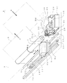
インクジェットプリンタの外観を示す図1において、インクジェットプリンタ1は、円筒形状のプラテンローラ2を有する。このプラテンローラ2は、給紙カセット又は手差し給紙部から供給された記録用紙3(記録媒体)を記録ヘッド4に対面させながら搬送するもので、左右方向に延びる回転軸(図示せず)によってフレーム5に回転可能に支承されている。記録ヘッド4は、ノズル列を構成する複数のノズルから記録用紙3に対してインクを吐出して、印刷が行われる。尚、記録用紙3は、フレーム5の後方の図示しない用紙供給口から矢符A方向に供給され、プラテンローラ2の回転により矢符B方向に送給され、図示しない用紙排出口から矢符C方向に排出されるように構成されている。
In FIG. 1 showing the appearance of the ink jet printer, the
プラテンローラ2の前方には、キャリッジ6がプラテンローラ2の軸線に沿ってD方向に移動可能に設けられている。キャリッジ6は、インクジェット式の記録ヘッド4及びこの記録ヘッド4に供給するためのインクを収容するインクカートリッジ7をそれぞれ着脱可能に搭載している。また、キャリッジ6は、プラテンローラ2の軸線と平行に設けられたキャリッジ軸8にスライド可能に嵌合する嵌合孔部6aを有し、これによって、キャリッジ6に搭載された記録ヘッド4は、プラテンローラ2の軸線に沿って、スライド移動により往復移動可能となっている。キャリッジ6を移動させるキャリッジモータ10としては例えばステップモータあるいはDCモータが使用され、ベルト11及びプーリ12,13を有するベルト機構14を介してキャリッジ6を移動させる構成とされている。
A
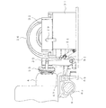
また、プラテンローラ2の右側には、記録ヘッド4の不吐出あるいは吐出不良を回復する回復装置RMが配設されている。このような回復装置RMを設けているのは、インクジェット式の記録ヘッド4であると、使用中に内部に気泡が発生したり、吐出面上にインクの液滴が付着したりする等の原因により吐出不良を起こすので、これを良好な吐出状態に回復させるためである。
Further, on the right side of the
回復装置RMとしては、記録ヘッド4のノズル面を払拭するワイパー装置21(ワイパー手段)、記録ヘッド4内の不良インクを吸引するパージ装置22(キャップ手段)、および記録ヘッド4のノズル面を覆いインク蒸発を防止する保護キャップ装置23が設けられている。
The recovery device RM covers a wiper device 21 (wiper means) for wiping the nozzle surface of the
ワイパー装置21は、進退可能に設けられ前進位置で記録ヘッド4のノズル面を払拭する板状のワイパー部材21aを備える。なお、ワイパー部材21aは、記録動作時には、後退位置とされる。
The
パージ装置22は、進退可能に設けられ前進位置で記録ヘッド4のノズル面を覆うことができる中空の吸引キャップ部材24を備える。そしてその前進位置で記録ヘッド4のノズル面を吸引キャップ部材24で覆っている状態で吸引ポンプ25により吸引キャップ部材24内に負圧を発生させ、記録ヘッド4の内部の不良インクを吸引して良好な吐出状態を回復させるように構成されている。なお、吸引キャップ部材24は、記録動作時には、後退位置とされる。
The
吸引キャップ部材24には、吸引チューブ(図示せず)を介して吸引ポンプ25に接続されている。また、この吸引ポンプ25に一端部が接続されている吐出チューブ29の他端部が、吸着材30が収容された廃インクタンク31に接続されている。従って、吸引ポンプ25によって前記吸引チューブを通じて吸引された記録ヘッド4のノズル内の不良インクは、吐出チューブ29を通じて廃インクタンク31に吐出され、そして廃インクタンク31内の吸着材30に吸着される。
The
ワイパー装置21のワイパー部材21aの進退、パージ装置22の吸引キャップ部材24の進退及び吸引ポンプ25の駆動は、ポンプカムギヤ26を回転駆動することで制御されるようになっている。即ち、具体的には図示していないが、ワイパー部材21aは後端部がポンプカムギヤ26の第1カム溝に係合するワイパー駆動部材を介して制御され、また、パージ装置22の吸引キャップ部材24は後端部が第2カム溝に係合することで、吸引ポンプ25はそれの1対のピストン(図示せず)の後端部が第3及び第4カム溝に係合することでそれぞれ制御されるようになっており、このように制御されることで一連の回復動作が行われることになる。なお、この実施の形態では、ポンプカムギヤ26の駆動(ワイパー装置21のワイパー部材21aの進退、パージ装置22の吸引キャップ部材24の進退及び吸引ポンプ25の駆動)は、紙送り装置の駆動モータ等の駆動手段により、それと係脱可能に連結する連結手段を介して駆動されるが、専用の駆動手段を設けることもできるし、ワイパー装置21のワイパー部材21aの進退、パージ装置22の吸引キャップ部材24の進退及び吸引ポンプ25の駆動を、そのようなポンプカムギヤを利用した駆動手段外の駆動手段を用いて行うこともできるのはいうまでもない。
The advance / retreat of the
また、キャリッジ6の移動方向と平行となるように廃インクタンク31にガイドロッド部材51が配設され、該ガイドロッド部材51に、保護キャップ装置23を支持する可動支持部材52がスライド移動可能かつ回転可能に支承されている。可動支持部材52は、キャリッジ6に形成された被係合部6bと係脱可能に係合する係合突部52aを有し、それによって該係合突部52aがキャリッジ6の被係合部6bに係合すると、キャリッジ6の移動に追従してスライド移動するようになっている。このスライド移動の際、可動支持部材52が、図示しない可動支持部材52の案内凸部と案内部材(図示せず)の案内傾面との係合関係で、記録ヘッド4側に回転し、記録ヘッド4のノズル面を保護キャップ装置23によって覆うようになっている。
A
また、可動支持部材52と、廃インクタンク31との間にはコイルスプリング54が介装され、可動支持部材52を、待機状態へ復帰させかつ保護キャップ装置23が記録ヘッド4から離れる方向に常時付勢する構成とされている。
In addition, a
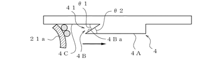
記録ヘッド4のノズル面は、図3に示すように、ノズルのインク吐出口が設けられたノズル領域面4Aに対し段差部4Bを介してノズル領域面4Aより後退した後退面4Cを有する。つまり、前記ノズル面は、ノズル領域面4Aと、段差部4Bの高さに相当する間隔だけ後退して(離れて)配置される後退面4Cとを有する。なお、このノズル領域面4Aは、ノズル領域面4Aの周囲に配置される後退面4Cに吸引キャップ部材24の開口周縁部が接触することで密閉状態で覆われる(吸引キャップ部材24の開口周縁部が接触する領域を図4に二点鎖線で示す)。
As shown in FIG. 3, the nozzle surface of the
そして、ワイパー部材21aの払拭開始側に位置する段差部4Bに、析出物質やインクミストなどの異物の溜まり部41が形成されている。
And the accumulation part 41 of foreign materials, such as a deposit substance and an ink mist, is formed in the level | step-
この異物の溜まり部41は、後退面4Cとこの後退面4Cに対し鋭角(角度θ1)をなして連続する第1の傾斜面4Baとで形成される空間部、つまりくさび形状の溝部として構成されている。後退面4Cと第1の傾斜面4Baとのなす角度θ1を鋭角としているのは、鋭角とすることで、毛細管現象により異物の溜まり部41に析出物質やインクミストなどの異物が進入しやすく、確実に捕集することができるからである。一方、鈍角とすると、通常はインクは材料への接触角が小さいため、払拭した異物が、再度濡れ広がってしまうおそれがあるからである。
The foreign matter reservoir 41 is formed as a space formed by the receding
また、第1の傾斜面4Baは、ワイパー部材21aの払拭開始側に、記録ヘッド4のノズル領域面4Aに連続しこのノズル領域面4Aに対し鋭角(角度θ2)をなす第2の傾斜面としても機能する。ここで、ノズル領域面4Aに対して角度θ2を90°より小さい鋭角とするのは、鈍角であれば、ワイパー部材21aにて、吸引キャップ部材24の接触により生ずる析出物質を確実に除去することができず、ノズルのインク吐出口に異物が到達してしまい、ノズル内に異物が侵入するおそれがあるからである。
The first inclined surface 4Ba is a second inclined surface that is continuous with the nozzle region surface 4A of the
また、ワイパー部材21aの払拭開始側に位置する段差部4Bの上縁部分G(ノズル領域面4Aの払拭開始側縁部と第1の傾斜面4Baの上縁部とが交差して形成される直線状の部分)は、ノズル面(ノズル領域面4A)に直交する方向から見て、図4に示すように、ワイパー部材21aの(相対)移動方向(払拭方向)に直交する方向に対し、例えば角度θ3(=20°)程度だけ傾斜した直線状に形成されている。払拭終了側の上縁部分Hは、ワイパー部材21aの(相対)移動方向に直交する方向に延びている。
Further, the upper edge portion G of the stepped
このように、前記上縁部分Gが傾斜することで、ワイパー部材21aの払拭動作により異物(析出物質やインクミストなど)を記録ヘッド4(ノズル面)の片側(E方向)に移動させ、集積させることができる。よって、異物の長期的な滞留を防止することができる。この場合、具体的に図示していないが、第1の傾斜面4Baは、ノズル面に直交する方向から見て、ワイパー部材21aの相対移動方向に対し傾斜して形成され、異物の溜まり部41の深さがワイパー部材21aの相対移動方向前側になるほど徐々に深くなり、異物を一層溜めやすくしている。
In this way, the upper edge portion G is inclined to move the foreign matter (deposited material, ink mist, etc.) to one side (E direction) of the recording head 4 (nozzle surface) by the wiping operation of the
キャリッジモータ10は、図示しない速度制御手段(例えばマイクロコンピュータ)に電気的に連係され、記録ヘッド4と、払拭位置にあるワイパー部材21aとの相対移動速度を制御できる構成とされている。この速度制御手段によって、ワイパー部材の払拭速度が一定あるいは可変に制御できる。この実施の形態では、例えば図5に示すように、ワイパー部材21aが段差部4B付近を通過する領域S11では、その他の領域よりも相対移動速度を低下させ、段差部4Bで異物(例えば析出物質)を掻き取り、異物の溜まり部41に溜まりやすくしている。
The carriage motor 10 is electrically linked to a speed control unit (not shown) (for example, a microcomputer), and can control the relative movement speed between the
以上の説明において、本発明の一実施の形態について説明したが、本発明はそれに限定されるものではなく、以下に述べるように種々の変更が可能である。 In the above description, an embodiment of the present invention has been described. However, the present invention is not limited thereto, and various modifications can be made as described below.
(i)前記段差部付近の断面形状としては、前述したほか、例えば図6(a)(b)に示すように、後退面4Cとの間に、異物の溜まり部が形成されるように第1の傾斜面4Ba、第2の傾斜面4Bbを有する形状であれば特に制限されず、例えば図6(c)に示すように、溝部4Cを形成することも可能である。その一方、段差部を、図6(d)に示すように後退面4Cに対して直交する面4Bcや図6(e)に示すように鈍角をなす面4Bdで構成する場合には、ワイパー部材21aから異物を掻き取る効果が低くなり、段差部を構成する面としては好ましくない。
(i) As the cross-sectional shape in the vicinity of the step portion, as described above, for example, as shown in FIGS. 6 (a) and 6 (b), a foreign matter reservoir portion is formed between the receding
(ii)前記実施の形態では、段差部の、ノズル払拭開始側の上縁部分Gは、ノズル面(ノズル領域面)に直交する方向から見て、ワイパー部材21aの相対移動方向に対し全体が同一方向に傾斜して形成されているが、図7(a)に示すように、ノズル払拭終了側の上縁部分H’を前記上縁部分Gに平行にしてもよいし、図7(b)に示すように、ノズル面に直交する方向から見て、ノズル払拭開始側の上縁部分G’を中央部がそれを挟む側部に対しワイパー部材21aの相対移動方向に対し突出するように、2つの傾斜部分G1,G2(または湾曲部分)を有する構成とすることも可能である。
(ii) In the above-described embodiment, the upper edge portion G of the stepped portion on the nozzle wiping start side as viewed from the direction perpendicular to the nozzle surface (nozzle region surface) is entirely relative to the relative movement direction of the
(iii)前記実施の形態においては、ワイパー部材21aは、それのワイパー払拭部がノズル面(ノズル領域面4A、後退面4C)に対し直交するように支持されているが、例えば図8(a)に示すように、可撓性を有する平板形状でワイパー払拭部が形成されるワイパー部材21aを、前記第1の傾斜面4Baとは反対側に傾斜した状態で支持する構成とすることも可能である。このようにすれば、異物の溜まり部内に異物を押し込めやすく、段差部4Bにおいてワイパー部材21aが引っ掛かりにくくなり、動作不良の発生を回避することができる。また、ワイパー部材21aに作用する応力も小さくなるため、隣接する別のノズルへのインクの飛散などの影響を低減する上でも有利となる。
(iii) In the above embodiment, the
一方、第1の傾斜面4Baと同方向に傾斜させておくと、図8(b)に示すように、ノズル面の掻き取り効果は高まるが、段差部4Bを有する構造の場合、その段差部4Bにワイパー部材21aが引っ掛かって動作不良が生じるおそれがある。
On the other hand, if it is made to incline in the same direction as 1st inclined surface 4Ba, as shown in FIG.8 (b), although the scraping effect of a nozzle surface will increase, in the case of the structure which has the level | step-
(iv)前記実施の形態では、記録ヘッド4のノズル領域面4Aは、ワイパー部材21aの払拭終了側に、ノズル面に対し直交する面4Dで形成しているが、例えば図9(a)に示すように、ノズル領域面4Aに鈍角をなす第3の傾斜面4Eが連続している構成とすることもできる。このようにすれば、ワイパー部材21aの払拭終了側が、図9(b)に示すようにノズル面に対し直交する面4Dで形成されていると、払拭終了時におけるワイパー部材の変形幅が大きくなり、隣接する別のノズルへのインクの飛散等の影響が生ずるが、図9(a)に示すようにノズル領域面4Aに鈍角をなす第3の傾斜面4Eとすれば、ワイパー部材21aの変形幅が小さくなるので、隣接する別のノズルにインクが飛散する等の影響を低減することができる。
(iv) In the above embodiment, the nozzle area surface 4A of the
(v)前記実施の形態においては、後退面4Cは前記ノズル領域面4Aの周囲に形成されるフラット面で、吸引キャップ部材24の開口周縁部が接触する構成されているが、後退面4Cに、吸引キャップ部材24の開口周縁部に対応する環状溝部を形成し、その間状溝部に、吸引キャップ部材24の開口周縁部が嵌り込む可能である。このようにすれば、吸引キャップ部材24のと接触部分に生じる析出物質を前記環状溝部内に溜メルコとができることになり、ワイパー部材21aの払拭動作で段差部4B側に持ち運ばれる前記析出物質を低減することができる。
(v) In the embodiment described above, the receding
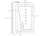
(vi)前記実施の形態では、段差部4Bの上縁部分Gが傾斜することで、ワイパー部材21aの払拭動作により異物を記録ヘッド4(ノズル面)の片側に移動させ、集積させるようにしているが、例えば図10に示すように、ノズル領域面4Aにおいて、ノズル列の両側に両側に前記上縁部分Gとほぼ平行に延びる傾斜溝61A,61Bを設け、ノズル領域面4A上でワイパー部材21aにて払拭されたインクWが傾斜溝61A,61Bに沿って、記録ヘッドの片側に移動させるようにすることも可能である。このようにすれば、段差部において掻き取られ異物の溜まり部に溜まる異物も、ノズル領域面4A上で払拭されたインクWも、同じ記録ヘッドの片側に案内して集積させることができる。
(Vi) In the above embodiment, the upper edge portion G of the stepped
(vii)ワイパー部材21aの払拭方向は、記録ヘッド4のノズル列L11が水平方向に延在する場合であっても(図11(a)参照)、ノズル列L12が垂直方向に延在する場合であってもよいが(図11(b)参照)、記録媒体全幅にわたって記録ヘッドが配置され、記録ヘッドが移動しないラインプリンタの場合には、記録ヘッドは、各色毎に設けられ、記録ヘッド間に隙間が形成されるので、前述したところの、ワイパー部材を、ノズル列方向に移動させることで、前述した実施の形態と同様の効果を得ることができる。
(vii) The wiping direction of the
(viii)前記実施の形態においては、後退位置(待機位置)と前進位置(払拭動作位置)との間を進退する(ワイパー装置の)ワイパー部材21aに対して記録ヘッド4(キャリッジ6)が移動することでノズル面(ノズル領域面4A,後退面4C)の払拭を行うようにしているが、逆に、例えば停止状態にある記録ヘッドに対しワイパー部材を、周知の駆動手段を用いて前記ノズル面に対して移動させることでノズル面の払拭を行う構成とすることもできる。例えばワイパー部材を進退させるアクチュエータを含むワイパー装置を可動台上に固定し、この可動台をガイドレールに沿って、ワイパー部材が前進位置となった状態でノズル面を払拭するように移動させる構成とすることもできる。この場合、ワイパー部材の移動方向は、レイアウト上の制約がなければ特に制限されず、水平方向であっても垂直方向であってもよい。
(viii) In the above embodiment, the recording head 4 (carriage 6) moves relative to the
(ix)前記実施の形態においては、電圧を印加すると機械的変形をする圧電素子(ピエゾ素子等)を利用してインク溝内に溜めてあるインクを吐出する圧電素子型のインクジェット記録装置に適用しているが、そのほか、インクに発熱抵抗体(硼化ジルコニウム等)の発する熱を瞬間的に与え、膜沸騰させ、その沸騰気泡の体積膨張を利用してインクを射出させるいわゆるバブルジェット(登録商標)型のインクジェット記録装置にも適用することができる。また、記録ヘッドのノズルを、水平方向に開口するものだけでなく、下向き、傾斜などの任意の方向にノズルを向けたものにも本発明を適用することができる。 (ix) In the above embodiment, the present invention is applied to a piezoelectric element type ink jet recording apparatus that uses a piezoelectric element (such as a piezo element) that mechanically deforms when a voltage is applied to discharge ink stored in an ink groove. However, in addition to this, a so-called bubble jet (registered) that instantaneously applies heat generated by a heating resistor (zirconium boride, etc.) to ink, causes film boiling, and uses the volume expansion of the boiling bubbles to eject the ink. (Trademark) type ink jet recording apparatus. Further, the present invention can be applied not only to the nozzle of the recording head that opens in the horizontal direction but also to the nozzle that faces the nozzle in an arbitrary direction such as downward or inclined.
G,G’ 上縁部分
1 インクジェット記録装置
4 記録ヘッド
4A ノズル領域面
4B 段差部
4Ba 第1の傾斜面
4Bb 第2の傾斜面
4C 後退面
21a ワイパー部材
41 異物の溜まり部
G, G ′
Claims (9)
前記ノズル面の前記後退面に当接して前記ノズル面を覆い前記ノズル面の前面の空間を密閉するキャップ部材を備えたキャップ手段と、
前記ノズル面に接離可能なワイパー部材を有し、前記記録ヘッドに対して前記ワイパー部材が相対移動することにより前記ノズル面を払拭するワイパー手段とを備えたインクジェット記録装置において、
前記ワイパー部材の払拭開始側に位置する前記段差部に、異物の溜まり部が形成されており、
前記ワイパー手段は、前記後退面の前記キャップ部材が当接した部分を払拭した後に、前記ノズル領域面を払拭することを特徴とするインクジェット記録装置。
A plurality of nozzle area surfaces provided with ink discharge ports; a retreat surface that is retreated from the nozzle area surface; and a nozzle surface that includes a step portion that connects the nozzle region surface and the retreat surface . A recording head for ejecting ink from a nozzle to a recording medium;
Cap means comprising a cap member that contacts the receding surface of the nozzle surface to cover the nozzle surface and seal a space in front of the nozzle surface ;
It has detachably wiper member to the nozzle surface, the ink jet recording apparatus having a wiper means for wiping the nozzle surface by the wiper member relative to said recording head are moved relative,
Wherein the stepped portion located in the wiping start side of the wiper member, reservoir of foreign matter is formed,
The said wiper means wipes the said nozzle area | region surface, after wiping the part which the said cap member contact | abutted of the said receding surface, The inkjet recording device characterized by the above-mentioned .
前記速度制御手段は、前記ワイパー部材が前記ノズル領域面を払拭するときよりも前記段差部を横切るときの前記相対移動速度を低下させる構成とされていることを特徴とする請求項1〜6のいずれかに記載のインクジェット記録装置。 A speed control means for controlling a relative moving speed between the recording head and the wiper member;
The speed control means is configured to reduce the relative moving speed when the wiper member crosses the stepped portion than when the wiper member wipes the nozzle region surface. An ink jet recording apparatus according to any one of the above.
前記後退面には、前記キャップ部材の周縁部が嵌り込む環状溝部が形成されていることを特徴とする請求項1〜8のいずれかに記載のインクジェット記録装置。
The receding surface is formed around the nozzle region surface and is configured to contact the opening peripheral edge of the cap member.
The inkjet recording apparatus according to claim 1, wherein an annular groove portion into which a peripheral edge portion of the cap member is fitted is formed on the receding surface.
Priority Applications (2)
| Application Number | Priority Date | Filing Date | Title |
|---|---|---|---|
| JP2005269926A JP4635794B2 (en) | 2005-09-16 | 2005-09-16 | Inkjet recording device |
| US11/532,304 US7766450B2 (en) | 2005-09-16 | 2006-09-15 | Ink jet recording apparatus |
Applications Claiming Priority (1)
| Application Number | Priority Date | Filing Date | Title |
|---|---|---|---|
| JP2005269926A JP4635794B2 (en) | 2005-09-16 | 2005-09-16 | Inkjet recording device |
Publications (2)
| Publication Number | Publication Date |
|---|---|
| JP2007076295A JP2007076295A (en) | 2007-03-29 |
| JP4635794B2 true JP4635794B2 (en) | 2011-02-23 |
Family
ID=37937038
Family Applications (1)
| Application Number | Title | Priority Date | Filing Date |
|---|---|---|---|
| JP2005269926A Expired - Fee Related JP4635794B2 (en) | 2005-09-16 | 2005-09-16 | Inkjet recording device |
Country Status (1)
| Country | Link |
|---|---|
| JP (1) | JP4635794B2 (en) |
Families Citing this family (2)
| Publication number | Priority date | Publication date | Assignee | Title |
|---|---|---|---|---|
| US8573742B2 (en) | 2008-02-14 | 2013-11-05 | Hewlett-Packard Development Company, L.P. | Wiper bumper for a fluid dispensing component |
| JP6939389B2 (en) * | 2017-10-17 | 2021-09-22 | 京セラドキュメントソリューションズ株式会社 | Head cleaning mechanism and inkjet recording device equipped with it |
Family Cites Families (5)
| Publication number | Priority date | Publication date | Assignee | Title |
|---|---|---|---|---|
| JPH0839828A (en) * | 1994-07-29 | 1996-02-13 | Canon Inc | Inkjet recording means and recording apparatus |
| US6244685B1 (en) * | 1998-05-01 | 2001-06-12 | Canon Kabushiki Kaisha | Head wiping arrangement for ink jet printer |
| JP3997046B2 (en) * | 2000-03-31 | 2007-10-24 | キヤノン株式会社 | Liquid jet recording apparatus and head cleaning method |
| JP2001301182A (en) * | 2000-04-18 | 2001-10-30 | Funai Electric Co Ltd | Ink jet printer |
| JP2002096457A (en) * | 2000-09-22 | 2002-04-02 | Hitachi Koki Co Ltd | Inkjet printer |
-
2005
- 2005-09-16 JP JP2005269926A patent/JP4635794B2/en not_active Expired - Fee Related
Also Published As
| Publication number | Publication date |
|---|---|
| JP2007076295A (en) | 2007-03-29 |
Similar Documents
| Publication | Publication Date | Title |
|---|---|---|
| JP4613978B2 (en) | Droplet discharge device | |
| US6631974B2 (en) | Ink jet recording apparatus having wiping mechanism | |
| EP2202077B1 (en) | Multicolor printhead maintenance station | |
| CN107443909B (en) | Cleaning device for liquid ejecting head and liquid ejecting apparatus | |
| JP6597650B2 (en) | Inkjet recording device | |
| US7758151B2 (en) | Wiper device and liquid ejection apparatus | |
| US8147031B2 (en) | Recording apparatus | |
| US7766450B2 (en) | Ink jet recording apparatus | |
| JP2003001833A (en) | Inkjet recording device | |
| JP5347324B2 (en) | Inkjet recording device | |
| JP4635795B2 (en) | Inkjet recording device | |
| JP4635794B2 (en) | Inkjet recording device | |
| JP4280569B2 (en) | Inkjet recording device | |
| JP2005040975A (en) | Liquid jet head wiping device and liquid jet device | |
| JP4640069B2 (en) | Inkjet recording device | |
| JP6922611B2 (en) | Inkjet recording device | |
| JP5056465B2 (en) | Liquid ejection apparatus and printing apparatus | |
| JP4258616B2 (en) | Wiping member | |
| JP4006587B2 (en) | Liquid ejector | |
| JP2004074514A (en) | Wiping member, liquid ejecting device, ink jet recording device | |
| JP2004299209A (en) | Liquid ejection characteristic maintaining device, liquid ejection device, and ink jet recording device | |
| JP6340924B2 (en) | RECOVERY SYSTEM OF PRINT HEAD, INKJET RECORDING DEVICE EQUIPPED WITH THE SAME, AND RECOVERY METHOD OF RECORD HEAD | |
| JP2013136221A (en) | Liquid discharge device | |
| JP6221946B2 (en) | RECOVERY SYSTEM OF PRINT HEAD, INKJET RECORDING DEVICE EQUIPPED WITH THE SAME, AND RECOVERY METHOD OF RECORD HEAD | |
| JP5776164B2 (en) | Maintenance unit and liquid ejecting apparatus |
Legal Events
| Date | Code | Title | Description |
|---|---|---|---|
| A621 | Written request for application examination |
Free format text: JAPANESE INTERMEDIATE CODE: A621 Effective date: 20080328 |
|
| A131 | Notification of reasons for refusal |
Free format text: JAPANESE INTERMEDIATE CODE: A131 Effective date: 20100810 |
|
| A521 | Request for written amendment filed |
Free format text: JAPANESE INTERMEDIATE CODE: A523 Effective date: 20101008 |
|
| TRDD | Decision of grant or rejection written | ||
| A01 | Written decision to grant a patent or to grant a registration (utility model) |
Free format text: JAPANESE INTERMEDIATE CODE: A01 Effective date: 20101026 |
|
| A01 | Written decision to grant a patent or to grant a registration (utility model) |
Free format text: JAPANESE INTERMEDIATE CODE: A01 |
|
| A61 | First payment of annual fees (during grant procedure) |
Free format text: JAPANESE INTERMEDIATE CODE: A61 Effective date: 20101108 |
|
| FPAY | Renewal fee payment (event date is renewal date of database) |
Free format text: PAYMENT UNTIL: 20131203 Year of fee payment: 3 |
|
| R150 | Certificate of patent or registration of utility model |
Ref document number: 4635794 Country of ref document: JP Free format text: JAPANESE INTERMEDIATE CODE: R150 Free format text: JAPANESE INTERMEDIATE CODE: R150 |
|
| LAPS | Cancellation because of no payment of annual fees |