JP4635795B2 - Inkjet recording device - Google Patents
Inkjet recording device Download PDFInfo
- Publication number
- JP4635795B2 JP4635795B2 JP2005269927A JP2005269927A JP4635795B2 JP 4635795 B2 JP4635795 B2 JP 4635795B2 JP 2005269927 A JP2005269927 A JP 2005269927A JP 2005269927 A JP2005269927 A JP 2005269927A JP 4635795 B2 JP4635795 B2 JP 4635795B2
- Authority
- JP
- Japan
- Prior art keywords
- guide
- nozzle
- wiper member
- ink
- recording apparatus
- Prior art date
- Legal status (The legal status is an assumption and is not a legal conclusion. Google has not performed a legal analysis and makes no representation as to the accuracy of the status listed.)
- Expired - Fee Related
Links
Images


Landscapes
- Ink Jet (AREA)
- Particle Formation And Scattering Control In Inkjet Printers (AREA)
Description
本発明は、インクジェット記録装置に関するものである。 The present invention relates to an ink jet recording apparatus.
従来より、記録用紙(記録媒体)を記録ヘッドに対して相対的に移動させ、前記記録ヘッドをキャリッジ上で記録用紙の幅方向に移動させながら記録用紙に対してインク滴を吐出させることで記録を行うインクジェット記録装置は知られている。 Conventionally, recording paper (recording medium) is moved relative to the recording head, and recording is performed by ejecting ink droplets onto the recording paper while moving the recording head in the width direction of the recording paper on the carriage. Inkjet recording apparatuses that perform the above are known.
そのような記録ヘッドは、ノズルからインク滴として記録用紙に吐出させて記録を行う関係上、ノズルの吐出口からのインクの蒸発に起因するインク粘度の上昇や、インクの固化、塵埃の付着、さらには気泡の混入などによりノズルの吐出口に目詰まりし、記録不良を起こすおそれがある。 Since such a recording head performs recording by ejecting ink droplets from a nozzle onto a recording sheet, ink viscosity increases due to evaporation of ink from the nozzle ejection port, ink solidification, dust adhesion, Furthermore, there is a risk of clogging of the nozzle outlet due to air bubbles and the like, resulting in recording failure.
そのために、インクジェット記録装置は、非記録時に記録ヘッドのノズル面をキャップ部材にて覆うキャップ手段と、必要に応じて記録ヘッドのノズル面をワイパー部材の払拭動作にて清掃するワイパー手段を備えているのが一般的である。 Therefore, the ink jet recording apparatus includes a cap unit that covers the nozzle surface of the recording head with a cap member during non-recording, and a wiper unit that cleans the nozzle surface of the recording head by a wiping operation of the wiper member as necessary. It is common.
そして、そのようなインクジェット記録装置においては、キャップ部材にて前記ノズル面を覆った状態でノズルのインクを吸引し、その後に、ワイパー部材により前記ノズル面を払拭して、ノズル面上のインク類(例えば紙粉、埃、増粘インクなど)を除去する操作が行われる。 In such an ink jet recording apparatus, the nozzle ink is sucked in a state where the nozzle surface is covered with a cap member, and then the nozzle surface is wiped with a wiper member, so that inks on the nozzle surface are collected. An operation for removing (for example, paper dust, dust, thickened ink, etc.) is performed.
そのようなインクジェット記録装置において、ノズルプレート上にクレータ部をワイピング上流側に設け、このクレータ部に、ノズルプレートやワイパー部材に付着した前記インク類を一旦掻き落とし、クリーニング時にキャップにて覆い、吸引によりノズルプレート上から除去するものが知られている(例えば、特許文献1参照)。
そのような記録装置では、ノズルプレート上にクレータ部を設け、そのクレータ部の段差を利用してインク類をワイパー部材から拭き落とすようにしているだけであり、インク類を運ぶ方向はワイパー部材の払拭動作の方向であるので、クレータ部での拭き落としが十分でないと、ノズルの吐出口に目詰まりし、記録不良を起こすおそれが残されている。 In such a recording apparatus, a crater portion is provided on the nozzle plate, and only the ink is wiped off from the wiper member using the step of the crater portion. Since it is the direction of the wiping operation, if the crater portion is not sufficiently wiped off, there is a possibility that the nozzle outlet will be clogged and cause a recording failure.
この発明は、ワイパー部材の払拭動作によりインク類をノズル領域外に向けて案内することで、ノズルの吐出口の目詰まりを防止したインクジェット記録装置を提供することを目的とする。 SUMMARY OF THE INVENTION An object of the present invention is to provide an ink jet recording apparatus that prevents clogging of nozzle discharge ports by guiding inks to the outside of a nozzle region by a wiping operation of a wiper member.
請求項1の発明は、複数のノズルから記録媒体に対してインクを吐出する記録ヘッドと、前記記録ヘッドのノズル面をキャップ部材にて覆うキャップ手段と、前記記録ヘッドに対しワイパー部材が相対移動することにより前記記録ヘッドのノズル面を前記ワイパー部材にて払拭するワイパー手段とを備えるインクジェット記録装置において、前記記録ヘッドのノズル面には、前記ノズルが設けられているノズル領域の周囲に、前記ワイパー部材にて払拭したインク類を、前記ワイパー部材の払拭動作により前記ノズル領域外に向けて案内する案内部が設けられ、前記ノズル面は、前記ノズル領域を形成した第1の部分と、前記第1の部分の外側にて前記キャップ部材と接触する第2の部分とを有し、前記第1の部分は,前記第2の部分より高くなるような段差状に形成され、前記案内部は、前記第1の部分に、前記外側になるほど前記ワイパー部材の相対移動方向の前側に位置するように設けられ、前記案内部の外側端部である下流端が前記第1の部分において開放され、前記ワイパー部材は、少なくともノズルから前記案内部の前記下流端までを払拭するように動作することを特徴とする。 According to a first aspect of the present invention, there is provided a recording head that ejects ink from a plurality of nozzles onto a recording medium, a cap unit that covers a nozzle surface of the recording head with a cap member, and a wiper member that moves relative to the recording head. And a wiper means for wiping the nozzle surface of the recording head with the wiper member, wherein the nozzle surface of the recording head has a nozzle region around the nozzle region where the nozzle is provided. an ink such that the wiping by the wiper member, the guide portion for guiding towards outside the nozzle area is provided et al is a wiping operation of the wiper member, the nozzle surface has a first portion which forms the nozzle region, A second portion that contacts the cap member outside the first portion, wherein the first portion is higher than the second portion. The guide portion is provided in the first portion so as to be located on the front side in the relative movement direction of the wiper member at the first portion, and at the outer end portion of the guide portion. A downstream end is opened in the first portion, and the wiper member operates to wipe at least from the nozzle to the downstream end of the guide portion .
このようにすれば、記録ヘッドのノズル面には、ノズルが設けられているノズル領域の周囲に、前記ワイパー部材にて払拭したインク類を、前記ワイパー部材の払拭動作により前記ノズル領域外に向けて案内する案内部が設けられているので、ワイパー部材の払拭動作により前記ノズル領域外に向けてインク類が案内される。このように、ワイパー部材の払拭動作により、案内部を通じてノズル領域外に向けてインク類が案内されるので、ノズル領域におけるノズルの吐出口に目詰まりを防止して、長期にわたり安定したインク噴射特性を維持することができる。 In this way, the ink wiped by the wiper member is directed to the outside of the nozzle area on the nozzle surface of the recording head by the wiping operation of the wiper member around the nozzle area where the nozzle is provided. Therefore, the ink is guided out of the nozzle region by the wiping operation of the wiper member. As described above, the wiper member wiping operation guides the inks to the outside of the nozzle region through the guide portion. Therefore, the nozzle ejection port in the nozzle region is prevented from being clogged, and stable ink ejection characteristics over a long period of time. Can be maintained.
請求項2の発明は、請求項1のインクジェット記録装置において、前記案内部が、外側になるほど、前記ワイパー部材の相対移動方向の前側に位置するように傾斜している複数の案内領域を備え、これら案内領域は一旦その領域内に進入したインク類をその領域内に留める保持機能を有していることを特徴とする。 According to a second aspect of the present invention, in the ink jet recording apparatus of the first aspect, the guide unit includes a plurality of guide regions that are inclined so as to be positioned on the front side in the relative movement direction of the wiper member as the guide portion is located on the outer side. These guide areas have a holding function for retaining the inks once entering the area in the area.
このようにすれば、案内領域は一旦その領域内に進入したインクをその領域内に留める保持機能を有しているので、ワイパー部材の払拭動作により前記案内領域内にインク類が侵入すると、そのインク類は案内領域外、つまりノズル領域域内に出ることがない。よって、そのインク類は案内領域に留められ、ワイパー部材の払拭動作により、前記案内領域を通じて前記ノズル領域外に向けて案内される。 In this way, since the guide area has a holding function for retaining the ink that has once entered the area, if the ink enters the guide area by the wiping operation of the wiper member, The inks do not go out of the guide area, that is, into the nozzle area. Therefore, the inks are retained in the guide area, and are guided outside the nozzle area through the guide area by the wiping operation of the wiper member.
請求項3の発明は、請求項2のインクジェット記録装置において、前記複数の案内領域が、複数の案内溝からなることを特徴とする。 According to a third aspect of the present invention, in the ink jet recording apparatus according to the second aspect, the plurality of guide areas include a plurality of guide grooves.
このようにすれば、案内部が案内溝として構成されるので、インク類が案内溝内に留められ、ワイパー部材の払拭動作により案内溝を通じてノズル領域外にスムーズに案内される。 In this case, since the guide portion is configured as a guide groove, the inks are retained in the guide groove and smoothly guided outside the nozzle region through the guide groove by the wiping operation of the wiper member.
請求項4の発明は、請求項3のインクジェット記録装置において、前記複数の案内溝が、それぞれ外側に向かって溝深さが徐々に深くなっていることを特徴とする。 According to a fourth aspect of the present invention, in the ink jet recording apparatus according to the third aspect, the groove depth of each of the plurality of guide grooves gradually increases toward the outside.
このようにすれば、各案内溝が、外側に向かって溝深さが徐々に深くなっているので、外側に向かって案内溝内のインク類が流れやすくなり、案内溝による(インク類の)案内効果が向上する。 In this way, since the groove depth of each guide groove gradually increases toward the outside, the ink in the guide groove easily flows toward the outside, and the guide groove (of inks) The guidance effect is improved.
請求項5の発明は、請求項2〜4のいずれかのインクジェット記録装置において、前記複数の案内領域が、前記ノズル面よりも濡れやすくなるように前記ノズル面に対し撥インク処理が施されていることを特徴とする。 According to a fifth aspect of the present invention, in the inkjet recording apparatus according to any one of the second to fourth aspects, the nozzle surface is subjected to an ink repellent treatment so that the plurality of guide regions are more easily wetted than the nozzle surface. It is characterized by being.
このようにすれば、インク類が案内領域内に進入しやすくなるとともに、インク類は案内領域に留められやすくなる。よって、ワイパー部材の払拭動作により、案内領域内のインク類はその案内領域に沿って、ノズル領域外に流れるように案内される。よって、ワイパー部材の払拭動作によるインク類の案内効果が向上する。 In this way, the inks can easily enter the guide area, and the inks can be easily retained in the guide area. Therefore, by the wiping operation of the wiper member, the inks in the guide area are guided to flow out of the nozzle area along the guide area. Therefore, the ink guiding effect by the wiping operation of the wiper member is improved.
請求項6の発明は、請求項2〜5のいずれかのインクジェット記録装置において、前記案内領域の外側部分付近に、前記ワイパー部材にて払拭したインク類をトラップ可能なトラップ部が配設されていることを特徴とする。 According to a sixth aspect of the present invention, in the ink jet recording apparatus according to any one of the second to fifth aspects, a trap portion capable of trapping inks wiped by the wiper member is disposed near the outer portion of the guide region. It is characterized by being.
このようにすれば、案内領域の外側部分付近にトラップ部が配設されているので、インク類が案内領域を通じて、その案内領域の外側部分に案内されると、トラップ部にてトラップされ、インク類がノズル領域に戻るのが抑制される。 In this way, since the trap portion is disposed in the vicinity of the outer portion of the guide region, when ink is guided to the outer portion of the guide region through the guide region, the trap portion traps the ink. Class is prevented from returning to the nozzle area.
以上のように、本発明は、記録ヘッドのノズル面において、ノズルが設けられているノズル領域の周囲に、ワイパー部材にて払拭したインク類を、前記ワイパー部材の払拭動作により前記ノズル領域外に向けて案内する案内部を設けているので、ワイパー部材の払拭動作の際に、前記案内部を利用してインク類を前記ノズル領域外に向けて案内することができる。よって、インク類が、ノズルの吐出口に目詰まりし、記録不良を起こす原因となるのを回避することができ、長期にわたり安定したインク噴射特性を維持することが可能となる。 As described above, according to the present invention, the ink wiped by the wiper member around the nozzle area where the nozzle is provided on the nozzle surface of the recording head is moved out of the nozzle area by the wiping operation of the wiper member. Since the guide portion is provided to guide the ink, the ink can be guided outside the nozzle region by using the guide portion during the wiping operation of the wiper member. Therefore, it can be avoided that inks are clogged in the nozzle outlet and cause a recording defect, and stable ink ejection characteristics can be maintained over a long period of time.
以下、本発明の実施の形態を図面に沿って説明する。 Hereinafter, embodiments of the present invention will be described with reference to the drawings.
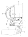
インクジェットプリンタの外観を示す図1において、インクジェットプリンタ1は、円筒形状のプラテンローラ2を有する。このプラテンローラ2は、給紙カセット又は手差し給紙部から供給された記録用紙3(記録媒体)を記録ヘッド4に対面させながら搬送するもので、左右方向に延びる回転軸(図示せず)によってフレーム5に回転可能に支承されている。記録ヘッド4は、ノズル列を構成する複数のノズル4a(図3参照)から記録用紙3に対してインクを吐出して、印刷が行われる。尚、記録用紙3は、フレーム5の後方の図示しない用紙供給口から矢符A方向に供給され、プラテンローラ2の回転により矢符B方向に送給され、図示しない用紙排出口から矢符C方向に排出されるように構成されている。
In FIG. 1 showing the appearance of the ink jet printer, the
プラテンローラ2の前方には、キャリッジ6がプラテンローラ2の軸線に沿ってD方向に移動可能に設けられている。キャリッジ6は、インクジェット式の記録ヘッド4及びこの記録ヘッド4に供給するためのインクを収容するインクカートリッジ7をそれぞれ着脱可能に搭載している。また、キャリッジ6は、プラテンローラ2の軸線と平行に設けられたキャリッジ軸8にスライド可能に嵌合する嵌合孔部6aを有し、これによって、キャリッジ6に搭載された記録ヘッド4は、プラテンローラ2の軸線に沿って、スライド移動により往復移動可能となっている。キャリッジ6を移動させるキャリッジモータ10としては例えばステップモータあるいはDCモータが使用され、ベルト11及びプーリ12,13を有するベルト機構14を介してキャリッジ6を移動させる構成とされている。
A
また、プラテンローラ2の右側には、記録ヘッド4の不吐出あるいは吐出不良を回復する回復装置RMが配設されている。このような回復装置RMを設けているのは、インクジェット式の記録ヘッド4であると、使用中に内部に気泡が発生したり、吐出面上にインクの液滴が付着したりする等の原因により吐出不良を起こすので、これを良好な吐出状態に回復させるためである。
Further, on the right side of the
回復装置RMとしては、記録ヘッド4のノズル面を払拭するワイパー装置21(ワイパー手段)、記録ヘッド4内の不良インクを吸引するパージ装置22(キャップ手段)、および記録ヘッド4のノズル面を覆いインク蒸発を防止する保護キャップ装置23が設けられている。
The recovery device RM covers a wiper device 21 (wiper means) for wiping the nozzle surface of the
ワイパー装置21は、進退可能に設けられ前進位置で記録ヘッド4のノズル面を払拭する板状のワイパー部材21aを備える。なお、ワイパー部材21aは、記録動作時には、後退位置とされる。
The
パージ装置22は、進退可能に設けられ前進位置で記録ヘッド4のノズル面を覆うことができる中空の吸引キャップ部材24を備える。そしてその前進位置で記録ヘッド4のノズル面を吸引キャップ部材24で覆っている状態で吸引ポンプ25により吸引キャップ部材24内に負圧を発生させ、記録ヘッド4の内部の不良インクを吸引して良好な吐出状態を回復させるように構成されている。なお、吸引キャップ部材24は、記録動作時には、後退位置とされる。
The purge device 22 includes a hollow
吸引キャップ部材24には、吸引チューブ(図示せず)を介して吸引ポンプ25に接続されている。また、この吸引ポンプ25に一端部が接続されている吐出チューブ29の他端部が、吸着材30が収容された廃インクタンク31に接続されている。従って、吸引ポンプ25によって前記吸引チューブを通じて吸引された記録ヘッド4のノズル内の不良インクは、吐出チューブ29を通じて廃インクタンク31に吐出され、そして廃インクタンク31内の吸着材30に吸着される。
The
ワイパー装置21のワイパー部材21aの進退、パージ装置22の吸引キャップ部材24の進退及び吸引ポンプ25の駆動は、ポンプカムギヤ26を回転駆動することで制御されるようになっている。即ち、具体的には図示していないが、ワイパー部材21aは後端部がポンプカムギヤ26の第1カム溝に係合するワイパー駆動部材を介して制御され、また、パージ装置22の吸引キャップ部材24は後端部が第2カム溝に係合することで、吸引ポンプ25はそれの1対のピストン(図示せず)の後端部が第3及び第4カム溝に係合することでそれぞれ制御されるようになっており、このように制御されることで一連の回復動作が行われることになる。なお、この実施の形態では、ポンプカムギヤ26の駆動(ワイパー装置21のワイパー部材21aの進退、パージ装置22の吸引キャップ部材24の進退及び吸引ポンプ25の駆動)は、紙送り装置の駆動モータ等の駆動手段により、それと係脱可能に連結する連結手段を介して駆動されるが、専用の駆動手段を設けることもできるし、ワイパー装置21のワイパー部材21aの進退、パージ装置22の吸引キャップ部材24の進退及び吸引ポンプ25の駆動を、そのようなポンプカムギヤを利用した機構以外の機構を用いて行うこともできるのはいうまでもない。
The advance / retreat of the wiper member 21a of the
また、キャリッジ6の移動方向と平行となるように廃インクタンク31にガイドロッド部材51が配設され、該ガイドロッド部材51に、保護キャップ装置23を支持する可動支持部材52がスライド移動可能かつ回転可能に支承されている。可動支持部材52は、キャリッジ6に形成された被係合部6bと係脱可能に係合する係合突部52aを有し、それによって該係合突部52aがキャリッジ6の被係合部6bに係合すると、キャリッジ6の移動に追従してスライド移動するようになっている。このスライド移動の際、可動支持部材52が、図示しない(可動支持部材52の)案内凸部と案内部材(図示せず)の案内傾面との係合関係で、記録ヘッド4側に回転し、記録ヘッド4のノズル面を保護キャップ装置23によって覆うようになっている。
A guide rod member 51 is disposed in the waste ink tank 31 so as to be parallel to the moving direction of the
また、可動支持部材52と、廃インクタンク31との間にはコイルスプリング54が介装され、可動支持部材52を、待機状態へ復帰させ、かつ保護キャップ装置23が記録ヘッド4から離れる方向に常時付勢する構成とされている。
In addition, a
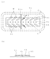
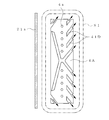
また、記録ヘッド4のノズル面4Aにおいて、図3(a)に示すように、ノズル4a(ノズル列)が設けられているノズル領域の周囲に、ワイパー部材21aにて払拭したインク類(例えば紙粉、埃、増粘インクなど)を、ワイパー部材21aの払拭動作により前記ノズル領域外に向けて案内する案内領域として複数の案内溝41が設けられている。複数の案内溝41は、それぞれ外側(ノズル面4Aの縁部)に向かって、ワイパー部材21aの相対移動方向(払拭方向A)の前側に向かって傾斜して形成されている。その案内溝41の溝深さは、図3(b)に示すように外側になるほど徐々に深くなっている。なお、図3(a)において鎖線S1で示す部分はキャップ部材24の開口周縁部とノズル面との接触部分である。
In addition, on the nozzle surface 4A of the
上記のように構成すれば、ワイパー部材21の払拭動作時にそのワイパー部材21の払拭動作により、ワイパー部材21aにて払拭されたインク類Wが、まず、案内溝41内に持ち込まれ、その持ち込まれたインク類Wが、案内溝41を通じて前記ノズル領域外に向けて、すなわちB方向に案内される。よって、インク類Wはワイパー部材21aの払拭動作によりノズル領域およびその近傍に存在しなくなり、それらから離れた、ノズル領域外の案内溝41の下流端付近に貯留される。
If comprised as mentioned above, the ink W wiped by the wiper member 21a by the wiping operation of the
このように、ワイパー部材21aの払拭動作により、インク類Wが案内溝41を通じてノズル領域外に向けて案内されるので、ワイパー部材21aによる払拭動作および案内溝41によるノズル領域外への案内機能の相乗効果によりワイパー部材21aによる払拭効果が高められ、長期にわたり安定したインク噴射特性を維持することが可能となる。
Thus, since the inks W are guided to the outside of the nozzle region through the
以上の説明において、本発明の一実施の形態について説明したが、本発明はそれに限定されるものではなく、以下に述べるように種々の変更が可能である。 In the above description, an embodiment of the present invention has been described. However, the present invention is not limited thereto, and various modifications can be made as described below.
(i)前記実施の形態においては、案内領域として案内溝41を単に形成しているだけであるが、案内溝による案内効果を高めるために、案内溝内部の方がノズル面(案内溝が形成されている部分を除くノズル面)よりもインクによって濡れやすくなるように、前記ノズル面側に周知の撥インク処理を施すことも可能である。
(i) In the above embodiment, the
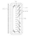
また、必ずしも案内領域を、案内溝として形成する必要はなく、例えば図4に示すように、外側になるほど、前記ワイパー部材の相対移動方向の前側に位置するように傾斜している複数の案内領域S11(前記案内溝41に対応する)を配置し、この案内領域S11以外のノズル面4Aを構成する領域S12の部分に対し撥インク処理を施すことで、これら案内領域S11は一旦その領域S11内に進入したインクをその領域S11内に留める保持機能を有する構成とすることで、案内溝41を設けた場合と同様な効果を得ることも可能である。ここで、案内領域S11と領域S12とは、同一面(ノズル面)上に配置される。
Further, it is not always necessary to form the guide region as a guide groove. For example, as shown in FIG. 4, a plurality of guide regions that are inclined so as to be located on the front side in the relative movement direction of the wiper member as shown in FIG. S11 (corresponding to the guide groove 41) is arranged, and the ink repellent process is performed on the portion of the region S12 constituting the nozzle surface 4A other than the guide region S11, so that these guide regions S11 are once in the region S11. It is possible to obtain the same effect as the case where the
(ii)前記案内領域の外側部分付近に、例えば前記キャップ部材と前記ノズル面との接触位置の外側に、前記ワイパー部材21aにて払拭したインク類をトラップ可能なトラップ部(例えば吸湿性を有するフェルト材など)が配設されている構成とすることも可能である。 (Ii) A trap portion (for example, having a hygroscopic property) that can trap ink wiped by the wiper member 21a near the outer portion of the guide region, for example, outside the contact position between the cap member and the nozzle surface. It is also possible to adopt a configuration in which a felt material or the like is provided.
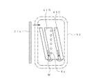
(iii)ワイパー部材によってノズル列の延在する方向に対して直交する方向に払拭動作される記録ヘッドの場合には、例えば図5に示すように、ノズル列の払拭終了側に、ノズル4aの配列方向に延在する複数の案内溝41A(または案内領域)を放射状に形成したり、図6に示すように、ノズル列の払拭開始側と払拭終了側とに、ノズル列に対して一定角度傾斜した案内溝41B,41Cを設けることで、同様に適用することが可能となる。 (Iii) In the case of a recording head that is wiped by a wiper member in a direction orthogonal to the direction in which the nozzle row extends, as shown in FIG. 5, for example, on the wiping end side of the nozzle row, A plurality of guide grooves 41A (or guide areas) extending in the arrangement direction are formed radially, or, as shown in FIG. 6, a fixed angle with respect to the nozzle row on the wiping start side and the wiping end side of the nozzle row By providing the inclined guide grooves 41B and 41C, it can be similarly applied.
(iv)また、図5の形態の変形例として、図7に示すように、ノズル4aの列を2つに分割して、ノズル列の払拭終了側に形成した案内溝41Dを2つのノズル列の間からノズル列の払拭開始側まで延存させる構成とすることもできる。これによれば、ノズル面4の払拭開始側に存在するインクもノズル列を避けて払拭終了側に案内することができる。
(iv) As a modification of the embodiment of FIG. 5, as shown in FIG. 7, the nozzle 4 a row is divided into two, and guide
(v)前記実施の形態においては、後退位置(待機位置)と前進位置(払拭動作位置)との間を進退する(ワイパー装置の)ワイパー部材21aに対して記録ヘッド4(キャリッジ6)が移動することでノズル面の払拭を行うようにしているが、逆に、例えば停止状態にある記録ヘッドに対しワイパー部材を、周知の駆動手段を用いて前記ノズル面に対して移動させることでノズル面の払拭を行う構成とすることもできる。例えばワイパー部材を進退させるアクチュエータを含むワイパー装置を可動台上に固定し、この可動台をガイドレールに沿って、ワイパー部材が前進位置となった状態でノズル面を払拭するように移動させる構成とすることもできる。この場合、ワイパー部材の移動方向は、レイアウト上の制約がなければ特に制限されず、水平方向であっても垂直方向であってもよい。 (v) In the above embodiment, the recording head 4 (carriage 6) moves relative to the wiper member 21a (of the wiper device) that moves back and forth between the retracted position (standby position) and the advanced position (wiping operation position). The nozzle surface is wiped off by moving the wiper member with respect to the nozzle surface, for example, with respect to the recording head in a stopped state by using a known driving means. It can also be set as the structure which wipes. For example, a wiper device including an actuator for moving the wiper member forward and backward is fixed on a movable base, and the movable base is moved along the guide rail so as to wipe the nozzle surface in a state where the wiper member is in the forward position. You can also In this case, the movement direction of the wiper member is not particularly limited unless there is a restriction on the layout, and may be a horizontal direction or a vertical direction.
(vi)記録媒体全幅にわたって記録ヘッドが配置され、記録ヘッドが移動しないラインプリンタの場合にも同様に適用することができる。つまり、記録ヘッドは、各色毎に設けられ、記録ヘッド間に隙間が形成されるので、前述したところの、払拭したインク類をノズル列から離れる方向に案内する部分を備えるワイパー部材を、ノズル列方向に移動させることで同様に効果を期待することができる。 (vi) The present invention can be similarly applied to a line printer in which the recording head is arranged over the entire width of the recording medium and the recording head does not move. In other words, since the recording head is provided for each color and a gap is formed between the recording heads, the wiper member having a portion for guiding the wiped ink away from the nozzle array as described above is provided in the nozzle array. The effect can be similarly expected by moving in the direction.
(vii)前記実施の形態においては、電圧を印加すると機械的変形をする圧電素子(ピエゾ素子等)を利用してインク溝内に溜めてあるインクを噴射する圧電素子型のインクジェット記録装置に適用しているが、そのほか、インクに発熱抵抗体(硼化ジルコニウム等)の発する熱を瞬間的に与え、膜沸騰させ、その沸騰気泡の体積膨張を利用してインクを射出させるいわゆるバブルジェット(登録商標)型のインクジェット記録装置にも適用することができる。また、記録ヘッドのノズルを、水平方向に開口するものだけでなく、下向き、傾斜などの任意の方向にノズルを向けたものにも本発明を適用することができる。 (vii) In the above embodiment, the present invention is applied to a piezoelectric element type ink jet recording apparatus that ejects ink stored in an ink groove using a piezoelectric element (such as a piezo element) that mechanically deforms when a voltage is applied. However, in addition to this, a so-called bubble jet (registered) that instantaneously applies heat generated by a heating resistor (zirconium boride, etc.) to ink, causes film boiling, and uses the volume expansion of the boiling bubbles to eject the ink. (Trademark) type ink jet recording apparatus. Further, the present invention can be applied not only to the nozzle of the recording head that opens in the horizontal direction but also to the nozzle that faces the nozzle in an arbitrary direction such as downward or inclined.
S11 案内領域
1 インクジェット記録装置
4 記録ヘッド
4A ノズル領域部分
4a ノズル
41,41A〜41C 案内溝(案内部)
Claims (6)
前記記録ヘッドのノズル面には、前記ノズルが設けられているノズル領域の周囲に、前記ワイパー部材にて払拭したインク類を、前記ワイパー部材の払拭動作により前記ノズル領域外に向けて案内する案内部が設けられ、
前記ノズル面は、前記ノズル領域を形成した第1の部分と、前記第1の部分の外側にて前記キャップ部材と接触する第2の部分とを有し、
前記第1の部分は、前記第2の部分より高くなるような段差状に形成され、
前記案内部は、前記第1の部分に、前記外側になるほど前記ワイパー部材の相対移動方向の前側に位置するように設けられ、前記案内部の外側端部である下流端が前記第1の部分において開放され、
前記ワイパー部材は、少なくともノズルから前記案内部の前記下流端までを払拭するように動作することを特徴とするインクジェット記録装置。 A recording head that discharges ink from a plurality of nozzles to a recording medium; a cap unit that covers a nozzle surface of the recording head with a cap member; and a wiper member that moves relative to the recording head to move the recording head. In an inkjet recording apparatus comprising a wiper means for wiping the nozzle surface with the wiper member,
On the nozzle surface of the recording head, a guide for guiding the inks wiped by the wiper member around the nozzle area where the nozzles are provided, toward the outside of the nozzle area by the wiping operation of the wiper member. part is provided, et al. are,
The nozzle surface has a first portion that forms the nozzle region, and a second portion that contacts the cap member outside the first portion,
The first part is formed in a stepped shape so as to be higher than the second part,
The guide portion is provided in the first portion so as to be located closer to the front side in the relative movement direction of the wiper member toward the outer side, and a downstream end that is an outer end portion of the guide portion is the first portion. Released at
The inkjet recording apparatus , wherein the wiper member operates to wipe at least from the nozzle to the downstream end of the guide portion .
6. The ink jet recording apparatus according to claim 2, wherein a trap portion capable of trapping inks wiped by the wiper member is disposed near an outer portion of the guide region.
Priority Applications (2)
| Application Number | Priority Date | Filing Date | Title |
|---|---|---|---|
| JP2005269927A JP4635795B2 (en) | 2005-09-16 | 2005-09-16 | Inkjet recording device |
| US11/532,304 US7766450B2 (en) | 2005-09-16 | 2006-09-15 | Ink jet recording apparatus |
Applications Claiming Priority (1)
| Application Number | Priority Date | Filing Date | Title |
|---|---|---|---|
| JP2005269927A JP4635795B2 (en) | 2005-09-16 | 2005-09-16 | Inkjet recording device |
Publications (2)
| Publication Number | Publication Date |
|---|---|
| JP2007076296A JP2007076296A (en) | 2007-03-29 |
| JP4635795B2 true JP4635795B2 (en) | 2011-02-23 |
Family
ID=37937039
Family Applications (1)
| Application Number | Title | Priority Date | Filing Date |
|---|---|---|---|
| JP2005269927A Expired - Fee Related JP4635795B2 (en) | 2005-09-16 | 2005-09-16 | Inkjet recording device |
Country Status (1)
| Country | Link |
|---|---|
| JP (1) | JP4635795B2 (en) |
Families Citing this family (9)
| Publication number | Priority date | Publication date | Assignee | Title |
|---|---|---|---|---|
| JP5038110B2 (en) * | 2007-11-27 | 2012-10-03 | キヤノン株式会社 | Inkjet recording head and inkjet recording apparatus |
| JP2010208224A (en) * | 2009-03-11 | 2010-09-24 | Sii Printek Inc | Liquid jetting head, liquid jetting recording apparatus and method of filling liquid into liquid jetting head |
| JP5516088B2 (en) * | 2010-06-01 | 2014-06-11 | コニカミノルタ株式会社 | Inkjet head and inkjet recording apparatus |
| JP2016022654A (en) * | 2014-07-18 | 2016-02-08 | エスアイアイ・プリンテック株式会社 | Ink jet head and liquid jet recording device |
| CN105128544A (en) * | 2015-09-01 | 2015-12-09 | 宁波荣大昌办公设备有限公司 | Paper conveying structure under ink jetting area |
| JP6575501B2 (en) * | 2016-12-22 | 2019-09-18 | 京セラドキュメントソリューションズ株式会社 | Inkjet recording device |
| JP6589893B2 (en) * | 2017-01-18 | 2019-10-16 | 京セラドキュメントソリューションズ株式会社 | Head cleaning mechanism and ink jet recording apparatus having the same |
| JP6961978B2 (en) * | 2017-03-30 | 2021-11-05 | ブラザー工業株式会社 | Droplet ejection head |
| CN108773186B (en) * | 2018-08-14 | 2023-10-27 | 北京捷润科技有限公司 | Spray head protection device and protection method |
Family Cites Families (4)
| Publication number | Priority date | Publication date | Assignee | Title |
|---|---|---|---|---|
| JPH0232857A (en) * | 1988-07-22 | 1990-02-02 | Matsushita Electric Ind Co Ltd | inkjet recording device |
| JPH0252752A (en) * | 1988-08-17 | 1990-02-22 | Canon Inc | inkjet recording device |
| JPH08230185A (en) * | 1995-03-01 | 1996-09-10 | Brother Ind Ltd | Inkjet device |
| JP3428254B2 (en) * | 1995-10-25 | 2003-07-22 | セイコーエプソン株式会社 | Ink jet recording device |
-
2005
- 2005-09-16 JP JP2005269927A patent/JP4635795B2/en not_active Expired - Fee Related
Also Published As
| Publication number | Publication date |
|---|---|
| JP2007076296A (en) | 2007-03-29 |
Similar Documents
| Publication | Publication Date | Title |
|---|---|---|
| EP0913263B1 (en) | Hide-away wiper cleaner for inkjet printheads | |
| JP4613978B2 (en) | Droplet discharge device | |
| JP3171280B2 (en) | Inkjet printer | |
| JPH07205434A (en) | Fixed wiper blade assembly | |
| CN107443909B (en) | Cleaning device for liquid ejecting head and liquid ejecting apparatus | |
| CN101092081A (en) | Image forming apparatus and method of driving the same | |
| JP6597650B2 (en) | Inkjet recording device | |
| JP4635795B2 (en) | Inkjet recording device | |
| US20140035996A1 (en) | Print head servicing units and methods | |
| JP2004042537A (en) | Inkjet recorder and recovery mechanism part thereof | |
| US7766450B2 (en) | Ink jet recording apparatus | |
| JP5170158B2 (en) | Liquid ejecting apparatus and liquid wiping apparatus | |
| JP2011121295A (en) | Fluid jet apparatus | |
| JP2009269327A (en) | Inkjet recorder | |
| JP4640069B2 (en) | Inkjet recording device | |
| JP2016210051A (en) | Cleaning mechanism of ink head | |
| JP4635794B2 (en) | Inkjet recording device | |
| JP2007130807A (en) | Inkjet recording device | |
| JP2005342991A (en) | Liquid ejecting apparatus and liquid absorbing apparatus for liquid ejecting head | |
| JP6683951B2 (en) | Device for ejecting liquid | |
| JP3922222B2 (en) | Liquid ejection apparatus and control method thereof | |
| JP6379948B2 (en) | Liquid ejection device | |
| JP4738191B2 (en) | Inkjet printer | |
| JPH08142345A (en) | Inkjet device | |
| JP2007144838A (en) | Liquid ejector |
Legal Events
| Date | Code | Title | Description |
|---|---|---|---|
| A621 | Written request for application examination |
Free format text: JAPANESE INTERMEDIATE CODE: A621 Effective date: 20080328 |
|
| A131 | Notification of reasons for refusal |
Free format text: JAPANESE INTERMEDIATE CODE: A131 Effective date: 20100810 |
|
| A521 | Request for written amendment filed |
Free format text: JAPANESE INTERMEDIATE CODE: A523 Effective date: 20101007 |
|
| TRDD | Decision of grant or rejection written | ||
| A01 | Written decision to grant a patent or to grant a registration (utility model) |
Free format text: JAPANESE INTERMEDIATE CODE: A01 Effective date: 20101026 |
|
| A01 | Written decision to grant a patent or to grant a registration (utility model) |
Free format text: JAPANESE INTERMEDIATE CODE: A01 |
|
| A61 | First payment of annual fees (during grant procedure) |
Free format text: JAPANESE INTERMEDIATE CODE: A61 Effective date: 20101108 |
|
| FPAY | Renewal fee payment (event date is renewal date of database) |
Free format text: PAYMENT UNTIL: 20131203 Year of fee payment: 3 |
|
| R150 | Certificate of patent or registration of utility model |
Ref document number: 4635795 Country of ref document: JP Free format text: JAPANESE INTERMEDIATE CODE: R150 Free format text: JAPANESE INTERMEDIATE CODE: R150 |
|
| LAPS | Cancellation because of no payment of annual fees |